Geometrical Optics. Have you ever entered an unfamiliar room in which one wall was covered with a
|
|
|
- Erika Henderson
- 5 years ago
- Views:
Transcription

? You may know that it s all done with mirrors.")
1 Return to Table of Contents HAPTER24 C. Geometrical Optics A mirror now used in the Hubble space telescope Have you ever entered an unfamiliar room in which one wall was covered with a mirror and thought at first that the room extended beyond the mirrored wall that the image you saw in the mirror was real? Or have you seen, at an amusement park or novelty store, an object appear to be floating in air, when in fact there is really nothing there (Fig. 24 2)? You may know that it s all done with mirrors. But have you wondered just how mirrors can be used to create such convincing illusions? In this chapter we will answer such questions, developing concepts and equations to describe the behavior of mirrors as an application of the law of reflection, presented in the last chapter. We shall see, for example, that a plane mirror can create a perfect optical image. There is no way not to be fooled by a plane mirror covering a wall if the mirror is very clean and very flat. In this chapter we shall also apply the law of refraction to gain an understanding of lenses and their uses. For example, we shall see why focusing a camera requires changing the distance between the camera lens and the film. In the following chapter we will apply our knowledge of mirrors and lenses, developed in this chapter, to explain optical systems: magnifiers, microscopes, telescopes, eyeglasses, and even the human eye itself. Fig. 24 Which is the mirror image? How do you know? 662

.")

2 24 Plane Mirrors 663 Fig Illusions created with mirrors. Part of what appears to be real in each of these pictures is actually just an image formed by light. Can you tell which parts? None of the coins you see are really where they appear to be, and where you see a light bulb, no real light bulb is present. The meter stick passes through the mirror image of the bulb. For explanations, see Example 4 and Problem Plane Mirrors Fig A point source of light P and its image P, in a plane mirror. Each light ray from P that strikes the mirror satisfies the law of reflection (angle of incidence angle of reflection). Extending the reflected rays back behind the mirror (dashed lines), we see that the reflected rays are diverging from P, the image point. Fig indicates how a plane mirror forms an image of a point source of light P. (The point source could be a tiny light bulb, for example.) Rays of light from P are reflected from the mirror, each ray satisfying the law of reflection. If the reflected rays are extended back behind the mirror, these extensions all intersect at a point P, as indicated in the figure. The reflected rays diverge from this point. The reflected light appears to an observer to be coming from P because the eye interprets light rays as having traveled in a straight line. In other words, the eye sees an image at P. A plane mirror is a perfect optical instrument if its surface is a perfect plane. All rays coming from P are imaged precisely at P. The drawing of reflected rays in Fig indicates an image point directly behind the mirror and at the same distance from the mirror as the source point.


3 664 CHAPTER 24 Geometrical Optics A geometric proof of this result is given in Fig Notice that P need not be directly in front of part of the mirror. A ray incident on the mirror at any angle will be reflected along a line from P, where P is a point directly behind the plane of the mirror, the same distance d from the plane as the point P. The image at point P is called a virtual image point. In general, images are referred to as either real or virtual. A real image point is defined as a point at which converging light rays intersect. A virtual image point is defined as a point from which rays of light appear to be diverging, though the rays do not actually intersect at the image point. Although a plane mirror produces a virtual image, we shall see that curved mirrors and lenses sometimes produce real images. Fig The blue dashed line through object point P is perpendicular to the plane of a mirror. The extension of any reflected light ray behind the mirror intersects this line at a point P. Because the angle of reflection equals the angle of incidence, P is the same distance d from the mirror plane as the object point. This conclusion is valid for any light ray at any angle of incidence. Thus all reflected rays appear to be coming from P. Fig Observer O sees the image at point P, but observer O does not see the image. For an observer to see an image, the mirror must cross the line between the observer s eye and the image point (Fig. 24 5). When a mirror forms an image of an extended object, each point on the object serves as a point source of light, from which light rays are emitted. The image formed by the mirror consists of image points corresponding to the object points (Fig. 24 6). Image and object points are an equal distance from the mirror (P and P, Q and Q, and so forth). Reflected light appears to be coming from the image points. Notice that the image has the same size as the object. (a) (b) Fig The image of an extended object in a plane mirror.
. These images correspond to reflections from either M or M 2.")
 Thus the point P serves as an object for the second mirror.")

4 24 2 Spherical Mirrors 665 EXAMPLE Multiple Images In Perpendicular Mirrors Locate all the images of a point source P located near two perpendicular plane mirrors M and M 2 (Fig. 24 7). SOLUTION Each mirror will produce an image of the object: image points P in M and P 2 in M 2 (Fig. 24 8a). These images correspond to reflections from either M or M 2. It is also possible to have rays reflected by both mirrors. As indicated in Fig. 24 8b, if light strikes M 2 after being reflected from M, the ray incident on M 2 appears to be coming from P. (Remember all light reflected from M appears to be coming from P.) Thus the point P serves as an object for the second mirror. Applying our rule for locating a mirror image, we find that the image of P in mirror M 2 is formed at P 3 (Fig. 24 8c). To an observer, the ray shown in this figure appears to be coming from P 3. In following this simple method of locating images, the rays we have constructed automatically satisfy the law of reflection at each mirror. In this example we have found the image produced by one optical element (mirror M ) and then used that as an object for a second optical element (mirror M 2 ) to find an image (P 3 ). We shall use this general procedure in solving many optical problems involving combinations of mirrors or lenses. Fig (a) (b) Fig Three virtual images of a candle flame are seen in two perpendicular mirrors. (c) Fig Spherical Mirrors Many optical devices use curved mirrors, either concave or convex (Fig. 24 0). A concave mirror is used, for example, as part of a reflecting telescope. Convex mirrors are often seen in stores, where they are used to give a wide-angle view. The reflecting surface of a concave or convex spherical mirror is part of a spherical surface. Concave Spherical Mirrors First we shall describe qualitatively how a concave spherical mirror forms images and then obtain a formula for locating images. Fig. 24 shows image formation by a concave mirror in a series of ray diagrams. A point object is infinitely far away in the first drawing and is brought closer in each successive drawing. (a) (b) Fig (a) A concave mirror. (b) A convex mirror.
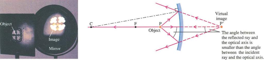
5 666 CHAPTER 24 Geometrical Optics (a) Parallel rays from a distant point source are reflected by a concave mirror and converge to form a real image. The distant object point is on the optical axis, a line perpendicular to the center of the reflecting surface. The image point F is called the focal point. The distance f from the mirror to the focal point is called the focal length. The center of curvature C is the center of the spherical reflecting surface. (b) A point object at P a distance s from the mirror produces a real image at P a distance s from the mirror. In this drawing the incident and reflected rays at the top of the mirror make a smaller angle than in the preceding drawing. The object is closer to the mirror and the image is farther away than in (a). (c) The object P is at the same point occupied by the image in (b). Therefore the incident rays are just the reverse of the reflected rays in (b). The law of reflection then predicts that the reflected rays here will be the reverse of the former incident rays. The paths of the rays in both figures are the same, but the directions of the rays are opposite. This means that object and image points are interchanged. This result is an example of a general principle, the principle of optical reversibility: One may always interchange an object and an image, reversing the directions of all rays. This principle applies to both reflection and refraction and follows from the fact that the laws of reflection and refraction do not involve the direction of light rays. (d) The object is placed at the focal point F. Applying the principle of optical reversibility to (a), where F was an image point, we find that the image here is at infinity, the location of the object point in (a). (e) When the object is placed inside the focal point, the incident and reflected rays form larger angles, and the reflected rays no longer intersect. Instead the reflected rays diverge from a point P behind the mirror, forming a virtual image as in the case of a plane mirror.

")
 (e)")
6 24 2 Spherical Mirrors 667 (a) (b) (c) (d) (e)

7 668 CHAPTER 24 Geometrical Optics Fig Light rays diverging from object point P are reflected from a concave mirror and converge at image point P. The image distance s depends on the object distance s and on the mirror s radius of curvature. Next we shall derive an equation relating object and image distances. Fig shows a light ray originating at object point P, reflecting from a concave mirror, and crossing the optical axis at P, the image point. We shall see that all rays originating at P cross the axis at the same point P if the angles,, and are all fairly small, say, less than 0. We shall apply the geometric theorem that states that an exterior angle of a triangle equals the sum of the two opposite interior angles (Fig. 24 3). Applying this first to triangle PAC and then to triangle PAP, we find Fig Exterior angle 4 equals the sum of the two opposite interior angles, and 2. 2 Eliminating between these two equations gives 2 (24 ) From inspection of Fig. 24 2, we can relate angles,, and to the respective linear distances s, R, and s, using the radian definition of an angle (the arc length of a circular segment divided by its radius). We assume that the angles,, and are all small angles (less than about 0), and so the circular arcs corresponding to these angles all have approximately the same length d. Thus d d d R s s Substitution into Eq. 24 yields or d d 2d s s R 2 s R (24 2) s This result is independent of the particular angle of the incident ray; that is, it applies to all incident rays that make small angles with the optical axis. All such rays, called paraxial rays, converge to the image point P located a distance s from the vertex. For a distant object point P, we can set s equal to. The image then is at the focal point (s f ), and the equation above gives 2 f R
8 24 2 Spherical Mirrors 669 or R f (24 3) 2 Substituting this expression for f into Eq gives: s f (spherical mirror; paraxial rays) (24 4) s This mirror equation may be used to locate an image point, given the position of the object point. If we interchange s and s in the mirror equation, the equation is unchanged. This im - plies the principle of optical reversibility, since interchanging s and s in this equation corresponds to physically interchanging object and image. For example, we have seen that s, sf satisfies the mirror equation. If we interchange these values, we obtain s f, s, again satisfying the mirror equation. The two meanings of the focal point, indicated in Fig. 24 a and 24 d, correspond to these two choices of s and s. EXAMPLE 2 Image of a Distant Point in a Concave Mirror A concave spherical mirror has a radius of curvature of 20.0 cm. A small source of light is directly in front of the mirror, 0 m away. Find the position of the real image produced by the mirror. SOLUTION (Eq. 24 3). We first apply the equation for the focal length f R cm 0.00 m Then we apply the mirror equation, setting the object distance s 0 m, and solve for the image distance s. s s s f s 9.90 m f 0.00 m 0 m s0.0 m 0. cm The image is located on the optical axis, 0. cm in front of the mirror, very close to the focal point. Whenever the object distance is much greater than the focal length, the image will be very close to the focal point. If either incident or reflected rays make relatively large angles with the optical axis, these rays will not all converge at exactly the same image point. This means that the image produced will be somewhat fuzzy or blurred. This is illustrated in Fig. 24 4a for a distant point source on the optical axis. This effect, known as spherical aberration, is not present in parabolic mirrors (Fig. 24 4b), which are commonly used in astronomical telescopes. (a) (b) Fig (a) Rays from a distant point source on the optical axis are incident on a spherical mirror. Only paraxial rays converge at the focal point. (b) For a parabolic mir - ror all rays from a distant point source on the optical axis converge at the focal point.


9 670 CHAPTER 24 Geometrical Optics Virtual Images The mirror equation may also be applied when a virtual image is produced, but in this case we must treat the image distance s as a negative quantity, as shown in Fig Here we introduce the first of several sign conventions that are essential to successful problem solving in geometrical optics: Image distance s 0 Reflected rays converge toward a real image in front of the mirror. s 0 Reflected rays diverge from a virtual image behind the mirror. (24 5) (24 6) With this sign convention for s and others for s and R, we shall be able to apply the mirror equation to any problem involving spherical mirrors. Fig Derivation of an equation to locate the virtual image formed by a con - cave mirror when an object is inside the mirror s focal point. If we take the image distance s to be negative, we obtain the same equation used for a real image. Virtual Objects When incident light rays converge toward a point P behind a mirror, as in Fig. 24 6, we refer to the point of convergence as a virtual object point. Virtual objects occur when a mirror interrupts converging light rays before a real image can be formed. These con - verging rays must be produced by some other converging mirror or lens (Fig. 24 7). Once again the mirror equation is applicable (Problem 2 outlines a proof), but here we must treat the object distance s as a negative quantity. The sign convention for the object distance therefore is: Object distance s 0 Incident rays diverge from a real object in front of the mirror. (24 7) s 0 Incident rays converge toward a virtual object behind the mirror. (24 8) Fig A virtual object point P. Light rays converging toward P are interrupted by a mirror before reaching that point. (a) (b) Fig (a) A lens forms a real image. (b) A concave mirror is placed in front of the image, which then serves as a virtual object for the mirror. The mirror image of this object is formed in front of the mirror.
 if we interpret the radius of curvature R as a signed quantity and use the following sign convention: Radius of curvature R 0 concave mirror R 0 convex")

10 24 2 Spherical Mirrors 67 Convex Spherical Mirrors Both the mirror equation and the focal length equation ( f R/2), which we have derived for concave mirrors, turn out to be applicable to convex mirrors as well (Problem 3 outlines a proof) if we interpret the radius of curvature R as a signed quantity and use the following sign convention: Radius of curvature R 0 concave mirror R 0 convex mirror (24 9) (24 0) The focal length then is positive for concave mirrors and negative for convex mirrors. R f 0 for a concave mirror (24 ) 2 R f 0 for a convex mirror (24 2) 2 Fig shows how images are formed by a convex mirror. Notice that in all cases the convex mirror tends to diverge rays; that is, the reflected rays either diverge more than the incident rays (Fig. 24 8a and 24 8b), or they converge less (Fig. 24 8c). A convex mirror is a diverging mirror. (a) (b) (c) Fig Image formation by a convex mirror.

11 672 CHAPTER 24 Geometrical Optics Linear Magnification A spherical mirror can be used to magnify an object, that is, to produce an image larger than the object (Fig. 24 9). We shall obtain an equation that will allow us to determine the size of a mirror image from its location. Fig When a mirror image is farther from the mirror than the object, it is also larger than the object. Each point on an extended object has a corresponding image point. Fig shows an object arrow with points P and Q at the ends; rays from P are imaged at P and rays from Q are imaged at Q. Two rays are shown coming from Q. One of these passes through the center of curvature, and since this ray is perpendicular to the mirror s surface, it is reflected back on itself. The second incident ray strikes the mirror at an angle above the optical axis and is therefore reflected at the same angle below the axis. The intersection of these two rays locates the image point Q. Fig Linear magnification by a concave mirror: the image PQ is larger than the object PQ.
12 24 2 Spherical Mirrors 673 We can obtain a relationship between object and image heights by inspecting triangles PQV and PQV, from which we see that tan y s y s The minus sign in this equation is due to the fact that the image is inverted, and therefore image point Q has a negative y coordinate. We define the linear magnification m to be the ratio y/y of the coordinates of image point Q and object point Q. Solving the equation above for y/y, we find y s m (24 3) y s This equation allows us to calculate both the size and the orientation of the image relative to the object. When s s, that is, when the image distance is greater than the object distance, m, meaning that the image is larger than the object, as in Fig When the image is nearer the mirror than the object (s s), m, meaning that the image is smaller than the object. The sign of m indicates the relative orientation of image and object. If m is positive, this means that the y coordinates of image and object have the same sign the image is upright. If m is negative, the y coordinates have opposite signs the image is inverted, as in Fig Fortunately Eq may be applied to all situations for which the mirror equation is applicable: concave or convex mirrors, real or virtual objects and images. EXAMPLE 3 A Woman s Image in a Convex Mirror A woman of height.7 m (56) stands directly in front of a convex spherical mirror 2.0 m away. The mirror has a radius of curvature R 50 cm. Find the location and size of the woman s image. SOLUTION (Eq. 24 3). First we apply the equation for the focal length R 50 cm f 25 cm 2 2 The convex mirror has a negative focal length. Next we apply the mirror equation (Eq. 24 4), and solve for the image distance s. s 200 cm s s f 25 cm s22 cm The plane of the woman s image is 22 cm behind the vertex, or about 3 cm in front of the focal point. Applying the formula for linear magnification (Eq. 24 3), we find s 22 cm m 0. s 200 cm or Solving for y, we obtain y y 0. y0.y (0.)(.7 m) 0.9 m 9 cm The woman s upright image is just 9 cm high. The mirror pro - duces a miniaturized image of distant objects, as does the mirror in Fig. 24 0b. You can also see this effect if you look at your reflection in the convex side of a shiny spoon.
13 674 CHAPTER 24 Geometrical Optics Graphical Method The position and size of an image may be found without any calculation, using a graphical method. Several special rays are drawn from the tip of the object arrow. The rays, called principal rays, make use of properties of the focal point and center of curvature so that the paths of these rays can be drawn. The rays locate the image point at the tip of the image arrow. The graphical method is illustrated in Fig. 24 2, where it is applied to several different situations. There are three kinds of principal rays, which are used in all cases. The incident principal rays are: A ray parallel to the optical axis, as though coming from an object at ; 2 A ray in a direction as though coming from an object at the focal point (or, in the case of a convex mirror, directed toward an object at the focal point); 3 A ray along a line through the center of curvature. It is easy to draw the complete paths of these rays. For example, for a concave mirror: the first ray is reflected in a direction such that it passes through the focal point; the second ray is reflected parallel to the optical axis; the third ray is reflected back through the center of curvature. Any two of the reflected rays are sufficient to locate the image. The third ray serves as a check. Once the image is found, any other ray from the object may be drawn. The graphical method is a helpful complement to the use of equations in problem solving. However, in applying this method, you must be careful to draw to scale the various distances along the optical axis: the object distance, the radius of curvature, and the focal length. Concave mirrors Real object, real image (a) Real object, virtual image Convex mirrors Real object, virtual image (b) Virtual object, virtual image Fig The graphical method applied to (a) concave mirrors; (b) convex mirrors.

14 24 2 Spherical Mirrors 675 EXAMPLE 4 The Phantom Light Bulb This example shows how the image of a light bulb in Fig is created. Let the base of an inverted light bulb be placed at the center of curvature of a concave spherical mirror of radius 80 cm. Find the location, size, and orientation of the image. SOLUTION We apply the mirror equation, setting the object distance equal to the radius of curvature and using the fact that f R/2. s s f s R s f R/2 R sr 80 cm Thus the image distance is the same as the object distance. The image lies in the same plane as the object. Next we calculate the magnification. Fig s R m s R The image is the same size as the object, but it is inverted (Fig ). The object bulb is directly beneath the image in the photograph in Fig Application of the graphical method, shown in Fig , helps in understanding how the image is formed. EXAMPLE 5 Image of a Virtual Object A real image of height 2 cm is formed by a concave mirror. Then a second mirror of radius 20 cm is placed 0 cm in front of the image (Fig a), so that the converging rays strike the second mirror before the image is formed. Find the image formed by the second mirror. SOLUTION The image formed by the first mirror serves as a virtual object for the second mirror, with an object distance s 0 cm. We apply the mirror equation, using the focal length of 20 cm/2 0 cm. s 0 cm s s f 0 cm (a) 2 s 0 cm 5cm s5 cm A real image is formed 5 cm in front of the mirror. To find the size and orientation of the image, we apply the equation for linear magnification. m y y s s s 5 cm yy (2 cm) cm s 0 cm Thus the tip of the image arrow is cm below the optical axis. Application of the graphical method is shown in Fig b. Notice that the vertical and horizontal scales are different. (b) Fig


 Convex converging surface (b) Concave converging surface (a) Converging lens (b) Converging lens (c) Diverging lens (d) Diverging lens Fig. 24 26 Spherical lenses.")


15 676 CHAPTER 24 Geometrical Optics Fig Lens grinding Lenses One of the oldest and most important applications of optical principles is the design of lenses for use in various instruments eyeglasses, cameras, microscopes, and so forth. Most lenses are made by forming spherical surfaces on both sides of a circular glass disk. Spherical surfaces are most common because they are the easiest to make (Fig ). Refraction at a spherical surface is also relatively easy to describe mathematically. Thus we begin our study of lenses with a description of refraction at various spherical surfaces. Fig shows parallel rays of light incident on spherical surfaces, separating two media with different refractive indices n and n (for example, air and glass). As seen in the figure, transmitted rays either converge toward the optical axis, forming a real image, or diverge from the axis, forming a virtual image. Which they do is dependent both on the kind of surface (concave or convex) and whether the second medium has a larger or smaller index than the first. (a) Convex converging surface (b) Concave converging surface (a) Converging lens (b) Converging lens (c) Diverging lens (d) Diverging lens Fig Spherical lenses. (c) Concave diverging surface (d) Convex diverging surface Fig Determination of a surface as converging or diverging follows from the rule that rays transmitted into a higher-index medium bend toward the normal, and rays transmitted into a lower-index medium bend away from the normal. One must be careful in the designation of surfaces as concave or convex because there are two sides from which to view the surface, and a surface that is convex from one side is concave from the other. Here we adopt the convention of always viewing the surface from the side of the incident light. This convention is used in labeling surfaces in Fig The amount of bending at a surface depends on the magnitude of the radius of curvature. The more curved a surface (that is, the shorter the radius of curvature), the greater is the refraction. Normally a lens is made of glass, a relatively high-index medium, and is surrounded by air, a lower-index medium. There are several general shapes, illustrated in Fig In each case, two surfaces from Fig are combined to produce a lens. For example, Fig a shows a lens formed when the surfaces in Figs a and 24 25b are combined. All the lenses in Fig illustrate the following simple but general rule: converging lenses are thicker in the middle than at the edge, and diverging lenses are thinner in the middle than at the edge.
.")
16 24 3 Lenses 677 Refraction at a Spherical Surface First we shall show how to locate the image formed by refraction at a single spherical surface, and then we shall describe image formation by a thin lens with two such surfaces. Paraxial rays from an object point P are imaged by a spherical refracting surface at an image point P (Fig ). Object and image distances, s and s, are related by the following equation (for which a derivation is provided at the end of this section): n s n nn (24 4) s R where n and n are the refractive indices of the two media and R is the radius of curvature of the surface. We may use Eq to locate images in much the same way we used the mirror equation. If we adopt the following sign conventions for s, s, and R, this one equation may be applied to both concave and convex surfaces and to both real and virtual objects and images: Object distance s 0 Incident rays diverge from a real object in front of the surface (incident side). (24 5) s 0 Incident rays converge toward a virtual object behind the surface (transmitted side). (24 6) Image distance s 0 Transmitted rays converge toward a real image behind the surface (transmitted side). s 0 Transmitted rays diverge from a virtual image in front of the surface (incident side). (24 7) (24 8) Radius of curvature R 0 concave surface R 0 convex surface (24 9) (24 20) Notice that the sign conventions for s and s are the same as for mirrors, except that images are formed by transmitted light rather than by reflected light. Real images are formed by transmitted light behind the refracting surface, whereas for mirrors real images are formed by reflected light in front of the mirrored surface. Virtual images are formed in front of a refracting surface, in contrast to mirrors, for which virtual images are behind the surface. The sign convention for the radius of curvature is the opposite of that for mirrors. Fig Refraction at a spherical surface produces an image at P of an object at P.
 rays at a flat surface if we let R so that the right side of this equation equals zero.")
.")

17 678 CHAPTER 24 Geometrical Optics A flat surface can be thought of as the surface of an infinite sphere. Thus Eq may be applied to refraction of paraxial (small-angle) rays at a flat surface if we let R so that the right side of this equation equals zero. EXAMPLE 6 The Apparent Depth of a Fish Find the apparent depth of a small fish.00 m below the surface of a lake when viewed from directly overhead. SOLUTION Light rays diverging from a point on the fish are bent away from the normal as they pass from water to air (Fig a). Since the fish is viewed from directly above, the light rays entering the observer s eye make a small angle with the normal; that is, they are paraxial. Thus we can apply Eq to find the image distance s. n s n s nn R Light travels a distance s.00 m from water of refractive index.33 to air of index.00. The flat refracting surface corresponds to R. Thus m s (a).33 m s s 0.75 m 75 cm The water forms a virtual image of the fish 75 cm below the sur - face. The fish, like all underwater objects, appears to be closer to the surface than it really is. If we view a submerged object from the side, rather than from directly above the object, the effect is much more dramatic (Fig b). The object can be more than twice as deep as it appears. See Problem 5, Chapter 23. (Eq does not apply unless the object is viewed from directly above because only then is the assumption of paraxial rays satisfied.) To a Scuba diver looking through a diving mask, underwater objects also appear closer than they are (Fig ). The mask traps a layer of air in front of the diver s eye. The thin flat layer of plastic at the front of the mask has little effect on the incident light (like the windowpane in Example 4, Chapter 23). Thus the light effectively passes from water to air, and everything the diver sees appears closer than it really is, just as for an observer looking down into a body of water. (b) Fig Fig
18 24 3 Lenses 679 Thin Lenses We shall now derive an equation describing image formation by a thin lens with spherical surfaces. We do this by twice applying the equation for refraction at a spherical surface (Eq. 24 4). At the first surface, light travels from air with index to glass with index n. Thus we have n n s (24 2) s At the second surface, light travels from glass to air, and we obtain n n s2 (24 22) s2 The object for the second surface is the image produced by the first. Since the lens is assumed to be thin, the image produced by the first surface is approximately the same distance from either surface. Thus s 2 s If the first image is real, the second object is virtual (Fig ), and if the first image is virtual, the second object is real. Therefore in all cases s and s 2 have opposite signs. s 2 s R Substituting this result into Eq and adding Eq. 24 2, we obtain s2 (n ) R R2 s Here s is the distance from the object to the first surface and s 2 is the distance from the second surface to the final image. We now drop the subscripts on object and image distances, and, since the lens is assumed to be thin, we measure these distances from the center of the lens. R2 s (n ) R R2 (24 23) s For distant objects, s and /s 0. We identify the corresponding image point as a focal point ; the focal length f is the value of the image distance, the distance from the lens to the focal point. s s f Inserting these values into Eq , we obtain an expression for the focal length, known as the lensmaker s equation : Fig The image formed by a lens s first surface serves as an object for its second surface. R R2 f (n ) (thin lens in air) (24 24) Substitution of this expression into Eq gives an equation relating object and image distances, which is identical to the mirror equation. Here we shall call it the thin lens equation: s f (thin lens; paraxial rays) (24 25) s

19 680 CHAPTER 24 Geometrical Optics (a) The thin lens equation is applied to lenses in the same way that it is applied to mirrors, except, of course, that lens images are formed by transmitted light, rather than by reflected light. For a lens in a medium other than air, one can show (Problem 40) that the derivation of the lensmaker s equation is modified in such a way that the lens index n is replaced by the ratio of the lens index to the index of the surrounding medium; that is, n n/n o, where n o is the index of the outer medium. n n R R2 f o (thin lens; outer medium n o ) (24 26) (b) (c) Positive Lenses Fig shows effects predicted by the thin lens equation for a positive-focal-length lens, with a point object at various positions on the optical axis. A distant object produces an image at the focal point (s, s f ) in Fig. 24 3a. Fig. 24 3d shows another interpretation of the focal point. In this figure rays diverge from a point F located a distance f to the left of the lens. The values s f, s also satisfy the thin lens equation, meaning that an object at the focal point produces an image at. Notice that in all cases the lens tends to converge rays; that is, the transmitted rays either converge, or they diverge less than the incident rays (as in Fig. 24 3e). See Fig. 24 for comparison with a converging mirror. (d) When an object is just outside the focal point of a positive lens, the dis - tance from lens to image is much greater than the focal length. (e) Fig Image formation by a positive lens. A point object on the optical axis is at a great distance in (a) and is closer to the lens in each successive illustration. As the object comes closer, the image moves away. The principle of optical reversibility is illustrated by the interchange of objects and images in (a) and (d) and again in (b) and (c).
. A negative lens forms a virtual image of any real object.")
20 24 3 Lenses 68 Negative Lenses A negative-focal-length lens is a diverging lens, as illustrated in Fig Fig a shows parallel incident rays from a distant object producing a virtual image at the focal point (s, s f 0). A negative lens forms a virtual image of any real object. A real image may be formed, however, if the object is virtual. In particular, a virtual object at the focal point results in an image at (Fig c). See Fig for comparison with a diverging mirror. Optical Power The lensmaker s equation (Eq ) indicates how the focal length of a lens is determined by the index of the glass and the curvature of the two surfaces. The lensmaker s equation predicts that flatter surfaces with larger radii of curvature will have longer focal lengths. Fig shows three lenses with progressively shorter focal lengths. The focal lengths decrease as the surfaces become more curved (smaller magnitude R s). For very short focal lengths, the lens must be small. The optical power P o of a lens is defined as the inverse of its focal length. P o (24 27) f The standard unit of optical power is the diopter, abbreviated d, defined to be an inverse meter. d m For example, a 2 d lens has a focal length of m, and a 3 2 d lens has a focal length of 3 m. Optical power is a measure of the ability of a lens to refract light; it measures the bending power of the lens. A short-focal-length, positive lens converges incident parallel rays in a short distance. Hence it is a high-power lens. High-power lenses are small (Fig c). Similarly, a short-focal-length, negative lens is a small, high power lens. Fig Image formation by a negative lens. (a) (b) (c) Fig Three lenses with progressively shorter focal lengths. A very short focal length, or high optical power, requires very small radii of curvature, which means a high power lens must be small.
 Sketch the lens. (b) Find the optical power and focal length of the lens. (c) The lens is used as a burn ing glass.")
21 682 CHAPTER 24 Geometrical Optics EXAMPLE 7 Focusing the Sun s Rays With a Lens The first surface of a certain lens is convex, and the second surface is concave. Each surface has a radius of curvature of magnitude 0 cm. (a) Sketch the lens. (b) Find the optical power and focal length of the lens. (c) The lens is used as a burn ing glass. The sun s rays are focused by the lens on a dry leaf, causing it to ignite. How far is the leaf from the lens? (d) Now suppose the leaf is viewed through the lens, with the leaf placed.0 cm from the lens. Where does the leaf appear to be? SOLUTION (a) Fig a shows a sketch of the lens, with the surfaces labeled in reference to their curvature as seen from the left side, assumed to be the side of the incident light. (b) To find the focal length, we apply the lensmaker s equation (Eq ): (n ) R R2 Following the sign convention for spherical refracting surfaces, we have convex: R 0 cm concave: R 2 0 cm Using these values for the radii and n.5 for the index, the lensmaker s equation gives f (.5.0) f 0 cm 0 cm 0 cm Thus f 0 cm 0.0 m and P 0 d f 0.0 m Notice that f R. One can show that this simple relationship holds for any symmetric lens made of glass with an index of.5 (Problem 37). (c) To concentrate solar energy on the leaf, we should place it at the focal point of the lens, so that parallel rays from a point on the sun converge to a point on the leaf (Fig b). (d) We apply the thin lens equation (Eq ), and solve for the image distance, using an object distance of.0 cm. s s f 9 s s f 0 cm.0 cm 0 cm 0 s cm. cm 9 This means the virtual image of the leaf is very close to the object, as shown in Fig c. The cone of rays seen by the observer passes through the center section of the thin lens, which is nearly flat and which therefore produces almost no bending of rays (see Example 4, Chapter 23). In general, as an object is brought very close to a lens, so that s is much smaller than f, the virtual image formed by the lens is at nearly the same position as the object. (a) (b) (c) Fig
22 24 3 Lenses 683 EXAMPLE 8 Finding the Focal Length of a Lens A certain thin lens has surfaces with radii R 20 cm and R 2 0 cm. Sketch the lens. Find the focal length and the image distance for an object distance of 20 cm. SOLUTION Since both radii are positive, both surfaces are convex. The first surface has the larger radius, meaning that it is flatter (Fig ). Applying the lensmaker s equation, we find f (n ) R R2 (.5.0) f 40 cm Next we apply the thin lens equation to find s. s s f 20 cm 0 cm 40 cm Fig This image is virtual and is located 3 cm in front of the lens. The effect of the lens is to diverge the incident rays, so that the object appears closer to the lens than it really is (Fig ). s f s 40 cm s3 cm 20 cm Linear Magnification Each point on an extended object will have a corresponding image point produced by a lens. As shown in Fig , the linear magnification of such images is described by the same equation used to describe spherical mirrors: y s m (24 28) y s The derivation in Fig is for a real image of a real object, but the result is valid for all cases described by the thin-lens equation. Fig Derivation of the magnification equation for a real image of a real object. The ray striking the center of the lens passes straight through. This section of the lens is approximately like a flat, thin sheet of glass and, as seen in Example 4, Chapter 23, will not change the direction of the incident ray.
 If you photograph someone 0.0 m away from the camera, what must the distance between the lens and the film be?")
23 684 CHAPTER 24 Geometrical Optics EXAMPLE 9 Photographing Someone at a Distance and Close-up A certain 35 mm camera uses a lens with a focal length of 50.0 mm (Fig ). Each frame of photographic film is 24 mm wide and 35 mm long. (a) If you photograph someone 0.0 m away from the camera, what must the distance between the lens and the film be? Treat the lens as a thin lens. (b) If the subject is 2.0 m tall, how high is his image on the film? (c) How much will the distance between the film and the lens need to be changed so that you can shoot a close-up of the subject at a dis - tance of 40 cm from the lens? (d) What are the maximum dimensions of the subject that will be seen in the close-up photo? Fig SOLUTION (a) We apply the thin lens equation (Eq ) to find the image distance. s f s m 0.0 cm s m 50.3 mm The image is formed 50.3 mm behind the lens, and this should be the location of the photographic film for a clear image to be formed on it. Notice that this distance is nearly equal to the focal length. Whenever the object distance is much greater than the fo - cal length, as it is here, the image lies approximately in the focal plane. All object distances from 0 m to infinity have correspond ing image distances, which are all very nearly equal to 50 mm. (b) We apply the magnification equation (Eq ) to find the height of the image on the film (Fig ). y s m y s ys (2.0 m)( y 2 m) s 0 m m 0 mm (c) We again apply the thin lens equation. s f s m m s m 57 mm Thus the distance between the film and the lens must be in - creased by 7 mm so that you can focus on the closer object. (d) We apply the magnification equations, solving for the object height y: y s m y s ys y s We can apply this equation for both horizontal and vertical directions. Corresponding to the film width (y24 mm), we have an object distance (24 mm)(40 cm) y 7 cm 57 mm and corresponding to the film length (y35 mm), we have an object distance (35 mm)(40 cm) y 25 cm 57 mm The close-up photo covers a 7 cm by 25 cm field of view, a head shot. Fig
24 Graphical Method A graphical method may be used to obtain the position and size of an image, without calculation. The method is essentially the same as that used for spherical mirrors. The following principal rays are drawn from the tip of the object arrow: A ray parallel to the optical axis, as though coming from an object at ; 2 A ray in a direction as though coming from an object at the focal point (or, in the case of a negative lens, directed toward an object at the focal point); 3 A ray through the center of the lens. The only difference from the principal rays of mirrors is the third principal ray. The third ray for mirrors passes through the center of curvature and therefore is reflected back along the same path. The third principal ray for a lens passes straight through the center of the lens, without being bent. The graphical method is illustrated in Fig Lenses 685 Fig The graphical method applied to positive and negative lenses.
25 686 CHAPTER 24 Geometrical Optics EXAMPLE 0 Finding the Final Image Produced by Two Lenses (a) An object cm high is placed 5 cm in front of a converging (b) The real image formed by the first lens serves as a virtual lens with a focal length of 0 cm. Find the position, size, and object for the second lens (Fig b). Notice that the three orientation of the image, both by calculation and by using the principal rays are all directed toward the virtual object. The final graphical method. (b) A second lens of focal length 7.5 cm is image is 5 cm to the right of the second lens and is three times placed 25 cm to the right of the first lens. Find the final image. the size of the previous image, or 6 cm high. Again the results are verified by calculation: SOLUTION (a) The graphical solution is shown in Fig a. (Notice that horizontal and vertical distances are not drawn to the same scale.) The image is 30 cm to the right of the s f s lens, is inverted, and is twice the size of the object. These results are verified when you apply the thin lens equation and the mag cm 5 cm 5 cm nification equation: s5 cm s f s 0 cm 5 cm s30 cm s 30 cm m 2 s 5 cm 30 cm s 5 cm m 3 s 5 cm (a) (b) Fig
 the refractive index of the lens glass is a constant n for light of any wavelength, so that dispersion is negligible; (4) the objects are relatively small and close to the optical axis,")
26 Aberrations Various approximations, both explicit and implicit, have gone into our analysis of spherical thin lenses: () the lens thickness is negligible compared to other distances; (2) the rays are paraxial; (3) the refractive index of the lens glass is a constant n for light of any wavelength, so that dispersion is negligible; (4) the objects are relatively small and close to the optical axis, so that the image is undistorted and lies approximately in a plane. These approximations are often not well satisfied in actual applications of a single thin lens. Variations from our ideal description, resulting from the failure of various approximations, are called aberrations; some of these are illustrated in Figs to Fortunately, in any particular application it is possible to design lens combinations to correct for the aberrations that are of most significance. For example, two glass lenses with different dispersion curves can be combined to eliminate chromatic aberration, as shown in Fig Lenses 687 Fig Chromatic aberration, illustrated in (a) and (b), is caused by dispersion of light in glass, a prismlike effect. The amount of dispersion depends on the kind of glass used for the lens. The negative lens in (b) uses a glass with greater dispersion (a larger variation in n) than the positive lens in (a), but because the shape of the negative lens results in less refraction (a longer focal length), the angular spread of the spectrum for the two lenses is the same. Thus combining the lenses, as shown in (c), results in a positive-focal-length lens, which displays no dispersion. Such a combination is called an achromatic doublet. Illustrations (a) and (b) show an exaggerated amount of dispersion, about 20 times that of typical glass.


27 688 CHAPTER 24 Geometrical Optics Fig The distorted, multi-colored image of graph paper seen through the lens is the result of chromatic and other aberrations. Correction of chromatic aberration is very important in the design of camera lenses. When uncorrected lenses are used, the images on color photographs often have bands of color at the edges because of slight displacement of the images by light of each color (Fig ). Fig Spherical aberration. Rays striking the lens near its edge have relatively large angles of incidence and refraction. Hence the small-angle approximation, used to obtain the thin-lens focal length, fails. These nonparaxial rays cross the optical axis inside the thin-lens focal point. Spherical aberration can be reduced by placing a screen with a small aperture in front of the lens so as to block rays near the edge of the lens. Derivation of Single-Surface Refraction We shall now derive the equation describing image formation by refraction at a single spherical surface (Eq. 24 4). We shall derive the equation only for the special case of a real image formed by a convex surface, with the second medium having the higher index. (Problems 23 and 24 outline derivations of the equation for a concave surface and for a virtual image.)

28 24 3 Lenses 689 Fig Light rays diverging from object point P are refracted by a convex spherical surface and converge at image point P. The image distance s depends on the object distance s, on the radius of curvature R, and on the refractive indices n and n. We draw a single ray from an arbitrary object point P on the optical axis (Fig ). The incident ray makes a small (but otherwise arbitrary) angle with the axis; that is, we consider only paraxial rays. The angles of incidence and refraction, and, are related by Snell s law: n sin n sin If angles and are small, angles and will also be small, and we can apply the small-angle approximation, in which the sine of an angle is replaced by the angle itself, measured in radians (see Chapter 5, Fig. 5 2). With this approximation the equation above becomes n n (24 29) Next we apply the exterior-angle theorem (used in the mirror derivation see Fig. 24 3) to the triangles PAC and CAP, shown in the figure: (24 30) Solving Eq for and substituting into the equation above, we obtain n (24 3) n Now Eqs and 24 3 may be used to eliminate. Combining these equations and rearranging terms, we find n n (n n) (24 32) Again assuming small angles, we may express angles,, and by the arc length d divided by the respective lengths s, R, and s. d d d R s s Using these expressions in Eq and cancelling the d s, we obtain Eq. 24 4: n s n s nn R
29 C Light HAPTER 24 SUMMARY rays striking a lens or mirror either diverge from a real object or converge toward a virtual object. Rays leaving the lens or mirror either converge toward a real image or diverge from a virtual image. A plane mirror forms a virtual image of a real object. The image is the same size as the object. Each image point is the same distance from the plane of the mirror as the corresponding object point. The location of images formed with paraxial rays, either by spherical mirrors or by spherical thin lenses, may be found by use of the equation s f s where s is the object distance, s is the image distance, and f is the focal length of the mirror or lens. For a real object or a real image, the corresponding distance s or s is positive. For a virtual object or a virtual image, the corresponding distance s or s is negative. A positive value of the focal length f means that the mirror or lens is converging, whereas a negative value of f means that it is diverging. For spherical mirrors, the focal length is half the radius of curvature R. where and R 0 R 0 f for a concave mirror for a convex mirror The sign convention for spherical refracting surfaces is the opposite of the convention for mirrors: R 0 R 0 for a convex refracting surface for a concave refracting surface To find the focal length in air of a thin lens of index n, with surfaces having radii R and R 2, one applies the lensmaker s equation: f R 2 (n ) R R2 For a thin lens of index n immersed in a medium of index n o, we use f n R2 R For image formation by a single refracting surface of radius R, object and image distances are related by the equation n s n o where n is the index of the medium in which the light is incident and n is the index of the transmitting medium. For both spherical thin lenses and spherical mirrors, the size and orientation of an image relative to the object is found by use of the equation for linear magnification m n s y y n n R s s Aberration is the failure of all rays incident on a mirror or lens from a single object point to form a single image point. There are various causes and types of aberrations. Chromatic aberration is caused by dispersion within a lens, and spherical aberration is caused by rays at the edge of a spherical lens or mirror being bent too much. Optical instruments often use lens systems designed to correct for aberrations. The optical power of a lens or mirror is defined as the inverse of its focal length and is measured in units of inverse meters, or diopters. P o f The graphical method of finding an image consists in using three principal rays drawn from the tip of an object arrow to locate the tip of the image arrow. 690
. Will the person necessarily be able to see you by looking in the mirror if there is sufficient illumination? Explain. Fig.")

30 Questions 69 Questions (a) Does the size of a mirror image depend on the size of the mirror? (b) Does the part of a mirror image that is seen by an observer depend on the size of the mirror? 2 You see the image of a person in a mirror (Fig ). Will the person necessarily be able to see you by looking in the mirror if there is sufficient illumination? Explain. Fig (a) Does a vertical plane mirror reverse right and left? (b) Does it reverse top and bottom? (c) Does it appear to reverse either? Explain. 4 Words appear reversed when viewed in a mirror, though the mirror itself does not reverse them. Whether the reversal appears to be from right to left or from up to down depends on how objects are rotated for viewing in the mirror. Suppose that you view in a vertical plane mirror the image of the letter p written on a piece of paper. The paper is rotated 80 so that it faces the mirror and you can observe the image. (a) If the paper is rotated about a vertical axis, what do you see in the mirror (Fig )? (b) If the paper is rotated about a horizontal axis, what do you see? 5 Is it possible that light rays reflected from a plane mirror could form a real image? If so, how? 6 You see your image in a hemispherical silver bowl, and then you turn the bowl over and see your image in the other side. In one side the image is upright, but in the other it is inverted. (a) For which side is it inverted the inside or the out - side of the bowl? (b) For which side is the image closer to your eye? (c) For which side is the image closer to the bottom of the bowl? (d) For which side is the linear magnification greater? 7 A spherical mirror is placed underwater. Will its focal length increase, decrease, or remain the same? 8 Are the images seen in Fig real or virtual? 9 Is it possible to obtain a photographic image by placing a piece of photographic film at the location of (a) a real image; (b) a virtual image? 0 Is it possible to use a camera to photograph (a) a real image; (b) a virtual image? A lens is to be used as a burning lens, as in Example 7. Which of the following properties affect its ability to con centrate the sun s energy: magnitude of the focal length, sign of the focal length, index of the glass, diameter of the lens? 2 A certain glass lens has a positive focal length in air. The lens is placed underwater. (a) Will its focal length be positive or negative in water? (b) Will its focal length be greater or less than in air? (c) Will its optical power be greater or less than in air? 3 Will a lens that has a positive focal length when sur - rounded by one medium necessarily have a positive focal length when surrounded by any other medium? 4 A clear plastic bag shaped like a positive lens is filled with water. It acts as a converging water lens in air. (The plastic simply serves to contain and shape the water and has no significant optical effect itself.) Now suppose the water lens is immersed in benzene (n.50). (a) Will the lens be a converging or a diverging lens? (b) Will the magnitude of the focal length be greater or smaller than in air? 5 A spherical air bubble in water acts as a lens. (a) Is it a converging or a diverging lens? (b) Does it have a positive or a negative focal length? (c) Would the magnitude of its focal length increase or de crease if the diameter of the bubble were increased? Fig

31 692 CHAPTER 24 Geometrical Optics 6 An air lens for use as a positive lens underwater is made when a plastic bag is filled with air under pressure. The sides of the bag have spherical shapes. Should the bag be thicker in the middle or at the edge? 7 Is the spherical aberration of a spherical mirror affected if the mirror is submerged in water? 8 Does chromatic aberration occur for spherical mirrors (a) in air; (b) in water? 9 Could you start a fire with a burning lens made of ice? 20 The dining room on the top floor of the Fairmont Hotel in San Francisco offers a magnificent view of the city at night. A tourist looking out through a window takes a flash photo. Of what advantage or disadvantage is the flash? Answers to Odd-Numbered Questions (a) no; (b) yes; 3 (a) no; (b) no; (c) yes, right and left appear reversed in the sense that if you look at the mirror image of a person raising her right hand you would interpret the raised image hand to be a left hand. Suppose you view someone facing you with her right hand raised; that hand would be on your left side. Although the mirror does not reverse right and left, rotating an object about a vertical axis for viewing does reverse right and left, and so the mirror appears to reverse right and left. See question 4; 5 yes, if the object is virtual; 7 remain the same; 9 (a) yes; (b) no; all of the properties; 3 no; 5 (a) diverging; (b) negative; (c) increase; 7 no; 9 yes Problems (listed by section) 24 Plane Mirrors In Fig which of the object arrows, A, B, or C, can be seen in its entirety by observer O in mirror M? Fig In Fig construct rays from point P reflected from the mirror at points A and B. These rays should satisfy the law of reflection. Extend the line of these rays behind the mirror to find the image point P. *3 A cowboy, 7 feet tall with his hat, views his full image in a plane mirror. (a) What is the height of the image? (b) What is the minimum length of the mirror? Does this result depend on the distance of the cowboy from the mirror? 4 The driver of a car sees the image of another car in the rear-view mirror, a plane mirror 50 cm from the driver s eyes. The image covers 2 cm of the mirror. Estimate the distance to the other car. *5 The ceiling and two adjacent walls in a room are mir - rored so that there are three adjacent plane mirrors, each perpendicular to the others. How many images of yourself could you see in the mirrors? 6 Two parallel, vertical, plane mirrors, 20 cm apart, face each other. A light source at point P is 5 cm from the mirror on the left and 5 cm from the mirror on the right. (a) How many images of point P are formed by the mirrors? (b) Find the distance from the mirror on the right to the two nearest images behind the mirror. (c) Find the number of reflections of light rays for each of these images. 7 You are walking toward a plane mirror at a speed of 2 m/s. (a) How fast is your mirror image moving relative to the mirror? (b) How fast is your image moving relative to you? Fig
32 Problems 693 *8 A laser beam is incident at an angle on a plane mirror. The mirror is then rotated through an angle, so that the angle of incidence increases by. Through what angle is the reflected beam rotated as a result of the rotation of the mirror? *2 Use Fig to derive the mirror equation for a con - cave spherical mirror with a virtual object. Show that the object distance s must be treated as a negative quantity Spherical Mirrors 9 Fig shows a concave spherical mirror with a focal point F. A small object is located on the mirror s optical axis at a distance much greater than the mirror s focal length. At which point, A, B, or C, would an observer be able to see the image of this object? Fig *3 Use Fig to derive the mirror equation for a con - vex mirror. Show that the radius of curvature R must be treated as a negative quantity. Fig For each of the incident light rays in Fig con - struct the reflected ray by drawing it parallel to the appro priate line in the figure. Show that the image distance s R 2. Fig A boy looks at his real image in a concave spherical mirror. (a) Is the image upright or inverted? (b) Does the mirror reverse right and left? (c) If the boy raises his right hand, which hand does the image appear to raise? Fig *4 Use the spherical mirror equation to prove that (a) the image of a real object in a convex mirror is always vir - tual; that is, prove that if s 0 and f 0, s 0; (b) the image of a real object in a concave mirror is real only if the object is outside the focal point of the mirror; that is, if s 0 and f 0, s 0 only if s f. 5 A spherical silver Christmas tree ornament, 0 cm in diameter, acts as a mirror. (a) Are the images one sees in it real or virtual, upright or inverted? (b) Find the image height of a man 2.0 m tall, standing 3.0 m from the ornament. *6 A hiker is lost somewhere near Mt. Whitney, which she knows has an elevation of 4600 m. To determine her dis - tance from the mountain, she uses her compact mirror, a small concave mirror with a focal length of 20 cm. She views an image of the mountain in her mirror, and notes that when the mirror is held about 50 cm from her eyes, the image covers a section of the mirror about 5 cm high. How far is Mt. Whitney?
 just fills his pupil (4 mm in diameter) when it is 20 cm from his eye. Calculate the radius of curvature of his cornea.")
 Locate the image of P in the upper mirror. (b) Use the first image as the object for the lower mirror and find its image.")


33 694 CHAPTER 24 Geometrical Optics **7 Michelle looks into David s eyes and sees her image reflected (Fig ). The image of her head (20 cm high) just fills his pupil (4 mm in diameter) when it is 20 cm from his eye. Calculate the radius of curvature of his cornea. To simplify the solution, make reasonable approx - imations about the size and location of the image. and the coins placed at point P at the vertex of the lower mirror (Fig ). There is a small hole in the center of the upper mirror. (a) Locate the image of P in the upper mirror. (b) Use the first image as the object for the lower mirror and find its image. (c) Draw rays from P reflected by both mirrors and emerging through the hole. Fig Fig Lenses 8 Draw the reflected light rays for each of the principal rays shown in Fig Draw a fourth ray reflected from the mirror at an arbitrary point. Refraction at a Spherical Surface *23 Use Fig to derive Eq for refraction at a concave spherical surface. Show that the radius of curvature of the concave surface must be treated as a negative quantity. Fig An object 2.0 cm high is placed 45 cm from a concave mirror of radius 0 cm and radius of curvature 60 cm. Find the location, size, and orientation of the image. Solve both by calculation and by drawing principal rays. 20 An object 2.0 cm high is placed 0 cm from the surface of a polished silver sphere of radius 0 cm. Find the location, size, and orientation of the image. Solve both by calculation and by drawing principal rays. *2 A concave spherical mirror with a focal length of 0 cm faces a plane mirror with the optical axis of the spherical mirror perpendicular to the plane mirror. A small object is placed at point P on the optical axis, 0 cm from the plane mirror and 30 cm from the vertex of the spherical mirror. Find the distance from the plane mirror to the three nearest images. *22 In Fig coins appear to be on top of a shiny convex surface, but the coins are not really there. The illusion is created by two opposing concave mirrors, each with a radius of curvature of 20 cm with vertices 0 cm apart, Fig *24 Use Fig to derive Eq for a spherical re - fracting surface producing a virtual image. Show that the image distance s must be treated as a negative quantity. Fig


34 Problems Light rays from a distant point source are incident per - pendicular to the flat side of a semicircular glass plate of radius 0 cm and index.5. Find the distance of the image from the center of the curved side. 26 A fish underwater views a fisherman directly above. The fisherman s head is.00 m above the surface of the water. How far above the surface does it appear to the fish to be? 27 A swimming pool appears to be.50 m deep, when you view the bottom of the pool from directly above the water s surface. What is the actual depth? 28 The bottom of a wine glass has a spherical shape with a 4.0 cm radius of curvature. The glass is filled with transparent white wine of index.36. The top surface of the wine is flat, and the bottom surface is spherical. A light fixture is directly over the wine and far above it. How far below the bottom surface of the wine will an image be formed? Ignore refraction by the glass. Thin Lenses *29 A laser beam.0 mm in diameter is directed along the optical axis of a thin lens of focal length 5.0 cm (Fig ). (a) How far from the lens will the beam be focused? (b) A second positive lens is placed to the right of the first. Light emerges from the second lens in a par - allel beam of diameter 4.0 mm. Thus the combination of lenses acts as a beam expander. Find the focal length of the second lens and the distance between the lenses. Fig An object.0 cm high is placed on the optical axis of a 0 cm focal length lens, 5 cm from the lens. Find the location, size, and orientation of the image. 3 A child of height.0 m is photographed with a camera 0 m away. The camera has a zoom lens with a focal length that varies from 28 mm for wide-angle shots to 50 mm for telephoto shots. Find the minimum and max imum lengths of the child s image on the film. 32 Find the image distance and linear magnification for a small object on the optical axis, 20 cm from a lens of focal length 0 cm. 33 Find the focal length of a lens that produces an inverted image four times the size of a small object placed on the optical axis, 20 cm from the lens. *34 Prove that the image of a real object produced by a negative lens is always smaller than the object. **35 Prove that the optical power of two thin lenses in contact with each other equals the sum of the powers of the individual lenses. 36 The lenses in Fig are all made of glass of index.50 and have surfaces with radii of curvature of magnitude either 0.0 cm or 20.0 cm. Find the radii of curvature and the focal length of each lens. (a) (b) (c) Fig *37 Prove that for a symmetric lens of index.5 the focal length equals the radius of curvature of the first surface: f R. *38 Prove that if a thin lens is turned around, so that convex surfaces become concave and vice versa, the focal length remains the same. 39 A thin lens with index.50 has two convex surfaces with radii R 5.0 cm, R 2 5 cm. Find the image distance for an object 0 cm from the lens. *40 Derive Eq ; that is, show that for a thin lens of index n, surrounded by a medium of index n o, object and image distances are related by the equation n s n R R2 s o *4 A crown glass lens (n.52) has an optical power of 4.0 d in air. What is its power in benzene (n.50)? 42 A symmetric glass lens of index.50 has a focal length of 0 cm in air. A plastic bag having the same shape as the glass lens is filled with pressurized air, forming an air lens to be used underwater. Find its focal length.
, and a second diverging lens ( f 3.0 cm) is 4.0 cm to the right of the first.")
35 696 CHAPTER 24 Geometrical Optics 43 Complete the paths of the principal rays in Fig , and draw the images. (a) (b) Fig Draw principal rays for the objects in Fig. 24 6, and find the images. 46 A small object is 0 cm to the left of a converging lens ( f 5.0 cm), and a second diverging lens ( f 3.0 cm) is 4.0 cm to the right of the first. Find the position and magnification of the final image, both by calculation and by the graphical method. 47 An object 5.0 mm high is on the optical axis of two lenses with focal lengths f 5.0 cm, f 2 0 cm. The object is 6.0 cm to the left of the first lens, and the second lens is 35 cm to the right of the first lens. Find the position (relative to the second lens) and the size of the final image, both by calculation and by the graphical method. Additional Problems 48 What are the minimum dimensions of a rectangular plane mirror used by a woman to see her full image if the woman s height is 70 cm and her maximum width is 40 cm? 49 In the surface of a calm lake you see the image of a tree of height 25 m (Fig ). The tree is on the opposite shore, 65 m away. How far is the image of the treetop from your eye? (a) (b) Fig A small object is on the optical axis, 25 cm from a 20 cm lens. Find the image distance and magnification, both by calculation and by the graphical method. Fig A plane mirror is inclined at an angle of 45 with the vertical. A boy standing in front of the mirror tosses a ball vertically upward. In what direction does the ball s image move?
.")
36 Problems 697 *5 A certain camera is able to focus on objects from.00 m to. Suppose you want to take an extreme close-up shot, with the camera 20 cm from the object. Find the focal length of a thin lens that could be placed directly in front of the camera lens such that the image of the close object would be in focus (Fig ). *53 Light from a point source P passes through a lens, is reflected by a plane mirror, and passes through the lens again (Fig ). Find the position of the final image relative to the lens. **54 A positive lens forms a real image at point P of an object at point P. Where could you position a mirror relative to P so that reflected light would pass through the lens again, forming an image at the original object point P? Solve and sketch for (a) a plane mirror; (b) a convex mirror; (c) a concave mirror. Fig **55 Light from a distant point source on the optical axis is in - cident on a symmetric negative lens. Some of the light is reflected from the front surface, and some is transmitted. Thus the surface of the lens acts as a concave spherical mirror. Find the index of the glass if the image formed by reflected and transmitted light are at the same point. Fig Improvising a close-up shot. *52 Find the image of the letter L in Fig Fig
Ch 24. Geometric Optics
 text concept Ch 24. Geometric Optics Fig. 24 3 A point source of light P and its image P, in a plane mirror. Angle of incidence =angle of reflection. text. Fig. 24 4 The blue dashed line through object
Image Formation by Lenses
 Image Formation by Lenses Bởi: OpenStaxCollege Lenses are found in a huge array of optical instruments, ranging from a simple magnifying glass to the eye to a camera s zoom lens. In this section, we will
Notation for Mirrors and Lenses. Chapter 23. Types of Images for Mirrors and Lenses. More About Images
 Notation for Mirrors and Lenses Chapter 23 Mirrors and Lenses Sections: 4, 6 Problems:, 8, 2, 25, 27, 32 The object distance is the distance from the object to the mirror or lens Denoted by p The image
Chapter 23. Light Geometric Optics
 Chapter 23. Light Geometric Optics There are 3 basic ways to gather light and focus it to make an image. Pinhole - Simple geometry Mirror - Reflection Lens - Refraction Pinhole Camera Image Formation (the
CH. 23 Mirrors and Lenses HW# 6, 7, 9, 11, 13, 21, 25, 31, 33, 35
 CH. 23 Mirrors and Lenses HW# 6, 7, 9, 11, 13, 21, 25, 31, 33, 35 Mirrors Rays of light reflect off of mirrors, and where the reflected rays either intersect or appear to originate from, will be the location
Thin Lenses * OpenStax
 OpenStax-CNX module: m58530 Thin Lenses * OpenStax This work is produced by OpenStax-CNX and licensed under the Creative Commons Attribution License 4.0 By the end of this section, you will be able to:
PHYSICS FOR THE IB DIPLOMA CAMBRIDGE UNIVERSITY PRESS
 Option C Imaging C Introduction to imaging Learning objectives In this section we discuss the formation of images by lenses and mirrors. We will learn how to construct images graphically as well as algebraically.
Chapter 23. Mirrors and Lenses
 Chapter 23 Mirrors and Lenses Mirrors and Lenses The development of mirrors and lenses aided the progress of science. It led to the microscopes and telescopes. Allowed the study of objects from microbes
Chapter 23. Mirrors and Lenses
 Chapter 23 Mirrors and Lenses Notation for Mirrors and Lenses The object distance is the distance from the object to the mirror or lens Denoted by p The image distance is the distance from the image to
Chapter 18 Optical Elements
 Chapter 18 Optical Elements GOALS When you have mastered the content of this chapter, you will be able to achieve the following goals: Definitions Define each of the following terms and use it in an operational
Laboratory 7: Properties of Lenses and Mirrors
 Laboratory 7: Properties of Lenses and Mirrors Converging and Diverging Lens Focal Lengths: A converging lens is thicker at the center than at the periphery and light from an object at infinity passes
Mirrors and Lenses. Images can be formed by reflection from mirrors. Images can be formed by refraction through lenses.
 Mirrors and Lenses Images can be formed by reflection from mirrors. Images can be formed by refraction through lenses. Notation for Mirrors and Lenses The object distance is the distance from the object
Chapter 34 Geometric Optics (also known as Ray Optics) by C.-R. Hu
 by C.-R. Hu") Chapter 34 Geometric Optics (also known as Ray Optics) by C.-R. Hu 1. Principles of image formation by mirrors (1a) When all length scales of objects, gaps, and holes are much larger than the wavelength
Chapter 34 Geometric Optics (also known as Ray Optics) by C.-R. Hu 1. Principles of image formation by mirrors (1a) When all length scales of objects, gaps, and holes are much larger than the wavelength
Name. Light Chapter Summary Cont d. Refraction
 Page 1 of 17 Physics Week 12(Sem. 2) Name Light Chapter Summary Cont d with a smaller index of refraction to a material with a larger index of refraction, the light refracts towards the normal line. Also,
Physics II. Chapter 23. Spring 2018
 Physics II Chapter 23 Spring 2018 IMPORTANT: Except for multiple-choice questions, you will receive no credit if you show only an answer, even if the answer is correct. Always show in the space on your
Spherical Mirrors. Concave Mirror, Notation. Spherical Aberration. Image Formed by a Concave Mirror. Image Formed by a Concave Mirror 4/11/2014
 Notation for Mirrors and Lenses Chapter 23 Mirrors and Lenses The object distance is the distance from the object to the mirror or lens Denoted by p The image distance is the distance from the image to
10.2 Images Formed by Lenses SUMMARY. Refraction in Lenses. Section 10.1 Questions
 10.2 SUMMARY Refraction in Lenses Converging lenses bring parallel rays together after they are refracted. Diverging lenses cause parallel rays to move apart after they are refracted. Rays are refracted
Algebra Based Physics. Reflection. Slide 1 / 66 Slide 2 / 66. Slide 3 / 66. Slide 4 / 66. Slide 5 / 66. Slide 6 / 66.
 Slide 1 / 66 Slide 2 / 66 Algebra Based Physics Geometric Optics 2015-12-01 www.njctl.org Slide 3 / 66 Slide 4 / 66 Table of ontents lick on the topic to go to that section Reflection Refraction and Snell's
Physics 142 Lenses and Mirrors Page 1. Lenses and Mirrors. Now for the sequence of events, in no particular order. Dan Rather
 Physics 142 Lenses and Mirrors Page 1 Lenses and Mirrors Now or the sequence o events, in no particular order. Dan Rather Overview: making use o the laws o relection and reraction We will now study ormation
Chapter 23. Mirrors and Lenses
 Chapter 23 Mirrors and Lenses Notation for Mirrors and Lenses The object distance is the distance from the object to the mirror or lens Denoted by p The image distance is the distance from the image to
Mirrors, Lenses &Imaging Systems
 Mirrors, Lenses &Imaging Systems We describe the path of light as straight-line rays And light rays from a very distant point arrive parallel 145 Phys 24.1 Mirrors Standing away from a plane mirror shows
Optics Practice. Version #: 0. Name: Date: 07/01/2010
 Optics Practice Date: 07/01/2010 Version #: 0 Name: 1. Which of the following diagrams show a real image? a) b) c) d) e) i, ii, iii, and iv i and ii i and iv ii and iv ii, iii and iv 2. A real image is
CHAPTER 34. Optical Images
 CHAPTER 34 1* Can a virtual image be photographed? Yes. Note that a virtual image is seen because the eye focuses the diverging rays to form a real image on the retina. Similarly, the camera lens can focus
Chapter 34. Images. Copyright 2014 John Wiley & Sons, Inc. All rights reserved.
 Chapter 34 Images Copyright 34-1 Images and Plane Mirrors Learning Objectives 34.01 Distinguish virtual images from real images. 34.02 Explain the common roadway mirage. 34.03 Sketch a ray diagram for
Assignment X Light. Reflection and refraction of light. (a) Angle of incidence (b) Angle of reflection (c) principle axis
 Angle of incidence (b) Angle of reflection (c) principle axis") Assignment X Light Reflection of Light: Reflection and refraction of light. 1. What is light and define the duality of light? 2. Write five characteristics of light. 3. Explain the following terms (a)
Assignment X Light Reflection of Light: Reflection and refraction of light. 1. What is light and define the duality of light? 2. Write five characteristics of light. 3. Explain the following terms (a)
Chapter 36. Image Formation
 Chapter 36 Image Formation Image of Formation Images can result when light rays encounter flat or curved surfaces between two media. Images can be formed either by reflection or refraction due to these
Chapter 23. Geometrical Optics: Mirrors and Lenses and other Instruments
 Chapter 23 Geometrical Optics: Mirrors and Lenses and other Instruments HITT 1 You stand two feet away from a plane mirror. How far is it from you to your image? a. 2.0 ft b. 3.0 ft c. 4.0 ft d. 5.0 ft
Image Formation. Light from distant things. Geometrical optics. Pinhole camera. Chapter 36
 Light from distant things Chapter 36 We learn about a distant thing from the light it generates or redirects. The lenses in our eyes create images of objects our brains can process. This chapter concerns
28 Thin Lenses: Ray Tracing
 28 Thin Lenses: Ray Tracing A lens is a piece of transparent material whose surfaces have been shaped so that, when the lens is in another transparent material (call it medium 0), light traveling in medium
AP Physics Problems -- Waves and Light
 AP Physics Problems -- Waves and Light 1. 1974-3 (Geometric Optics) An object 1.0 cm high is placed 4 cm away from a converging lens having a focal length of 3 cm. a. Sketch a principal ray diagram for
Chapter 36. Image Formation
 Chapter 36 Image Formation Notation for Mirrors and Lenses The object distance is the distance from the object to the mirror or lens Denoted by p The image distance is the distance from the image to the
Algebra Based Physics. Reflection. Slide 1 / 66 Slide 2 / 66. Slide 3 / 66. Slide 4 / 66. Slide 5 / 66. Slide 6 / 66.
 Slide 1 / 66 Slide 2 / 66 lgebra ased Physics Geometric Optics 2015-12-01 www.njctl.org Slide 3 / 66 Slide 4 / 66 Table of ontents lick on the topic to go to that section Reflection Refraction and Snell's
Waves & Oscillations
 Physics 42200 Waves & Oscillations Lecture 27 Geometric Optics Spring 205 Semester Matthew Jones Sign Conventions > + = Convex surface: is positive for objects on the incident-light side is positive for
NORTHERN ILLINOIS UNIVERSITY PHYSICS DEPARTMENT. Physics 211 E&M and Quantum Physics Spring Lab #8: Thin Lenses
 NORTHERN ILLINOIS UNIVERSITY PHYSICS DEPARTMENT Physics 211 E&M and Quantum Physics Spring 2018 Lab #8: Thin Lenses Lab Writeup Due: Mon/Wed/Thu/Fri, April 2/4/5/6, 2018 Background In the previous lab
Converging Lenses. Parallel rays are brought to a focus by a converging lens (one that is thicker in the center than it is at the edge).
.") Chapter 30: Lenses Types of Lenses Piece of glass or transparent material that bends parallel rays of light so they cross and form an image Two types: Converging Diverging Converging Lenses Parallel rays
Chapter 30: Lenses Types of Lenses Piece of glass or transparent material that bends parallel rays of light so they cross and form an image Two types: Converging Diverging Converging Lenses Parallel rays
Final Reg Optics Review SHORT ANSWER. Write the word or phrase that best completes each statement or answers the question.
 Final Reg Optics Review 1) How far are you from your image when you stand 0.75 m in front of a vertical plane mirror? 1) 2) A object is 12 cm in front of a concave mirror, and the image is 3.0 cm in front
Chapter 29/30. Wave Fronts and Rays. Refraction of Sound. Dispersion in a Prism. Index of Refraction. Refraction and Lenses
 Chapter 29/30 Refraction and Lenses Refraction Refraction the bending of waves as they pass from one medium into another. Caused by a change in the average speed of light. Analogy A car that drives off
Chapter 26. The Refraction of Light: Lenses and Optical Instruments
 Chapter 26 The Refraction of Light: Lenses and Optical Instruments 26.1 The Index of Refraction Light travels through a vacuum at a speed c=3. 00 10 8 m/ s Light travels through materials at a speed less
Physics 132: Lecture Fundamentals of Physics
 Physics 132: Lecture Fundamentals of Physics II Agenda for Today Mirrors Concave Convex e Mirror equation Physics 201: Lecture 1, Pg 1 Curved mirrors A Spherical Mirror: section of a sphere. R light ray
always positive for virtual image
 Point to be remembered: sign convention for Spherical mirror Object height, h = always positive Always +ve for virtual image Image height h = Always ve for real image. Object distance from pole (u) = always
GEOMETRICAL OPTICS Practical 1. Part I. BASIC ELEMENTS AND METHODS FOR CHARACTERIZATION OF OPTICAL SYSTEMS
 GEOMETRICAL OPTICS Practical 1. Part I. BASIC ELEMENTS AND METHODS FOR CHARACTERIZATION OF OPTICAL SYSTEMS Equipment and accessories: an optical bench with a scale, an incandescent lamp, matte, a set of
Chapter 34 Geometric Optics
 Chapter 34 Geometric Optics Lecture by Dr. Hebin Li Goals of Chapter 34 To see how plane and curved mirrors form images To learn how lenses form images To understand how a simple image system works Reflection
1 d o. + 1 d i. = 1 f
 Physics 2233 : Chapter 33 Examples : Lenses and Optical Instruments NOTE: these examples are mostly from our previous book, which used different symbols for the object and image distances. I ve tried to
Department of Physics & Astronomy Undergraduate Labs. Thin Lenses
 Thin Lenses Reflection and Refraction When light passes from one medium to another, part of the light is reflected and the rest is transmitted. Light rays that are transmitted undergo refraction (bending)
mirrors and lenses PHY232 Remco Zegers Room W109 cyclotron building
 mirrors and lenses PHY232 Remco Zegers zegers@nscl.msu.edu Room W109 cyclotron building http://www.nscl.msu.edu/~zegers/phy232.html quiz (extra credit) a ray of light moves from air to a material with
Dr. Todd Satogata (ODU/Jefferson Lab) Monday, April
 Monday, April") University Physics 227N/232N Mirrors and Lenses Homework Optics 2 due Friday AM Quiz Friday Optional review session next Monday (Apr 28) Bring Homework Notebooks to Final for Grading Dr. Todd Satogata
University Physics 227N/232N Mirrors and Lenses Homework Optics 2 due Friday AM Quiz Friday Optional review session next Monday (Apr 28) Bring Homework Notebooks to Final for Grading Dr. Todd Satogata
7 = <» _1_. The Language of Physics. Summary of Important Equations. J_ Pi. \j?i rj
 The Language of Physics Refraction The bending of light as it travels from one medium into another. It occurs because of the difference in the speed of light in the different mediums. Whenever a ray of
MULTIPLE CHOICE. Choose the one alternative that best completes the statement or answers the question.
 Exam Name MULTIPLE CHOICE. Choose the one alternative that best completes the statement or answers the question. 1) A plane mirror is placed on the level bottom of a swimming pool that holds water (n =
Reading: Lenses and Mirrors; Applications Key concepts: Focal points and lengths; real images; virtual images; magnification; angular magnification.
 Reading: Lenses and Mirrors; Applications Key concepts: Focal points and lengths; real images; virtual images; magnification; angular magnification. 1.! Questions about objects and images. Can a virtual
Lecture 3: Geometrical Optics 1. Spherical Waves. From Waves to Rays. Lenses. Chromatic Aberrations. Mirrors. Outline
 Lecture 3: Geometrical Optics 1 Outline 1 Spherical Waves 2 From Waves to Rays 3 Lenses 4 Chromatic Aberrations 5 Mirrors Christoph U. Keller, Leiden Observatory, keller@strw.leidenuniv.nl Lecture 3: Geometrical
Geometric Optics. Ray Model. assume light travels in straight line uses rays to understand and predict reflection & refraction
 Geometric Optics Ray Model assume light travels in straight line uses rays to understand and predict reflection & refraction General Physics 2 Geometric Optics 1 Reflection Law of reflection the angle
Light sources can be natural or artificial (man-made)
") Light The Sun is our major source of light Light sources can be natural or artificial (man-made) People and insects do not see the same type of light - people see visible light - insects see ultraviolet
Light The Sun is our major source of light Light sources can be natural or artificial (man-made) People and insects do not see the same type of light - people see visible light - insects see ultraviolet
REFLECTION THROUGH LENS
 REFLECTION THROUGH LENS A lens is a piece of transparent optical material with one or two curved surfaces to refract light rays. It may converge or diverge light rays to form an image. Lenses are mostly
Astronomy 80 B: Light. Lecture 9: curved mirrors, lenses, aberrations 29 April 2003 Jerry Nelson
 Astronomy 80 B: Light Lecture 9: curved mirrors, lenses, aberrations 29 April 2003 Jerry Nelson Sensitive Countries LLNL field trip 2003 April 29 80B-Light 2 Topics for Today Optical illusion Reflections
Physics, Chapter 38: Mirrors and Lenses
 University of Nebraska - Lincoln DigitalCommons@University of Nebraska - Lincoln Robert Katz Publications Research Papers in Physics and Astronomy 1-1958 Physics, Chapter 38: Mirrors and Lenses Henry Semat
Lab 11: Lenses and Ray Tracing
 Name: Lab 11: Lenses and Ray Tracing Group Members: Date: TA s Name: Materials: Ray box, two different converging lenses, one diverging lens, screen, lighted object, three stands, meter stick, two letter
Lecture Outline Chapter 27. Physics, 4 th Edition James S. Walker. Copyright 2010 Pearson Education, Inc.
 Lecture Outline Chapter 27 Physics, 4 th Edition James S. Walker Chapter 27 Optical Instruments Units of Chapter 27 The Human Eye and the Camera Lenses in Combination and Corrective Optics The Magnifying
LIGHT-REFLECTION AND REFRACTION
 LIGHT-REFLECTION AND REFRACTION Class: 10 (Boys) Sub: PHYSICS NOTES-Refraction Refraction: The bending of light when it goes from one medium to another obliquely is called refraction of light. Refraction
ii) When light falls on objects, it reflects the light and when the reflected light reaches our eyes then we see the objects.
 When light falls on objects, it reflects the light and when the reflected light reaches our eyes then we see the objects.") Light i) Light is a form of energy which helps us to see objects. ii) When light falls on objects, it reflects the light and when the reflected light reaches our eyes then we see the objects. iii) Light
Light i) Light is a form of energy which helps us to see objects. ii) When light falls on objects, it reflects the light and when the reflected light reaches our eyes then we see the objects. iii) Light
Chapter 34: Geometric Optics
 Chapter 34: Geometric Optics It is all about images How we can make different kinds of images using optical devices Optical device example: mirror, a piece of glass, telescope, microscope, kaleidoscope,
Converging and Diverging Surfaces. Lenses. Converging Surface
 Lenses Sandy Skoglund 2 Converging and Diverging s AIR Converging If the surface is convex, it is a converging surface in the sense that the parallel rays bend toward each other after passing through the
Chapter 36. Image Formation
 Chapter 36 Image Formation Image of Formation Images can result when light rays encounter flat or curved surfaces between two media. Images can be formed either by reflection or refraction due to these
PHYS 160 Astronomy. When analyzing light s behavior in a mirror or lens, it is helpful to use a technique called ray tracing.
 Optics Introduction In this lab, we will be exploring several properties of light including diffraction, reflection, geometric optics, and interference. There are two sections to this lab and they may
Using Mirrors to Form Images. Reflections of Reflections. Key Terms. Find Out ACTIVITY
 5.2 Using Mirrors to Form Images All mirrors reflect light according to the law of reflection. Plane mirrors form an image that is upright and appears to be as far behind the mirror as the is in front
30 Lenses. Lenses change the paths of light.
 Lenses change the paths of light. A light ray bends as it enters glass and bends again as it leaves. Light passing through glass of a certain shape can form an image that appears larger, smaller, closer,
E X P E R I M E N T 12
 E X P E R I M E N T 12 Mirrors and Lenses Produced by the Physics Staff at Collin College Copyright Collin College Physics Department. All Rights Reserved. University Physics II, Exp 12: Mirrors and Lenses
Lenses. Optional Reading Stargazer: the life and times of the TELESCOPE, Fred Watson (Da Capo 2004).
.") Lenses Equipment optical bench, incandescent light source, laser, No 13 Wratten filter, 3 lens holders, cross arrow, diffuser, white screen, case of lenses etc., vernier calipers, 30 cm ruler, meter stick
Lenses Equipment optical bench, incandescent light source, laser, No 13 Wratten filter, 3 lens holders, cross arrow, diffuser, white screen, case of lenses etc., vernier calipers, 30 cm ruler, meter stick
Lecture 2: Geometrical Optics. Geometrical Approximation. Lenses. Mirrors. Optical Systems. Images and Pupils. Aberrations.
 Lecture 2: Geometrical Optics Outline 1 Geometrical Approximation 2 Lenses 3 Mirrors 4 Optical Systems 5 Images and Pupils 6 Aberrations Christoph U. Keller, Leiden Observatory, keller@strw.leidenuniv.nl
LENSES. a. To study the nature of image formed by spherical lenses. b. To study the defects of spherical lenses.
 Purpose Theory LENSES a. To study the nature of image formed by spherical lenses. b. To study the defects of spherical lenses. formation by thin spherical lenses s are formed by lenses because of the refraction
Light: Lenses and. Mirrors. Test Date: Name 1ÿ-ÿ. Physics. Light: Lenses and Mirrors
 Name 1ÿ-ÿ Physics Light: Lenses and Mirrors i Test Date: "Shadows cannot see themselves in the mirror of the sun." -Evita Peron What are lenses? Lenses are made from transparent glass or plastice and refract
Chapter 23. Light: Geometric Optics
 Ch-23-1 Chapter 23 Light: Geometric Optics Questions 1. Archimedes is said to have burned the whole Roman fleet in the harbor of Syracuse, Italy, by focusing the rays of the Sun with a huge spherical mirror.
Chapter 2 - Geometric Optics
 David J. Starling Penn State Hazleton PHYS 214 The human eye is a visual system that collects light and forms an image on the retina. The human eye is a visual system that collects light and forms an image
Physics 197 Lab 7: Thin Lenses and Optics
 Physics 197 Lab 7: Thin Lenses and Optics Equipment: Item Part # Qty per Team # of Teams Basic Optics Light Source PASCO OS-8517 1 12 12 Power Cord for Light Source 1 12 12 Ray Optics Set (Concave Lens)
Basic Optics System OS-8515C
 40 50 30 60 20 70 10 80 0 90 80 10 20 70 T 30 60 40 50 50 40 60 30 70 20 80 90 90 80 BASIC OPTICS RAY TABLE 10 0 10 70 20 60 50 40 30 Instruction Manual with Experiment Guide and Teachers Notes 012-09900B
Academic Year: 2017/2018 Term 3 Physics - Grade 10 Revision sheet Chapter 13: section 1,2,3 / Chapter 14: section 1 pages: ( ),( )
,( )") Academic Year: 2017/2018 Term 3 Physics - Grade 10 Revision sheet Chapter 13: section 1,2,3 / Chapter 14: section 1 pages: (442-462),(482-487) Spherical curved mirrors : a mirror that has the shape of
Academic Year: 2017/2018 Term 3 Physics - Grade 10 Revision sheet Chapter 13: section 1,2,3 / Chapter 14: section 1 pages: (442-462),(482-487) Spherical curved mirrors : a mirror that has the shape of
Practice Problems (Geometrical Optics)
") 1 Practice Problems (Geometrical Optics) 1. A convex glass lens (refractive index = 3/2) has a focal length of 8 cm when placed in air. What is the focal length of the lens when it is immersed in water
1 Practice Problems (Geometrical Optics) 1. A convex glass lens (refractive index = 3/2) has a focal length of 8 cm when placed in air. What is the focal length of the lens when it is immersed in water
Geometric Optics. Objective: To study the basics of geometric optics and to observe the function of some simple and compound optical devices.
 Geometric Optics Objective: To study the basics of geometric optics and to observe the function of some simple and compound optical devices. Apparatus: Pasco optical bench, mounted lenses (f= +100mm, +200mm,
Lecture 2: Geometrical Optics. Geometrical Approximation. Lenses. Mirrors. Optical Systems. Images and Pupils. Aberrations.
 Lecture 2: Geometrical Optics Outline 1 Geometrical Approximation 2 Lenses 3 Mirrors 4 Optical Systems 5 Images and Pupils 6 Aberrations Christoph U. Keller, Leiden Observatory, keller@strw.leidenuniv.nl
PHYSICS 289 Experiment 8 Fall Geometric Optics II Thin Lenses
 PHYSICS 289 Experiment 8 Fall 2005 Geometric Optics II Thin Lenses Please look at the chapter on lenses in your text before this lab experiment. Please submit a short lab report which includes answers
Chapter 36. Image Formation
 Chapter 36 Image Formation Real and Virtual Images Real images can be displayed on screens Virtual Images can not be displayed onto screens. Focal Length& Radius of Curvature When the object is very far
PHYS 1020 LAB 7: LENSES AND OPTICS. Pre-Lab
 PHYS 1020 LAB 7: LENSES AND OPTICS Note: Print and complete the separate pre-lab assignment BEFORE the lab. Hand it in at the start of the lab. Pre-Lab Start by reading the entire prelab and lab write-up.
19. Ray Optics. S. G. Rajeev. April 2, 2009
 9. Ray Optics S. G. Rajeev April 2, 2009 When the wave length is small light travels along straightlines called rays. Ray optics (also called geometrical optics) is the study of this light in this situation.
Optics: Lenses & Mirrors
 Warm-Up 1. A light ray is passing through water (n=1.33) towards the boundary with a transparent solid at an angle of 56.4. The light refracts into the solid at an angle of refraction of 42.1. Determine
Waves & Oscillations
 Physics 42200 Waves & Oscillations Lecture 33 Geometric Optics Spring 2013 Semester Matthew Jones Aberrations We have continued to make approximations: Paraxial rays Spherical lenses Index of refraction
Unit 2: Optics Part 2
 Unit 2: Optics Part 2 Refraction of Visible Light 1. Bent-stick effect: When light passes from one medium to another (for example, when a beam of light passes through air and into water, or vice versa),
H-'li+i Lensmaker's Equation. Summary / =
 Lensmaker's equation *! 23-10 Lensmaker's Equation A useful equation, known as the lensmaker's equation, relates the focal length of a lens to the radii of curvature Rx and R2 of its two surfaces and its
LIGHT REFLECTION AND REFRACTION
 LIGHT REFLECTION AND REFRACTION 1. List four properties of the image formed by a plane mirror. Properties of image formed by a plane mirror: 1. It is always virtual and erect. 2. Its size is equal to that
Applied Optics. , Physics Department (Room #36-401) , ,
 , ,") Applied Optics Professor, Physics Department (Room #36-401) 2290-0923, 019-539-0923, shsong@hanyang.ac.kr Office Hours Mondays 15:00-16:30, Wednesdays 15:00-16:30 TA (Ph.D. student, Room #36-415) 2290-0921,
Applied Optics Professor, Physics Department (Room #36-401) 2290-0923, 019-539-0923, shsong@hanyang.ac.kr Office Hours Mondays 15:00-16:30, Wednesdays 15:00-16:30 TA (Ph.D. student, Room #36-415) 2290-0921,
Lens Principal and Nodal Points
 Lens Principal and Nodal Points Douglas A. Kerr, P.E. Issue 3 January 21, 2004 ABSTRACT In discussions of photographic lenses, we often hear of the importance of the principal points and nodal points of
Lenses. A lens is any glass, plastic or transparent refractive medium with two opposite faces, and at least one of the faces must be curved.
 PHYSICS NOTES ON A lens is any glass, plastic or transparent refractive medium with two opposite faces, and at least one of the faces must be curved. Types of There are two types of basic lenses. (1.)
Preview. Light and Reflection Section 1. Section 1 Characteristics of Light. Section 2 Flat Mirrors. Section 3 Curved Mirrors
 Light and Reflection Section 1 Preview Section 1 Characteristics of Light Section 2 Flat Mirrors Section 3 Curved Mirrors Section 4 Color and Polarization Light and Reflection Section 1 TEKS The student
Unit 5.B Geometric Optics
 Unit 5.B Geometric Optics Early Booklet E.C.: + 1 Unit 5.B Hwk. Pts.: / 18 Unit 5.B Lab Pts.: / 25 Late, Incomplete, No Work, No Units Fees? Y / N Essential Fundamentals of Geometric Optics 1. Convex surfaces
Physics 228 Lecture 3. Today: Spherical Mirrors Lenses.
 Physics 228 Lecture 3 Today: Spherical Mirrors Lenses www.physics.rutgers.edu/ugrad/228 a) Santa as he sees himself in a mirrored sphere. b) Santa as he sees himself in a flat mirror after too much eggnog.
2015 EdExcel A Level Physics EdExcel A Level Physics. Lenses
 2015 EdExcel A Level Physics 2015 EdExcel A Level Physics Topic Topic 5 5 Lenses Types of lenses Converging lens bi-convex has two convex surfaces Diverging lens bi-concave has two concave surfaces Thin
Readings: Hecht, Chapter 24
 5. GEOMETRIC OPTICS Readings: Hecht, Chapter 24 Introduction In this lab you will measure the index of refraction of glass using Snell s Law, study the application of the laws of geometric optics to systems
Performance Factors. Technical Assistance. Fundamental Optics
 Performance Factors After paraxial formulas have been used to select values for component focal length(s) and diameter(s), the final step is to select actual lenses. As in any engineering problem, this
Chapter 3 Mirrors. The most common and familiar optical device
 Chapter 3 Mirrors The most common and familiar optical device Outline Plane mirrors Spherical mirrors Graphical image construction Two mirrors; The Cassegrain Telescope Plane mirrors Common household mirrors:
Lab 2 Geometrical Optics
 Lab 2 Geometrical Optics March 22, 202 This material will span much of 2 lab periods. Get through section 5.4 and time permitting, 5.5 in the first lab. Basic Equations Lensmaker s Equation for a thin
Determination of Focal Length of A Converging Lens and Mirror
 Physics 41 Determination of Focal Length of A Converging Lens and Mirror Objective: Apply the thin-lens equation and the mirror equation to determine the focal length of a converging (biconvex) lens and
Laboratory 12: Image Formation by Lenses
 Phys 112L Spring 2013 Laboratory 12: Image Formation by Lenses The process by which convex lenses produce images can be described with reference to the scenario illustrated in Fig. 1. An object is placed