Optics of Wavefront. Austin Roorda, Ph.D. University of Houston College of Optometry
|
|
|
- Diana Ray
- 5 years ago
- Views:
Transcription
1 Optics of Wavefront Austin Roorda, Ph.D. University of Houston College of Optometry
2 Geometrical Optics Relationships between pupil size, refractive error and blur
3 Optics of the eye: Depth of Focus 2 mm 4 mm 6 mm
4 Optics of the eye: Depth of Focus Focused behind retina In focus Focused in front of retina 2 mm 4 mm 6 mm

5 7 mm pupil Bigger blur circle Courtesy of RA Applegate
6 2 mm pupil Smaller blur circle Courtesy of RA Applegate
7 Demonstration Role of Pupil Size and Defocus on Retinal Blur Draw a cross like this one on a page. Hold it so close that is it completely out of focus, then squint. You should see the horizontal line become clear. The line becomes clear because you have used your eyelids to make your effective pupil size smaller, thereby reducing the blur due to defocus on the retina image. Only the horizontal line appears clear because you have only reduced the blur in the horizontal direction.
8 Physical Optics The Wavefront
9 What is the Wavefront? parallel beam = plane wavefront converging beam = spherical wavefront
10 What is the Wavefront? parallel beam = plane wavefront ideal wavefront defocused wavefront
11 What is the Wavefront? parallel beam = plane wavefront ideal wavefront aberrated beam = irregular wavefront
12 What is the Wavefront? diverging beam = spherical wavefront aberrated beam = irregular wavefront ideal wavefront
13 The Wave Aberration
14 What is the Wave Aberration? diverging beam = spherical wavefront wave aberration
 3 2 1")

15 Wave Aberration: Defocus mm (superior-inferior) Wavefront Aberration mm (right-left)
16 Wave Aberration: Astigmatism mm (superior-inferior) Wavefront Aberration mm (right-left)
 2 1 0-1 -2-3 -3-2 -1 0 1 2 3 mm")
17 Wave Aberration: Coma 3 Wavefront Aberration mm (superior-inferior) mm (right-left)

18 Wave Aberration: All Terms mm (superior-inferior) Wavefront Aberration mm (right-left)
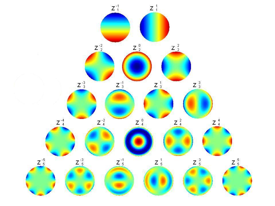
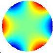
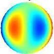
19 Zernike Polynomials
20 Wave Aberration Contour Map mm (superior-inferior) mm (right-left)
21 Breakdown of Zernike Terms Zernike term Coefficient value (microns) astig. defocus astig. trefoil coma coma trefoil spherical aberration 2 nd order 3 rd order 4 th order 5 th order
22 Diffraction
23 Diffraction Any deviation of light rays from a rectilinear path which cannot be interpreted as reflection or refraction Sommerfeld, ~ 1894
24 Fraunhofer Diffraction Also called far-field diffraction Occurs when the screen is held far from the aperture. Occurs at the focal point of a lens!
25 Diffraction and Interference diffraction causes light to bend perpendicular to the direction of the diffracting edge interference causes the diffracted light to have peaks and valleys

26 rectangular aperture square aperture

27 circular aperture Airy Disc
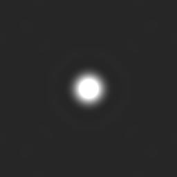
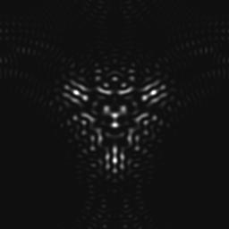
28 The Point Spread Function
29 The Point Spread Function, or PSF, is the image that an optical system forms of a point source. The point source is the most fundamental object, and forms the basis for any complex object. The PSF is analogous to the Impulse Response Function in electronics.

30 The Point Spread Function The PSF for a perfect optical system is the Airy disc, which is the Fraunhofer diffraction pattern for a circular pupil. Airy Disc
31 1.22alq = Airy Disk angle subtended at the nodal point wave q
32 As the pupil size gets larger, the Airy disc gets smaller. angle subtended at the nodal point wave PSF Airy Disk radius (minutes) pupil diameter (mm)

33 Point Spread Function vs. Pupil Size 1 mm 2 mm 3 mm 4 mm 5 mm 6 mm 7 mm
34 Small Pupil
35 Larger pupil
36 Point Spread Function vs. Pupil Size Perfect Eye 1 mm 2 mm 3 mm 4 mm 5 mm 6 mm 7 mm
37 Point Spread Function vs. Pupil Size Typical Eye 1 mm 2 mm 3 mm 4 mm pupil images followed by psfs for changing pupil size 5 mm 6 mm 7 mm
38 Demonstration Observe Your Own Point Spread Function
39 Resolution


40 Unresolved point sources Rayleigh resolution limit Resolved
41 As the pupil size gets larger, the Airy disc gets smaller. minmin angle subtended at the nodal point wa PSF Airy Disk radius (minutes) pupil diameter (mm)
42 uncorrected corrected AO image of binary star k-peg on the 3.5-m telescope at the Starfire Optical Range q l = seconds of a 3.5 About 1000 times better than the eye! min = = arc

43 Keck telescope: (10 m reflector) About 4500 times better than the eye!
44 Convolution
")
45 Convolution (,) (,) (,)PSFxyOxyIxyƒ=


46 Simulated Images 20/20 letters 20/40 letters
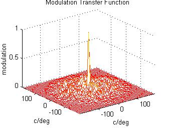
47 MTF Modulation Transfer Function

48 low medium high object: 100% contrast image contrast 1 0 spatial frequency
49 The modulation transfer function (MTF) indicates the ability of an optical system to reproduce (transfer) various levels of detail (spatial frequencies) from the object to the image. Its units are the ratio of image contrast over the object contrast as a function of spatial frequency. It is the optical contribution to the contrast sensitivity function (CSF).
50 modulation transfer MTF: Cutoff Frequency 1 mm 2 mm 4 mm 6 mm 8 mm spatial frequency (c/deg) cut-off frequency 57.3cutoffafl= Rule of thumb: cutoff frequency increases by ~30 c/d for each mm increase in pupil size
51 PTF Phase Transfer Function


52 low medium high object image phase shift spatial frequency
53 Relationships Between Wave Aberration, PSF and MTF
54 ()2(,),(,)iWxyiiPSFxyFTPxyepl-Ï =Ì Ó The PSF is the Fourier Transform (FT) of the pupil function The MTF is the amplitude component of the FT of the PSF (){},(,)xyiimtfffamplitudeftpsfxy=è Î The PTF is the phase component of the FT of the PSF (){},(,)xyiiptfffphaseftpsfxy=è Î
55
56
57


58 Adaptive Optics Flattens the Wave Aberration AO OFF AO ON
59 Conventional Metrics to Define Imagine Quality
60 Root Mean Square Root Mean Square ()()()()()21,, pupil area, wave aberratio
61 Root Mean Square: Advantage of Using Zernikes to Represent the Wavefront ()()()() RMSZZZZ--=+++ astigmatism term defocus term astigmatism term trefoil term
62 diffraction-limited PSF Strehl Ratio Strehl Ratio = eyedlhh H dl actual PSF H eye
63 Modulation Transfer Function contrast /20 20/10 Area under the MTF spatial frequency (c/deg)
64 Other Metrics Volume under the MTF Image Plane Metrics (Strehl ratio) vs Pupil Plane Metrics (eg RMS)
65 Other Optical Factors that Degrade Image Quality
66 Retinal Sampling
67 Sampling by Foveal Cones Projected Image Sampled Image 20/20 letter 5 arc minutes
68 Sampling by Foveal Cones Projected Image Sampled Image 20/5 letter 5 arc minutes
69 Nyquist Sampling Theorem
70 1 Photoreceptor Sampling >> Spatial Frequency I 0 1 I 0 nearly 100% transmitted
71 1 Photoreceptor Sampling = 2 x Spatial Frequency I 0 1 I 0 nearly 100% transmitted
72 1 Photoreceptor Sampling = Spatial Frequency I 0 1 I 0 nothing transmitted
73 Nyquist theorem: The maximum spatial frequency that can be detected is equal to _ of the sampling frequency. foveal cone spacing ~ 120 samples/deg maximum spatial frequency: 60 cycles/deg (20/10 or 6/3 acuity)
74 Thankyou!
Review of Basic Principles in Optics, Wavefront and Wavefront Error
 Review of Basic Principles in Optics, Wavefront and Wavefront Error Austin Roorda, Ph.D. University of California, Berkeley Google my name to find copies of these slides for free use and distribution Geometrical
Aberrations and Visual Performance: Part I: How aberrations affect vision
 Aberrations and Visual Performance: Part I: How aberrations affect vision Raymond A. Applegate, OD, Ph.D. Professor and Borish Chair of Optometry University of Houston Houston, TX, USA Aspects of this
Subjective Image Quality Metrics from The Wave Aberration
 Subjective Image Quality Metrics from The Wave Aberration David R. Williams William G. Allyn Professor of Medical Optics Center For Visual Science University of Rochester Commercial Relationship: Bausch
Basics Of Retinal Image Quality
 Slide 2 Basics Of Retinal Image Quality Slide 3 The optics of the eye are the first stage of vision. It is an extremely important stage but not the only stage. Slide 4 Broadly There Are Two Components
VS 212A Proseminar Optics and Dioptrics of the Eye. Austin Roorda, PhD
 VS 212A Proseminar Optics and Dioptrics of the Eye Austin Roorda, PhD Part 1: Light and Spectra Rodieck, B. The First Steps in Seeing normalized spectral absorptance Relative Spectral Absorptance 1.00
Modulation Transfer Function
 Modulation Transfer Function The Modulation Transfer Function (MTF) is a useful tool in system evaluation. t describes if, and how well, different spatial frequencies are transferred from object to image.
OPTICAL IMAGE FORMATION
 GEOMETRICAL IMAGING First-order image is perfect object (input) scaled (by magnification) version of object optical system magnification = image distance/object distance no blurring object distance image
Lecture 8. Lecture 8. r 1
 Lecture 8 Achromat Design Design starts with desired Next choose your glass materials, i.e. Find P D P D, then get f D P D K K Choose radii (still some freedom left in choice of radii for minimization
Explanation of Aberration and Wavefront
 Explanation of Aberration and Wavefront 1. What Causes Blur? 2. What is? 4. What is wavefront? 5. Hartmann-Shack Aberrometer 6. Adoption of wavefront technology David Oh 1. What Causes Blur? 2. What is?
Lecture 4: Geometrical Optics 2. Optical Systems. Images and Pupils. Rays. Wavefronts. Aberrations. Outline
 Lecture 4: Geometrical Optics 2 Outline 1 Optical Systems 2 Images and Pupils 3 Rays 4 Wavefronts 5 Aberrations Christoph U. Keller, Leiden University, keller@strw.leidenuniv.nl Lecture 4: Geometrical
Cardinal Points of an Optical System--and Other Basic Facts
 Cardinal Points of an Optical System--and Other Basic Facts The fundamental feature of any optical system is the aperture stop. Thus, the most fundamental optical system is the pinhole camera. The image
Is Aberration-Free Correction the Best Goal
 Is Aberration-Free Correction the Best Goal Stephen Burns, PhD, Jamie McLellan, Ph.D., Susana Marcos, Ph.D. The Schepens Eye Research Institute. Schepens Eye Research Institute, an affiliate of Harvard
( ) Deriving the Lens Transmittance Function. Thin lens transmission is given by a phase with unit magnitude.
 Deriving the Lens Transmittance Function. Thin lens transmission is given by a phase with unit magnitude.") Deriving the Lens Transmittance Function Thin lens transmission is given by a phase with unit magnitude. t(x, y) = exp[ jk o ]exp[ jk(n 1) (x, y) ] Find the thickness function for left half of the lens
Deriving the Lens Transmittance Function Thin lens transmission is given by a phase with unit magnitude. t(x, y) = exp[ jk o ]exp[ jk(n 1) (x, y) ] Find the thickness function for left half of the lens
Why is There a Black Dot when Defocus = 1λ?
 Why is There a Black Dot when Defocus = 1λ? W = W 020 = a 020 ρ 2 When a 020 = 1λ Sag of the wavefront at full aperture (ρ = 1) = 1λ Sag of the wavefront at ρ = 0.707 = 0.5λ Area of the pupil from ρ =
Ron Liu OPTI521-Introductory Optomechanical Engineering December 7, 2009
 Synopsis of METHOD AND APPARATUS FOR IMPROVING VISION AND THE RESOLUTION OF RETINAL IMAGES by David R. Williams and Junzhong Liang from the US Patent Number: 5,777,719 issued in July 7, 1998 Ron Liu OPTI521-Introductory
PROCEEDINGS OF SPIE. Measurement of low-order aberrations with an autostigmatic microscope
 PROCEEDINGS OF SPIE SPIEDigitalLibrary.org/conference-proceedings-of-spie Measurement of low-order aberrations with an autostigmatic microscope William P. Kuhn Measurement of low-order aberrations with
LECTURE 13 DIFFRACTION. Instructor: Kazumi Tolich
 LECTURE 13 DIFFRACTION Instructor: Kazumi Tolich Lecture 13 2 Reading chapter 33-4 & 33-6 to 33-7 Single slit diffraction Two slit interference-diffraction Fraunhofer and Fresnel diffraction Diffraction
Astronomical Observing Techniques Lecture 6: Op:cs
 Astronomical Observing Techniques Lecture 6: Op:cs Christoph U. Keller keller@strw.leidenuniv.nl Outline 1. Geometrical Op
What is Wavefront Aberration? Custom Contact Lenses For Vision Improvement Are They Feasible In A Disposable World?
 Custom Contact Lenses For Vision Improvement Are They Feasible In A Disposable World? Ian Cox, BOptom, PhD, FAAO Distinguished Research Fellow Bausch & Lomb, Rochester, NY Acknowledgements Center for Visual
A Computational Model for Predicting Visual Acuity from Wavefront Aberration Measurements
 A Computational Model for Predicting Visual Acuity from Wavefront Aberration Measurements by Azadeh Faylienejad A thesis presented to the University of Waterloo in fulfillment of the thesis requirement
Lens Design I Seminar 5
 Y. Sekman, X. Lu, H. Gross Friedrich Schiller University Jena Institute of Applied Physics Albert-Einstein-Str 15 07745 Jena Lens Design I Seminar 5 Exercise 5-1: PSF scaling (Homework) To check the Airy
Study the Effect of Lens Monochromatic Aberrations on Satellite Images Quality
 Study the Effect of Lens Monochromatic Aberrations on Satellite s Quality Eng. Mohamed Ahmed Ali* Dr. Fawzy Eltohamy* Dr.Mohamed abdelhady * Dr. Gouda I. Salama* *Department of Aircraft Electric Equipment,
Lecture 2: Geometrical Optics. Geometrical Approximation. Lenses. Mirrors. Optical Systems. Images and Pupils. Aberrations.
 Lecture 2: Geometrical Optics Outline 1 Geometrical Approximation 2 Lenses 3 Mirrors 4 Optical Systems 5 Images and Pupils 6 Aberrations Christoph U. Keller, Leiden Observatory, keller@strw.leidenuniv.nl
The Human Visual System. Lecture 1. The Human Visual System. The Human Eye. The Human Retina. cones. rods. horizontal. bipolar. amacrine.
 Lecture The Human Visual System The Human Visual System Retina Optic Nerve Optic Chiasm Lateral Geniculate Nucleus (LGN) Visual Cortex The Human Eye The Human Retina Lens rods cones Cornea Fovea Optic
Criteria for Optical Systems: Optical Path Difference How do we determine the quality of a lens system? Several criteria used in optical design
 Criteria for Optical Systems: Optical Path Difference How do we determine the quality of a lens system? Several criteria used in optical design Computer Aided Design Several CAD tools use Ray Tracing (see
PHY 431 Homework Set #5 Due Nov. 20 at the start of class
 PHY 431 Homework Set #5 Due Nov. 0 at the start of class 1) Newton s rings (10%) The radius of curvature of the convex surface of a plano-convex lens is 30 cm. The lens is placed with its convex side down
INTRODUCTION TO ABERRATIONS IN OPTICAL IMAGING SYSTEMS
 INTRODUCTION TO ABERRATIONS IN OPTICAL IMAGING SYSTEMS JOSE SASIÄN University of Arizona ШШ CAMBRIDGE Щ0 UNIVERSITY PRESS Contents Preface Acknowledgements Harold H. Hopkins Roland V. Shack Symbols 1 Introduction
Lecture 2: Geometrical Optics. Geometrical Approximation. Lenses. Mirrors. Optical Systems. Images and Pupils. Aberrations.
 Lecture 2: Geometrical Optics Outline 1 Geometrical Approximation 2 Lenses 3 Mirrors 4 Optical Systems 5 Images and Pupils 6 Aberrations Christoph U. Keller, Leiden Observatory, keller@strw.leidenuniv.nl
OPTICAL IMAGING AND ABERRATIONS
 OPTICAL IMAGING AND ABERRATIONS PARTI RAY GEOMETRICAL OPTICS VIRENDRA N. MAHAJAN THE AEROSPACE CORPORATION AND THE UNIVERSITY OF SOUTHERN CALIFORNIA SPIE O P T I C A L E N G I N E E R I N G P R E S S A
Exercise 1 - Lens bending
 Exercise 1 - Lens bending Most of the aberrations change with the bending of a lens. This is demonstrated in this exercise. a) Establish a lens with focal length f = 100 mm made of BK7 with thickness 5
DOING PHYSICS WITH MATLAB COMPUTATIONAL OPTICS. GUI Simulation Diffraction: Focused Beams and Resolution for a lens system
 DOING PHYSICS WITH MATLAB COMPUTATIONAL OPTICS GUI Simulation Diffraction: Focused Beams and Resolution for a lens system Ian Cooper School of Physics University of Sydney ian.cooper@sydney.edu.au DOWNLOAD
Vision. The eye. Image formation. Eye defects & corrective lenses. Visual acuity. Colour vision. Lecture 3.5
 Lecture 3.5 Vision The eye Image formation Eye defects & corrective lenses Visual acuity Colour vision Vision http://www.wired.com/wiredscience/2009/04/schizoillusion/ Perception of light--- eye-brain
Binocular and Scope Performance 57. Diffraction Effects
 Binocular and Scope Performance 57 Diffraction Effects The resolving power of a perfect optical system is determined by diffraction that results from the wave nature of light. An infinitely distant point
10/25/2017. Financial Disclosures. Do your patients complain of? Are you frustrated by remake after remake? What is wavefront error (WFE)?
?") Wavefront-Guided Optics in Clinic: Financial Disclosures The New Frontier November 4, 2017 Matthew J. Kauffman, OD, FAAO, FSLS STAPLE Program Soft Toric and Presbyopic Lens Education Gas Permeable Lens
Wavefront-Guided Optics in Clinic: Financial Disclosures The New Frontier November 4, 2017 Matthew J. Kauffman, OD, FAAO, FSLS STAPLE Program Soft Toric and Presbyopic Lens Education Gas Permeable Lens
ECEN 4606, UNDERGRADUATE OPTICS LAB
 ECEN 4606, UNDERGRADUATE OPTICS LAB Lab 2: Imaging 1 the Telescope Original Version: Prof. McLeod SUMMARY: In this lab you will become familiar with the use of one or more lenses to create images of distant
The Aberration Structure of the Keratoconic Eye
 The Aberration Structure of the Keratoconic Eye Geunyoung Yoon, Ph.D. Department of Ophthalmology Center for Visual Science Institute of Optics Department of Biomedical Engineering University of Rochester
Theoretical modeling and evaluation of the axial resolution of the adaptive optics scanning laser ophthalmoscope
 Journal of Biomedical Optics 9(1), 132 138 (January/February 2004) Theoretical modeling and evaluation of the axial resolution of the adaptive optics scanning laser ophthalmoscope Krishnakumar Venkateswaran
Chapters 1 & 2. Definitions and applications Conceptual basis of photogrammetric processing
 Chapters 1 & 2 Chapter 1: Photogrammetry Definitions and applications Conceptual basis of photogrammetric processing Transition from two-dimensional imagery to three-dimensional information Automation
1.1 Singlet. Solution. a) Starting setup: The two radii and the image distance is chosen as variable.
 Starting setup: The two radii and the image distance is chosen as variable.") 1 1.1 Singlet Optimize a single lens with the data λ = 546.07 nm, object in the distance 100 mm from the lens on axis only, focal length f = 45 mm and numerical aperture NA = 0.07 in the object space.
1 1.1 Singlet Optimize a single lens with the data λ = 546.07 nm, object in the distance 100 mm from the lens on axis only, focal length f = 45 mm and numerical aperture NA = 0.07 in the object space.
Early Telescopes & Geometrical Optics. C. A. Griffith, Class Notes, PTYS 521, 2016 Not for distribution.
 Early Telescopes & Geometrical Optics C. A. Griffith, Class Notes, PTYS 521, 2016 Not for distribution. 1 1.2. Image Formation Fig. 1. Snell s law indicates the bending of light at the interface of two
Applied Optics. , Physics Department (Room #36-401) , ,
 , ,") Applied Optics Professor, Physics Department (Room #36-401) 2290-0923, 019-539-0923, shsong@hanyang.ac.kr Office Hours Mondays 15:00-16:30, Wednesdays 15:00-16:30 TA (Ph.D. student, Room #36-415) 2290-0921,
Applied Optics Professor, Physics Department (Room #36-401) 2290-0923, 019-539-0923, shsong@hanyang.ac.kr Office Hours Mondays 15:00-16:30, Wednesdays 15:00-16:30 TA (Ph.D. student, Room #36-415) 2290-0921,
Optical Design with Zemax for PhD - Basics
 Optical Design with Zemax for PhD - Basics Lecture 3: Properties of optical sstems II 2013-05-30 Herbert Gross Summer term 2013 www.iap.uni-jena.de 2 Preliminar Schedule No Date Subject Detailed content
25 cm. 60 cm. 50 cm. 40 cm.
 Geometrical Optics 7. The image formed by a plane mirror is: (a) Real. (b) Virtual. (c) Erect and of equal size. (d) Laterally inverted. (e) B, c, and d. (f) A, b and c. 8. A real image is that: (a) Which
4th International Congress of Wavefront Sensing and Aberration-free Refractive Correction ADAPTIVE OPTICS FOR VISION: THE EYE S ADAPTATION TO ITS
 4th International Congress of Wavefront Sensing and Aberration-free Refractive Correction (Supplement to the Journal of Refractive Surgery; June 2003) ADAPTIVE OPTICS FOR VISION: THE EYE S ADAPTATION TO
Chapter 25. Optical Instruments
 Chapter 25 Optical Instruments Optical Instruments Analysis generally involves the laws of reflection and refraction Analysis uses the procedures of geometric optics To explain certain phenomena, the wave
OPTI 517 Image Quality. Richard Juergens
 OPTI 517 Image Quality Richard Juergens 520-577-6918 rcjuergens@msn.com Why is Image Quality Important? Resolution of detail Smaller blur sizes allow better reproduction of image details Addition of noise
Advanced Lens Design
 Advanced Lens Design Lecture 3: Aberrations I 214-11-4 Herbert Gross Winter term 214 www.iap.uni-jena.de 2 Preliminary Schedule 1 21.1. Basics Paraxial optics, imaging, Zemax handling 2 28.1. Optical systems
IMAGE SENSOR SOLUTIONS. KAC-96-1/5" Lens Kit. KODAK KAC-96-1/5" Lens Kit. for use with the KODAK CMOS Image Sensors. November 2004 Revision 2
 KODAK for use with the KODAK CMOS Image Sensors November 2004 Revision 2 1.1 Introduction Choosing the right lens is a critical aspect of designing an imaging system. Typically the trade off between image
3.0 Alignment Equipment and Diagnostic Tools:
 3.0 Alignment Equipment and Diagnostic Tools: Alignment equipment The alignment telescope and its use The laser autostigmatic cube (LACI) interferometer A pin -- and how to find the center of curvature
CHARA Collaboration Review New York 2007 CHARA Telescope Alignment
 CHARA Telescope Alignment By Laszlo Sturmann Mersenne (Cassegrain type) Telescope M2 140 mm R= 625 mm k = -1 M1/M2 provides an afocal optical system 1 m input beam and 0.125 m collimated output beam Aplanatic
Tutorial Zemax 3 Aberrations
 Tutorial Zemax 3 Aberrations 2012-08-14 3 Aberrations 1 3.1 Exercise 3-1: Strehl ratio and geometrical vs Psf spot size... 1 3.2 Exercise 3-2: Performance of an achromate... 3 3.3 Exercise 3-3: Anamorphotic
Chapter 34 The Wave Nature of Light; Interference. Copyright 2009 Pearson Education, Inc.
 Chapter 34 The Wave Nature of Light; Interference 34-7 Luminous Intensity The intensity of light as perceived depends not only on the actual intensity but also on the sensitivity of the eye at different
ORIGINAL ARTICLES. Image Metrics for Predicting Subjective Image Quality
 1040-5488/05/8205-0358/0 VOL. 82, NO. 5, PP. 358 369 OPTOMETRY AND VISION SCIENCE Copyright 2005 American Academy of Optometry ORIGINAL ARTICLES Image Metrics for Predicting Subjective Image Quality LI
12.4 Alignment and Manufacturing Tolerances for Segmented Telescopes
 330 Chapter 12 12.4 Alignment and Manufacturing Tolerances for Segmented Telescopes Similar to the JWST, the next-generation large-aperture space telescope for optical and UV astronomy has a segmented
Predicting the Performance of Space Coronagraphs. John Krist (JPL) 17 August st International Vortex Workshop
 17 August st International Vortex Workshop") Predicting the Performance of Space Coronagraphs John Krist (JPL) 17 August 2016 1 st International Vortex Workshop Determine the Reality of a Coronagraph through End-to-End Modeling Use End-to-End modeling
Predicting the Performance of Space Coronagraphs John Krist (JPL) 17 August 2016 1 st International Vortex Workshop Determine the Reality of a Coronagraph through End-to-End Modeling Use End-to-End modeling
Adaptive Optics. Adaptive optics for imaging. Adaptive optics to improve. Ocular High order Aberrations (HOA)
") Effect of Adaptive Optics Correction on Visual Performance and Accommodation Adaptive optics for imaging Astromomy Retinal imaging Since 977, Hardy et al, JOSA A Since 989, Dreher et al. Appl Opt Susana
Effect of Adaptive Optics Correction on Visual Performance and Accommodation Adaptive optics for imaging Astromomy Retinal imaging Since 977, Hardy et al, JOSA A Since 989, Dreher et al. Appl Opt Susana
Imaging and Aberration Theory
 Imaging and Aberration Theory Lecture 7: Distortion and coma 2014-12-11 Herbert Gross Winter term 2014 www.iap.uni-jena.de 2 Preliminary time schedule 1 30.10. Paraxial imaging paraxial optics, fundamental
Diffraction. modern investigations date from Augustin Fresnel
 Diffraction Diffraction controls the detail you can see in optical instruments, makes holograms, diffraction gratings and much else possible, explains some natural phenomena Diffraction was discovered
PHYSICS. Chapter 35 Lecture FOR SCIENTISTS AND ENGINEERS A STRATEGIC APPROACH 4/E RANDALL D. KNIGHT
 PHYSICS FOR SCIENTISTS AND ENGINEERS A STRATEGIC APPROACH 4/E Chapter 35 Lecture RANDALL D. KNIGHT Chapter 35 Optical Instruments IN THIS CHAPTER, you will learn about some common optical instruments and
Modulation Transfer Function
 Modulation Transfer Function The resolution and performance of an optical microscope can be characterized by a quantity known as the modulation transfer function (MTF), which is a measurement of the microscope's
J. C. Wyant Fall, 2012 Optics Optical Testing and Testing Instrumentation
 J. C. Wyant Fall, 2012 Optics 513 - Optical Testing and Testing Instrumentation Introduction 1. Measurement of Paraxial Properties of Optical Systems 1.1 Thin Lenses 1.1.1 Measurements Based on Image Equation
VATT Optical Performance During 98 Oct as Measured with an Interferometric Hartmann Wavefront Sensor
 VATT Optical Performance During 98 Oct as Measured with an Interferometric Hartmann Wavefront Sensor S. C. West, D. Fisher Multiple Mirror Telescope Observatory M. Nelson Vatican Advanced Technology Telescope
OPTICAL SYSTEMS OBJECTIVES
 101 L7 OPTICAL SYSTEMS OBJECTIVES Aims Your aim here should be to acquire a working knowledge of the basic components of optical systems and understand their purpose, function and limitations in terms
Big League Cryogenics and Vacuum The LHC at CERN
 Big League Cryogenics and Vacuum The LHC at CERN A typical astronomical instrument must maintain about one cubic meter at a pressure of
Normal Wavefront Error as a Function of Age and Pupil Size
 RAA Normal Wavefront Error as a Function of Age and Pupil Size Raymond A. Applegate, OD, PhD Borish Chair of Optometry Director of the Visual Optics Institute College of Optometry University of Houston
Evaluation of Performance of the Toronto Ultra-Cold Atoms Laboratory s Current Axial Imaging System
 Page 1 5/7/2007 Evaluation of Performance of the Toronto Ultra-Cold Atoms Laboratory s Current Axial Imaging System Vincent Kan May 7, 2007 University of Toronto Department of Physics Supervisor: Prof.
Supplemental Materials. Section 25. Aberrations
 OTI-201/202 Geometrical and Instrumental Optics 25-1 Supplemental Materials Section 25 Aberrations Aberrations of the Rotationally Symmetric Optical System First-order or paraxial systems are ideal optical
Aberrations and adaptive optics for biomedical microscopes
 Aberrations and adaptive optics for biomedical microscopes Martin Booth Department of Engineering Science And Centre for Neural Circuits and Behaviour University of Oxford Outline Rays, wave fronts and
Reflectors vs. Refractors
 1 Telescope Types - Telescopes collect and concentrate light (which can then be magnified, dispersed as a spectrum, etc). - In the end it is the collecting area that counts. - There are two primary telescope
WaveMaster IOL. Fast and Accurate Intraocular Lens Tester
 WaveMaster IOL Fast and Accurate Intraocular Lens Tester INTRAOCULAR LENS TESTER WaveMaster IOL Fast and accurate intraocular lens tester WaveMaster IOL is an instrument providing real time analysis of
High resolution extended depth of field microscopy using wavefront coding
 High resolution extended depth of field microscopy using wavefront coding Matthew R. Arnison *, Peter Török #, Colin J. R. Sheppard *, W. T. Cathey +, Edward R. Dowski, Jr. +, Carol J. Cogswell *+ * Physical
Today. next week. MIT 2.71/ /04/09 wk13-a- 1
 Today Spatially coherent and incoherent imaging with a single lens re-derivation of the single-lens imaging condition ATF/OTF/PSF and the Numerical Aperture resolution in optical systems pupil engineering
WaveMaster IOL. Fast and accurate intraocular lens tester
 WaveMaster IOL Fast and accurate intraocular lens tester INTRAOCULAR LENS TESTER WaveMaster IOL Fast and accurate intraocular lens tester WaveMaster IOL is a new instrument providing real time analysis
Physics Chapter Review Chapter 25- The Eye and Optical Instruments Ethan Blitstein
 Physics Chapter Review Chapter 25- The Eye and Optical Instruments Ethan Blitstein The Human Eye As light enters through the human eye it first passes through the cornea (a thin transparent membrane of
(495) (495)
 (495)") МЕДТЕХНИКА-СТОЛИЦА (495) 902-59-26 (495) 518-55-99 127 238, г. Москва, Дмитровское ш. 85 ATLAS Corneal Topography Product Overview Model 9000 ATLAS Model 9000 Overview Next-generation corneal topography
МЕДТЕХНИКА-СТОЛИЦА (495) 902-59-26 (495) 518-55-99 127 238, г. Москва, Дмитровское ш. 85 ATLAS Corneal Topography Product Overview Model 9000 ATLAS Model 9000 Overview Next-generation corneal topography
Multi aperture coherent imaging IMAGE testbed
 Multi aperture coherent imaging IMAGE testbed Nick Miller, Joe Haus, Paul McManamon, and Dave Shemano University of Dayton LOCI Dayton OH 16 th CLRC Long Beach 20 June 2011 Aperture synthesis (part 1 of
EE-527: MicroFabrication
 EE-57: MicroFabrication Exposure and Imaging Photons white light Hg arc lamp filtered Hg arc lamp excimer laser x-rays from synchrotron Electrons Ions Exposure Sources focused electron beam direct write
Index. B Back focal length, 12 Beam expander, 35 Berek, Max, 244 Binary phase grating, 326 Buried surface, 131,
 About the Author The author studied Technical Physics at the Technical University of Delft, The Netherlands. He obtained a master s degree in 1965 with a thesis on the fabrication of lasers. After military
Experiment 1: Fraunhofer Diffraction of Light by a Single Slit
 Experiment 1: Fraunhofer Diffraction of Light by a Single Slit Purpose 1. To understand the theory of Fraunhofer diffraction of light at a single slit and at a circular aperture; 2. To learn how to measure
Some of the important topics needed to be addressed in a successful lens design project (R.R. Shannon: The Art and Science of Optical Design)
") Lens design Some of the important topics needed to be addressed in a successful lens design project (R.R. Shannon: The Art and Science of Optical Design) Focal length (f) Field angle or field size F/number
Lens design Some of the important topics needed to be addressed in a successful lens design project (R.R. Shannon: The Art and Science of Optical Design) Focal length (f) Field angle or field size F/number
BEAM HALO OBSERVATION BY CORONAGRAPH
 BEAM HALO OBSERVATION BY CORONAGRAPH T. Mitsuhashi, KEK, TSUKUBA, Japan Abstract We have developed a coronagraph for the observation of the beam halo surrounding a beam. An opaque disk is set in the beam
Optical Design of an Off-axis Five-mirror-anastigmatic Telescope for Near Infrared Remote Sensing
 Journal of the Optical Society of Korea Vol. 16, No. 4, December 01, pp. 343-348 DOI: http://dx.doi.org/10.3807/josk.01.16.4.343 Optical Design of an Off-axis Five-mirror-anastigmatic Telescope for Near
Handbook of Optical Systems
 Handbook of Optical Systems Edited by Herbert Gross Volume 3: Aberration Theory and Correction of Optical Systems Herbert Cross, Hannfried Zügge, Martin Peschka, Fritz Blechinger BICENTENNIAL BICENTENNIA
Telescopes and their configurations. Quick review at the GO level
 Telescopes and their configurations Quick review at the GO level Refraction & Reflection Light travels slower in denser material Speed depends on wavelength Image Formation real Focal Length (f) : Distance
Chapter Ray and Wave Optics
 109 Chapter Ray and Wave Optics 1. An astronomical telescope has a large aperture to [2002] reduce spherical aberration have high resolution increase span of observation have low dispersion. 2. If two
Study on Imaging Quality of Water Ball Lens
 2017 2nd International Conference on Mechatronics and Information Technology (ICMIT 2017) Study on Imaging Quality of Water Ball Lens Haiyan Yang1,a,*, Xiaopan Li 1,b, 1,c Hao Kong, 1,d Guangyang Xu and1,eyan
MMTO Technical Memorandum #03-1
 MMTO Technical Memorandum #03-1 Fall 2002 f/9 optical performance of the 6.5m MMT analyzed with the top box Shack-Hartmann wavefront sensor S. C. West January 2003 Fall 2002 f/9 optical performance of
R.B.V.R.R. WOMEN S COLLEGE (AUTONOMOUS) Narayanaguda, Hyderabad.
 Narayanaguda, Hyderabad.") R.B.V.R.R. WOMEN S COLLEGE (AUTONOMOUS) Narayanaguda, Hyderabad. DEPARTMENT OF PHYSICS QUESTION BANK FOR SEMESTER III PAPER III OPTICS UNIT I: 1. MATRIX METHODS IN PARAXIAL OPTICS 2. ABERATIONS UNIT II
R.B.V.R.R. WOMEN S COLLEGE (AUTONOMOUS) Narayanaguda, Hyderabad. DEPARTMENT OF PHYSICS QUESTION BANK FOR SEMESTER III PAPER III OPTICS UNIT I: 1. MATRIX METHODS IN PARAXIAL OPTICS 2. ABERATIONS UNIT II
INFRARED IMAGING-PASSIVE THERMAL COMPENSATION VIA A SIMPLE PHASE MASK
 Romanian Reports in Physics, Vol. 65, No. 3, P. 700 710, 2013 Dedicated to Professor Valentin I. Vlad s 70 th Anniversary INFRARED IMAGING-PASSIVE THERMAL COMPENSATION VIA A SIMPLE PHASE MASK SHAY ELMALEM
ECEG105/ECEU646 Optics for Engineers Course Notes Part 4: Apertures, Aberrations Prof. Charles A. DiMarzio Northeastern University Fall 2008
 ECEG105/ECEU646 Optics for Engineers Course Notes Part 4: Apertures, Aberrations Prof. Charles A. DiMarzio Northeastern University Fall 2008 July 2003+ Chuck DiMarzio, Northeastern University 11270-04-1
GEOMETRICAL OPTICS AND OPTICAL DESIGN
 GEOMETRICAL OPTICS AND OPTICAL DESIGN Pantazis Mouroulis Associate Professor Center for Imaging Science Rochester Institute of Technology John Macdonald Senior Lecturer Physics Department University of
Introduction to aberrations
 Introduction to aberrations Lecture 8 Image and aberration evaluation 1 Aberrations and image: Aberration theory Aberration evaluation Image formation Image evaluation Geometrical and physical theories
Hartmann wavefront sensing Beamline alignment
 Hartmann wavefront sensing Beamline alignment Guillaume Dovillaire SOS Trieste October 4th, 2016 G. Dovillaire M COM PPT 2016.01 GD 1 SOS Trieste October 4th, 2016 G. Dovillaire M COM PPT 2016.01 GD 2
Geometric optics & aberrations
 Geometric optics & aberrations Department of Astrophysical Sciences University AST 542 http://www.northerneye.co.uk/ Outline Introduction: Optics in astronomy Basics of geometric optics Paraxial approximation
Be aware that there is no universal notation for the various quantities.
 Fourier Optics v2.4 Ray tracing is limited in its ability to describe optics because it ignores the wave properties of light. Diffraction is needed to explain image spatial resolution and contrast and
Tutorial Zemax 8: Correction II
 Tutorial Zemax 8: Correction II 2012-10-11 8 Correction II 1 8.1 High-NA Collimator... 1 8.2 Zoom-System... 6 8.3 New Achromate and wide field system... 11 8 Correction II 8.1 High-NA Collimator An achromatic
Lens Design I. Lecture 5: Advanced handling I Herbert Gross. Summer term
 Lens Design I Lecture 5: Advanced handling I 2018-05-17 Herbert Gross Summer term 2018 www.iap.uni-jena.de 2 Preliminary Schedule - Lens Design I 2018 1 12.04. Basics 2 19.04. Properties of optical systems
Fabrication of 6.5 m f/1.25 Mirrors for the MMT and Magellan Telescopes
 Fabrication of 6.5 m f/1.25 Mirrors for the MMT and Magellan Telescopes H. M. Martin, R. G. Allen, J. H. Burge, L. R. Dettmann, D. A. Ketelsen, W. C. Kittrell, S. M. Miller and S. C. West Steward Observatory,
Exercises Advanced Optical Design Part 5 Solutions
 2014-12-09 Manuel Tessmer M.Tessmer@uni-jena.dee Minyi Zhong minyi.zhong@uni-jena.de Herbert Gross herbert.gross@uni-jena.de Friedrich Schiller University Jena Institute of Applied Physics Albert-Einstein-Str.
In recent years there has been an explosion of
 Line of Sight and Alternative Representations of Aberrations of the Eye Stanley A. Klein, PhD; Daniel D. Garcia, PhD ABSTRACT Several methods for representing pupil plane aberrations based on wavefront