Tutorial Zemax 3 Aberrations
|
|
|
- Samantha Whitehead
- 5 years ago
- Views:
Transcription

1 Tutorial Zemax 3 Aberrations Aberrations Exercise 3-1: Strehl ratio and geometrical vs Psf spot size Exercise 3-2: Performance of an achromate Exercise 3-3: Anamorphotic Diode collimator Aberrations 3.1 Exercise 3-1: Strehl ratio and geometrical vs Psf spot size A single lens made of K5 with focal length f = 25 mm and thickness d = 5 mm is illuminated by a diverging beam with numerical aperture NA = 0.1. After the lens the light should be collimated. If the collimated beam is refocussed without further aberrations, the point spread function is not diffraction limited. a) Calculate the accurate Strehl ratio, the estimated Strehl ratio and the geometrical and diffraction encircled energy inside the ideal Airy diameter. b) If now the numerical aperture is reduced, the Marechal estimation becomes better. Calculate the largest NA, for which the relative error is smaller then 2%. What amount for geometrical and diffraction encircled energy is inside the Airy diameter is obtained here? Solution: a) System data and layout: b) If the numerical aperture is changed, the following steps are performed: 1. Reduce NA 2. Determine the Airy diameter out of the spot diagram window 3. Set the apertur in the image plane exactly to the Airy value 4. Calculate the estimated Strel ratio from the Zernike window 5. Calculate the accurate Strehl ratio from the Huygens PSF window with appropriate sampling 6. Calculate the geometrical encircled energy by the footprint diagram (with option: delete vignetted) 7. Calculate the diffraction encircled energy by the text output of the EE window. Then the following table is obtained: NA Strehl exact Strehl estimated relative error Airy radius geometrical EE inside diffraction EE inside


2 2 Airy Airy The relative error of the estimated Strehl ratio is smaller than 2% for NA < Here the geometrical encirceld energy is 45%, the diffraction calculated encircled energy 55%.
 Calculate the Seidel surface contributions of the system in the desired orientation and for the reversed lens.")
 Setup (Melles Griot, AAP-100.0-25.4) The numerical aperture is NA = 0.107.")
3 3 3.2 Exercise 3-2: Performance of an achromate Load a classical achromate out of a vendor catalog with focal length f = 100 mm. a) What is the numerical aperture of the system in the image side? Is the system diffraction limited? b) Calculate the Seidel surface contributions of the system in the desired orientation and for the reversed lens. c) Determine the range of finite field angles, for which the original achromate is diffraction limited, if 546 nm and a reduced aperture diameter of 15 mm is considered. Solution: a) Setup (Melles Griot, AAP ) The numerical aperture is NA = The system is diffraction limited for wavelength > 608 nm (rms vs wavelength, Strehl criterion, 9 rays, 100 wavelengths): b) Seidel aberration bar chart for the original and the reversed system:

4 4 It is seen, that the the system is quite bad for the reversed lens. Therefore the catalog component should be used only with incoming collimated light. c) With the rms-menu vs. field size and the Strehl ratio criterion with more rays, we get the following drawing after a quick focus for the axis point only: It can be seen, that the diffraction limit is violated for field angles w > 1.1.

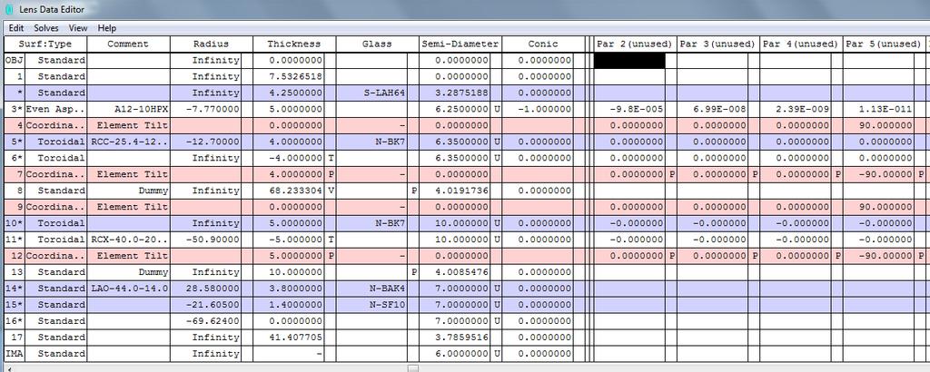
5 5 3.3 Exercise 3-3: Anamorphotic Diode collimator A semiconductor diode with wavelength 650 nm and the divergence / aperture values 0.4 / 0.1 in the fast ans slow axis respectively should be collimated in a circular beam with a diameter of approximarely 8 mm. The collimated beam is now focussed into a fiber with numerical aperture of NA = 0.1. semiconductor diode NA y = 0.4 NA x = 0.1 = 650 nm L2 cylindrical lens circular beam D = 8 mm L4 focussing lens fiber NA = 0.1 L1 L3 aspherical cylindrical lens collimator fast axis Find a solution for this problem with only available catalog lenses. Is the setup diffraction limited? Explain the shape of the residual spot pattern. What are the reasons for the residual aberrations in the system? What can be done to further improved the result? Discuss possible steps to get a shorter system. What are the consequences of a compact layout? Solution If the desired beam diameter after the collimation of the fast axis is 8 mm, the focal length of the first lens is f D/ 2/ NAy 10mm Since the numerical aperture of the fast axis is high, it is recommended to use an aspherical collimator lens, which is corrected for spherical aberration on axis. If such a lens is found in the lens catalogs, it must be considered: 1. the lens should be used without cover glas plate 2. if a working wavelength near to the 650 nm is found, it is an advantage Possible solution: Catalog Asphericon, lens with the No A12-10HPX Necessary steps to process this lens: 1. load the lens 2. turn around 3. set NA to 0.4 and vignetting factors in field menu to VCX = 0.75
 A foorprint diagram shows")

6 6 4. change wavelength to 650 nm 5. optimize first distance to collimate this wavelength (default merit function, with criterion: direction cosines) A foorprint diagram shows the elliptical beam cross section behind the lens. In the next step, a Galilean telescope with factor = 4 must be found to enlarge the diameter of the x- section to the same value as in the y-section. First a negative cylindrical lens with a rather short focal length must be found. Possible solution: Lens with 1 inch negative focal length in the catalog of Melles Griot: RCC C


7 7 The lens is inserted behind the collimating asphere and rotated around the x-axis by 90 to work in the x- section. The distance to the collimator is not very relevant and is fixed to be 5 mm. For a Galiean telescope with factor 4, the second lens must have a focal length of 4x25.1 mm = mm. In the same lens catalog one can found the following lens: RCX C

8 8 The lens is inserted, turned around to get a better performance and also tilted by 90 in the azimuth. A first guess gives a distance of =75 mm between the telescoipe lenses to get a collimated x-section. But from the spot diagram with direction cosine option it is seen, that the angle distribution is not equal in both sections. Due to the finite positions of the principal planes of the lenses, the distance must be optimized with an angle criterion default merit function. Spot diagram before and aftre this focussing operation with the same scale: The foorprint diagram now shows a rather curcular cross section. The residual error can be neglected and comes from the fact, that for this wavelengths, the catalog focal lengths are not exact. The data are now the following:


9 9 To focus the beam into a fiber with numerical aperture 0.1, the focal length must be not smaller than f = 4.32 mm / 0.1 = 43.2 mm. A lens of approximately this size can be found in the catalog of Melles Griot as an achromate. This helps in getting a better correction: LAO This lens is inserted to complete the system. Finally the last distance is optimized to get a minimal spot size. It is seen, that the spot is nearly diffraction limited.
10 10
Lens Design I Seminar 5
 Y. Sekman, X. Lu, H. Gross Friedrich Schiller University Jena Institute of Applied Physics Albert-Einstein-Str 15 07745 Jena Lens Design I Seminar 5 Exercise 5-1: PSF scaling (Homework) To check the Airy
1.1 Singlet. Solution. a) Starting setup: The two radii and the image distance is chosen as variable.
 Starting setup: The two radii and the image distance is chosen as variable.") 1 1.1 Singlet Optimize a single lens with the data λ = 546.07 nm, object in the distance 100 mm from the lens on axis only, focal length f = 45 mm and numerical aperture NA = 0.07 in the object space.
1 1.1 Singlet Optimize a single lens with the data λ = 546.07 nm, object in the distance 100 mm from the lens on axis only, focal length f = 45 mm and numerical aperture NA = 0.07 in the object space.
Tutorial Zemax 8: Correction II
 Tutorial Zemax 8: Correction II 2012-10-11 8 Correction II 1 8.1 High-NA Collimator... 1 8.2 Zoom-System... 6 8.3 New Achromate and wide field system... 11 8 Correction II 8.1 High-NA Collimator An achromatic
Exercise 1 - Lens bending
 Exercise 1 - Lens bending Most of the aberrations change with the bending of a lens. This is demonstrated in this exercise. a) Establish a lens with focal length f = 100 mm made of BK7 with thickness 5
Exercises Advanced Optical Design Part 5 Solutions
 2014-12-09 Manuel Tessmer M.Tessmer@uni-jena.dee Minyi Zhong minyi.zhong@uni-jena.de Herbert Gross herbert.gross@uni-jena.de Friedrich Schiller University Jena Institute of Applied Physics Albert-Einstein-Str.
Solution of Exercises Lecture Optical design with Zemax Part 6
 2013-06-17 Prof. Herbert Gross Friedrich Schiller University Jena Institute of Applied Physics Albert-Einstein-Str 15 07745 Jena Solution of Exercises Lecture Optical design with Zemax Part 6 6 Illumination
Lens Design I Seminar 1
 Xiang Lu, Ralf Hambach Friedrich Schiller University Jena Institute of Applied Physics Albert-Einstein-Str 15 07745 Jena Lens Design I Seminar 1 Warm-Up (20min) Setup a single, symmetric, biconvex lens
Tutorial Zemax Introduction 1
 Tutorial Zemax Introduction 1 2012-07-17 1 Introduction 1 1.1 Exercise 1-1: Stair-mirror-setup... 1 1.2 Exercise 1-2: Symmetrical 4f-system... 5 1 Introduction 1.1 Exercise 1-1: Stair-mirror-setup Setup
Solution of Exercises Lecture Optical design with Zemax for PhD Part 8
 2013-06-17 Prof. Herbert Gross Friedrich Schiller University Jena Institute of Applied Physics Albert-Einstein-Str 15 07745 Jena Solution of Exercises Lecture Optical design with Zemax for PhD Part 8 8.1
Lens Design I. Lecture 5: Advanced handling I Herbert Gross. Summer term
 Lens Design I Lecture 5: Advanced handling I 2018-05-17 Herbert Gross Summer term 2018 www.iap.uni-jena.de 2 Preliminary Schedule - Lens Design I 2018 1 12.04. Basics 2 19.04. Properties of optical systems
Optical Design with Zemax
 Optical Design with Zemax Lecture 9: Advanced handling 2014-06-13 Herbert Gross Sommer term 2014 www.iap.uni-jena.de 2 Preliminary Schedule 1 11.04. Introduction 2 25.04. Properties of optical systems
Optical Design with Zemax for PhD - Basics
 Optical Design with Zemax for PhD - Basics Lecture 3: Properties of optical sstems II 2013-05-30 Herbert Gross Summer term 2013 www.iap.uni-jena.de 2 Preliminar Schedule No Date Subject Detailed content
Solutions: Lens Design I Part 2. Exercise 2-1: Apertures, stops and vignetting
 2016-04-25 Prof. Herbert Gross Mateusz Oleszko, Norman G. Worku Friedrich Schiller University Jena Institute of Applied Physics Albert-Einstein-Str 15 07745 Jena Solutions: Lens Design I Part 2 Exercise
Lens Design I. Lecture 3: Properties of optical systems II Herbert Gross. Summer term
 Lens Design I Lecture 3: Properties of optical systems II 205-04-8 Herbert Gross Summer term 206 www.iap.uni-jena.de 2 Preliminary Schedule 04.04. Basics 2.04. Properties of optical systrems I 3 8.04.
Lens Design I. Lecture 5: Advanced handling I Herbert Gross. Summer term
 Lens Design I Lecture 5: Advanced handling I 2015-05-11 Herbert Gross Summer term 2015 www.iap.uni-jena.de 2 Preliminary Schedule 1 13.04. Basics 2 20.04. Properties of optical systrems I 3 27.05. Properties
Lens Design I. Lecture 3: Properties of optical systems II Herbert Gross. Summer term
 Lens Design I Lecture 3: Properties of optical systems II 207-04-20 Herbert Gross Summer term 207 www.iap.uni-jena.de 2 Preliminary Schedule - Lens Design I 207 06.04. Basics 2 3.04. Properties of optical
Optical Design with Zemax
 Optical Design with Zemax Lecture : Correction II 3--9 Herbert Gross Summer term www.iap.uni-jena.de Correction II Preliminary time schedule 6.. Introduction Introduction, Zemax interface, menues, file
Optical Design with Zemax for PhD
 Optical Design with Zemax for PhD Lecture 7: Optimization II 26--2 Herbert Gross Winter term 25 www.iap.uni-jena.de 2 Preliminary Schedule No Date Subject Detailed content.. Introduction 2 2.2. Basic Zemax
Lecture 2: Geometrical Optics. Geometrical Approximation. Lenses. Mirrors. Optical Systems. Images and Pupils. Aberrations.
 Lecture 2: Geometrical Optics Outline 1 Geometrical Approximation 2 Lenses 3 Mirrors 4 Optical Systems 5 Images and Pupils 6 Aberrations Christoph U. Keller, Leiden Observatory, keller@strw.leidenuniv.nl
Lens Design II Seminar 6 (Solutions)
") 2017-01-04 Prof. Herbert Gross Yi Zhong, Norman G. Worku Friedrich Schiller University Jena Institute of Applied Physics Albert-Einstein-Str 15 07745 Jena Lens Design II Seminar 6 (Solutions) 6.1. Correction
2017-01-04 Prof. Herbert Gross Yi Zhong, Norman G. Worku Friedrich Schiller University Jena Institute of Applied Physics Albert-Einstein-Str 15 07745 Jena Lens Design II Seminar 6 (Solutions) 6.1. Correction
Tutorial Zemax 9: Physical optical modelling I
 Tutorial Zemax 9: Physical optical modelling I 2012-11-04 9 Physical optical modelling I 1 9.1 Gaussian Beams... 1 9.2 Physical Beam Propagation... 3 9.3 Polarization... 7 9.4 Polarization II... 11 9 Physical
Lecture 2: Geometrical Optics. Geometrical Approximation. Lenses. Mirrors. Optical Systems. Images and Pupils. Aberrations.
 Lecture 2: Geometrical Optics Outline 1 Geometrical Approximation 2 Lenses 3 Mirrors 4 Optical Systems 5 Images and Pupils 6 Aberrations Christoph U. Keller, Leiden Observatory, keller@strw.leidenuniv.nl
Advanced Lens Design
 Advanced Lens Design Lecture 3: Aberrations I 214-11-4 Herbert Gross Winter term 214 www.iap.uni-jena.de 2 Preliminary Schedule 1 21.1. Basics Paraxial optics, imaging, Zemax handling 2 28.1. Optical systems
Lecture 4: Geometrical Optics 2. Optical Systems. Images and Pupils. Rays. Wavefronts. Aberrations. Outline
 Lecture 4: Geometrical Optics 2 Outline 1 Optical Systems 2 Images and Pupils 3 Rays 4 Wavefronts 5 Aberrations Christoph U. Keller, Leiden University, keller@strw.leidenuniv.nl Lecture 4: Geometrical
Performance Factors. Technical Assistance. Fundamental Optics
 Performance Factors After paraxial formulas have been used to select values for component focal length(s) and diameter(s), the final step is to select actual lenses. As in any engineering problem, this
Lens Design II. Lecture 2: Structural modifications Herbert Gross. Winter term
 Lens Design II Lecture 2: Structural modifications 26--26 Herbert Gross Winter term 26 www.iap.uni-jena.de 2 Preliminary Schedule 9.. Aberrations and optimization Repetition 2 26.. Structural modifications
Sequential Ray Tracing. Lecture 2
 Sequential Ray Tracing Lecture 2 Sequential Ray Tracing Rays are traced through a pre-defined sequence of surfaces while travelling from the object surface to the image surface. Rays hit each surface once
Lens Design I. Lecture 10: Optimization II Herbert Gross. Summer term
 Lens Design I Lecture : Optimization II 5-6- Herbert Gross Summer term 5 www.iap.uni-jena.de Preliminary Schedule 3.. Basics.. Properties of optical systrems I 3 7.5..5. Properties of optical systrems
StockOptics. CATALOG 2018 Europe
 StockOptics CATALOG 2018 Europe Dear asphericon customer Within the StockOptics product line, you can choose from an extensive portfolio of precision-polished aspheric lenses, cylinders and axicons. Benefit
Lens Design I. Lecture 10: Optimization II Herbert Gross. Summer term
 Lens Design I Lecture : Optimization II 8-6- Herbert Gross Summer term 8 www.iap.uni-jena.de Preliminary Schedule - Lens Design I 8.4. Basics 9.4. Properties of optical systems I 3 6.4. Properties of optical
3.0 Alignment Equipment and Diagnostic Tools:
 3.0 Alignment Equipment and Diagnostic Tools: Alignment equipment The alignment telescope and its use The laser autostigmatic cube (LACI) interferometer A pin -- and how to find the center of curvature
Tolerancing in Zemax. Lecture 4
 Tolerancing in Zemax Lecture 4 Objectives: Lecture 4 At the end of this lecture you should: 1. Understand the reason for tolerancing and its relation to typical manufacturing errors 2. Be able to perform
Some of the important topics needed to be addressed in a successful lens design project (R.R. Shannon: The Art and Science of Optical Design)
") Lens design Some of the important topics needed to be addressed in a successful lens design project (R.R. Shannon: The Art and Science of Optical Design) Focal length (f) Field angle or field size F/number
Lens design Some of the important topics needed to be addressed in a successful lens design project (R.R. Shannon: The Art and Science of Optical Design) Focal length (f) Field angle or field size F/number
Advanced Lens Design
 Advanced Lens Design Lecture 4: Optimization III 2013-11-04 Herbert Gross Winter term 2013 www.iap.uni-jena.de 2 Preliminary Schedule 1 15.10. Introduction Paraxial optics, ideal lenses, optical systems,
ECEN 4606, UNDERGRADUATE OPTICS LAB
 ECEN 4606, UNDERGRADUATE OPTICS LAB Lab 2: Imaging 1 the Telescope Original Version: Prof. McLeod SUMMARY: In this lab you will become familiar with the use of one or more lenses to create images of distant
Chapter Ray and Wave Optics
 109 Chapter Ray and Wave Optics 1. An astronomical telescope has a large aperture to [2002] reduce spherical aberration have high resolution increase span of observation have low dispersion. 2. If two
October 7, Peter Cheimets Smithsonian Astrophysical Observatory 60 Garden Street, MS 5 Cambridge, MA Dear Peter:
 October 7, 1997 Peter Cheimets Smithsonian Astrophysical Observatory 60 Garden Street, MS 5 Cambridge, MA 02138 Dear Peter: This is the report on all of the HIREX analysis done to date, with corrections
Using Stock Optics. ECE 5616 Curtis
 Using Stock Optics What shape to use X & Y parameters Please use achromatics Please use camera lens Please use 4F imaging systems Others things Data link Stock Optics Some comments Advantages Time and
Chapter 3. Introduction to Zemax. 3.1 Introduction. 3.2 Zemax
 Chapter 3 Introduction to Zemax 3.1 Introduction Ray tracing is practical only for paraxial analysis. Computing aberrations and diffraction effects are time consuming. Optical Designers need some popular
Cardinal Points of an Optical System--and Other Basic Facts
 Cardinal Points of an Optical System--and Other Basic Facts The fundamental feature of any optical system is the aperture stop. Thus, the most fundamental optical system is the pinhole camera. The image
AST Lab exercise: aberrations
 AST2210 - Lab exercise: aberrations 1 Introduction This lab exercise will take you through the most common types of aberrations. 2 Chromatic aberration Chromatic aberration causes lens to have dierent
OPTICAL IMAGING AND ABERRATIONS
 OPTICAL IMAGING AND ABERRATIONS PARTI RAY GEOMETRICAL OPTICS VIRENDRA N. MAHAJAN THE AEROSPACE CORPORATION AND THE UNIVERSITY OF SOUTHERN CALIFORNIA SPIE O P T I C A L E N G I N E E R I N G P R E S S A
Lecture 3: Geometrical Optics 1. Spherical Waves. From Waves to Rays. Lenses. Chromatic Aberrations. Mirrors. Outline
 Lecture 3: Geometrical Optics 1 Outline 1 Spherical Waves 2 From Waves to Rays 3 Lenses 4 Chromatic Aberrations 5 Mirrors Christoph U. Keller, Leiden Observatory, keller@strw.leidenuniv.nl Lecture 3: Geometrical
COLLIMATORS AND FOCUSERS RECEPTACLE STYLE
 COLLIMATORS AND FOCUSERS RECEPTACLE STYLE FEATURES: High power handling Rugged and compact design Low insertion loss Wide wavelength range 200-2100 nm Wide range of beam diameters GRIN, aspheric, achromatic,
Beam expansion standard concepts re-interpreted
 Beam expansion standard concepts re-interpreted Ulrike Fuchs (Ph.D.), Sven R. Kiontke asphericon GmbH Stockholmer Str. 9 07743 Jena, Germany Tel: +49-3641-3100500 Introduction Everyday work in an optics
Image Formation. Light from distant things. Geometrical optics. Pinhole camera. Chapter 36
 Light from distant things Chapter 36 We learn about a distant thing from the light it generates or redirects. The lenses in our eyes create images of objects our brains can process. This chapter concerns
Optical Components for Laser Applications. Günter Toesko - Laserseminar BLZ im Dezember
 Günter Toesko - Laserseminar BLZ im Dezember 2009 1 Aberrations An optical aberration is a distortion in the image formed by an optical system compared to the original. It can arise for a number of reasons
Optical System Design
 Phys 531 Lecture 12 14 October 2004 Optical System Design Last time: Surveyed examples of optical systems Today, discuss system design Lens design = course of its own (not taught by me!) Try to give some
Lens Design II. Lecture 3: Aspheres Herbert Gross. Winter term
 Lens Design II Lecture 3: Aspheres 6-- Herbert Gross Winter term 6 www.iap.uni-jena.de Preliminar Schedule 9.. Aberrations and optimiation Repetition 6.. Structural modifications Zero operands, lens splitting,
Why is There a Black Dot when Defocus = 1λ?
 Why is There a Black Dot when Defocus = 1λ? W = W 020 = a 020 ρ 2 When a 020 = 1λ Sag of the wavefront at full aperture (ρ = 1) = 1λ Sag of the wavefront at ρ = 0.707 = 0.5λ Area of the pupil from ρ =
GEOMETRICAL OPTICS Practical 1. Part I. BASIC ELEMENTS AND METHODS FOR CHARACTERIZATION OF OPTICAL SYSTEMS
 GEOMETRICAL OPTICS Practical 1. Part I. BASIC ELEMENTS AND METHODS FOR CHARACTERIZATION OF OPTICAL SYSTEMS Equipment and accessories: an optical bench with a scale, an incandescent lamp, matte, a set of
Study on Imaging Quality of Water Ball Lens
 2017 2nd International Conference on Mechatronics and Information Technology (ICMIT 2017) Study on Imaging Quality of Water Ball Lens Haiyan Yang1,a,*, Xiaopan Li 1,b, 1,c Hao Kong, 1,d Guangyang Xu and1,eyan
Typical requirements of passive mm-wave imaging systems, and consequences for antenna design
 Typical requirements of passive mm-wave imaging systems, and consequences for antenna design Rupert Anderton A presentation to: 6th Millimetre-wave Users Group NPL, Teddington 5 October 2009 1 1 Characteristics
( ) Deriving the Lens Transmittance Function. Thin lens transmission is given by a phase with unit magnitude.
 Deriving the Lens Transmittance Function. Thin lens transmission is given by a phase with unit magnitude.") Deriving the Lens Transmittance Function Thin lens transmission is given by a phase with unit magnitude. t(x, y) = exp[ jk o ]exp[ jk(n 1) (x, y) ] Find the thickness function for left half of the lens
Deriving the Lens Transmittance Function Thin lens transmission is given by a phase with unit magnitude. t(x, y) = exp[ jk o ]exp[ jk(n 1) (x, y) ] Find the thickness function for left half of the lens
WaveMaster IOL. Fast and Accurate Intraocular Lens Tester
 WaveMaster IOL Fast and Accurate Intraocular Lens Tester INTRAOCULAR LENS TESTER WaveMaster IOL Fast and accurate intraocular lens tester WaveMaster IOL is an instrument providing real time analysis of
 Telecentric Imaging Object space telecentricity stop source: edmund optics The 5 classical Seidel Aberrations First order aberrations Spherical Aberration (~r 4 ) Origin: different focal lengths for different
Supplementary Information for: Immersion Meta-lenses at Visible Wavelengths for Nanoscale Imaging
 Supplementary Information for: Immersion Meta-lenses at Visible Wavelengths for Nanoscale Imaging Wei Ting Chen 1,, Alexander Y. Zhu 1,, Mohammadreza Khorasaninejad 1, Zhujun Shi 2, Vyshakh Sanjeev 1,3
EE119 Introduction to Optical Engineering Fall 2009 Final Exam. Name:
 EE119 Introduction to Optical Engineering Fall 2009 Final Exam Name: SID: CLOSED BOOK. THREE 8 1/2 X 11 SHEETS OF NOTES, AND SCIENTIFIC POCKET CALCULATOR PERMITTED. TIME ALLOTTED: 180 MINUTES Fundamental
StockOptics. CATALOG 2017 Europe
 StockOptics CATALOG 2017 Europe a HighNA Page 05 Dear asphericon customer StockOptics Product Range a LowNA Page 07 Within the StockOptics product line, you can choose from an extensive portfolio of precisionpolished
PROCEEDINGS OF SPIE. Measurement of low-order aberrations with an autostigmatic microscope
 PROCEEDINGS OF SPIE SPIEDigitalLibrary.org/conference-proceedings-of-spie Measurement of low-order aberrations with an autostigmatic microscope William P. Kuhn Measurement of low-order aberrations with
Will contain image distance after raytrace Will contain image height after raytrace
 Name: LASR 51 Final Exam May 29, 2002 Answer all questions. Module numbers are for guidance, some material is from class handouts. Exam ends at 8:20 pm. Ynu Raytracing The first questions refer to the
A tutorial for designing. fundamental imaging systems
 A tutorial for designing fundamental imaging systems OPTI 521 College of Optical Science University of Arizona November 2009 Abstract This tutorial shows what to do when we design opto-mechanical system
Optics of Wavefront. Austin Roorda, Ph.D. University of Houston College of Optometry
 Optics of Wavefront Austin Roorda, Ph.D. University of Houston College of Optometry Geometrical Optics Relationships between pupil size, refractive error and blur Optics of the eye: Depth of Focus 2 mm
Laser Diode Mounting Kits
 Laser Diode Mounting Kits For Ø5.6mm and Ø9mm Laser Diodes Complete Mounting System with Collimating Lens If your work involves laser diodes, you ll appreciate the benefits of Optima s laser diode mounting
Big League Cryogenics and Vacuum The LHC at CERN
 Big League Cryogenics and Vacuum The LHC at CERN A typical astronomical instrument must maintain about one cubic meter at a pressure of
WaveMaster IOL. Fast and accurate intraocular lens tester
 WaveMaster IOL Fast and accurate intraocular lens tester INTRAOCULAR LENS TESTER WaveMaster IOL Fast and accurate intraocular lens tester WaveMaster IOL is a new instrument providing real time analysis
Evaluation of Performance of the Toronto Ultra-Cold Atoms Laboratory s Current Axial Imaging System
 Page 1 5/7/2007 Evaluation of Performance of the Toronto Ultra-Cold Atoms Laboratory s Current Axial Imaging System Vincent Kan May 7, 2007 University of Toronto Department of Physics Supervisor: Prof.
Be aware that there is no universal notation for the various quantities.
 Fourier Optics v2.4 Ray tracing is limited in its ability to describe optics because it ignores the wave properties of light. Diffraction is needed to explain image spatial resolution and contrast and
Finite conjugate spherical aberration compensation in high numerical-aperture optical disc readout
 Finite conjugate spherical aberration compensation in high numerical-aperture optical disc readout Sjoerd Stallinga Spherical aberration arising from deviations of the thickness of an optical disc substrate
Testing Aspheric Lenses: New Approaches
 Nasrin Ghanbari OPTI 521 - Synopsis of a published Paper November 5, 2012 Testing Aspheric Lenses: New Approaches by W. Osten, B. D orband, E. Garbusi, Ch. Pruss, and L. Seifert Published in 2010 Introduction
Geometric optics & aberrations
 Geometric optics & aberrations Department of Astrophysical Sciences University AST 542 http://www.northerneye.co.uk/ Outline Introduction: Optics in astronomy Basics of geometric optics Paraxial approximation
ECEN. Spectroscopy. Lab 8. copy. constituents HOMEWORK PR. Figure. 1. Layout of. of the
 ECEN 4606 Lab 8 Spectroscopy SUMMARY: ROBLEM 1: Pedrotti 3 12-10. In this lab, you will design, build and test an optical spectrum analyzer and use it for both absorption and emission spectroscopy. The
Introduction to Optical Modeling. Friedrich-Schiller-University Jena Institute of Applied Physics. Lecturer: Prof. U.D. Zeitner
 Introduction to Optical Modeling Friedrich-Schiller-University Jena Institute of Applied Physics Lecturer: Prof. U.D. Zeitner The Nature of Light Fundamental Question: What is Light? Newton Huygens / Maxwell
Optical Systems: Pinhole Camera Pinhole camera: simple hole in a box: Called Camera Obscura Aristotle discussed, Al-Hazen analyzed in Book of Optics
 Optical Systems: Pinhole Camera Pinhole camera: simple hole in a box: Called Camera Obscura Aristotle discussed, Al-Hazen analyzed in Book of Optics 1011CE Restricts rays: acts as a single lens: inverts
Optical Engineering 421/521 Sample Questions for Midterm 1
 Optical Engineering 421/521 Sample Questions for Midterm 1 Short answer 1.) Sketch a pechan prism. Name a possible application of this prism., write the mirror matrix for this prism (or any other common
Handbook of Optical Systems
 Handbook of Optical Systems Edited by Herbert Gross Volume 3: Aberration Theory and Correction of Optical Systems Herbert Cross, Hannfried Zügge, Martin Peschka, Fritz Blechinger BICENTENNIAL BICENTENNIA
CATALOG LENS USE IN OSLO
 CATALOG LENS USE IN OSLO Tutorial: A Catalog Galilean Telescope Richard N. Youngworth, Ph.D. - Presenter Tutorial example: creating a Galilean telescope from catalog lenses Start a new lens, pick a name
INTRODUCTION TO ABERRATIONS IN OPTICAL IMAGING SYSTEMS
 INTRODUCTION TO ABERRATIONS IN OPTICAL IMAGING SYSTEMS JOSE SASIÄN University of Arizona ШШ CAMBRIDGE Щ0 UNIVERSITY PRESS Contents Preface Acknowledgements Harold H. Hopkins Roland V. Shack Symbols 1 Introduction
EP 324 Applied Optics. Topic 3 Lenses. Department of Engineering of Physics Gaziantep University. Oct Sayfa 1
 EP 324 Applied Optics Topic 3 Lenses Department of Engineering of Physics Gaziantep University Oct 205 Sayfa PART I SPHERICAL LENSES Sayfa 2 Lens: The main instrument for image formation Sayfa 3 Lens A
Long Wave Infrared Scan Lens Design And Distortion Correction
 Long Wave Infrared Scan Lens Design And Distortion Correction Item Type text; Electronic Thesis Authors McCarron, Andrew Publisher The University of Arizona. Rights Copyright is held by the author. Digital
12.4 Alignment and Manufacturing Tolerances for Segmented Telescopes
 330 Chapter 12 12.4 Alignment and Manufacturing Tolerances for Segmented Telescopes Similar to the JWST, the next-generation large-aperture space telescope for optical and UV astronomy has a segmented
Criteria for Optical Systems: Optical Path Difference How do we determine the quality of a lens system? Several criteria used in optical design
 Criteria for Optical Systems: Optical Path Difference How do we determine the quality of a lens system? Several criteria used in optical design Computer Aided Design Several CAD tools use Ray Tracing (see
BEAM HALO OBSERVATION BY CORONAGRAPH
 BEAM HALO OBSERVATION BY CORONAGRAPH T. Mitsuhashi, KEK, TSUKUBA, Japan Abstract We have developed a coronagraph for the observation of the beam halo surrounding a beam. An opaque disk is set in the beam
Optical Design with Zemax for PhD
 Optical Design with Zemax for PhD Lecture 2: Basic Zemax handling 2015-12-02 Herbert Gross Winter term 2015 www.iap.uni-jena.de 2 Preliminar Schedule No Date Subject Detailed content 1 11.11. Introduction
Aberrations of a lens
 Aberrations of a lens 1. What are aberrations? A lens made of a uniform glass with spherical surfaces cannot form perfect images. Spherical aberration is a prominent image defect for a point source on
OPTINO. SpotOptics VERSATILE WAVEFRONT SENSOR O P T I N O
 Spotptics he software people for optics VERSALE WAVEFR SESR Accurate metrology in single and double pass Lenses, mirrors and laser beams Any focal length and diameter Large dynamic range Adaptable for
GEOMETRICAL OPTICS AND OPTICAL DESIGN
 GEOMETRICAL OPTICS AND OPTICAL DESIGN Pantazis Mouroulis Associate Professor Center for Imaging Science Rochester Institute of Technology John Macdonald Senior Lecturer Physics Department University of
Week IV: FIRST EXPERIMENTS WITH THE ADVANCED OPTICS SET
 Week IV: FIRST EXPERIMENTS WITH THE ADVANCED OPTICS SET The Advanced Optics set consists of (A) Incandescent Lamp (B) Laser (C) Optical Bench (with magnetic surface and metric scale) (D) Component Carriers
CREATING ROUND AND SQUARE FLATTOP LASER SPOTS IN MICROPROCESSING SYSTEMS WITH SCANNING OPTICS Paper M305
 CREATING ROUND AND SQUARE FLATTOP LASER SPOTS IN MICROPROCESSING SYSTEMS WITH SCANNING OPTICS Paper M305 Alexander Laskin, Vadim Laskin AdlOptica Optical Systems GmbH, Rudower Chaussee 29, 12489 Berlin,
Applying of refractive beam shapers of circular symmetry to generate non-circular shapes of homogenized laser beams
 - 1 - Applying of refractive beam shapers of circular symmetry to generate non-circular shapes of homogenized laser beams Alexander Laskin a, Vadim Laskin b a MolTech GmbH, Rudower Chaussee 29-31, 12489
AgilOptics mirrors increase coupling efficiency into a 4 µm diameter fiber by 750%.
 Application Note AN004: Fiber Coupling Improvement Introduction AgilOptics mirrors increase coupling efficiency into a 4 µm diameter fiber by 750%. Industrial lasers used for cutting, welding, drilling,
PRINCIPLE PROCEDURE ACTIVITY. AIM To observe diffraction of light due to a thin slit.
 ACTIVITY 12 AIM To observe diffraction of light due to a thin slit. APPARATUS AND MATERIAL REQUIRED Two razor blades, one adhesive tape/cello-tape, source of light (electric bulb/ laser pencil), a piece
Modulation Transfer Function
 Modulation Transfer Function The Modulation Transfer Function (MTF) is a useful tool in system evaluation. t describes if, and how well, different spatial frequencies are transferred from object to image.
OptiSpheric IOL. Integrated Optical Testing of Intraocular Lenses
 OptiSpheric IOL Integrated Optical Testing of Intraocular Lenses OPTICAL TEST STATION OptiSpheric IOL ISO 11979 Intraocular Lens Testing OptiSpheric IOL PRO with in air tray on optional instrument table
Opti 415/515. Introduction to Optical Systems. Copyright 2009, William P. Kuhn
 Opti 415/515 Introduction to Optical Systems 1 Optical Systems Manipulate light to form an image on a detector. Point source microscope Hubble telescope (NASA) 2 Fundamental System Requirements Application
Design of Large Working Area F-Theta Lens. Gong Chen
 1 Design of Large Working Area F-Theta Lens by Gong Chen 2 ABSTRACT F-Theta lenses are different from normal camera lenses. It is one of the most important parts of laser scanning system. Besides, F-Theta
Optics Laboratory Spring Semester 2017 University of Portland
 Optics Laboratory Spring Semester 2017 University of Portland Laser Safety Warning: The HeNe laser can cause permanent damage to your vision. Never look directly into the laser tube or at a reflection
Aperture Antennas. Reflectors, horns. High Gain Nearly real input impedance. Huygens Principle
 Antennas 97 Aperture Antennas Reflectors, horns. High Gain Nearly real input impedance Huygens Principle Each point of a wave front is a secondary source of spherical waves. 97 Antennas 98 Equivalence
ECEN 4606, UNDERGRADUATE OPTICS LAB
 ECEN 4606, UNDERGRADUATE OPTICS LAB Lab 3: Imaging 2 the Microscope Original Version: Professor McLeod SUMMARY: In this lab you will become familiar with the use of one or more lenses to create highly
Lens Design II. Lecture 11: Further topics Herbert Gross. Winter term
 Lens Design II Lecture : Further topics 28--8 Herbert Gross Winter term 27 www.iap.uni-ena.de 2 Preliminary Schedule Lens Design II 27 6.. Aberrations and optimization Repetition 2 23.. Structural modifications