Some lens design methods. Dave Shafer David Shafer Optical Design Fairfield, CT #
|
|
|
- Paul Blair
- 5 years ago
- Views:
Transcription
1 Some lens design methods Dave Shafer David Shafer Optical Design Fairfield, CT #

2 Where do we find our ideas about how to do optical design?

3 You probably won t find a simple answer in your CODE V, etc. manual


4 How can we come up with new design forms? What design tools do we have? Answer your brain

5 Free Your Brain Good for 16 hours a day User-Friendly Familiar Language Portable Time-Sharing Capability Color Monitor No Ads Although computers have revolutionized optical design there is still a big need for creative thinking by the designer, using your own personal mental PC

6 Experienced designers have a toolbox of design methods and tricks that they use when developing and optimizing a new design. The goal here today is not that you learn these or even remember them, but that you see what it might be like to be a professional lens designer. It can be a lot of fun. We will now look at some examples.
7 Designing with meniscus nearly concentric lenses
8
9 Here are two monocentric (exactly concentric) designs with exactly identical aberrations, to all orders. If you flip a monocentric lens over to the other side of its common center of curvature nothing changes about the system s aberrations. Here the monocentric meniscus lens corrects for the spherical aberration of the mirror. Since that mirror also shares the same common center of curvature in this Bouwers design, there is no 3 rd order coma or astigmatism.
10 This property of monocentric or nearly monocentric lenses is very useful to know about and to use.
11 If there is space available to do it you can usually make a new wellcorrected design by flipping a nearly monocentric (concentric) lens over to the other side of its nearly common centers of curvature and then reoptimizing.

12 The designs will differ in their higher order aberrations and in their length.
13
14 Design with meniscus lens in front is.054 waves r.m.s. OPD at edge of field. Bottom design is.038 waves r.m.s OPD = the better design
15
16
17 A lens designer can know a collection of tricks, like this property of nearly concentric lenses, and use them in a wide variety of situations. The more tricks you know the better you are able to think of new design types with no calculations, just by thinking about it.
18 Using stop shift theory as an aid in lens design
19
20
21 A 1.0X catadioptric relay system developed using stop shift theory
22 A good designer knows a collection of odd facts where each seems pretty useless by itself but they can then be used as some building blocks to make some new designs, just by thinking.

23 This is our two spherical mirror design corrected for spherical aberration but not for coma
24 The coma here cancels by symmetry one of a designer s tricks, so now we have a 1.0X relay corrected for both spherical aberration and coma = an aplanatic design.
25 A thin field lens at an image has no spherical aberration, coma, or astigmatism and is very useful for imaging pupils inside the design to be in desired locations. Another useful designer trick
26 We have thought of this new design and know it will work well without any computer calculations. Now it is time to computeroptimize it and see how good the higher-order aberrations are. We don t want a field lens right at an image, where lens defects scratches, pits, dust, etc. will be right in focus so we spit the positive field lens into two identical thick meniscus lenses on either side of the intermediate image but a little away from it. A thick meniscus lens with the same radius on both sides has positive power and no Petzval curvature, another useful designer trick. We need the positive power, as before, to image the pupils to give astigmatism correction. The ray heights on the lenses are very small and any aberrations from them are easily corrected by slightly changing the mirrors. By symmetry coma, distortion and lateral color cancel. Axial color from the lenses can be corrected by a small change in their radii and thickness.
27 Another field lens (lens close to an image) type of design

28
29
30
31
32
33
34 Gregorian telescope with a field lens
35 Gregorian telescope has intermediate image Classical Cassegrain telescope
36

37 The power of this field lens gives independent control of where the pupil is for the two mirrors. That extra variable, of the field lens power, plus the two conic surfaces on the mirrors as variables, allows us to correct for spherical aberration, coma, and astigmatism
38
39
40
41 Here is a more complex design for a larger parabola, like the Mt. Palomar one.
42
43
44
45
46
47
48 A whole new group of designs can be developed, all based on the use of a single key optical design trick of a field lens near an intermediate image. You can see how a new design can evolve around a simple starting point idea or structure. And this is all human based lens design where the fun part, and most important part, comes before we do any computer optimization.
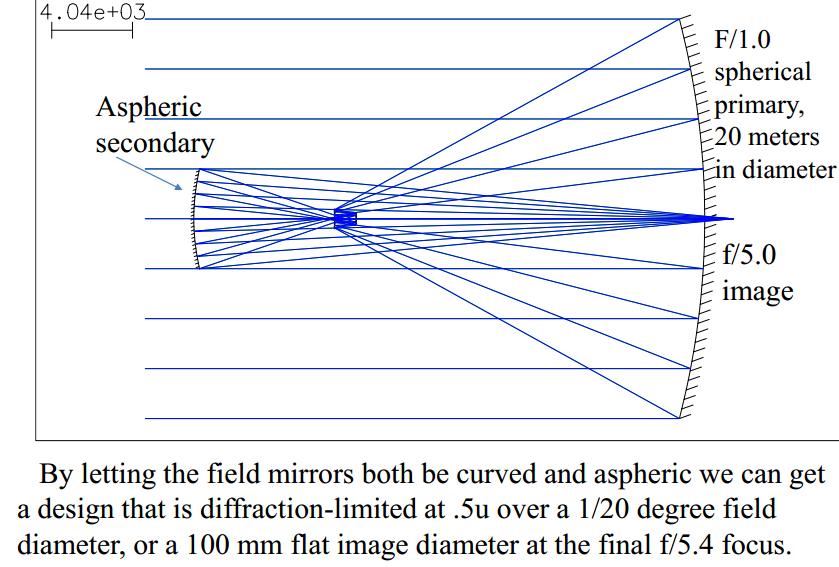
49 f/.75 primary mirror Recently I have discovered an amazing design, of just two conic surfaces with three reflections between them. With a 100 meter diameter f/.75 primary mirror and a f/4.6 system it is diffraction-limited at.5000u over a.10 degree diameter curved field, giving a 800 mm diameter image. Both mirrors are very close to being parabolas. The obscuration due to the hole in the secondary mirror is about 8% area. The big weakness is it can t be baffled well. If the primary is slowed down to f/1.0 then the design can be scaled up by 10X to give a kilometer-scope, with a kilometer diameter f/1.0 primary and diffraction-limited correction over a 4 meter diameter curved image. Yikes!!
50 f/1.0 primary mirror diffraction-limited f/6 system over a 4 meter diameter image One kilometer The Kilometer-Scope!!

51 Now we will use several design principles and tricks together to show how a Double- Gauss type of lens could have been designed before there were any computers. One of my general design principles that I always use is to try to separate and de-couple as much as possible different design tasks so that they can be done sequentially and not simultaneously. Before computers that approach would be very important, as a way to reduce the computational burden. These days it is a way to aid in understanding and gives better control of the design process. As one example, I always do a monochromatic design before even looking at color correction. We want to avoid piling up too many tasks that need to be done at the same time.

52 Designing a Double-Gauss lens, the Hard Way David Shafer David Shafer Optical Design Fairfield, CT, shaferlens@sbcglobal.net #

53 The Double-Gauss type of design is very flexible and can give good performance in a wide variety of combinations of field angle and f# speed. These days you can start a new design from a gazillion Double-Gauss design patents or just enter some design data that give a drawing that looks like a Double-Gauss and then computer optimize.

54 Back in the days before computers a very different style of lens design was necessary. People had to use some aberration theory and insights and did not do more than 2X 2 matrix optimization by hand. Let us see what that may have been like, but use a computer to do the required simple calculations, as if we were doing it by hand calculations. We will first do a monochromatic design and then add color correction.
55 Let s start with a plano-convex lens, with front radius of 50 mm, 40 mm aperture and a glass like Schott SK16, with an index close to 1.62 and low dispersion. We will be doing just a 3 rd order aberration design to get our starting point for computer optimization or, in the old days, for some very tedious hand raytracing calculations. The aperture stop is on the front lens (for now). Since we will be correcting the 3 rd -order aberrations to zero, the field angle and f# speed then don t enter in and have no effect. So we pick something that makes the lens drawings look good. After we get our 3 rd - order solution we can then choose the field angle and f# of interest, for ray optimizing.


56 To correct the coma of a single lens with aperture stop in contact, let us look a little more closely at it. Coma of a lens with the stop in contact varies linearly with the bending of the lens. For a thin lens (zero thickness) with the stop in contact the index of refraction that makes 3 rd order coma zero for a plano-convex lens is And this number is the famous Golden Mean or Golden Ratio from classical times. A simple algebraic equation links together lens bending, index and coma so it is easy to handle, pre-computer. The Golden Mean occurs constantly in nature and in art and architecture. And also in optics
57 The astigmatism field curves for this single lens with stop in contact look like this. Another case where the Golden Mean occurs in optics is the concentric spherical mirrors design, where for collimated input the radii ratio of the two mirrors that corrects for 3 rd order spherical aberration is There are other examples in optics.
58 The front lens has spherical aberration, coma, astigmatism and Petzval curvature. With the aperture stop at the front lens and a refractive index of about 1.62 (SK16 glass) the lens bending that makes coma go to zero is almost exactly the plano-convex case shown here. Then we add a thick lens that is concentric about the image for its front face and flat for its back face, right against the image. It is also SK16 glass. We know that a surface concentric about the image has no spherical aberration or coma but it does have astigmatism and Petzval. Its astigmatism is opposite in sign to that of the front lens. So we do a few trials and find that the second lens s front radius should be about 33 mm to cancel the astigmatism of the first lens. So now this two lens system is corrected for coma and astigmatism but still has spherical aberration (from the first lens) and Petzval curvature. The second lens is 33 mm thick, up to the image. The formula for 3 rd -order astigmatism of a surface curved concentric about the image is very simple and easy to handle in pre-computer days.
59 Field curves with astigmatism corrected Astigmatism corrected Petzval corrected The Petzval curvature of the image could now be corrected by moving the flat lens surface in contact with the image away from the image and putting a strong concave curve on that surface. A radius of 20 mm there would correct the Petzval of the design to zero. But that strong surface, no longer right at the image, would also add in a large amount of astigmatism, some coma, and give TIR for larger field angles. We will not do that.
60 Next we add a meniscus lens right after the first lens. Both of its surfaces are aplanatic about the axial ray, coming from the first lens. An aplanatic surface has no spherical aberration, coma, or astigmatism, but does have Petzval curvature. Since both surfaces are aplanatic it has no net affect on the axial ray angle the first aplanatic surface speeds up the axial ray cone angle and the second aplanatic surface slows it down by the same amount. The purpose of this meniscus lens is to largely correct the design for Petzval curvature. Its negative power is just what is needed to get a flat image and it does this without any spherical aberration, coma, or astigmatism of its own. The first and third lenses here have a combined Petzval radius of 52 mm. After adding the aplanatic second lens that becomes 100 mm.
61 The thickness of that second lens, with its two aplanatic surfaces, can be chosen to have different values providing different amounts of Petzval correction. But if its thickness is made to go all the way up to the front of the back lens it s still not enough Petzval correction to correct Petzval to zero. Here in the picture the Petzval image curvature is 150 mm radius the best that you can do. The surface next to the image could be curved to do some Petzval correction but that is not the plan here. A new lens is added that has both of its surfaces concentric about the chief ray. The chief ray angle is changed by the back surface of the second lens. The new lens with both surfaces concentric about that chief ray has no coma or astigmatism but does have spherical aberration and Petzval curvature. By doing some trials with the thicknesses of the second and third lenses we get the design shown, which has zero Petzval. Now we are left with only spherical aberration to be corrected (and then color next)
62 Petzval = 0 Petzval radius = 4X focal length Experienced designers, precomputer, knew that correcting Petzval to zero gives too much higher-order Petzval and astigmatism. So they usually corrected the Petzval radius to be 3 or 4X the system focal length. We do that here too. 3 rd order Petzval = 0 Petzval radius = 4X focal length
63 The third lens does not have enough spherical aberration to correct that of the front lens, But we can move that third lens to the left some, while keeping it concentric about the chief ray. That makes for a stronger front surface and more spherical aberration. Let s keep the thickness of that lens unchanged as we move it. Let us recap where we are now. The front lens, with the aperture stop there, has a bending shape that is corrected for coma. It has spherical aberration, astigmatism and Petzval curvature. The last lens here corrects for astigmatism without adding any spherical aberration or coma, because of its front surface concentric about the image. The second and third lens are double aplanatic, about the axial ray, and double concentric, about the chief ray. So they do not add any coma or astigmatism, but this pair of lenses does correct the system for Petzval, not to zero but to 4X the focal length. The next step is to correct for spherical aberration. The spherical aberration of the front positive lens and of the negative third lens concentric about the chief ray, are of opposite signs.
64 After we get the third lens to correct the spherical aberration of the first lens we move the last lens, which is unchanged, to stay concentric about the image. With this new design the Petzval correction has been changed a little, since the third lens has changed. We move the third lens to the left, keeping it concentric about the chief ray, until we get enough spherical aberration to correct for the spherical aberration of the first lens. The first and second lens do not change at all and we keep the thickness of the third lens unchanged as we move it to the left. The formula for 3 rd order spherical aberration of the two surfaces of the third lens, and of the first lens, are manageable and we are doing this design exercise here without tracing a single real ray.
65 The next step is to move the last lens surface away from its contact with the image. As we do that the rest of the design is not touched. The last surface is made concentric about the paraxial chief ray (which is nearly telecentric) so that last surface then has no coma or astigmatism. This is shown next. To restore the Petzval correction to what we want we reduce the thickness of the aplanatic/aplanatic second lens by a small amount just ½ mm and resolve for the concentric third lens that corrects for spherical aberration. The result is a monochromatic design, shown here, with corrected spherical aberration, coma, astigmatism and optimized Petzval. There are a lot of hand calculations required and that was the life of designers, before computers. But here we have reduced the amount of work by using aplanatic surfaces and surfaces concentric about the image or the chief ray.
66 The last lens surface has a very weak radius, concentric about the paraxial chief ray. It has no 3 rd order coma or astigmatism and the very small amount of 3 rd order spherical aberration it has is not worth changing the third lens for in order to correct it. Now we will do color correction. What we want is to be able to do that without disturbing at all the design that we have achieved so far, after a lot of hand calculations. The key to being able to do that is the way the glass type choices are handled.
67 Glass order = SK16, SK16, F2, F2, SK16 Now we do color correction. We made the glass type used so far be Schott SK16. There is a reason for that. This crown glass has almost exactly the same index of refraction as the flint glass Schott F2, which is much more dispersive. That means that we can now add a buried surface or two inside the lenses and use the F2 glass to correct for axial and lateral color. The buried surface will have essentially no index difference across it for the central wavelength and therefore will not upset the aplanatic and concentric conditions for the other surfaces. In most Double-Gauss designs there are two cemented doublets for the two meniscus lenses because it takes two separated flint lenses to correct for both axial and lateral color. In this design here only one flint lens is needed because of the almost telephoto first-order optics and both axial and lateral color can be corrected by a single flint lens in the right position. But here we have also made the third lens be F2 glass in order to reduce the power needed of the color correcting buried surface in the cemented doublet.
68 Glass order = SK16, SK16, F2, F2, SK16 In the old days experienced designers would know that you don t want to correct the paraxial axial color to zero because it has to be balanced off against chromatic variation of spherical aberration. Here we made the paraxial axial color be nearly zero. The beauty of this design approach for color correction is that we can change the radius of the buried surface in the cemented double of SK16 and F2 glass without having any effect on the rest of the design, since those two glasses have almost exactly the same index at the central wavelength. So far this has been a paraxial and 3 rd order design and so the field angle and f# have been irrelevant up until now. If 3 rd order spherical aberration = 0 then it is 0 for any f# value. Now let us scale our design to a focal length of 50 mm and evaluate it for a speed of f/2.5 and a full field angle of 20 degrees. That is shown next.
69 50 mm focal length, f/2.5, 20 degree full field By tracing a single axial real ray and then working with only the concentric lens some trials would allow the 3 rd and higher order spherical aberration to be balanced against each other. By working with just the buried surface radius and just one additional real ray axial color could be balanced against spherochromatism. Playing with just the aplanatic/aplanatic lens would allow 3 rd -order Petzval to be balanced against higher-order field curvature, using Coddington equations. Now let s us see what we have produced here. Not a single ray was traced. Only paraxial and 3 rd order aberrations were considered. No aberration balancing was done of lower order against higher order. No attempt has been made to find the aperture stop position that gives the best higher-order aberration. Axial color has not been balanced against spherochromatism. But in the old days, pre-computer, this would be a good starting point for hand tracing a few real rays and trying to do some of the aberration balancing that is needed. With just two or three rays and doing some one or two variable optimizations much could be done, back then.
70 On-axis 50 mm focal length, f/2.5, 20 degrees full field This is the ray trace results of our design, with no aberration balancing or any real rays traced during the design evolution Edge of field Remember, none of these ray traces would be seen at all during the design evolution. We did not trace any real rays
71 f/2.5, 20 degree full field Computer optimized design We will not do here the further optimization that would be done next, just described, using just 2 or 3 real rays and the Coddington equations, while doing simple 1X1 or 2X2 matrix calculations to calculate changes needed in the design. But that is what they did pre-computer. We will now jump right into modern computer optimization of the design, with very many real rays at several wavelenghs and vary all the radii and thicknesses and airspaces with no constraints on them, such as the aplanatic/aplanatic and concentric surfaces used here. Here are the results, with 2X smaller scale. The stop position was shifted was best results. There is no vignetting. On-axis Edge of field
72 Our local minimum solution The Double-Gauss form has many local minima and this design is stuck in a very short version of the normal Double-Gauss design. Much better performance will result if the design is coaxed or forced out of this minimum, mostly by having a shorter central airspace and a longer back focus due to a stronger back meniscus lens. Then the central airspace is nearly collimated like in this design. Then two flint glass lenses are needed to correct both axial and lateral color. By having crown and flint glasses have different index values, instead of the same that I used (SK16 and F2), extra aberration control is gained by the buried surfaces

73 So, in summary, a design technique is described here that would have been used, in whole or in part, in the old days before computer aided design. The pre-computer calculations were so tedious and time consuming that any idea that would reduce it was quickly adopted. The use of surfaces that were aplanatic or concentric about the image or chief ray would save effort because of their aberration behavior as demonstrated here. It also allowed parts of the design to be worked on while not disturbing the correction of other parts like the use of no index of refraction break across a buried surface. Or here, where an aplanatic/aplanatic lens can be changed to affect the Petzval curvature without changing the spherical aberration, coma, or astigmatism. These techniques allowed for some simple one or two variables hand optimization. Of course nobody in their right mind would do things this way today, when immense computer power can be brought to bear on the design process. But it is instructive to see how people in the old days were forced by necessity to think and to understand aberration theory in order to make the design process manageable. Now, we don t have to do that. Something has been gained and something has been lost.
74 Use of temporary aspherics in the Design Process This means using aspheric surfaces during the design s evolution but then removing them all before the final design. Aspherics can allow a design to move into a new solution region that is difficult to find without the aspherics. Aspherics can easily correct aberrations that may take several extra lenses to do without the aspherics. But once the design is in the new solution region it may no longer need the aspherics.

75 Suppose that you have a design and the performance is not as good as you would like. You would like to add a lens or two to get more design variables and improve the performance but you don t know where to do it to get the best effect. A good solution to this is to use the designer trick of temporary use of aspherics in the design. Here is what we do. First we make 3 or 4 of the lens surfaces aspheric and add low-order asphericity to the design variables. We choose locations for the aspherics to be at both ends of the design as well as one or two in the middle area. Then we reoptimize the design.

76 Usually only one of the aspheric locations chosen will have much effect and the others will have little effect. Here, with 4 aspherics spread throughout the design, we got a big improvement in the image quality. If we had not, then this first-order configuration is near the limit of what it can do and a different design type must be used. But here the design got very much better. Now we have to find out which one of the aspherics is the important one. Aspherics

77 We take our very good improved design and one by one try to remove the aspherics and reoptimize. We find that the two aspherics on either end of the design can be removed with almost no change in the reoptimized design. Of the two aspherics in the middle we find that only this one is important. With that one we get almost all the performance improvement that 4 aspherics gave.
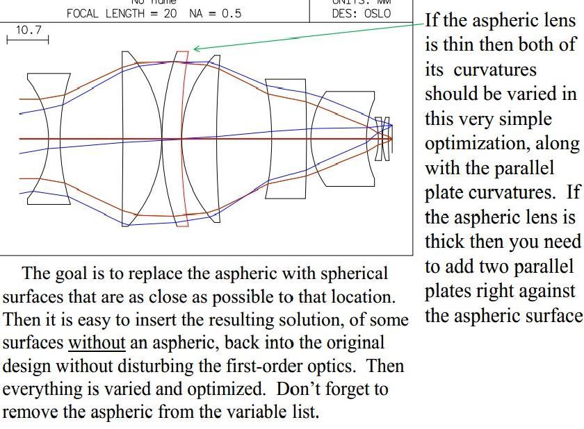
78 Now we will try to replace the one aspheric surface with a spherical surfaces doublet lens that has the same aberrations. There are several possibilities and some will have better higher-order aberrations than other ones. Next I will show how to find a doublet replacement for an aspheric surface Possible spherical surfaces doublet replacements for the aspheric

79 So a long process just shown resulted with a design with much better performance with an extra lens. We have shown here a systematic way of finding out where to add a lens to get the best performance improvement Some design programs have automated this and try different places to add a lens to a design. Doublet lens with no aspheric that replaces the aspheric single lens that was here.
80 Removing an aspheric from a design

81 Still with me?
82 20 degree field diameter, f/1.0,.015 waves r.m.s. OPD at edge of field, with a strong aspheric
83 Adding a lens or lenses near the aspheric surface gives more design variables in that location within the design and then can allow the aspheric to be removed.

84 A small change in the position of the aspheric within the design can make a very considerable difference in how hard it is to remove it
85 We will replace the aspheric surface with a doublet lens in the same location and with the same aberrations. That is done by changing only the region right next to the aspheric surface, while freezing the rest of the design. Once an equivalent doublet has been found, that is substituted for the aspheric and then the rest of the design is un-frozen and everything is varied and reoptimized.

86 The multiple solutions will include positive/negative doublets, negative/positive doublets, some with a strong meniscus lens, and some with two positive lenses. Different starting points can lead to different solutions. You want what gives the best 3 rd and 5 th order equivalent to the aspheric being replaced.
87
88
89 A different design example. An aspheric in the middle of the design is replaced by a doublet and there are two similar solutions found for the aspheric replacement
90 Brixner Parallel Plate Design Method This design method starts with all or mostly parallel plates and computer optimizes to specs set by designer, like focal length, back focal length, distortion, etc. Results are highly dependent on initial conditions. No human direction required.
91 Airspaces here are a little different in starting point
92 Stop position was not varied Best design of these three examples, where only change in starting system is airspaces of parallel plates
Lens Design I. Lecture 10: Optimization II Herbert Gross. Summer term
 Lens Design I Lecture : Optimization II 5-6- Herbert Gross Summer term 5 www.iap.uni-jena.de Preliminary Schedule 3.. Basics.. Properties of optical systrems I 3 7.5..5. Properties of optical systrems
Lens Design I. Lecture 10: Optimization II Herbert Gross. Summer term
 Lens Design I Lecture : Optimization II 8-6- Herbert Gross Summer term 8 www.iap.uni-jena.de Preliminary Schedule - Lens Design I 8.4. Basics 9.4. Properties of optical systems I 3 6.4. Properties of optical
Optical Design with Zemax for PhD
 Optical Design with Zemax for PhD Lecture 7: Optimization II 26--2 Herbert Gross Winter term 25 www.iap.uni-jena.de 2 Preliminary Schedule No Date Subject Detailed content.. Introduction 2 2.2. Basic Zemax
Lens Design I. Lecture 3: Properties of optical systems II Herbert Gross. Summer term
 Lens Design I Lecture 3: Properties of optical systems II 207-04-20 Herbert Gross Summer term 207 www.iap.uni-jena.de 2 Preliminary Schedule - Lens Design I 207 06.04. Basics 2 3.04. Properties of optical
Lens Design II. Lecture 2: Structural modifications Herbert Gross. Winter term
 Lens Design II Lecture 2: Structural modifications 26--26 Herbert Gross Winter term 26 www.iap.uni-jena.de 2 Preliminary Schedule 9.. Aberrations and optimization Repetition 2 26.. Structural modifications
Lens Design I. Lecture 3: Properties of optical systems II Herbert Gross. Summer term
 Lens Design I Lecture 3: Properties of optical systems II 205-04-8 Herbert Gross Summer term 206 www.iap.uni-jena.de 2 Preliminary Schedule 04.04. Basics 2.04. Properties of optical systrems I 3 8.04.
Waves & Oscillations
 Physics 42200 Waves & Oscillations Lecture 33 Geometric Optics Spring 2013 Semester Matthew Jones Aberrations We have continued to make approximations: Paraxial rays Spherical lenses Index of refraction
Introduction to Optical Modeling. Friedrich-Schiller-University Jena Institute of Applied Physics. Lecturer: Prof. U.D. Zeitner
 Introduction to Optical Modeling Friedrich-Schiller-University Jena Institute of Applied Physics Lecturer: Prof. U.D. Zeitner The Nature of Light Fundamental Question: What is Light? Newton Huygens / Maxwell
OPTICAL IMAGING AND ABERRATIONS
 OPTICAL IMAGING AND ABERRATIONS PARTI RAY GEOMETRICAL OPTICS VIRENDRA N. MAHAJAN THE AEROSPACE CORPORATION AND THE UNIVERSITY OF SOUTHERN CALIFORNIA SPIE O P T I C A L E N G I N E E R I N G P R E S S A
Sequential Ray Tracing. Lecture 2
 Sequential Ray Tracing Lecture 2 Sequential Ray Tracing Rays are traced through a pre-defined sequence of surfaces while travelling from the object surface to the image surface. Rays hit each surface once
Optical Design with Zemax
 Optical Design with Zemax Lecture : Correction II 3--9 Herbert Gross Summer term www.iap.uni-jena.de Correction II Preliminary time schedule 6.. Introduction Introduction, Zemax interface, menues, file
Applied Optics. , Physics Department (Room #36-401) , ,
 , ,") Applied Optics Professor, Physics Department (Room #36-401) 2290-0923, 019-539-0923, shsong@hanyang.ac.kr Office Hours Mondays 15:00-16:30, Wednesdays 15:00-16:30 TA (Ph.D. student, Room #36-415) 2290-0921,
Applied Optics Professor, Physics Department (Room #36-401) 2290-0923, 019-539-0923, shsong@hanyang.ac.kr Office Hours Mondays 15:00-16:30, Wednesdays 15:00-16:30 TA (Ph.D. student, Room #36-415) 2290-0921,
Lens Design II. Lecture 11: Further topics Herbert Gross. Winter term
 Lens Design II Lecture : Further topics 28--8 Herbert Gross Winter term 27 www.iap.uni-ena.de 2 Preliminary Schedule Lens Design II 27 6.. Aberrations and optimization Repetition 2 23.. Structural modifications
Tutorial Zemax 8: Correction II
 Tutorial Zemax 8: Correction II 2012-10-11 8 Correction II 1 8.1 High-NA Collimator... 1 8.2 Zoom-System... 6 8.3 New Achromate and wide field system... 11 8 Correction II 8.1 High-NA Collimator An achromatic
Advanced Lens Design
 Advanced Lens Design Lecture 4: Optimization III 2013-11-04 Herbert Gross Winter term 2013 www.iap.uni-jena.de 2 Preliminary Schedule 1 15.10. Introduction Paraxial optics, ideal lenses, optical systems,
Introductions to aberrations OPTI 517
 Introductions to aberrations OPTI 517 Lecture 11 Spherical aberration Meridional and sagittal ray fans Spherical aberration 0.25 wave f/10; f=100 mm; wave=0.0005 mm Spherical aberration 0.5 wave f/10;
Exam Preparation Guide Geometrical optics (TN3313)
") Exam Preparation Guide Geometrical optics (TN3313) Lectures: September - December 2001 Version of 21.12.2001 When preparing for the exam, check on Blackboard for a possible newer version of this guide.
Exam Preparation Guide Geometrical optics (TN3313) Lectures: September - December 2001 Version of 21.12.2001 When preparing for the exam, check on Blackboard for a possible newer version of this guide.
Lecture 2: Geometrical Optics. Geometrical Approximation. Lenses. Mirrors. Optical Systems. Images and Pupils. Aberrations.
 Lecture 2: Geometrical Optics Outline 1 Geometrical Approximation 2 Lenses 3 Mirrors 4 Optical Systems 5 Images and Pupils 6 Aberrations Christoph U. Keller, Leiden Observatory, keller@strw.leidenuniv.nl
 Telecentric Imaging Object space telecentricity stop source: edmund optics The 5 classical Seidel Aberrations First order aberrations Spherical Aberration (~r 4 ) Origin: different focal lengths for different
Performance Factors. Technical Assistance. Fundamental Optics
 Performance Factors After paraxial formulas have been used to select values for component focal length(s) and diameter(s), the final step is to select actual lenses. As in any engineering problem, this
Lecture 4: Geometrical Optics 2. Optical Systems. Images and Pupils. Rays. Wavefronts. Aberrations. Outline
 Lecture 4: Geometrical Optics 2 Outline 1 Optical Systems 2 Images and Pupils 3 Rays 4 Wavefronts 5 Aberrations Christoph U. Keller, Leiden University, keller@strw.leidenuniv.nl Lecture 4: Geometrical
OPAC 202 Optical Design and Inst.
 OPAC 202 Optical Design and Inst. Topic 9 Aberrations Department of http://www.gantep.edu.tr/~bingul/opac202 Optical & Acustical Engineering Gaziantep University Apr 2018 Sayfa 1 Introduction The influences
Area of the Secondary Mirror Obscuration Ratio = Area of the EP Ignoring the Obscuration
 Compact Gregorian Telescope Design a compact 10X25 Gregorian telescope. The Gregorian telescope provides an erect image and consists of two concave mirrors followed by an eyepiece to produce an afocal
Optimisation. Lecture 3
 Optimisation Lecture 3 Objectives: Lecture 3 At the end of this lecture you should: 1. Understand the use of Petzval curvature to balance lens components 2. Know how different aberrations depend on field
Exercise 1 - Lens bending
 Exercise 1 - Lens bending Most of the aberrations change with the bending of a lens. This is demonstrated in this exercise. a) Establish a lens with focal length f = 100 mm made of BK7 with thickness 5
Image Formation. Light from distant things. Geometrical optics. Pinhole camera. Chapter 36
 Light from distant things Chapter 36 We learn about a distant thing from the light it generates or redirects. The lenses in our eyes create images of objects our brains can process. This chapter concerns
Ch 24. Geometric Optics
 text concept Ch 24. Geometric Optics Fig. 24 3 A point source of light P and its image P, in a plane mirror. Angle of incidence =angle of reflection. text. Fig. 24 4 The blue dashed line through object
1.1 Singlet. Solution. a) Starting setup: The two radii and the image distance is chosen as variable.
 Starting setup: The two radii and the image distance is chosen as variable.") 1 1.1 Singlet Optimize a single lens with the data λ = 546.07 nm, object in the distance 100 mm from the lens on axis only, focal length f = 45 mm and numerical aperture NA = 0.07 in the object space.
1 1.1 Singlet Optimize a single lens with the data λ = 546.07 nm, object in the distance 100 mm from the lens on axis only, focal length f = 45 mm and numerical aperture NA = 0.07 in the object space.
Exam questions OPTI 517. Only a calculator and a single sheet of paper, 8 X11, with formulas will be allowed during the exam.
 Exam questions OPTI 517 Only a calculator an a single sheet of paper, 8 X11, with formulas will be allowe uring the exam. 1) A single optical spherical surface oes not contribute spherical aberration.
Lens Design II. Lecture 11: Further topics Herbert Gross. Winter term
 Lens Design II Lecture : Further topics 26--2 Herbert Gross Winter term 25 www.iap.uni-ena.de Preliminary Schedule 2 2.. Aberrations and optimization Repetition 2 27.. Structural modifications Zero operands,
GEOMETRICAL OPTICS AND OPTICAL DESIGN
 GEOMETRICAL OPTICS AND OPTICAL DESIGN Pantazis Mouroulis Associate Professor Center for Imaging Science Rochester Institute of Technology John Macdonald Senior Lecturer Physics Department University of
Introduction. Geometrical Optics. Milton Katz State University of New York. VfeWorld Scientific New Jersey London Sine Singapore Hong Kong
 Introduction to Geometrical Optics Milton Katz State University of New York VfeWorld Scientific «New Jersey London Sine Singapore Hong Kong TABLE OF CONTENTS PREFACE ACKNOWLEDGMENTS xiii xiv CHAPTER 1:
Advanced Lens Design
 Advanced Lens Design Lecture 3: Aberrations I 214-11-4 Herbert Gross Winter term 214 www.iap.uni-jena.de 2 Preliminary Schedule 1 21.1. Basics Paraxial optics, imaging, Zemax handling 2 28.1. Optical systems
Astronomy 80 B: Light. Lecture 9: curved mirrors, lenses, aberrations 29 April 2003 Jerry Nelson
 Astronomy 80 B: Light Lecture 9: curved mirrors, lenses, aberrations 29 April 2003 Jerry Nelson Sensitive Countries LLNL field trip 2003 April 29 80B-Light 2 Topics for Today Optical illusion Reflections
Lens Design I Seminar 1
 Xiang Lu, Ralf Hambach Friedrich Schiller University Jena Institute of Applied Physics Albert-Einstein-Str 15 07745 Jena Lens Design I Seminar 1 Warm-Up (20min) Setup a single, symmetric, biconvex lens
Big League Cryogenics and Vacuum The LHC at CERN
 Big League Cryogenics and Vacuum The LHC at CERN A typical astronomical instrument must maintain about one cubic meter at a pressure of
Optical Design with Zemax
 Optical Design with Zemax Lecture : Correction I 203-0-22 Herbert Gross Summer term 202 www.iap.uni-jena.de Preliminary time schedule 2 6.0. Introduction Introduction, Zemax interface, menues, file handling,
Lens Design II. Lecture 8: Special correction topics Herbert Gross. Winter term
 Lens Design II Lecture 8: Special correction topics 2018-12-12 Herbert Gross Winter term 2018 www.iap.uni-jena.de 2 Preliminary Schedule Lens Design II 2018 1 17.10. Aberrations and optimization Repetition
Laboratory experiment aberrations
 Laboratory experiment aberrations Obligatory laboratory experiment on course in Optical design, SK2330/SK3330, KTH. Date Name Pass Objective This laboratory experiment is intended to demonstrate the most
Lenses Design Basics. Introduction. RONAR-SMITH Laser Optics. Optics for Medical. System. Laser. Semiconductor Spectroscopy.
 Introduction Optics Application Lenses Design Basics a) Convex lenses Convex lenses are optical imaging components with positive focus length. After going through the convex lens, parallel beam of light
INTRODUCTION TO ABERRATIONS IN OPTICAL IMAGING SYSTEMS
 INTRODUCTION TO ABERRATIONS IN OPTICAL IMAGING SYSTEMS JOSE SASIÄN University of Arizona ШШ CAMBRIDGE Щ0 UNIVERSITY PRESS Contents Preface Acknowledgements Harold H. Hopkins Roland V. Shack Symbols 1 Introduction
SPIE. Lens Design Fundamentals PRESS. Second Edition RUDOLF KINGSLAKE R. BARRY JOHNSON
 Lens Design Fundamentals Second Edition RUDOLF KINGSLAKE R. BARRY JOHNSON AMSTERDAM BOSTON HEIDELBERG LONDON NEW YORK OXFORD PARIS SAN DIEGO SAN FRANCISCO SINGAPORE SYDNEY TOKYO Academic Press is an imprint
Computer exercise 2 geometrical optics and the telescope
 Computer exercise 2 geometrical optics and the telescope In this exercise, you will learn more of the tools included in Synopsys, including how to find system specifications such as focal length and F-number.
EE119 Introduction to Optical Engineering Spring 2002 Final Exam. Name:
 EE119 Introduction to Optical Engineering Spring 2002 Final Exam Name: SID: CLOSED BOOK. FOUR 8 1/2 X 11 SHEETS OF NOTES, AND SCIENTIFIC POCKET CALCULATOR PERMITTED. TIME ALLOTTED: 180 MINUTES Fundamental
Mirrors, Lenses &Imaging Systems
 Mirrors, Lenses &Imaging Systems We describe the path of light as straight-line rays And light rays from a very distant point arrive parallel 145 Phys 24.1 Mirrors Standing away from a plane mirror shows
Lens Design II. Lecture 8: Special correction features I Herbert Gross. Winter term
 Lens Design II Lecture 8: Special correction features I 2017-12-04 Herbert Gross Winter term 2017 www.iap.uni-jena.de 2 Preliminary Schedule Lens Design II 2017 1 16.10. Aberrations and optimization Repetition
Index. B Back focal length, 12 Beam expander, 35 Berek, Max, 244 Binary phase grating, 326 Buried surface, 131,
 About the Author The author studied Technical Physics at the Technical University of Delft, The Netherlands. He obtained a master s degree in 1965 with a thesis on the fabrication of lasers. After military
Lens Design II. Lecture 8: Special correction features I Herbert Gross. Winter term
 Lens Design II Lecture 8: Special correction features I 2015-12-08 Herbert Gross Winter term 2015 www.iap.uni-jena.de Preliminary Schedule 2 1 20.10. Aberrations and optimization Repetition 2 27.10. Structural
Phys 531 Lecture 9 30 September 2004 Ray Optics II. + 1 s i. = 1 f
 Phys 531 Lecture 9 30 September 2004 Ray Optics II Last time, developed idea of ray optics approximation to wave theory Introduced paraxial approximation: rays with θ 1 Will continue to use Started disussing
25 cm. 60 cm. 50 cm. 40 cm.
 Geometrical Optics 7. The image formed by a plane mirror is: (a) Real. (b) Virtual. (c) Erect and of equal size. (d) Laterally inverted. (e) B, c, and d. (f) A, b and c. 8. A real image is that: (a) Which
Lens Design I. Lecture 5: Advanced handling I Herbert Gross. Summer term
 Lens Design I Lecture 5: Advanced handling I 2018-05-17 Herbert Gross Summer term 2018 www.iap.uni-jena.de 2 Preliminary Schedule - Lens Design I 2018 1 12.04. Basics 2 19.04. Properties of optical systems
Magnification, stops, mirrors More geometric optics
 Magnification, stops, mirrors More geometric optics D. Craig 2005-02-25 Transverse magnification Refer to figure 5.22. By convention, distances above the optical axis are taken positive, those below, negative.
COURSE NAME: PHOTOGRAPHY AND AUDIO VISUAL PRODUCTION (VOCATIONAL) FOR UNDER GRADUATE (FIRST YEAR)
 FOR UNDER GRADUATE (FIRST YEAR)") COURSE NAME: PHOTOGRAPHY AND AUDIO VISUAL PRODUCTION (VOCATIONAL) FOR UNDER GRADUATE (FIRST YEAR) PAPER TITLE: BASIC PHOTOGRAPHIC UNIT - 3 : SIMPLE LENS TOPIC: LENS PROPERTIES AND DEFECTS OBJECTIVES By
COURSE NAME: PHOTOGRAPHY AND AUDIO VISUAL PRODUCTION (VOCATIONAL) FOR UNDER GRADUATE (FIRST YEAR) PAPER TITLE: BASIC PHOTOGRAPHIC UNIT - 3 : SIMPLE LENS TOPIC: LENS PROPERTIES AND DEFECTS OBJECTIVES By
CH. 23 Mirrors and Lenses HW# 6, 7, 9, 11, 13, 21, 25, 31, 33, 35
 CH. 23 Mirrors and Lenses HW# 6, 7, 9, 11, 13, 21, 25, 31, 33, 35 Mirrors Rays of light reflect off of mirrors, and where the reflected rays either intersect or appear to originate from, will be the location
Aberrations of a lens
 Aberrations of a lens 1. What are aberrations? A lens made of a uniform glass with spherical surfaces cannot form perfect images. Spherical aberration is a prominent image defect for a point source on
Optical Systems: Pinhole Camera Pinhole camera: simple hole in a box: Called Camera Obscura Aristotle discussed, Al-Hazen analyzed in Book of Optics
 Optical Systems: Pinhole Camera Pinhole camera: simple hole in a box: Called Camera Obscura Aristotle discussed, Al-Hazen analyzed in Book of Optics 1011CE Restricts rays: acts as a single lens: inverts
Geometric optics & aberrations
 Geometric optics & aberrations Department of Astrophysical Sciences University AST 542 http://www.northerneye.co.uk/ Outline Introduction: Optics in astronomy Basics of geometric optics Paraxial approximation
Optical System Design
 Phys 531 Lecture 12 14 October 2004 Optical System Design Last time: Surveyed examples of optical systems Today, discuss system design Lens design = course of its own (not taught by me!) Try to give some
Some of the important topics needed to be addressed in a successful lens design project (R.R. Shannon: The Art and Science of Optical Design)
") Lens design Some of the important topics needed to be addressed in a successful lens design project (R.R. Shannon: The Art and Science of Optical Design) Focal length (f) Field angle or field size F/number
Lens design Some of the important topics needed to be addressed in a successful lens design project (R.R. Shannon: The Art and Science of Optical Design) Focal length (f) Field angle or field size F/number
Study on Imaging Quality of Water Ball Lens
 2017 2nd International Conference on Mechatronics and Information Technology (ICMIT 2017) Study on Imaging Quality of Water Ball Lens Haiyan Yang1,a,*, Xiaopan Li 1,b, 1,c Hao Kong, 1,d Guangyang Xu and1,eyan
TOPICS Recap of PHYS110-1 lecture Physical Optics - 4 lectures EM spectrum and colour Light sources Interference and diffraction Polarization
 TOPICS Recap of PHYS110-1 lecture Physical Optics - 4 lectures EM spectrum and colour Light sources Interference and diffraction Polarization Lens Aberrations - 3 lectures Spherical aberrations Coma, astigmatism,
Long Wave Infrared Scan Lens Design And Distortion Correction
 Long Wave Infrared Scan Lens Design And Distortion Correction Item Type text; Electronic Thesis Authors McCarron, Andrew Publisher The University of Arizona. Rights Copyright is held by the author. Digital
PHYS 160 Astronomy. When analyzing light s behavior in a mirror or lens, it is helpful to use a technique called ray tracing.
 Optics Introduction In this lab, we will be exploring several properties of light including diffraction, reflection, geometric optics, and interference. There are two sections to this lab and they may
Lens Design I Seminar 5
 Y. Sekman, X. Lu, H. Gross Friedrich Schiller University Jena Institute of Applied Physics Albert-Einstein-Str 15 07745 Jena Lens Design I Seminar 5 Exercise 5-1: PSF scaling (Homework) To check the Airy
Optical Design with Zemax
 Optical Design with Zemax Lecture 9: Advanced handling 2014-06-13 Herbert Gross Sommer term 2014 www.iap.uni-jena.de 2 Preliminary Schedule 1 11.04. Introduction 2 25.04. Properties of optical systems
R.B.V.R.R. WOMEN S COLLEGE (AUTONOMOUS) Narayanaguda, Hyderabad.
 Narayanaguda, Hyderabad.") R.B.V.R.R. WOMEN S COLLEGE (AUTONOMOUS) Narayanaguda, Hyderabad. DEPARTMENT OF PHYSICS QUESTION BANK FOR SEMESTER III PAPER III OPTICS UNIT I: 1. MATRIX METHODS IN PARAXIAL OPTICS 2. ABERATIONS UNIT II
R.B.V.R.R. WOMEN S COLLEGE (AUTONOMOUS) Narayanaguda, Hyderabad. DEPARTMENT OF PHYSICS QUESTION BANK FOR SEMESTER III PAPER III OPTICS UNIT I: 1. MATRIX METHODS IN PARAXIAL OPTICS 2. ABERATIONS UNIT II
INDEX OF REFRACTION index of refraction n = c/v material index of refraction n
 INDEX OF REFRACTION The index of refraction (n) of a material is the ratio of the speed of light in vacuuo (c) to the speed of light in the material (v). n = c/v Indices of refraction for any materials
Physics II. Chapter 23. Spring 2018
 Physics II Chapter 23 Spring 2018 IMPORTANT: Except for multiple-choice questions, you will receive no credit if you show only an answer, even if the answer is correct. Always show in the space on your
This experiment is under development and thus we appreciate any and all comments as we design an interesting and achievable set of goals.
 Experiment 7 Geometrical Optics You will be introduced to ray optics and image formation in this experiment. We will use the optical rail, lenses, and the camera body to quantify image formation and magnification;
PHY170: OPTICS. Things to do in the lab INTRODUCTORY REMARKS OPTICS SIMULATIONS
 INTRODUCTORY REMARKS PHY170: OPTICS The optics experiments consist of two major parts. Setting up various components and performing the experiments described below. Computer simulation of images generated
Warren J. Smith Chief Scientist, Consultant Rockwell Collins Optronics Carlsbad, California
 Modern Optical Engineering The Design of Optical Systems Warren J. Smith Chief Scientist, Consultant Rockwell Collins Optronics Carlsbad, California Fourth Edition Me Graw Hill New York Chicago San Francisco
Unit 5.B Geometric Optics
 Unit 5.B Geometric Optics Early Booklet E.C.: + 1 Unit 5.B Hwk. Pts.: / 18 Unit 5.B Lab Pts.: / 25 Late, Incomplete, No Work, No Units Fees? Y / N Essential Fundamentals of Geometric Optics 1. Convex surfaces
OSLO Doublet Optimization Tutorial
 OSLO Doublet Optimization Tutorial This tutorial helps optical designers with the most basic process for setting up a lens and optimizing in OSLO. The example intentionally goes through basics as well
Optical Zoom System Design for Compact Digital Camera Using Lens Modules
 Journal of the Korean Physical Society, Vol. 50, No. 5, May 2007, pp. 1243 1251 Optical Zoom System Design for Compact Digital Camera Using Lens Modules Sung-Chan Park, Yong-Joo Jo, Byoung-Taek You and
Why is There a Black Dot when Defocus = 1λ?
 Why is There a Black Dot when Defocus = 1λ? W = W 020 = a 020 ρ 2 When a 020 = 1λ Sag of the wavefront at full aperture (ρ = 1) = 1λ Sag of the wavefront at ρ = 0.707 = 0.5λ Area of the pupil from ρ =
ECEG105/ECEU646 Optics for Engineers Course Notes Part 4: Apertures, Aberrations Prof. Charles A. DiMarzio Northeastern University Fall 2008
 ECEG105/ECEU646 Optics for Engineers Course Notes Part 4: Apertures, Aberrations Prof. Charles A. DiMarzio Northeastern University Fall 2008 July 2003+ Chuck DiMarzio, Northeastern University 11270-04-1
University of Rochester Department of Physics and Astronomy Physics123, Spring Homework 5 - Solutions
 Problem 5. University of Rochester Department of Physics and Astronomy Physics23, Spring 202 Homework 5 - Solutions An optometrist finds that a farsighted person has a near point at 25 cm. a) If the eye
Chapter 18 Optical Elements
 Chapter 18 Optical Elements GOALS When you have mastered the content of this chapter, you will be able to achieve the following goals: Definitions Define each of the following terms and use it in an operational
Converging and Diverging Surfaces. Lenses. Converging Surface
 Lenses Sandy Skoglund 2 Converging and Diverging s AIR Converging If the surface is convex, it is a converging surface in the sense that the parallel rays bend toward each other after passing through the
Converging Lenses. Parallel rays are brought to a focus by a converging lens (one that is thicker in the center than it is at the edge).
.") Chapter 30: Lenses Types of Lenses Piece of glass or transparent material that bends parallel rays of light so they cross and form an image Two types: Converging Diverging Converging Lenses Parallel rays
Chapter 30: Lenses Types of Lenses Piece of glass or transparent material that bends parallel rays of light so they cross and form an image Two types: Converging Diverging Converging Lenses Parallel rays
Algebra Based Physics. Reflection. Slide 1 / 66 Slide 2 / 66. Slide 3 / 66. Slide 4 / 66. Slide 5 / 66. Slide 6 / 66.
 Slide 1 / 66 Slide 2 / 66 Algebra Based Physics Geometric Optics 2015-12-01 www.njctl.org Slide 3 / 66 Slide 4 / 66 Table of ontents lick on the topic to go to that section Reflection Refraction and Snell's
OPTICAL SYSTEMS OBJECTIVES
 101 L7 OPTICAL SYSTEMS OBJECTIVES Aims Your aim here should be to acquire a working knowledge of the basic components of optical systems and understand their purpose, function and limitations in terms
Geometrical Optics Optical systems
 Phys 322 Lecture 16 Chapter 5 Geometrical Optics Optical systems Magnifying glass Purpose: enlarge a nearby object by increasing its image size on retina Requirements: Image should not be inverted Image
ECEN 4606, UNDERGRADUATE OPTICS LAB
 ECEN 4606, UNDERGRADUATE OPTICS LAB Lab 2: Imaging 1 the Telescope Original Version: Prof. McLeod SUMMARY: In this lab you will become familiar with the use of one or more lenses to create images of distant
Average: Standard Deviation: Max: 99 Min: 40
 1 st Midterm Exam Average: 83.1 Standard Deviation: 12.0 Max: 99 Min: 40 Please contact me to fix an appointment, if you took less than 65. Chapter 33 Lenses and Op/cal Instruments Units of Chapter 33
Lens Design II Seminar 6 (Solutions)
") 2017-01-04 Prof. Herbert Gross Yi Zhong, Norman G. Worku Friedrich Schiller University Jena Institute of Applied Physics Albert-Einstein-Str 15 07745 Jena Lens Design II Seminar 6 (Solutions) 6.1. Correction
2017-01-04 Prof. Herbert Gross Yi Zhong, Norman G. Worku Friedrich Schiller University Jena Institute of Applied Physics Albert-Einstein-Str 15 07745 Jena Lens Design II Seminar 6 (Solutions) 6.1. Correction
Chapter 23. Light Geometric Optics
 Chapter 23. Light Geometric Optics There are 3 basic ways to gather light and focus it to make an image. Pinhole - Simple geometry Mirror - Reflection Lens - Refraction Pinhole Camera Image Formation (the
The Brownie Camera. Lens Design OPTI 517. Prof. Jose Sasian
 The Brownie Camera Lens Design OPTI 517 http://www.history.roch ester.edu/class/kodak/k odak.htm George Eastman (1854-1932), was an ingenious man who contributed greatly to the field of photography. He
Chapter 23. Mirrors and Lenses
 Chapter 23 Mirrors and Lenses Mirrors and Lenses The development of mirrors and lenses aided the progress of science. It led to the microscopes and telescopes. Allowed the study of objects from microbes
Name. Light Chapter Summary Cont d. Refraction
 Page 1 of 17 Physics Week 12(Sem. 2) Name Light Chapter Summary Cont d with a smaller index of refraction to a material with a larger index of refraction, the light refracts towards the normal line. Also,
CHAPTER 33 ABERRATION CURVES IN LENS DESIGN
 CHAPTER 33 ABERRATION CURVES IN LENS DESIGN Donald C. O Shea Georgia Institute of Technology Center for Optical Science and Engineering and School of Physics Atlanta, Georgia Michael E. Harrigan Eastman
PHYSICS FOR THE IB DIPLOMA CAMBRIDGE UNIVERSITY PRESS
 Option C Imaging C Introduction to imaging Learning objectives In this section we discuss the formation of images by lenses and mirrors. We will learn how to construct images graphically as well as algebraically.
Notation for Mirrors and Lenses. Chapter 23. Types of Images for Mirrors and Lenses. More About Images
 Notation for Mirrors and Lenses Chapter 23 Mirrors and Lenses Sections: 4, 6 Problems:, 8, 2, 25, 27, 32 The object distance is the distance from the object to the mirror or lens Denoted by p The image
Cardinal Points of an Optical System--and Other Basic Facts
 Cardinal Points of an Optical System--and Other Basic Facts The fundamental feature of any optical system is the aperture stop. Thus, the most fundamental optical system is the pinhole camera. The image
Chapter 3. Introduction to Zemax. 3.1 Introduction. 3.2 Zemax
 Chapter 3 Introduction to Zemax 3.1 Introduction Ray tracing is practical only for paraxial analysis. Computing aberrations and diffraction effects are time consuming. Optical Designers need some popular
Exercises Advanced Optical Design Part 5 Solutions
 2014-12-09 Manuel Tessmer M.Tessmer@uni-jena.dee Minyi Zhong minyi.zhong@uni-jena.de Herbert Gross herbert.gross@uni-jena.de Friedrich Schiller University Jena Institute of Applied Physics Albert-Einstein-Str.
Dr. Todd Satogata (ODU/Jefferson Lab) Monday, April
 Monday, April") University Physics 227N/232N Mirrors and Lenses Homework Optics 2 due Friday AM Quiz Friday Optional review session next Monday (Apr 28) Bring Homework Notebooks to Final for Grading Dr. Todd Satogata
University Physics 227N/232N Mirrors and Lenses Homework Optics 2 due Friday AM Quiz Friday Optional review session next Monday (Apr 28) Bring Homework Notebooks to Final for Grading Dr. Todd Satogata
Classical Optical Solutions
 Petzval Lens Enter Petzval, a Hungarian mathematician. To pursue a prize being offered for the development of a wide-field fast lens system he enlisted Hungarian army members seeing a distraction from
Tutorial Zemax 9: Physical optical modelling I
 Tutorial Zemax 9: Physical optical modelling I 2012-11-04 9 Physical optical modelling I 1 9.1 Gaussian Beams... 1 9.2 Physical Beam Propagation... 3 9.3 Polarization... 7 9.4 Polarization II... 11 9 Physical