Table of Contents Cover 1 Letter from Owner 3 Table of Contents 5 Introduction 6 Diamond Tooling 7 Changing Diamonds 8 Personal Safety 9 Diamond
|
|
|
- Piers O’Connor’
- 5 years ago
- Views:
Transcription

1 Version 14 Ser #: Date: 4/7/2016
2
3
4
5 Table of Contents Cover 1 Letter from Owner 3 Table of Contents 5 Introduction 6 Diamond Tooling 7 Changing Diamonds 8 Personal Safety 9 Diamond Tooling Quick Reference 10 Plastics & Water System Testing Stage Motor on Drum Frame without Drum Handle Assembly Basic Frame Step View Complete Drum Bottom Drum Assembly Level I Bottom Drum Assembly Level II Bottom Drum Assembly Level III Top Plate Assembly Drum Sheave Assembly Intermediate Sheave Assembly PTO Tensioner Assembly Top Belt Idler Assembly Top Tensioner Assembly Belt Tightener Main Belt Idler Main Belt Spindle Planetary Assembly PTO Assembly Flex Head Tooling Inverter Operator Control Panel Belt Paths 64 Technical Data 65 Troubleshooting CE Conformity 70 Warranty 71-72


6 Introduction The SASE PDG 8000 planetary diamond grinders are designed for wet or dry grinding of marble, terrazzo, granite and concrete. Their applications range from rough grinding through to a polished finish. It is extremely important all users be familiar with the contents of this manual before commencing operation of either machine. Failure to do so may result in damage to machinery or expose operator to unnecessary dangers. head as the machine passes over floor areas with different slopes or undulations. Set-Up Position the grinder in the working area. Make sure there are diamonds underneath the machine, and that the head locks are tight. IMPORTANT Planetary head and grinding heads are set to turn in opposite directions of each other.(as shown in this depiction) IMPORTANT Only staff that has received the necessary training, both practically and theoretically concerning their usage should operate the machinery. Mechanical Action of Moving Machine Parts Several parts of this machine are understood to be dangerous. The Grind Head has a rotation and a counter rotation, keep body parts clear of the moving grinder head. The handle is heavy. Failure to lock the handle in place can result in operator injury. During operation, the machine has a twisting force. If you lose control of the machine, it will walk away without you. The operator has to maintain control of the machine. The machine moving freely can damage finished floor sections, or wall sections. Not to mention anyone caught by the grind head could be seriously injured. Preventative Maintenance Preventing the hazard is the best case scenario. Preventative Maintenance (PM) is the responsibility of the operator. Check and clean air filter regularly(200 operating hours) Keep a Log Book for all service done. Be sure that adequate vacuum system is in use. Be aware of changes in operation, smell, noise, etc. while operating Report to management ANY safety concerns. Follow manufacturer recommendations for all motor maintenance. Storage The machine should always be stored in a cool, dry location. Moisture may upset fragile electrical components. Break-Down The machine can be divided into two main parts. 1. Chassis/Frame section This comprises the handle bars, body panels, Propane tank, Steel frame and wheels. 2. Drum/Head this comprises the motor, cover, grinding/satellite/ planetary heads and internal components When using the machine, each grinding head must always have the same diamond type and number of diamonds as the other heads. Each diamond must also be the same height as the next. The Rubber skirt must be adjusted so that a good seal is established, between the floor and the drum. When setting the height of the handle, the operator is the guide. The comfort of the operator during grinding is key. The handlebar should rest right at the operator s hip bone. When the machine is running, there will be a grinding force to one side that can be felt through the handlebars. Use the hip to resist this force instead of the arms. Control Panel The control panel consists of a number of buttons, giving 6 separate controls. E- Stop - Brings the rotation to an abrupt halt, only in case of emergency. Excessive use will increase motor wear. Also, must be released(gently twist clockwise) Potentiometer - FWD - REV - Stop - Controls the speed of rotation and counter rotation simultaneously. Range: Low 1 to High 10 Starts the rotation of the drum in the 'forward' direction. Will not work if inverter is in fault or if the E-Stop is pressed down. Starts the rotation of the drum in the 'reverse' direction. Will not work if inverter is in fault or if the E-Stop is pressed down. Brings the rotation to a gentle halt. The machine has been manufactured to allow movement between the chassis and head via the connection point. This movement is important during the grinding process as it creates a floating effect for the head. The floating gives the head a self leveling effect, negating the need to adjust the height of the Reset - Reset the inverter, in case of fault. (takes a few seconds)
.")


7 Determining Diamond Selection Diamond Background Diamond abrasives usually consist of 2 components: Diamond powder (also known as diamond crystals or grit). By changing the size of the diamond powder or grit, we can change how coarse or fine the scratches will be that are left behind from the grinding process. A binding agent (metal or resin). Diamond powder is mixed and suspended in either a metal or resin binding agent. When suspended in a metal bond matrix, the finished product is referred to as a Metal Bond or Sintered diamond segment. When suspended in a resin bond matrix, the finished product is referred to as a Resin Bond diamond segment or pad. General Diamond Principles Diamond Grit Size: Changing the size of the diamond grit to a smaller particle/ grit size will affect the performance of the diamond tool in the following ways: Create a finer scratch pattern. Increase the life of the diamond tool. Following is a guide for this procedure. Preparation Press the Stop button and engage the Emergency Stop button. As an extra precaution, you can unplug the power cord. Change 1. Set handle in upright position. 2. Pull back on handle to lift grinding head off the ground (Above Top). 3. Lay machine back on the ground 4. Put on gloves. 5. Remove grinding disc from flex plate. 6. Check to ensure that all discs are secure. 7. Once new diamonds have been attached, reverse procedure to lower machine to ground. As new diamonds may be a different height than the set being previously used, re-adjust skirt to ensure good seal is established with the floor. The opposite will occur when changing to a larger particle/grit size. The Binding Agent/Metal Bond or Resin Bond: Increasing hardness of bond will Increase life of diamond tool. Decrease production rate. Cause diamond tool to leave finer scratches in dry grinding applications (when compared to a softer bond diamond tool with the same diamond grit size). A hard bond matrix should be used on a soft floor and a soft bond matrix should be used on a hard floor. Grinding disc set-up: The set-up of diamond segments on the grinding heads of the machine will influence the performance of the machine, the productivity levels and also the finished floor quality. There are basically two types of diamond configurations that can be used when grinding: 1. Half set of diamonds when there are diamonds placed at three alternating positions on the diamond holder discs. ( See pictures on upper right). 2. Full set of diamonds when there are diamonds placed at each of the six positions on the diamond holder discs. (See pictures on middle right). Changing of Diamonds Different applications often require different selections of diamond tooling. There will be many occasions when the grinding discs need to be changed. HALF-SET OF DIAMONDS FULL-SET OF DIAMONDS When the diamonds are set-up as a half-set, they tend to follow the surface of the floor. The half-set diamond configuration should only be used when an extremely flat floor finish is not required. Diamonds that are set-up as a full-set tend to not follow the surface of the floor. If the floor is wavy the machine will grind the high areas yet miss the low spots. The full-set diamond configuration should be used when a very flat floor finish is desired.. Personal Safety
8 Please read the operator s manual carefully and make sure you understand the instructions before using the machine. Reminder Always check electrical source before starting. WARNING! Dust forms when grinding which can cause injuries if inhaled. Use an approved breathing mask. Always provide for good ventilation while machine is in use. Always wear approved: Only qualified personnel should be allowed to operate machinery. Never use a machine that is faulty. Carry out the checks, maintenance and service instructions described in this manual. All repairs not covered in this manual must be performed by a repairer nominated by either the manufacturer or distributor. Always wear personal safety equipment such as sturdy non-slip boots, ear protection, dust mask and approved eye protection. Protective helmet Hearing protection Machinery should only be started when grinding heads are resting on the ground. The machine should not be started without the rubber dust skirt attached. It is essential a good seal between floor and machine be established for safety, especially when operating in dry grinding applications. Dust Mask Protective goggles When changing the grinding discs ensure the unit is OFF. Press the Stop button and when the machine is completely stopped, press the emergency stop button. Disconnect the power cord, to add protection. Non-slip boots with steel toe Protective gloves The machine should not be lifted by handles, motor, chassis or other parts. Transportation of the machine is best done on a pallet / skid to which the machine must be firmly secured. WARNING Under no circumstances may the machine be started without observing the safety instructions. At no time should lifting of machinery be attempted without mechanical means such as a hoist or a forklift. Should the user fail to comply with these, SASE Company Inc or its representatives are free from all liability both directly and indirectly. Read through these operating instructions and make sure that you understand the contents before starting to use the machine. Extreme caution must be used when moving machinery by hand on an inclined plane. Even the slightest slope can cause forces/ momentum making the machinery impossible to brake manually. Never use the machine if you are tired, if you have consumed any alcohol, or if you are taking medication that could affect your vision, your judgment or your coordination. Never use a machine that has been modified in any way from its original specification. Be on your guard for electrical shocks. Avoid having body contact with lightning conductors/metal in the ground. Should you, after reading these safety instructions, still feel uncertain about the safety risks involved you must not use the machine, please contact your SASE representative for more information.


9 Transportation The machine comes equipped with an electronic system called a variable speed drive or a frequency converter. The drive enables the variable speed and direction component of the motor. The drive is located in the steel cabinet mounted on the machine chassis. As with all electronic equipment, the drives are sensitive to excessive vibration, rough treatment and high levels of dust. Much care and attention has been given by SASE to ensure maximum protection is given to the drive. When transporting, it is important to ensure the machinery is properly secured at all times to eliminate bouncing. Ensure the chassis or frame section of the machine is secured down at all times when in transit. WARNING HIGH VOLTAGE! The machine should always be transported under cover limiting the exposed to natural elements in particular rain and snow. The machine should not be lifted by handle, motor, chassis or other parts. Transportation of the machine is best done on a pallet/skid to which the machine must be firmly secured. Do not attempt to slide the tines/forks from a fork lift under grinding heads unless on a pallet/skid. Failure to do so can cause extreme damage to grinding heads of machine and internal parts. IMPORTANT It is recommended that machinery be transported with a set of diamonds attached at all times to ensure protection of locking mechanism for diamond plates. Speed The grinding speed should start low and increase as the operator becomes more comfortable with the application. Be sure that the RPM s do not exceed 2000 when starting and stopping the drum rotation. The machine should be running and the drum rotating before speed selection is fine tuned. Inspection and/or maintenance should be carried out with the motor switched off and the plug disconnected. Safety Hazards Before using the equipment, inspect electrical lines, and connections. Make sure the machine is in good working order. Electrical shock from a split wire could be fatal. Check that the cord and extension cord are intact and in good condition. Never use the machine if the cord is damaged, hand it in to an authorized service workshop for repair. Do not use a rolled up extension cord. Electrical cords must not exceed 200ft in length. The machine should be connected to an earthed outlet socket. Check that the mains voltage corresponds with that stated on the rating plate on the machine. Ensure the cord is behind you when you start to use the machine so that the cord will not be damaged. This product is in accordance with applicable EU directives.
10
11


12 Number 19 attaches number 18 to number 17 here. Drill 2 holes into number 17 ~3mm bit 21 Number 15 and 16 attach number 6 / 7 to the frame here TOP VIEW SIDE VIEW Number 8 is inserted into the plastic half shells, creating threaded holes to attach numbers 9 and 10 PDG 8000 Plastics & Water System SCALE: 1:1 WEIGHT: SHEET 1 OF
13 Plastics & Water System Item No. Part No. Description Quantity 1 PDG NIPPLE, 1/4" X CLOSE GALV 2 2 PDG ELBOW, BRASS FEMALE 1/4 NPT X 1/4 NPT 2 3 PDG VALVE, 1/4 BALL 2 4 PDG FITTING, PUSH TO CONNECT 3/8 X 1/4 4 5 PDG TUBING, WATER 6 ft 6 PDG SHELL, RIGHT HAND 1 7 PDG SHELL, LEFT HAND 1 8 NB NUT, SLOTTED-BODY RIVET M6 4 9 PDG COVER, HALF SHELL 1 10 NB SCREW, FLANGED HEX HEAD CAP M6-1.0 X 30 ZINC 4 11 NB RING, EXTERNAL RETAINING 5/8' 18-8 SS SPIRAL 2 12 NB SPRING, EXTENTION X X PDG HOOK, SPRING 2 14 NB SCREW, FLANGED HEX HEAD CAP M X 16 NON-SERRATED ZINC 4 15 NB SCREW, FLANGED SOCKET HEAD CAP M X ZINC 2 16 NB WASHER, FLAT M8 X 20 X 4 ZINC 6 17 PDG TANK, WATER 1 18 PDG HOOK, RING 2 19 NB RIVET, BLIND 1/8 DIA L 4 20 PDG DECAL SET, PDG PDG TRIM, FLEXIBLE 3/16" X 5/8" 3 ft 22 PDG ADAPTER, USB CHARGER(NOT DISPLAYED)(Arrow 6 is nearly pointing where it goes) 1 Machines after serial number MMYY0350 incorporate "Roto-Molded" Plastic shells, previous versions used Fiber-Glass "Plastic" shells. If you are upgrading to Roto-Molded You will need every part on this page except #14 and only 1 #10 Machines after 05/20/2015 get USB charging docks; starting with serial number :

14 Back View PDG 8000 Testing Stage SCALE: 1:1 WEIGHT: SHEET 1 OF
15 Testing Stage Item No. Part No. Description Quantity 1 See Page 23 Frame with-out Drum Assembled 1 2 See Page 21 Motor On Drum Assembled 1 3 NB SCREW, HEX METAXENTRIC 1"-8 X 4" MODIFIED 2 4 PDG RACK, WEIGHT 1 5 PDG COVER, STEEL FRAME 1 6 NB SCREW, FLANGED HEX HEAD CAP M6-1.0 X 12 NON-SERRATED ZINCED 2 7 VAC.HS HOSE, BLACK PDG VACUUM 3.0" ID BY THE FOOT 6 ft 8 VAC CLAMP, 3" BLACK PDG VACUUM HOSE 2 9 VAC COUPLER, PLASTIC MALE FOR 3" VAC HOSE PART E 1 10 WVAC COUPLER, PLASTIC FEMALE FOR 3" VAC HOSE PART C 1 11 PDG WEIGHT, BALLAST 2

16 A DETAIL A SCALE 1 : 6 21 SCALE: 1:1 PDG 8000 Motor On Drum WEIGHT: SHEET 1 OF 1
17 Motor on Drum Item No. Part No. Description Quantity 1 PDG SHROUD, MOLDED VACUUM 1 2 PDG RUBBER, EPDM GASKET 8ft 3 NB SCREW, FLANGED HEX HEAD CAP M6-1.0 X PDG GASKET, MOTOR 2 5 PDG SPACER, MOTOR FOR COUPLING DESIGN PDG8K 1 6 HOL.U11899 MOTOR, V 15KW 50-60HZ SIEMENS(7/8/9 included) 1 7 HOL.U11970 Fan-Cover, MOTOR, V 15KW 50-60HZ SIEMENS(Part of 6) 0 8 HOL Fan-Blade, MOTOR, V 15KW 50-60HZ SIEMENS(Part of 6) 0 9 NB KEY, PARALLEL M5 X 20(Part of 6) 0 10 PDG COUPLER, CJ38/45 LOVEJOY 1 11 PDG BUSHING, SPYDER RED 1 12 NB SCREW, SOCKET HEAD M16-2 X 120 ZINC 4 13 PDG WHIP, MOTOR KIT 4 WIRE 8 AWG COMPLETE(PART OF INVERTER NOW) 0 14 PDG CABLE, GRIP 90(PART OF INVERTER NOW) 0 15 NB WASHER, 1-1/4" X 1" 2 16 NB /4 inch Toothed nut 1 17 NB LUG, TERMINAL 8 AWG #10 STUD(PART OF INVERTER NOW) 0 18 PDG SKIRT, RUBBER DUST 1 19 SEE PAGE 26 DRUM, COMPLETE 1 20 PDG PLATE, TOOLING MAGNETIC 3 21 NB SCREW, FLAT HEAD SOCKET CAP M X NB WASHER, LOCK M16 ZINC 4
18 PDG 8000 Frame without Drum SCALE: 1:1 WEIGHT: SHEET 1 OF
19 Frame W/O Drum Item No. Part No. Description Qty. 1 See Page 25 Handle Assembly 1 2 See Page 27 Basic Frame Assembly 1 3 PDG DRIVE, WITH ENCLOSURE E-SC SERIES 20HP V W/LEAD 1 4 NB SCREW, FLAT HEAD SOCKET CAP M6-1.0 X NB SCREW, HEX M6 X 180 STAINLESS 1 6 NB NUT, NYLOC M6 1 7 PDG CORD, GRIP (Not Shown) 1 8 SAS.CS8165 TWISTLOCK 50A 480V 3P MALE(Not Shown) 1 9 AIW.8X4.CORD CORD, POWER 8/4(Not Shown) 60ft 10 SAS.CS8164 TWISTLOCK 50A 480V 3P FEMALE(Not Shown) 1 11 PDG EYE, LIFTING M NB NUT, HEX M NYLOC 2 Low Voltage Option 3 PDG DRIVE, WITH ENCLOSURE E-SC SERIES 20HP 230V W/LEAD 1 8 SAS.CS8365 TWISTLOCK 50A 250V 3P FEM.(Not Shown) 1 9 AIW.6X4.CORD CORD, POWER 6/4(Not Shown) 60ft 10 SAS.CS8364 TWISTLOCK 50A 250V 3P MALE(Not Shown) 1 European Option 8 SAS.CS8365 TWISTLOCK 50A 250V 3P FEM.(Not Shown) 0 9 AIW.6X4.CORD CORD, POWER 6/4(Not Shown) 0 10 SAS.CS8364 TWISTLOCK 50A 250V 3P MALE(Not Shown) 0 Inverter Box, Fan Filters: Need to be washed or replaced every 100 operation hours. 13 PDG FILTER, INLET FINE ELECTRICAL BOX (Not shown) 2 14 PDG FILTER, OUTLET COARSE ELECTRICAL BOX (Not shown) 2 Machines with serial number from 384 to 456 intermittently, and 457 and above, should use these components. 2 parts. Components for the 2 part version can be found in previous manuals. Before this the frame was
20 TITLE: Handle Assembly SCALE: 1:6 WEIGHT: 18.6kg SHEET 1 OF
21 Handle Assembly Item No. Part No. Description Qty. 1 PDG STEM, HANDLE 1 2 NB WASHER, WAVEY 1 3 PDG ACTUATOR, STEM LOCK 1 4 PDG LOCK, HANDLE STEM 1 5 PDG COVER, HANDLE STEM 1 6 NB SCREW, SOCKET HEAD CAP M X ZINC 3 7 NB WASHER, FLAT M8 ZINC 1 8 NB KEY, PARALLEL M5 X PDG HANDLE, STEM LOCK LEVER 1 10 NB SCREW, BUTTON HEAD SOCKET CAP M X PDG CAP, HANDLE STEM 1 12 NB SCREW, SOCKET HEAD CAP M X ZINC 6 13 PDG PANEL, COMPLETE INTERFACE NO DISPLAY V NB SCREW, FLANGED SOCKET HEAD CAP M X 8 ZINC 4 15 PDG WRAP, 1/2" SPIRAL CORD (Not Shown) 2ft 16 PDG BAR, HANDLE 1 17 NB NUT, SHAFT KM8 M ZINC 1 18 PDG WRENCH, HANDLE BAR SPANNER 1 19 NB SCREW, BUTTON HEAD SOCKET M6 X NB Zip Tie Mount 1 21 PDG Vacuum Hose Hanger 1 22 NB M6x12 Socket Head Bolt Zip Tie (mounts to #20, fastens #13 wires) 1 24 PDG SPRING, COMPRESSION (located behind #4 inside handle) 1 25 NB WASHER, BELLEVILLE (located between #1 and #9 cone pointed to #9) 1 SETTING HANDLE POSITION: Using the provided spanner wrench, turn the nut counter-clockwise to remove completely. Place nut on opposite of handle stem, draw the handle taper out by turning the nut clockwise against the handle stem. To tighten the handle, put the nut on the original side of the handle and draw the taper back into the stem by turning the nut clockwise against the handle stem.
22 PDG 8000 Basic Frame SCALE: 1:9 WEIGHT:lb SHEET 1 OF
23 Basic Frame Item No. Part No. Description Qty. 1 PDG FRAME, SKELETAL 1 2 PDG BUSHING, METAXENTRIC 2 3 NB SCREW, MOD HEX HEAD CAP M24 X PDG BUSHING, WHEEL AXLE METRIC 4 5 PDG WHEEL, REAR M NB NUT, HEX M PDG PIVOT, HANDLE STEM 1 8 PDG SHIM, HANDLE STEM PIVOT 2 9 PDG RETAINER, VFM RIGHT 1 10 PDG RETAINER, VFM LEFT 1 11 NB SCREW, SOCKET HEAD CAP M6-1.0 X 8 ZINC NB SCREW, SOCKET HEAD CAP M X 35 4

24 PDG 8000 Step View SCALE: 1:20 WEIGHT: SHEET 1 OF
25 Step View Item No. Part No. Description Qty. 1 PDG STEP, TILT ASSIST 1 2 NB SCREW, SOCKET HEAD SHOULDER M12 X 16 ZINCED 2 3 PDG STUD, BALL GAS STRUT 4 4 PDG STRUT, GAS 2 5 PDG ROD,TILT STEP STOP V2 1 6 NB PIN, COTTER 0.093" WIRE 2 7 PDG TUBE, TILT STEP STOP (Covers # 5) 1
26 PDG 8000 Complete Drum SCALE: 1:11 WEIGHT: 191kg SHEET 1 OF
27 Complete Drum Item No. Part No. Description Qty. 1 See Page 37 Bottom Plate Assembled 1 2 PDG BELT, MAIN PK21 M75 X 3046 OC BOTTOM 1 3 PDG BELT, PTO PK6 M11 X 1310 OC MIDDLE 1 4 See Page 39 Top Plate Assembled 1 5 NB SCREW, SOCKET HEAD CAP M X ZINC 3 6 PDG BELT, TOP PK10 M35 X 1460 OC 1 7 PDG SHROUD, BOTTOM BELT DUST 1 8 NB SCREW, HEX M6-1.0 X PDG TAPE, PRESERVATION HEAT SHRINK 3" WHITE 24ft 10 PDG SHROUD, TOP BELT DUST 1 11 NB SCREW, SOCKET HEAD CAP M X ZINC b DG.1327 WASHER, LOCK INTERNAL TOOTH M8 ZINC PDG SEAL, FOAM/FELT 1 13 PDG ZIP TIE, 48" 2 14 NB SCREW, SOCKET FLAT HEAD CAP M X PDG PLATE, STATIONARY 1 16 PDG EAR, DRUM MOUNTING 2 17 PDG SEAL, AXLE NITRILE AL. SLURRY COVERS 3 18 PDG COVER, PLANETARY SLURRY ALUMINUM 3 19 NB SCREW, FLANGED HEX HEAD CAP M6-1.0 X 12 (Aluminum covers) 9 20 NB SCREW, FLANGED HEX HEAD CAP M6-1.0 X 12 (PTO cover) 3 21 PDG COVER, PTO SLURRY 1 22 PDG.8A FLEX HEAD, COMPLETE WITH REDSPRING 3 23 NB WASHER, LOCK M8 ZINC 9 24 NB SCREW, SOCKET HEAD CAP M X ZINC 9
28 PDG 8000 Bottom Drum Assembly Level I SCALE: 1:8 WEIGHT: 101.4kg SHEET 3 OF
29 Bottom Drum I Assembly Item No. Part No. Description Qty. 1 PDG PLATE, BOTTOM DRUM STEEL 1 2 PDG POST, MAIN TENSIONER REACT 1 3 PDG STANCION, INNER 3 4 PDG STANCION, PERIMETER 12 5 NB PIN, SPIRAL M3 X NB SCREW, SOCKET HEAD CAP M X ZINC 20
30 PDG 8000 Bottom Drum Assembly Level II SCALE: 1:8 WEIGHT: 101.4kg SHEET 2 OF
31 Bottom Drum II Assembly Item No. Part No. Description Qty. 1 See Page Bottom Drum I Assemnbled 1 2 PDG.8A SUBASSEM, BELT TIGHTENER 1 3 PDG.8A SUBASSEM, MAIN BELT IDLER 2 4 NB SET SCREW, M X PDG.8A SUBASSEM, MAIN BELT SPINDLE SPIDER REV NB SCREW, SOCKET HEAD CAP M X NB SCREW, SOCKET HEAD CAP M6-1.0 X 12 ZINC 6 8 NB SCREW, SOCKET HEAD CAP M6-1.0 X ZINC 12 #2 must be disassembled partially to install bottom belt.

32 DETAIL A SCALE 1 : 4 A 3 7 PDG 8000 Bottom Drum Assembly Level III SCALE: 1:8 WEIGHT: 101.4kg SHEET 1 OF
33 Bottom Drum III Assembly Item No. Part No. Description Qty. 1 PDG LINK, IDLER REINFORCING 1 2 PDG BAR, TENSIONER CONTROL 1 3 PDG ROD, MAIN BELT TENSIONER 1 4 NB NUT, TENSIONER M NB SCREW, SOCKET HEAD SHOULDER M12 X PDG.8A SUBASSEM, PTO 1 7 PDG.8A SUBASSEM, PLANETARY 3 8 PDG SPRING, TENSION MAIN BELT 1 9 NB SCREW, SOCKET HEAD CAP M X NB WASHER, FLAT M12 ZINC 2 11 NB NUT, JAM M NB SCREW, SOCKET HEAD CAP M X ZINC NB SCREW, SOCKET HEAD CAP M X ZINC 2 14 See Page Bottom Drum II Assembled 1
34 PDG 8000 Top Plate Assembly SCALE: 1:6 WEIGHT: 48.9kg SHEET 1 OF
35 Top Plate Assembly Item No. Part No. Description Qty. 1 PDG PLATE, TOP DRUM 1 2 PDG.2A SUBASSEM, PTO TENSIONER 1 3 PDG.8A SUBASSEM, TOP TENSIONER 1 4 PDG.8A SUBASSEM, TOP BELT IDLER 1 5 NB SCREW, SOCKET HEAD CAP M X ZINC 3 6 NB SCREW, SOCKET HEAD CAP M6-1.0 X 12 ZINC 8 7 NB SCREW, FLAT HEAD SOCKET CAP M X PDG.8A SUBASSEM, INTERMEDIATE SHEAVE 1 9 PDG.8A SUBASSEM, DRUM SHEAVE 1 For Drums built after 10/15/2015: The PTO tensioner clamp plate thickness has changed back to original, so, the bolts had to revert back as well.

36 PDG 8000 Drum Sheave SCALE: 1:10 WEIGHT: SHEET 1 OF
37 Drum Sheave Assembly Item No. Part No. Description Qty. 1 PDG SHEAVE, STATIONARY DRUM 1 2 PDG BEARING, RS 2 3 NB RING, INTERNAL RETAINING M PDG SPINDLE, DRUM 1 5 NB RING, EXTERNAL RETAINING M100 1 PDG.8A SUBASSEM, DRUM SHEAVE 1

38 PDG 8000 Intermediate Sheave SCALE: 1:10 WEIGHT: 6.11kg SHEET 1 OF
39 Intermediate Assembly Item No. Part No. Description Qty. 1 PDG AXLE, INTERMEDIATE 1 2 NB LUGNUT, M PDG SHEAVE, INTERMEDIATE 1 4 PDG HUB 1 5 PDG SPACER, PTO HUB 1 6 NB NUT, HEX FLANGE M PDG.8A SUBASSEM, INTERMEDIATE SHEAVE 1
40 PTO Tensioner Assembly SCALE: 1:2 WEIGHT: 1.99kg SHEET 1 OF TITLE:
41 PTO Tensioner Assembly Item No. Part No. Description Quantity 1 PDG PTO Tensioner Clamp 1 2 PDG PTO Tensioner Plate 1 3 PDG Bearing RS 1 4 PDG PTO Tension Idler 1 5 PDG PTO Tension Idler Spacer 1 6 PDG Modifed M20-2.5x55 Hex Head Screw* 1 7 NB M20x2.5 Jam Nut 1 PDG.2A PTO Tensioner Sub-Assembly x 1
42 4 Install O-Ring with dab of grease & prior to inserting bolt PDG 8000 Top Belt Idler Assembly SCALE: 1:2 WEIGHT: 1.1kg SHEET 1 OF
43 Top Idler Assembly Item No. Part No. Description Qty. 1 PDG BASE, TOP BELT IDLER 1 2 PDG IDLER, TOP BELT 1 3 PDG BEARING, RS 1 4 PDG O-RING, M PDG SCREW, MODIFIED SOCKET HEAD M X PDG.8A SUBASSEM, TOP BELT IDLER 1

44 Install O-Ring with dab of grease & prior to inserting bolt PDG 8000 Top Tensioner Assembly SCALE: 1:3 WEIGHT: 1.93kg SHEET 1 OF
45 Top Tensioner Assembly Item No. Part No. Description Qty. 1 PDG SPACER, TOP BELT TENSIONER IDLER 1 2 PDG IDLER, TOP BELT TENSIONER 1 3 PDG BEARING, RS 1 4 NB SCREW, FLAT HEAD SOCKET CAP M6-1.0 X PDG CLAMP, TOP BELT TENSIONER 1 6 PDG PLATE, BELT TENSIONER 1 7 PDG O-RING, M NB SCREW, LOW SOCKET HEAD CAP M X 50 1 PDG.8A SUBASSEM, TOP TENSIONER 1

46 PDG Main Belt Tightener SCALE: 1:5 WEIGHT: 5.89Kg SHEET 1 OF
47 Main Belt Tightener Assembly Item No. Part No. Description Qty. 1 PDG PIVOT, MAIN BELT TENSIONER 1 2 PDG ARM, LOWER TENSIONER 1 3 PDG STANCION, MAIN TENSIONER HEAVY 1 4 PDG SPACER, MAIN TENSIONER 1 5 PDG SPINDLE, MAIN TENSIONER 1 6 PDG SPACER, LOWER TENSIONER SPINDLE 1 7 PDG SPACER, UPPER TENSIONER SPINDLE 1 8 PDG BEARING, RS 2 9 PDG IDLER, MAIN TENSIONER 1 10 PDG ARM, UPPER TENSIONER 1 11 PDG GRUDGEON, TENSIONER 1 12 NB SCREW, FLAT HEAD SOCKET CAP TORX M6-1.0 X NB PIN, HARDENED M8 X NB SCREW, SOCKET HEAD CAP M X NB SCREW, FLAT HEAD SOCKET CAP M X PDG SPACER, LARGE PIVOT 1 17 PDG SPACER, SMALL PIVOT 1 18 NB WASHER, SPRING FINGER 1 PDG.8A SUBASSEM, BELT TIGHTENER 1 Machines after have a 2 hole pattern version of the lower arm (#2). Machines before use the 5 hole version.

48 PDG 8000 MAIN BELT IDLER SCALE: 1:4 WEIGHT: 2.27kg SHEET 1 OF
49 Main Idler Assembly Item No. Part No. Description Qty. 1 PDG SPINDLE, MAIN BELT IDLER 1 2 PDG IDLER, MAIN BELT 1 3 PDG BEARING, RS 2 4 PDG RETAINER, IDLER BEARING 1 5 NB PIN, HARDENED M8 X PDG SPACER, MAIN BELT IDLER BEARING 1 PDG.8A SUBASSEM, MAIN BELT IDLER 1

50 PDG 8000 Main Spindle SCALE: 1:3 WEIGHT: 6.14kg SHEET 1 OF
51 Main Spindle Assembly Item No. Part No. Description Qty. 1 PDG SHEAVE, MAIN DRIVE REV PDG BEARING, RS 2 3 PDG SPACER, OUTER MAIN BEARING 1 4 PDG SPACER, INNER MAIN BEARING 1 5 PDG SPINDLE, MAIN BEARING 1 6 NB RING, EXTERNAL RETAINING M NB PIN, CYLINDER M5 x PDG CAP, MAIN DRIVE COUPLER SHEAVE 1 9 NB SCREW, SOCKET HEAD CAP M5-0.8 X NB SET SCREW, M X 16 1 PDG.8A SUBASSEM, MAIN BELT SPINDLE SPIDER REV 3 1 Machines before serial number use an outdated revision of this part. To replace the Main Spindle on those machines, order 1 PDG.8A , as well as 1 PDG , 1 PDG , and 1 PDG

52 5 (1 : 2) TORQUE 80ft/lb2 TORQUE 60ft/lb2 X5 PRESS FIT RED LOCTITE (262 OR 263) SHOULD BE USED ON EACH FASTENER PDG 8000 Planetary Assembly SCALE: 1:5 WEIGHT: 5.14kg SHEET 1 OF
53 Planetary Assembly Item No. Part No. Description Qty. 1 PDG SHEAVE, PLANETARY 1 2 PDG AXLE, PLANETARY 40MM 1 3 NB PIN, HARDENED M8 X NB NUT, LUG M NB NUT, HEX FLANGE M PDG HUB 1 PDG.8A SUBASSEM, PLANETARY 1 Older versions of this assembly, use PDG without countersunk holes. That version uses NB (JAM NUTS), instead of NB (LUG NUTS)
 SCALE: 1:10 WEIGHT: 6.")
54 7 6 TORQUE 80ft/lb2 TORQUE 60ft/lb2 X5 PRESS FIT PDG 8000 POWER TAKE OFF (PTO) SCALE: 1:10 WEIGHT: 6.92 SHEET 1 OF
55 Power Take Off (PTO) Item No. Part No. Description Qty. 1 PDG HUB 1 2 PDG SHEAVE, PTO HUB 1 3 NB Lugnut, M PDG AXLE, PTO 1 5 NB NUT, HEX FLANGE M PDG SHEAVE, PTO DRIVE 1 7 NB SCREW, SOCKET HEAD CAP M6-1.0 X PDG.8A SUBASSEM, PTO 1
56 7 3X 9 7 4X 8 4X X PDG 8000 Flex Head SCALE: 1:5 WEIGHT: 3.81 SHEET 1 OF
57 Flex Head Item No. Part No. Description Qty. 1 PDG YOKE, SUSPENSION 4 2 PDG PLATE, DRIVING (Rev) 1 3 PDG PLATE, DRIVEN (QM) 1 4 PDG ELEMENT, CENTER STUDDED 1 5 PDG BUSHING, YOKE 4 6 PDG POST, SPRING 4 7 NB SCREW, FLAT HEAD SOCKET CAP M X NB SCREW, FLAT HEAD SOCKET CAP M X PDG LOCK, SHAMROCK PLATE ASSEM 1 10 PDG SPRING, DIE RED MEDIUM HARD 4 11 NB RING, EXTERNAL 1/2" 4 PDG.8A FLEX HEAD, COMPLETE WITH REDSPRING 1
58 Top View Bottom View 3 PDG 8000 Magnetic Tooling Plate SCALE: 1:5 WEIGHT: SHEET 1 OF
59 Tooling Plate Item No. Part No. Description Qty. 1 PDG PLATE, TOOLING HOL QCS METAL BOND ADAPTERS FOR MAGNETS 3 3 NB SCREW, FLAT HEAD SOCKET CAP M6-1.0 X 12 ZINC 9 4 PDG MAGNET, 5/8" OD X 1/8" THICK WITH CS HOLE NORTH 3 5 NB SCREW, M4 X 6 FLAT HEAD PHILLIPS S/S 3 PDG PLATE, MAGNETIC QCS DIAMOND CARRIER 3 Part #2, #4, and #5 can be sold, 1 each, as SAS : ADAPTER, QCS WITH MAGNET

60 Filter Maintenance: 100 Hours PDG 8000 Door Not Shown Control Box SCALE: 1:5 WEIGHT: 19.72kg SHEET 1 OF
61 Inverter Item No. Part No. Description Quantity 1 PDG Fan 2 2 PDG Holder, Fuse 3 3 PDG Fuse 3 4 PDG Low Volt Power Supply 1 4 PDG High Volt Power Supply 1 5 PDG Terminal, Connection DR1.5/4 1 6 PDG Terminal, Block M10/10P 1 7 PDG Terminal, M35/16P 1 8 PDG Drive Only, Mitsubishi Inverter/ 230V 1 8 PDG Drive Only, Mitsubishi Inverter/ 380V or 460V 1 9 PDG Filter, Fine Electrical Box 2 10 PDG Filter, Coarse Electrical Box 2 11 PDG Cable, 6 Pin Right Angle(Not on New Machines) 1 11 PDG Cable, 6 Pin Straight(Not on New Machines) 1 12 PDG Cable, 12 Pin Right Angle(Not on New Machines) 1 12 PDG Cable, 12 Pin Straight(Not on New Machines) 1 13 PDG Latch, Enclosure 2 14 PDG Filter Housing 4


62 PDG 8000 Operator Interface SCALE: 1:2 WEIGHT: 1.22kg SHEET 1 OF
63 Operator Control Panel Item No. Part No. Description Quantity 1 PDG Enclosure, Box 1 2 PDG Panel, No GOTT Face 1 3 PDG Pin Male Connector 1 4 PDG Emergency Stop 1 5 & 6 PDG Potentiometer, W/ Knob 1 7 PDG Green Push, Button 2 8 PDG Orange Push, Button 1 9 PDG Red Push, Button 1
64 B E L T T E N S I O N S 80 ±5 85 ±5 150 ±5

65
66
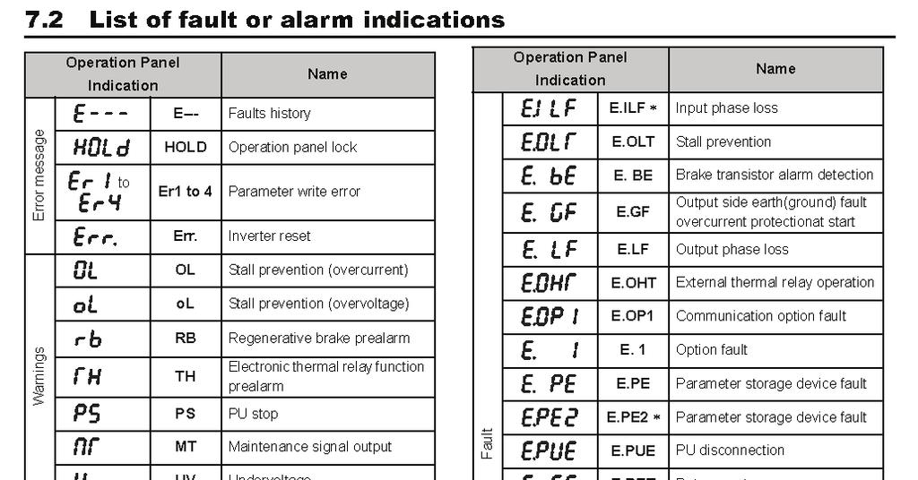
67 Display Screen Error Code Index FAULT CODE DRIVE DISPLAY DERSCRIPTION 0 - No fault 16 E.OC1 Overcurrent trip during acceleration 17 E.OC2 Overcurrent trip during constant speed 18 E.OC3 Overcurrent trip during deceleration or stop 32 E.OV1 Regenerative overvoltage trip during acceleration 33 E.OV2 Regenerative overvoltage trip during constant speed 34 E.OV3 Regenerative overvoltage trip during deceleration or stop 48 E.THT Inverter overload trip (electronic thermal relay function) 49 E.THM Motor overload trip (electronic thermal relay function) 64 E.FIN Fin overheat 82 E.ILF Input phase loss 96 E.OLT Stall prevention 112 E.BE Brake transistor alarm detection 128 E.GF Output side earth (ground) fault overcurrent at start 129 E.LF Output phase loss 144 E.OHT External thermal relay operation 145 E.PTC PTC thermistor operation 176 E.PE Parameter storage device fault (control circuit board) 177 E.PUE PU disconnection 178 E.RET Retry count excess 192 E.CPU CPU fault 196 E.CDO Output current detection value exceeded 197 E.IOH Inrush current limit circuit fault 199 E.AIE Analog input fault 201 E.SAF Safety circuit fault
68 Prior to any repair work on the machine and its drives, secure the machine against unintentional powering on. Problem Possible cause Remedy Excessive Imbalance due to worn or Replace all worn or broken Vibration broken grinding tools. parts. Screws worked loose on the grinding disc. Unusual noises Defective bearing. Wrong tension of the V- belt. Defective motor bearing. Debris deposit on the coupling. Tighten the countersunk head screws on the grinding disc. Check the bearing on the axle drive shaft and replace if necessary. Check the tension of the V- belt; replace the V-belt if necessary. Reduced or no grinding performance Grinding tools have reached the maximum permissible wear. Inappropriate grinding tool for the application. Not enough tension on the V-belt. Change the motor. Clean the coupling. Replace the worn parts. Replace the grinding tools with appropriate tools for the surface to be treated. Re-tension the V-belt. Work on electrical equipment may only be undertaken by a skilled electrician or by a trained person under the supervision of an electrician, as well as in accordance with the local electrical engineering regulations.
69 Prior to any repair work on the machine and its drives, secure the machine against unintentional powering on. Problem Possible cause Remedy Motor does not Missed phase Check the main power supply switch on and switch on again Replace Defective component defective component Motor triggers while running Motor protections switch triggered because of overload Motor has defect Reduce additional load Screen Goes Blank Lost Phase Check the motor Check for 3 legs power No voltage reading on Dis- Loose connection Check pin connectors on interface
 SASE Planetary Diamond Grinders PDG 4500 230 volt 50/60 HZ single phase 8464.20.")
70 Corporate Office th Ave South Kent, WA (P) (F) Certificate of Declaration and Conformity: (Applies to Europe only) SASE Planetary Diamond Grinders PDG volt 50/60 HZ single phase PDG volt 50/60 HZ three phase PDG volt 50/60 HZ three phase PDG volt 50/60 HZ three phase PDG volt 50/60 HZ three phase PDG volt 50/60 HZ three phase PDG volt 50/60 HZ three phase SASE Company hereby certifies that the above listed Planetary Diamond Grinders are classified within the following EU directives of conformity for CE markings: EU Machinery directive 2006/42/EC EU Low voltage directive 2006/95/EC EU Electromagnetic compatibility directive 2004/108/EC and further conform with the following EU Harmonized Standards: EN :2007 EN : A1:2009 EN :2007 EN :2007
71 SASE MANUFACTURER S WARRANTY POLICY Included in this warranty are the following pieces of equipment: Planetary Diamond Grinders: PDG 8000, PDG 6000, PDG 5000, Edge Pro 180 Dust Extractors: Bull 1250, Bull 300, Bull 45 Our Commitment to our customer: SASE Company ( SASE ) equipment is warranted to be free of defects in workmanship and materials for a period of one (1) year from original date of purchase. In the event that you should have a claim SASE shall repair, replace or remedy the defective parts resulting from the faulty design, materials or workmanship. Note: This warranty is only valid for equipment either sold by SASE or by an authorized wholesaler or distributor. Limitations: Warranty does not apply to cosmetic damage, damage due to lightning, electrical surgmisuse, abuse, repair or alteration by other than factory service (unless service center was approved in writing by SASE), negligence, or improper or neglected maintenance as recommended by SASE. Common wear parts, such as belts, bearexempt from warranty. SASE is not responsible for loss of income or down time as a result faulty design, materials or workmanship. Warranty coverage is valid once a warranty SASE. A $100 labor charge may be assessed on the items returned for warranty repair in which no fault is found. Freight charges and associated fees will then become the responsibility of the customer in such an instance. Damages which are caused during transportation are not covered under warranty. Such carrier. Claims: In the unlikely event that you should experience a defect please contact your SASE representative or a SASE service technician by calling Please have all pertinent information readily available such as, invoice with date of purchase, model and serial number, and an explanation of the issue. SASE will respond immediately with a corrective action. Freight responsibility for approved warranty claims: If the piece of equipment was purchased within 90 days of warranty claim, SASE will arrange for ground freight and will assume all ground freight charges to send the customer the parts required or to send the equipment to an authorized SASE repair center. This includes inbound and outbound ground freight and all fees (duties, fuel surcharges) associated with the shipment. If the piece of equipment was purchased beyond 90 days and prior to one (1) year of warranty claim, SASE will cover 50% of all ground freight charges, including inbound and outbound freight and all fees (duties, fuel surcharges) associated with the shipment.
72 SASE PRODUCT & WARRANTY REGISTRATION WARRANTY IS VOID IF NOT RETURNED AND REGISTERED WITH SASE WITHIN 30 DAYS OF PURCHASE COMPANY NAME AND TITLE STREET ADDRESS CITY STATE ZIP COUNTRY PHONE DATE OF PURCHASE SERIAL NUMBER INVOICE NUMBER OF PURCHASE PDG 8000 PDG 6000 PDG 5000 EDGE PRO 180 SC8E SC10E SC12E BULL 1250 BULL 300 BULL 45 PLEASE FILL OUT IN FULL AND SUBMIT TO: SASE COMPANY 2475 STOCK CREEK BLVD ROCKFORD TN, FAX: QUESTIONS? CALL
Safety Instructions Introduction Transportation Storage Setup and Operation Changing of Diamonds...
 Table of Contents Safety Instructions... 2 Introduction... 4 Transportation... 4 Storage... 4 Setup and Operation... 5 Changing of Diamonds... 7 Determining Diamond Selection... 9 Final Assembly... 11
PDG Manual. SASE Company, Inc. Phone or Fax
 PDG 9500+ Manual SASE Company, Inc. Phone 800.522.2606 or Fax 877.762.0748 www.sasecompany.com Version 5 Ser. #: 2300 + Date : 8/1/2018 Table of Contents Cover... 1 Letter from SASE Safety Instructions
PDG V PLANETARY EDGER. SASE Company, Inc. Phone or Fax
 PDG 3000 460V PLANETARY EDGER SASE Company, Inc. Phone 800.522.2606 or Fax 877.762.0748 www.sasecompany.com Version 1.2 9/27/2017 Corporate Office Details 26423 79th Ave South Kent, WA 98032-7321 1.800.522.2606
Corporate Office th Ave South Kent, WA (P) (F) sa ny.
 (F) sa ny.") Version 7.3 Ser. #: 2000 to 3000 Date: 01/01/2018 2 -.' ---... *SASE. Corporate Office 26423 79 th Ave South Kent, WA 98032-7321 1.800.522.2606 (P) 1.877.762.0748 (F) www.sasecompany.com sa les@sasecompa
Version 7.3 Ser. #: 2000 to 3000 Date: 01/01/2018 2 -.' ---... *SASE. Corporate Office 26423 79 th Ave South Kent, WA 98032-7321 1.800.522.2606 (P) 1.877.762.0748 (F) www.sasecompany.com sa les@sasecompa
PDG 5000 PROPANE MANUAL
 PDG 5000 PROPANE MANUAL SASE Company, Inc. 800.522.2606 www.sasecompany.com SAFETY WARNING: Operate in large open ventilated areas only. Must not be run indoors or enclosed areas. Introduction The SASE
PDG 5000 PROPANE MANUAL
 PDG 5000 PROPANE MANUAL SASE Company, Inc. 800.522.2606 www.sasecompany.com Version: 5K04R3 Serial: 2000-2500 4/27/2018 2 -.' ---... *SASE. Corporate Office 26423 79 th Ave South Kent, WA 98032-7321 1.800.522.2606
MODEL 83 Pail Handler
 MORSE MFG. CO., INC. 727 West Manlius Street P.O. Box 518 East Syracuse, NY 13057-0518 Phone: 315-437-8475 Fax: 315-437-1029 Email: service@morsemfgco.com Website: www.morsemfgco.com COPYRIGHT 2005 MORSE
HOLE CUTTER SHARPENER ASSEMBLY & SERVICE MANUAL
 HOLE CUTTER SHARPENER ASSEMBLY & SERVICE MANUAL WARNING You must thoroughly read and understand this manual before operating the equipment, paying particular attention to the Warning & Safety instructions.
VARIABLE SPEED WOOD LATHE
 MODEL MC1100B VARIABLE SPEED WOOD LATHE INSTRUCTION MANUAL Please read and fully understand the instructions in this manual before operation. Keep this manual safe for future reference. Version: 2015.02.02
CONCRETE SAW PARTS LIST
 CONCRETE SAW PARTS LIST MODEL CCXL-EE December 01 Part # 1 Intentionally Blank Table of Contents Description Page No. Frame Assembly... Carriage Assembly Motor Assembly.... Blade Shaft Assembly... Spring
DUAL HEAD FLOOR GRINDER PARTS LIST MODEL CC200
 DUAL HEAD FLOOR GRINDER PARTS LIST MODEL CC00 September 0 Part #8000 Table of Contents Description Page No. Frame Assembly.. - Disc Assembly..... 6 Flange Assembly.. Engine Group, 0 HP HondaGas. 8 Gear
MODELS: CC3730TE / CC3740TE
 DIAMOND P R O D U C T S CONCRETE SAW PARTS LIST MODELS: CC0TE / CC0TE February 00 Part #00 Table of Contents Pictorial Page Index....., Belt Guard Assembly... Controls Legend....... Belt Tensioner Assembly....
DIAMOND MODEL CC1900 EARLY ENTRY CONCRETE SAW PARTS LIST P R O D U C T S. (March 2012) Part #
 Part #") DIAMOND P R O D U C T S EARLY ENTRY CONCRETE SAW PARTS LIST MODEL CC1900 (March 2012) Part #1801617 (Intentionally Blank) TABLE OF CONTENTS Description Page No. Frame Assembly....4-5 Engine Assembly......6
DIAMOND P R O D U C T S EARLY ENTRY CONCRETE SAW PARTS LIST MODEL CC1900 (March 2012) Part #1801617 (Intentionally Blank) TABLE OF CONTENTS Description Page No. Frame Assembly....4-5 Engine Assembly......6
CONCRETE SAW PARTS LIST
 CONCRETE SAW PARTS LIST MODEL CC00XL ELECTRIC & HYDRAULIC UNITS August, 0 Part # 0 Table of Contents Common Parts.. Front Axle Assembly... Rear Axle Assembly... Transmission Assembly... Blade Shaft Assembly
Angle Grinder. Model Visit our website at:
 Angle Grinder Safety Guard Model 45921 Installation Instructions Note: Cutting Blade and Angle Grinder sold separately. Visit our website at: http://www.harborfreight.com Read this material before using
VARIABLE SPEED WOOD LATHE. Model DB900 INSTRUCTION MANUAL
 VARIABLE SPEED WOOD LATHE Model DB900 INSTRUCTION MANUAL 1007 TABLE OF CONTENTS SECTION...PAGE Technical data.. 1 General safety rules....1-3 Specific safety rules for wood lathe.....3 Electrical information.4
3/8 Butterfly Air Impact Wrench
 3/8 Butterfly Air Impact Wrench 37730 ASSEMBLY AND OPERATING INSTRUCTIONS 3491 Mission Oaks Blvd., Camarillo, CA 93011 Visit our Web site at http://www.harborfreight.com Copyright 2004 by Harbor Freight
10" Wet Tile Cutting Saw
 8035735 10" Wet Tile Cutting Saw Owner s Manual Read and understand all instructions before operation. Keep this manual for future reference pg. 2 SPECIFICATIONS ITEM DESCRIPTION Overall Dimensions (saw
INSTRUCTION BOOKLET AND WARRANTY INFORMATION 6 BENCH GRINDER
 INSTRUCTION BOOKLET AND WARRANTY INFORMATION 6 BENCH GRINDER Part No.: SW1250 PLEASE READ CARE AND SAFETY INSTRUCTIONS BEFORE USE SPECIFICATIONS Part No.: SW1250 Input Voltage: 240V Frequency: 50Hz Rated
TABLE OF CONTENTS DESCRIPTION. Safety Instructions Assembly Operation... 7
 TABLE OF CONTENTS DESCRIPTION PAGE Warranty... 1 Safety Instructions... 2 Assembly... 3 Operation... 7 #360 Grain Cleaner Drawings... 8 #360 Grain Cleaner Parts List... 10 Utility Auger Option Drawing...
CAUTION! This manual contains important information for the correct installation, operation and maintenance of the equipment described herein.
 CAUTION! This manual contains important information for the correct installation, operation and maintenance of the equipment described herein. All persons involved in such installation, operation, and
Trautman Carvers. Product Manual
 Trautman Carvers Product Manual Contents Product Specifications.... 4 Operating Precautions.... 6 Floor Carver Use.... 7 Floor Carver Diagram.... 10 Trautman Motor Lift Assist.... 11 Use of the Lift Assist....
EllisSaw.com. EllisSaw.com P.O. Box Verona, WI
 P.O. Box 9019 Verona, WI 9-019 GENERAL OPERATING & SAFETY INSTRUCTIONS * READ INSTRUCTIONS BEFORE USE * CAUTION: Disconnect power supply cord from power source when doing repair work or changing belt.
GENERAL OPERATIONAL PRECAUTIONS PRECAUTIONS ON USING CUT-OFF MACHINE
 GENERAL OPERATIONAL PRECAUTIONS WARNING! When using electric tools, basic safety precautions should always be followed to reduce the risk of fire, electric shock and personal injury, including the following.
30AUTO Speed Lathe Manual
 30AUTO Speed Lathe Manual Standard Features 3/4 HP Motor Air-Collet Closure 1800 RPM, Single Speed Electric Brake Cast Housing 5C Collets 3 Phase / 240 Volts DESCRIPTION: The Crozier Model 30AUTO Automotive
TUCANA-02 P PORTABLE END MILLING MACHINE USER S MANUAL
 TUCANA-02 P PORTABLE END MILLING MACHINE USER S MANUAL 1 CONTENTS Page 1. General Information 3 1.1. Introduction 3 1.2. Manufacturer 3 2. Machine s Description and Purpose of Use 3 2.1. Machine s description
Square Wheel Belt Grinder Models: 4103, 4106, and 4126AC
 This Manual is Bookmarked Operating Instructions Parts Manual Square Wheel Belt Grinder Models: 4103, 4106, and 4126AC WHM TOOL GROUP 2420 Vantage Drive Elgin, Illinois 60123 Ph.: 800-274-6848 www.wmhtoolgroup.com
Item# " VARIABLE SPEED BENCH GRINDER USER'S MANUAL
 Power Tools Item# 33309 3" VARIABLE SPEED BENCH GRINDER USER'S MANUAL Read carefully and understand RULES FOR SAFE OPERATION and instructions before operating. Failure to follow the safety rules and other
32 FRONT DECK ASSEMBLY
 3 6 K 2 0 PARTS MANUAL 32 FRONT DECK ASSEMBLY 3 1 2 Belt Shield Prior to SN 33333 4 6 21 22 7 24 2 26 14 8 13 12 9 10 11 27 2 28 1 16 2 19 17 30 36 39 39 37 29 60 62 61 3 9 49 41 40 28 48 42 13 43 44 47
The DeltaGrip System. Safety and Operating Instructions. Trigger. Air Supply Connection. Handle Assembly. Air Line Assembly.
 The DeltaGrip System Safety and Operating Instructions Trigger Air Supply Connection Handle Assembly Air Line Assembly Punch Die Pneumatic Diaphragm Assembly Shackle, Pin & Jam Nut Jaw Frame Shoulder Screw
Walk-Behind Lawn Mowers
 Walk-Behind Lawn Mowers Parts Manual Models 2 - PRO21SCH 12 - LM21 1 - LM21S 1 - LM21SW 1 - LM21S 11 - PRO21SCH 0 - LM21SW - LM21S - LM21SW 5 - LM21S - LM21SW 0700 /0 Printed in USA THE MANUAL Before you
GENERAL OPERATIONAL PRECAUTIONS PRECAUTIONS ON USING DISC GRINDER
 GENERAL OPERATIONAL PRECAUTIONS WARNING! When using electric tools, basic safety precautions should always be followed to reduce the risk of fire, electric shock and personal injury, including the following.
DIAMOND CONCRETE SAW PARTS LIST MODEL CC1113-XL P R O D U C T S. June Part #
 DIAMOND P R O D U C T S CONCRETE SAW PARTS LIST MODEL CC1113-XL June 013 Part #10 TABLE OF CONTENTS Description Page No. Saw Assembly (Normal Cut).... - Saw Assembly (Up-Cut)...... - Gas Engine Assembly......
INSTRUCTION BOOK AND PARTS LIST
 Rag Cutter MODEL WE WARNING This machine is equipped with a very sharp knife. Keep hands, arms, and hair away from the knife area at all times. Misuse of this machine or failure to follow all safety instructions
STEEL BLASTER CABINET FLOOR MODEL
 STEEL BLASTER CABINET FLOOR MODEL 39170 ASSEMBLY & OPERATING INSTRUCTIONS 3491 Mission Oaks Blvd., Camarillo, CA 93011 Visit our Web Site at www.harborfreight.com Copyright 1998 by Harbor Freight Tools.
VARIABLE SPEED BECH LATHE
 VARIABLE SPEED BECH LATHE Instruction Manual Please read this instruction manual thoroughly and follow all directions carefully. 1 Important Safety Instructions READ ALL INSTRUCTIONS AND WATNINGS BEFORE
 GENERAL OPERATIONAL PRECAUTIONS WARNING! When using electric tools, basic safety precautions should always be followed to reduce the risk of fire, electric shock and personal injury, including the following.
SMALL GAUGE NIBBLER ASSEMBLY & OPERATING INSTRUCTIONS Mission Oaks Blvd., Camarillo, CA Visit our Web Site at
 SMALL GAUGE NIBBLER 91739 ASSEMBLY & OPERATING INSTRUCTIONS 3491 Mission Oaks Blvd., Camarillo, CA 93011 Visit our Web Site at www.harborfreight.com Copyright 2004 by Harbor Freight Tools. All rights reserved.
24 GA. PITTS ROLLFORMER
 1 TIN KNOCKER 24 GA. PITTS ROLLFORMER INSTRUCTIONS & PARTS DIAGRAM Shown with Stand and Optional Flanging Attachment Rev. 092606 TAAG MACHINERY CO. (Master Distributor) 1257-B Activity Dr. Vista, CA 92081
ABM International, Inc. Navigator Assembly Manual
 ABM International, Inc. 1 1.0: Parts List Tablet (Qty. 1) Tablet mount (Qty. 1) NOTE: Mount may appear and operate different then image below Control Box (Qty. 1) Motor Power Supply (Qty. 1) 2 X-axis motor
Owner s Manual ODYSSEY BENCH MODEL. O4100B shown REV E. Southern Avenue, Phoenix, AZ USA Workhorseproducts.
 Owner s Manual ODYSSEY BENCH MODEL O4100B shown 67-1375 REV 218 3730 E. Southern Avenue, Phoenix, AZ 85040 USA 800-778-8779 Workhorseproducts.com 1 Table of Contents I. Introduction & Safety Information.
SECTION 7 - SUSPENSION
 For Arctic Cat Discount Parts Call 606-678-9623 or 606-561-4983 SECTION 7 - SUSPENSION TABLE OF CONTENTS Section Front and Rear Suspension Assembly Schematics... 7-2 Shock Absorbers... 7-4 Swing Arms (ACT
JARVIS. Model H080 Carcass Splitting Band Saw
 Carcass Splitting Band Saw EQUIPMENT SELECTION... Ordering No. TABLE OF CONTENTS... Page... See Table 1, Page 4 Balancer... 4042042 Band Saw Blade... 1023099 Notice to Employer and Safety Director... 2
30DC Speed Lathe Manual
 30DC Speed Lathe Manual The Crozier Model 30DC Speed Lathe is our most popular model. It has many standard features not found on any other machine in its class or price range. Standard Features 3/4 HP
Tapping Screw (W/Flange) 46 Cord Armor 47 Tube (D) 48 Cord. 45 Cord Clip. Tapping Screw (W/Flange) 10 Gear Cover Ass'y. 12 Socket (B) Ass'y
 46 Cord Armor 47 Tube (D) 48 Cord. 45 Cord Clip. Tapping Screw (W/Flange) 10 Gear Cover Ass'y. 12 Socket (B) Ass'y") W8VB The exploded assembly drawing should be used only for authoized service center. W8VB Item No. Part time 1 Magnetic Hex. Socket 2 Sub Stopper 3 O-Ring (S-16) 4 Locator (A) 5 Lock Sleeve (A) 6 O-Ring
W8VB The exploded assembly drawing should be used only for authoized service center. W8VB Item No. Part time 1 Magnetic Hex. Socket 2 Sub Stopper 3 O-Ring (S-16) 4 Locator (A) 5 Lock Sleeve (A) 6 O-Ring
TABLE OF CONTENTS DESCRIPTION. Safety Instructions Assembly Operation... 7
 TABLE OF CONTENTS DESCRIPTION PAGE Warranty... 1 Safety Instructions... 2 Assembly... 3 Operation... 7 #360 Grain Cleaner Drawings... 8 #360 Grain Cleaner Parts List... 10 Utility Auger Option Drawing...
Parts Manual for: MODELS / I.D. : / ZTH5223A / ZTH5225A / ZTH6125A
 Parts Manual for: MODELS / I.D. : 968999153 / ZTH5223A 968999154 / ZTH5225A 969999155 / ZTH6125A Husqvarna policy is to improve its products whenever it is possible and practical to do so. In an effort
Specifications. Important Safety Information
 Specifications Tire Rim Capacity 4 to 12 Rim Height 16 (2) Bead Breaker Handles 21 Long Includes Aluminum Centering Cone (2) Nylon Spacers Important Safety Information 1. Do not exceed max. tire capacity.
Core EZ. Operating Manual. Toll Free B East Broadway Avenue Tampa, FL 33619
 Operating Manual 3702 West Central Avenue Santa Ana, CA 92704 Toll Free 1-866-987-7297 11 High Street Suffield, CT 06078 www.ussaws.com 8004B East Broadway Avenue Tampa, FL 33619 Introduction This manual
8 Buffer. Set up and Operating Instructions. (Buffing Wheels Not Included) Distributed exclusively by Harbor Freight Tools.
 Distributed exclusively by Harbor Freight Tools.") 8 Buffer 40668 Set up and Operating Instructions (Buffing Wheels Not Included) Distributed exclusively by Harbor Freight Tools. 3491 Mission Oaks Blvd., Camarillo, CA 93011 Visit our website at: http://www.harborfreight.com
8 Buffer 40668 Set up and Operating Instructions (Buffing Wheels Not Included) Distributed exclusively by Harbor Freight Tools. 3491 Mission Oaks Blvd., Camarillo, CA 93011 Visit our website at: http://www.harborfreight.com
Parts Manual for MODELS: ZKH52222 ZKH52252 ZKH61252
 Parts Manual for MODELS: ZKH52222 ZKH52252 ZKH61252 Professional Quality Lawn Care Equipment since 1945 THIS MANUAL INCLUDES UPDATES ON PAGES 6,10, & 20. Yazoo/Kees Power Equipment policy is to improve
Instructions for Stone Cutting Machine
 Technical data Kg. Instructions for Stone Cutting Machine SCM600 3HP 2800rpm IP55 SCM800 3HP 2800rpm IP55 SCM1000 2800rpm IP55 SCM1200 2800rpm IP55 L=600 B=85(165) L=800 B=85(175) 500x510 0 or 45 600lt/h
Parts Manual SPDZTR 42 / SPDZTR 42 BF /
 Parts Manual SPDZTR 42 / 966657601 SPDZTR 42 BF / 966657701 Please read the operator s manual carefully and make sure you understand the instructions before using the machine. Gasoline containing up to
Angle Grinder MODEL 9553B MODEL 9555B
 ENGLISH Angle Grinder MODEL 9553B MODEL 9555B 006649 DOUBLE INSULATION I N S T R U C T I O N M A N U A L WARNING: For your personal safety, READ and UNDERSTAND before using. SAVE THESE INSTRUCTIONS FOR
TRAUTMAN CARVERS. from Fillauer LLC PRODUCT MANUAL
 TRAUTMAN CARVERS from Fillauer LLC PRODUCT MANUAL TABLE OF CONTENTS INTRODUCTION General Specifications...4-5 Operating Precautions.... 6 Floor Carver Use...7-9 Uncrating & Set-Up Instructions Operation
PARTS LIST MS 2892-D
 PARTS LIST MS 89-D 8--00 8-0-000 KNIFE BRACE (TOP) 8--00 RIGHT KNIVE (UHMW) 8--00 LEFT KNIFE (UHMW) 8-0-00 KNIFE BRACE (UNDER) NC0-8-0 0 FLAT HEAD SOCKET CAP SCREW STAINLESS /8- X " LG NC0-9-00 0 LOCK
.com. More than a machine. Power your life. Operating Manual
 Operating Manual www.maxnovomachine +86-514-87892928 info@maxnovomachine Dear Customer, Thank you very much for purchasing a product made by MAXNOVO MACHINE. Our machines offer a maximum of quality, technical
WALK-BEHIND SPREADER 50 LB. CAPACITY Model 99623
 WALK-BEHIND SPREADER 50 LB. CAPACITY Model 99623 Assembly, Operating, and Maintenance Instructions Diagrams within this manual may not be drawn proportionally. Due to continuing improvements, actual product
SERVICE PARTS LIST PAGE 1 OF 6 BASE ASSEMBLY SPECIFY CATALOG NO. AND SERIAL NO. WHEN ORDERING PARTS 12" DUAL BEVEL COMPOUND MITER SAW B27B
 PAGE 1 OF 6 BASE ASSEMBLY 00 0 EXAMPLE: Component Parts (Small #) Are Included When Ordering The Assembly (Large #). SPECIFY CATALOG NO. AND NO. WHEN ORDERING PARTS = Part number change from previous service
SAM. Model: STV-C65 LCD Mobile Visualized Stand Instruction Manual. Weight Capacity: 1251bs / 56.7kg Suits LCD Flat Panel Display: 42"-55" Page 20
 SAM Model: STV-C65 LCD Mobile Visualized Stand Instruction Manual Weight Capacity: 1251bs / 56.7kg Suits LCD Flat Panel Display: 42"-55" 20 Step 6 LCD Mobile Lift Stand Model: STV-C65 Cable management
HAND HELD SAW W MILL
 HAND HELD SAW W MILL 92247 ASSEMBLY AND OPERATING INSTRUCTIONS 3491 Mission Oaks Blvd., Camarillo, CA 93011 Visit our Web site at http://www.harborfreight.com Copyright 2004 by Harbor Freight Tools. All
CONCRETE SAW PARTS LIST
 CONCRETE SAW PARTS LIST MODEL CC00 Electric/Hydraulic April, 0 Part # Blade / Engine Speed (RPM) Chart Model CC00 Concrete Saw CAUTION: Do not exceed Bladeshaft speed (RPM) shown for each blade size. Excessive
HANDHOLE SEAT GRINDER
 1041-1601 HANDHOLE SEAT GRINDER OPERATING INSTRUCTIONS & SERVICE MANUAL Rev: A, 9/17/2007 TO REDUCE THE RISK OF INJURY AND EQUIPMENT DAMAGE USER MUST READ AND UNDERSTAND OPERATOR S MANUAL. Thomas C. Wilson,
JARVIS. Model Buster IV Forequarter Beef Splitting Band Saw Installation Instructions... 9 TABLE OF EQUIPMENT
 Beef Splitting Band Saw EQUIPMENT SELECTION............. Ordering No. TABLE OF CONTENTS......................... Page Buster IV Forequarter Saw.... 4006058 Spring Balancer............. 4042023 Blade......................
ATBG280/6 Bench Grinder Bench Grinder ATBG280/6 230V-50Hz 280 Watt 150mm x 25mm Wheel size
 Bench Grinder ATBG280/6 230V-50Hz 280 Watt 150mm x 25mm Wheel size SPECIFICATIONS Model Number : ATBG280/6 Nominal Voltage Power Consumption No load speed Wheel size Weight 230Volt 50Hz 280 Watts 2880
1300-lb Furniture and Crate Movers
 1300-lb Furniture and Crate Movers Owner s Manual WARNING: Read carefully and understand all ASSEMBLY AND OPERATION INSTRUCTIONS before operating. Failure to follow the safety rules and other basic safety
JARVIS. Model Buster V Loin Drop Beef Loin Dropping Saw
 Beef Loin Dropping Saw EQUIPMENT SELECTION... Buster V Loin Drop Saw Ordering No. 230V, 60Hz Model... 4006051 460V, 60Hz Model... 4006060 575V, 60Hz Model... 4006087 Spring Balancer... 4042038 Blade (133
COMMERCIAL MOWERS PARTS MANUAL FOR: MODELS: ZKH52221 ZKH52251 ZKH61221 ZKH61251
 PARTS MANUAL FOR: COMMERCIAL MOWERS MODELS: ZKH52221 ZKH52251 ZKH61221 ZKH61251 FD KEES POWER EQUIPMENT, L.L.C. 700-800 PARK AVENUE BEATRICE, NEBRASKA, U.S.A. 68310 PRINTED IN USA MANUAL NO.-102935 REV.
MODELS 49 RA 49 RAZ 49 RAC
 General Safety and Maintenance Manual MODEL grinder featuring a rear exhaust. Model Number Exhaust Direction REAR Throttle Type (L) Lever or (K) Safety Lever Speed 12000 to 14000 R.P.M (13500rpm is standard)
Powermatic Model 31A Combination Belt-Disk Sander
 OPERATING PROCEDURE FOR: Powermatic Model 31A Combination Belt-Disk Sander INTRODUCTION: The combination belt-disk sander is used to sand the edges of boards. It can be used to smooth the edge or to remove
Cam Handle Service Guide
 Cam Handle Service Guide Page 2. Introduction Page 3. Troubleshooting guide Page 4-5. Adjusting the clamp force Page 6-7. Disassembling, greasing and replacing components Page 8-9. Replacing the post bearings
RYOBI. 10 in. (254 mm) TABLE SAW MODEL NO. BTS15 REPAIR SHEET
 TABLE SAW MODEL NO. BTS15 REPAIR SHEET") RYOBI 0 in. ( mm) TABLE SAW MODEL NO. BTS REPAIR SHEET FIGURE A 0 0 0 0 The model number will be found on a plate attached to the motor housing. Always mention the model number in all correspondence regarding
RYOBI 0 in. ( mm) TABLE SAW MODEL NO. BTS REPAIR SHEET FIGURE A 0 0 0 0 The model number will be found on a plate attached to the motor housing. Always mention the model number in all correspondence regarding
PLATE JOINER 4 INCH. ASSEMBLY and OPERATING INSTRUCTIONS. Distributed Exclusively by Harbor Freight Tools
 PLATE JOINER 4 INCH 38437 ASSEMBLY and OPERATING INSTRUCTIONS Distributed Exclusively by Harbor Freight Tools 3491 Mission Oaks Blvd., Camarillo, CA 93011 Copyright 1998 by Harbor Freight Tools. All rights
18 GAUGE ELECTRIC METAL SHEAR
 241-9895 18 GAUGE ELECTRIC METAL SHEAR Operator s Manual SAVE THIS MANUAL You will need this manual for safety instructions, operating procedures and warranty. Put it and the original sales receipt in
GENERAL OPERATIONAL PRECAUTIONS
 GENERAL OPERATIONAL PRECAUTIONS WARNING! When using electric tools, basic safety precautions should always be followed to reduce the risk of fire, electric shock and personal injury, including the following.
DIAMOND MODEL CC1300-XL P R O D U C T S CONCRETE SAW PARTS LIST. March Part#:
 DIAMOND P R O D U C T S CONCRETE SAW PARTS LIST MODEL CC1300-XL March 2007 Part#: 1800666 Intentionally Blank Table of Contents Description Page No. Frame Group....4-7 Engine Group 9 Horsepower Gas. 8
Please read BOTH these Installation Instructions and the General Instructions prior to installing or operating this equipment.
 Attachment Tab Height: 16-1/2 Serial Number Attachment Tab Width: 24 Please read BOTH these and the General Instructions prior to installing or operating this equipment. 1. Blue Ox towing products and
JARVIS. Model BR-3 Blade Reconditioner ... EQUIPMENT TABLE OF
 - Model BR-3 Blade Reconditioner EQUIPMENT SELECTION.......... Ordering No. TABLE OF CONTENTS............................ Page Model BR-3 (100 mm Blade) 115V/60Hz............ 4011003 220V/50Hz............
Tire Chain Kit. Replacing Shear Pins. Weight Kits. Drift Cutter
 Replacing Shear Pins The augers are secured to the spiral shaft with two shear pins and cotter pins. If the auger should strike a foreign object or ice jam, the snow thrower is designed so that the pins
DUST COLLECTOR 70 GALLON, 2 HP
 DUST COLLECTOR 70 GALLON, 2 HP Model 45378 ASSEMBLY AND OPERATING INSTRUCTIONS 3491 Mission Oaks Blvd., Camarillo, CA 93011 Visit our Web site at http://www.harborfreight.com Copyright 2001 by Harbor Freight
Operating Instructions and Parts Manual SLT-1100 Jumbo Scissor Lift Table
 Operating Instructions and Parts Manual SLT-1100 Jumbo Scissor Lift Table JET 427 New Sanford Road LaVergne, Tennessee 37086 Part No. M-140780 Ph.: 800-274-6848 Revision B1 05/2014 www.jettools.com Copyright
C a r r i a g e A s s e m b l y R e p l a c e m e n t
 E1 TF-CR C a r r i a g e A s s e m b l y R e p l a c e m e n t October 2007 Software Version 5.0 and higher IMPORTANT! TigerStop must be enabled with a code that must be obtained from TigerStop Customer
12mm (Max) 6mm (Max) 82mm (Max) 12mm (Max) 6mm (Max)
 6mm (Max) 82mm (Max) 12mm (Max) 6mm (Max)") 1 1 2 2 3 3 82mm (Max) 12mm (Max) 12mm (Max) 6mm (Max) 4 4 5 6 8 6mm (Max) 0.5 0mm 1 5 6 7 7 8 9 9 A = B 10 11 12 D B 1 13 14 15 0 C A D E 16 17 18 F G D B N H J G I K 19 A 20 G L 21 C K 1mm L M 1mm 22
1 1 2 2 3 3 82mm (Max) 12mm (Max) 12mm (Max) 6mm (Max) 4 4 5 6 8 6mm (Max) 0.5 0mm 1 5 6 7 7 8 9 9 A = B 10 11 12 D B 1 13 14 15 0 C A D E 16 17 18 F G D B N H J G I K 19 A 20 G L 21 C K 1mm L M 1mm 22
BUY PARTS ONLINE AT GRIZZLY.COM!
 SECTION 9: PARTS Tables, Fence & Cutterhead 28 29 26 27 25 23 23 22 24 22 35 37 36 38 16 15 17 18 39 11 14 19 20 21 13 12 6 7 8 9 10 1 2 5 49 3 4 3 31 30 6 7 94 93 95 40 96 43 42 44 45 46 47 48 55 55-4
ATV CULTIVATOR OWNER S MANUAL
 ATV CULTIVATOR OWNER S MANUAL WARNING: Read carefully and understand all ASSEMBLY AND OPERATION INSTRUCTIONS before operating. Failure to follow the safety rules and other basic safety precautions may
Operating, Servicing, and Safety Manual Model # 100 Standard Hydraulic Tubing Notcher Model #100-U Heavy Duty Hydraulic Tubing Notcher
 Operating, Servicing, and Safety Manual Model # 100 Standard Hydraulic Tubing Notcher Model #100-U Heavy Duty Hydraulic Tubing Notcher Model # 100 Standard Model #100-U Heavy Duty CAUTION: Read and Understand
Parts Manual RZ4623 /
 Gasoline containing up to 10% ethanol (E10) is acceptable for use in this machine. The use of any gasoline exceeding 10% ethanol (E10) will void the product warranty. Parts Manual RZ4623 / 967009801 Please
Parts Catalog. S-Series Slicer Smart Manual SG13. Model:
 , 07 99507 ECN 065 Parts Catalog S-Series Slicer Smart Manual Model: SG SG 0/0/07 Rev. G IMPORTANT! TO EXPEDITE SHIPMENT OF PARTS, ALWAYS SPECIFY MODEL, REV, PART NUMBER, AND SERIAL NUMBER OF UNIT. GLOBE
E.C. HOPKINS LTD PGO4 PEANUT GRINDER OPERATORS MANUAL AND PARTS LIST
 E.C. HOPKINS LTD PGO4 PEANUT GRINDER OPERATORS MANUAL AND PARTS LIST E.C. HOPKINS LTD UNIT 1, 82 KETTLES WOOD DRIVE, WOODGATE BUSINESS PARK, WOODGATE VALLEY, BIRMINGHAM B32 3DB TEL NO. +44 (0)121 506 6095
SAVE THIS FOR FUTURE REFERENCE THIS PRODUCT IS FOR PROFESSIONAL LABORATORY USE ONLY USER'S MANUAL
 DENTAL, INC. TECHNICAL BULLETIN G801-022510 5860 FLYNN CREEK ROAD READ ALL INSTRUCTIONS P.O. BOX 106 BEFORE PROCEEDING COMPTCHE, CALIFORNIA, U.S.A. 95427-0106 SAVE THIS FOR FUTURE REFERENCE www.wellsdental.com
OPERATOR S MANUAL MAINTENANCE MANUAL PARTS LIST TURFCO. 60 Inch Seeder. Product Number Starting Serial Number H00801 PATENT PENDING
 0 Inch Seeder OPERATOR S MANUAL MAINTENANCE MANUAL PARTS LIST TURFCO 0 Inch Seeder Product Number 0 Starting Serial Number H000 PATENT PENDING Manual Number DANGER - IF INCORRECTLY USED THIS MACHINE CAN
Please read BOTH these Installation Instructions and the General Instructions prior to installing or operating this equipment.
 Please read BOTH these and the General Instructions prior to installing or operating this equipment. 1. Blue Ox towing products and accessories are intended to be installed by Blue Ox Dealers who are familiar
TABLE OF CONTENTS MODEL 8750/8800 OCL
 TABLE OF CONTENTS MODEL 8750/8800 OCL Warranty Registration...2 Warranty...3 Vehicle Preparation...4 Attaching the Lathe using Universal Plates (8750)...5 Threaded Plates (RED)...6 Unthreaded Plates (BLUE)...7
Parts Catalog. S-Series Slicer Manual Frozen Option S13. Model:
 , 07 995 ECN 08 Parts Catalog S S-Series Slicer Manual Frozen Option Model: S 05/0/07 Rev. G IMPORTANT! TO EXPEDITE SHIPMENT OF PARTS, ALWAYS SPECIFY MODEL, REV, PART NUMBER, AND SERIAL NUMBER OF UNIT.
REPAIR INSTRUCTIONS. Cat. No Cat. No MILWAUKEE ELECTRIC TOOL CORPORATION. SDS Max Demolition Hammer. SDS Max Rotary Hammer
 Cat. No. 9-0 SDS Max Demolition Hammer Cat. No. -0 SDS Max Rotary Hammer MILWAUKEE ELECTRIC TOOL CORPORATION W. LISBON ROAD BROOKFIELD, WISCONSIN 00-0 8-9-0 d 000 8-9-0 d Special Tools Require Forcing
CHAINSAW SHARPENER MODEL: ECSS-1
 CHAINSAW SHARPENER MODEL: ECSS-1 Part No: 3402075 ASSEMBLY & INSTRUCTION MANUAL LS0409 INTRODUCTION Thank you for purchasing this CLARKE product Before attempting to use the product, it is essential that
SERVICE PARTS LIST PAGE 1 OF 6 BASE ASSEMBLY SPECIFY CATALOG NO. AND SERIAL NO. WHEN ORDERING PARTS 12" SLIDING COMPOUND MITER SAW
 PAGE 1 OF 6 BASE ASSEMBLY 00 0 CATALOG NO. EXAMPLE: SPECIFY CATALOG NO. AND NO. WHEN ORDERING PARTS 6955-20 1 02-80-0050 Thrust Bearing (1) 2 05-80-0510 M5 x 12mm Flat Head T-20 Screw (5) 3 05-81-0135
ARROW SAW PRECISE CUT 8000 RPM WITH DUST COLLECTING ATTACHMENT INSTRUCTION BOOK MODEL NO
 ATTENTION If any components of this unit are broken or the unit does not operate properly, please contact Cabela s Customer Service. Retail Store Purchases: 1-800-905-2731 (U.S. & Canada) Catalog and Internet
Hydraulic Renovator 20
 Model #: 704591 Starting Date: 2/2005 8HP Kawasaki Engine Hydraulic Renovator 20 ILLUSTRATED PARTS LIST 2 Handle Assembly - Fig. 1 4 7 19 17 9 1 56 58 1 12 14 55 5 16 21 7 8 27 17 0 26 24 6 2 52 4 15 11
SAFETY AND OPERATING MANUAL
 SAFETY AND OPERATING MANUAL BladeRunner X2 WX572 9 10 8 11 5 7 12 6 20 1 2 4 3 14 13 15 A2 A1 17 18 B2 B1 1 2 1 2 19 B3 3 4 2 C 1 D1 D1 C 2 1 E1 D2 1 2 E2 1 2 F G1 G1 F OFF ON G2 G3 H1 H2 I1 I2 I1 I2 J