Corporate Office th Ave South Kent, WA (P) (F) sa ny.
|
|
|
- Lee Sanders
- 5 years ago
- Views:
Transcription

1 Version 7.3 Ser. #: 2000 to 3000 Date: 01/01/2018
2 2

3 -.' *SASE. Corporate Office th Ave South Kent, WA (P) (F) sa ny.com Congratulations on your decision to get the Power of SASE behind you! SASE is committed to excellence, excellence in the quality of products we sell and excellence in service and support after the sale. It is important to us that your business continues to succeed and grow, and we know that the right products, service and support can have a great impact on your bottom line. SASE has made great strides in the concrete preparation and polishing industry over the years. With a 40,000 square foot distribution and service facility in Seattle, a 22,000 square foot distribution and service faclllty in Knoxville, and local sales and technical support representatives throughout the United States, SASE is able to provide unsurpassed service and technical support for the contractor. At SASE we engineer and manufacture our own equipment, which allows us to be in control of the quality of the equipment we sell. SASE offers a complete line of concrete preparation and polishing equipment, our newest introduction being our new line of PDG planetary diamond grinders, which Is setting a new standard for the concrete grinding and polishing industry. SASE is also the leader in diamond tooling technology. We look forward to a long and prosperous partnership with you! Thank you again for choosing SASE. You won't regret having the Power of SASE behind your company! Sincerely, SASE Company, Inc. Jim Weder President 3
4 Rev 7 4
5 Table of Contents Cover Letter From Owner Table of Contents Introduction; Transportation; Storage Safety Instructions Setup and Operation Changing Diamonds Determine Diamond Selection Diamond Tooling Quick Reference Water System Vacuum System Frame Complete Motor On Drum Handle Stem Drum Complete Top Drum Plate Bottom Drum 1 Bottom Drum 2 Bottom Drum 3 Drum Sheave Top Idler Top Tensioner Intermediate Main Tensioner Main Spindle Main Idler Planetary Flex Head Tooling Belt Paths Troubleshooting Warranty Declaration of Conformity
6 Introduction The SASE PDG 5000 planetary diamond grinders are designed for wet or dry grinding of marble, terrazzo, granite and concrete. Their applications range from rough grinding through to a polished finish. IMPORTANT! It is recommended that machinery be transported with a set It is extremely important all users be familiar with the contents of this of diamonds attached at all times to ensure protection of manual before commencing operation of either machine. Failure to do so may result in damage to machinery or expose operator to unnecessary locking mechanism for diamond plates. dangers. IMPORTANT! Storage The machine should always be stored in a dry place when not in use. Only staff that has received the necessary training, both practically and theoretically concerning their usage should operate the machinery. Transportation The machine comes equipped with an electronic system called a variable speed drive or a frequency converter. The drive enables the variable speed and direction component of the motor. The drive is located in the steel cabinet mounted on the machine chassis. As with all electronic equipment, the drives are sensitive to excessive vibration, rough treatment and high levels of dust. Much care and attention has been given by SASE to ensure maximal protection is given to the drive. Note the shock absorbing mounting system used to mount the steel cabinet on the machine chassis/frame. When transporting, it is important to ensure the machinery is properly secured at all times to eliminate bouncing of the variable speed drive. Ensure the chassis or frame section of the machine is secured down at all times when in transit. The machine should always be transported under cover limiting the exposed to natural elements in particular rain and snow. WARNING The machine should not be lifted by handle, motor, chassis or other parts. Transportation of the machine is best done on a pallet/skid to which the machine must be firmly secured. Do not attempt to slide the tines/forks from a fork lift under grinding heads unless on a pallet/skid. Failure to do so can cause irreparable damage to grinding heads of machine and internal parts. Rev 7 6
7 Safety Instructions Please read the operator s manual carefully and make sure you understand the instructions before using the machine. WARNING! Dust forms when grinding which can cause injuries if inhaled. Use an approved breathing mask. Always provide for good ventilation while machine is in use. Only qualified personnel should be allowed to operate machinery. Never use a machine that is faulty. Carry out the checks, maintenance and service instructions described in this manual. All repairs not covered in this manual must be performed by a repairer nominated by either the manufacturer or distributor. Always wear personal safety equipment such as sturdy non-slip boots, ear protection, dust mask and approved eye protection. The machine should not be used in areas where potential for fire or explosions exist. Always wear: Approved protective helmet. Approved hearing protection. Protective goggles or a visor. Dust Mask Dust forms when grinding, which can cause injuries if inhaled. Always wear approved protective gloves. Machinery should only be started when grinding heads are resting on the ground. The machine should not be started without the rubber dust skirt attached. It is essential a good seal between floor and machine be established for safety, especially when operating in dry grinding applications. When changing the grinding discs ensure power supply to the unit is OFF by engaging the Emergency Stop button and the power-plug disconnected. The machine should not be lifted by handles, motor, chassis or other parts. Transportation of the machine is best done on a pallet / skid to which the machine must be firmly secured. Extreme caution must be used when moving machinery by hand on an inclined plane. Even the slightest slope can cause forces/ momentum making the machinery impossible to brake manually. Always wear sturdy non-slip boots with steel toe-caps. Never use the machine if you are tired, if you have consumed any alcohol, or if you are taking medication that could affect your vision, your judgment or your coordination. Never use a machine that has been modified in any way from its original specification. WARNING Under no circumstances may the machine be started without observing the safety instructions. Should the user fail to comply with these, SASE Company Inc or its representatives are free from all liability both directly and indirectly. Be on your guard for electrical shocks. Avoid having body contact with lightning conductors/metal in the ground. Never drag the machine by means of the cord and never pull out the plug by pulling the cord. Keep all cords and extension cords away from water, oil and sharp edges. Read through these operating instructions and make sure that you understand the contents before starting to use the machine. Should you, after reading these safety instructions, still feel uncertain about the safety risks involved you must not use the machine, please contact your SASE representative for more information. Rev 7 7

8 Safety Instructions Check that the cord and extension cord are intact and in good condition. Never use the machine if the cord is damaged, hand it in to an authorized service workshop for repair. WARNING HIGH VOLTAGE! Does not use a rolled up extension cord. Electrical cords must not exceed 200ft in length. The machine should be connected to an earthed outlet socket. Inspection and/or maintenance should be carried out with the motor switched off and the plug disconnected. Check that the mains voltage corresponds with that stated on the rating plate on the machine. Ensure the cord is behind you when you start to use the machine so that the cord will not be damaged. This product is in accordance with applicable EU directives WARNING At no time should lifting of machinery be attempted without mechanical means such as a hoist or a forklift. Rev 7 8
9 Setup and Operation Planetary rotation direction The correlation between FWD/REV & Clockwise/Counter clockwise rotation can be said as follows if looking at the grinding discs from underneath the machine: REV-Clockwise. FWD-Reverse. As mentioned earlier, when the machine is in operation it will pull to one side. The direction of pull is determined by the planetary head direction of rotation. The head of the machine will pull to the right (and therefore, will be felt on the right hip of the operator) when the planetary head is set in the REVERSE direction. This sideways pull can be very useful when grinding, particularly along a wall. Set the machine so that it pulls towards the wall, and then control the machine so it can just touch the wall. This will ensure a grind close to the wall or object. Direction is also a matter of personal preference, however to improve the cutting efficiency of diamonds, change directions on a regular basis. This will work both sides of the diamond crystals, keeping the abrasives as sharp as possible by creating maximal exposure of the diamond crystal. Once both a speed and direction have been nominated, switch on dust extraction or vacuum device. IMPORTANT! It is highly recommended to use a SASE BULL 1250 Industrial Vacuum system for complete dust control. Rev 7 9


. 3.")
10 Changing of Diamonds Different applications often require different selections of diamond tooling. There will be many occasions when the grinding discs need to be changed. Following is a guide for this procedure. Preparation Press the Stop button and engage the Emergency Stop button. As an extra precaution, unplug power cord to prevent unintentional starting of the machine while changing disc, which could result in serious injury. WARNING It is highly recommended to have a set of gloves ready, as diamonds can get very hot, especially during dry grinding applications. Changing 1. Set handle in upright position (Illustrated upper right). 2. Pull back on handle to lift grinding head off the ground (Illustrated middle right). 3. Lay machine back on the ground (Illustrated bottom right) 4. Put on gloves. 5. Remove grinding disc from flex plate. 6. Check to ensure that all discs are secure. 7. Once new diamonds have been attached, reverse procedure to lower machine to ground. 8. As new diamonds may be a different height than the set being previously used, re-adjust skirt to ensure good seal is established with the floor. Rev 7 10
11 Determining Diamond Selection Diamond Background Diamond abrasives usually consist of 2 components: Diamond powder (also known as diamond crystals or grit). By changing the size of the diamond powder or grit, we can change how coarse or fi ne the scratches will be that are left behind from the grinding process. A binding agent (metal or resin). Diamond powder is mixed and suspended in either a metal or resin binding agent. When suspended in a metal bond matrix, the finished product is referred to as a Metal Bond or Sintered diamond segment. When suspended in a resin bond matrix, the finished product is referred to as a Resin Bond diamond segment or pad General Diamond Principles Diamond Grit Size: Changing the size of the diamond grit to a smaller particle/ grit size will affect the performance of the diamond tool in the following ways: Create a finer scratch pattern. Increase the life of the diamond tool. The opposite will occur when changing to a larger particle/grit size. The Binding Agent/Metal Bond or Resin Bond: Increasing hardness of bond will: Increase life of diamond tool. Decrease production rate. Cause diamond tool to leave finer scratches in dry - grinding applications (when compared to a softer bond diamond tool with the same diamond grit size). A hard bond matrix should be used on a soft floor and a soft bond matrix should be used on a hard floor. Grinding disc set-up The set-up of diamond segments on the grinding heads of the machine will influence the performance of the machine, the productivity levels and also the finished floor quality. There are basically two types of diamond configurations that can be used when grinding: 1. Half set of diamonds when there are diamonds placed at three alternating positions on the diamond holder discs. ( See pictures on upper right). 2. Full set of diamonds when there are diamonds placed at each of the six positions on the diamond holder discs. (See pictures on middle right). Rev 7 11

.")
12 HALF-SET OF DIAMONDS When the diamonds are set-up as a half-set, they tend to follow the surface of the floor. The half-set diamond configuration should only be used when an ext r emely flat floor finish Is not required. FULL-SET OF DIAMONDS Diamonds that are set-up as a full-set tend not to follow the surface of the floor. If tj1e floor is wavy the machine will grind the high areas yet miss the low spots (unless tj1e higl1 areas are ground down first). The full-set diamond configuration should be used when a very flat floor finish is desired. Metal Bond Diamond Tooling Quick Reference Guide Yellow Series Extremely Hard Concrete Very soft bonded diamonds for grinding extremely hard concrete floors. Gold Series Very Hard to Hard Concrete Very soft bonded diamonds for grinding very hard to hard concrete floors. Blue Series Hard to Medium Concrete Soft bonded diamonds for grinding hard to medium concrete floors. Red Series Medium to Soft Concrete Medium bonded diamonds for grinding medium concrete floors. Black Series Soft Concrete Hard bonded diamonds for grinding medium to soft concrete floors. Orange Series Soft to Very Soft Concrete Very hard bonded diamonds for grinding soft to very soft concrete floors. 12
13

14 Back View: Tank attaches to Frame. SCALE: 1:5/1:2 WEIGHT: SHEET 1 OF
15 Water System Item No. Part No. Description Quantity 1 PDG TANK, WATER 1 2 PDG ELBOW, BRASS 1/4 NPT MALE X MALE 90 /PDG PDG VALVE, 1/4 BALL 2 4 PDG FITTING, 1/4 NPT FEMALE X 1/4 BARB 2 5 PDG TUBING, WATER 3 ft 6 NB SCREW, FLANGED HEX HEAD CAP M6-1.0 X PDG TRIM, FLEXIBLE 3/16" X 5/8" 2 ft Water System Supplemental 1 PDG "Goop" applied around brass fittings, inside tank. 1
16 1 2 3 SCALE: 1:20 WEIGHT: SHEET 1 OF
17 Vacuum Hose Item No. Part No. Description Quantity 1 WVAC.HS HOSE, VACUUM 2.0" ID, YELLOW, BY THE FOOT 4ft 2 VAC.WCN.2020 MALE CONNECTOR, 2" X 2" CHROME 1 3 NB CLAMP, HOSE, 2.0" 2
18 SCALE: 1:20 WEIGHT: 29.5Kg SHEET 1 OF
19 Frame Assembly Item No. Part No. Description Quantity 1 PDG CARRIAGE, V3 1 2 PDG WHEEL 2 3 PDG BUSHING, WHEEL AXLE 4 4 NB SCREW, HEX M X 160 ZINC /5K 2 5 NB NUT, JAM M PDG DRIVE, WITH ENCLOSURE 5 HP 1 7 NB SCREW, FLANGED HEX HEAD M6-1.0 X PDG CLIP, WEIGHT RETAINER RIGHT HAND 1 9 PDG CLIP, WEIGHT RETAINER LEFT HAND 1 10 NB NUT, M NYLOC 2 11 PDG WEIGHT, BALLAST 2 12 NB SCREW, FLAT HEAD SOCKET M X PDG KNOB, SEVEN LOBE WITH STUD 4 13 NB WASHER, LOCK M NB SCREW, HEX M10 X 160 ZINC 1 15 NB NUT, NYLOC M10 ZINC 1 16 NB NUT, JAM M ZINC 1 17 NB MOUNT, ZIP TIE 2 18 NB SCREW, BUTTON HEAD SOCKET M6 X Zip Tie 6' inch 2 20 PDG WRAP, 1/2" SPIRAL CORD 2 ft Frame Assembly Item No. Part No. Description Quantity 1 PDG CARRIAGE, V3 1

20 SCALE: 1:1 WEIGHT: SHEET 1 OF
21 Motor on Drum Item No. Part No. Description Quantity 1 PDG DRUM, ASSEMBLED 1 2 PDG FLEX HEAD, COMPLETE 3 3 NB SCREW, SOCKET HEAD CAP M X NB WASHER, LOCK M8 ZINC 9 5 PDG RUBBER, EPDM GASKET (No Image) 8ft 6 PDG SHROUD, MOLDED VACUUM 1 7 NB SCREW, FLANGED HEX HEAD CAP M6-1.0 X PDG GASKET, MOTOR(Now above and below spacer) 2 9 PDG SPACER, MOTOR ROTO 1 10 HOL.E BUSHING, SPIDER /435 (YELLOW) 1 11 PDG COUPLING, LOVEJOY FLEX SIZE 24 HUB NB KEY, MOTOR M8 X 7 X 25 (Included in Motor) 1 13 PDG HP BALDOR MOTOR 1 14 NB SET SCREW, M14-2 X NB NUT, JAM M PDG RACK, DRUM V PDG BUSHING, 1.3 OD 1.15 ID 1.18 LG 2 18 PDG SLEEVE, CARRIAGE BOLT 2 19 NB SCREW, HEX HEAD CAP M12 X PDG SKIRT, RUBBER DUST 1 21 NB LUG, TERMINAL 8 AWG #10 STUD (Included in Motor) 0 22 DG.1403 SCREW, HEX SOCKET FLANGE BUTTON HEAD #8-32 X 3/8" YW ZINC 4 23 PDG NIPPLE, 1/4" X CLOSE GALV 2 24 PDG ELBOW, BRASS FEMALE 1/4 NPT X 1/4 NPT 2 25 PDG FITTING, PUSH TO CONNECT 3/8 X 1/4 2 Motor on Drum Item No. Part No. Description Quantity 3 NB Blue LocTite NB Red LocTite NB Red LocTite 263, Torque 40 Ft-Lb 2
22 Scale: 1:5 SHEET 1 OF
23 Handle Assembly Item No. Part No. Description Quantity 1 PDG HANDLE, STEM V4 1 2 PDG COVER, STEM LOCK ACTION 1 3 PDG LOCK, STEM MALE 1 4 PDG CAP, STEM LEFT 1 5 NB SCREW, SOCKET HEAD CAP M X NB WASHER, FLAT M8 ZINC 1 7 PDG SPRING, RETURN COMPRESSION M13.75 X 1.25 X NB STUD, DOUBLE END THREADED M X PDG KNOB, BALL THREADED 1 10 PDG PANEL, COMPLETE INTERFACE 1 11 PDG LOCK, STEM FEMALE 1 12 NB SCREW, BUTTON HEAD M5 X 12 ZINC NB SCREW, SOCKET HEAD CAP M6-1.0 X 12 ZINC 3 14 NB SCREW, FLAT HEAD SOCKET CAP M5-0.8 X NB SCREW, FLAT HEAD SOCKET CAP M6-1.0 X PDG COVER, WITH HOLE 1 17 PDG GROMMET, RUBBER 1/2" ID 1 1/8" OD 2 18 PDG SPLINE, FEMALE V4 1 5 NB Red LocTite NB Red LocTite NB Red LocTite NB Blue LocTite NB Blue LocTite 242 3


24 PDG 5000 Complete Drum SCALE: 1:1 WEIGHT: 61.77kg SHEET 1 OF
25 Complete Drum Item No. Part No. Description Quantity 1 See Page 22 Bottom Drum Assembled 1 2 PDG BELT, MAIN PJ18 M See Page 16 Top Plate Assembled 1 4 NB SCREW, SOCKET HEAD CAP M X 85 ZINC 2 5 PDG BELT, TOP 380PJ PDG BUTYL FLEX 5 oz 7 PDG SHROUD, BTM BELT DUST 1 8 NB SCREW, HEX HEAD CAP M5-0.8 X 10 ZINC PDG TAPE, PRESERVATION HEAT SHRINK 3" WHITE 15 ft 10 PDG RING, UPPER DUST 1 11 NB SCREW, SOCKET HEAD CAP M6-1.0 X ZINC 7 11b NB WASHER, M6 INTERNAL LOCK 6 12 PDG SEAL, TOP BELT 1 13 PDG ZIP TIE, 48" 2 14 PDG EAR, MOUNTING V NB SCREW, FLAT HEAD SOCKET CAP M X PDG CHEMREX CX oz 17 PDG PLATE, STATIONARY 1 18 NB SCREW, FLAT HEAD SOCKET CAP M6-1.0 X PDG SEAL, AXLE NITRILE AL. SLURRY COVERS 3 20 PDG SILICONE, CRYSTAL CLEAR 1.5 oz 21 PDG COVER, PLANETARY SLURRY ALUMINUM 3 22 NB SCREW, SOCKET HEAD CAP M6-1.0 X ZINC 9 23 NB SET SCREW, M10 X 8 2

26 Top Drum SCALE: 1:10 WEIGHT: 17.3kg SHEET 1 OF 1
27 Top Drum Item No. Part No. Description Quantity 1 PDG Top Plate 1 2 PDG.4A Steel PTO Assembled 1 3 PDG.4A Top Tightener Assembled 1 4 PDG Top Tightener Actuator 1 5 PDG.4A Top Idler Assembled 1 6 PDG.4A Drum Sheave Assembled 1 7 PDG Tightener Clamp 3 8 NB M6-1.0x12 Socket Head Cap Screw 3 9 PDG Upper Counter Weight Half Moon 1 10 NB M10 Out/M6 In, Threaded Insert (Required in aluminum Top Plate) 0 11 NB M6-1.0x16 Flat Countersunk Head Screw NB M8-1.25x20 Flat Countersunk Head Screw 2 13 NB M8-1.25x20 Socket Head Cap Screw 2 Top Drum Supplemental 8 NB Red LocTite NB Red LocTite NB Red LocTite NB Red LocTite NB Red LocTite Start with #1, Insert #5, Bolt down with #12, then remove the sheave from #5. Insert #2, bolt down with #11. Insert #3, Insert #7, bolt down with #8. replace the sheave to #5. Insert #4, bolt down with #12. Now CHECK the height of #3 and #5. If they are even, go on. If they are uneven, Insert NB spacer to level them. The rest of the parts can be added once #3 and #5 are in place and even at the top edge.
28 Rev SCALE: 1:3 WEIGHT: 22 Kg SHEET 1 OF
29 Bottom Drum I Item No. Part No. Description Quantity 1 PDG PLATE, BTM DRUM 1 2 NB SCREW, SOCKET HEAD CAP M6-1.0 X 12 ZINC 6 3 PDG STANCHION, PERIMETER 5 4 PDG.4A SUBASSEM, MAIN BELT SPINDLE 1 5 PDG WEIGHT, BALANCE 1 6 NB SCREW, SOCKET HEAD CAP M6-1.0 X ZINC 11 7 NB PIN, SPIRAL M3 X PDG POST, REACTION 1 Bottom Drum I Supplemental 2 NB Red LocTite NB Red LocTite

30 SCALE: 1:10 WEIGHT: 26 Kg SHEET 1 OF
31 Bottom Drum II Item No. Part No. Description Quantity 1 PDG.4A SUBASSEM, MAIN IDLER 1 2 NB SCREW, SOCKET HEAD CAP M6-1.0 X 12 ZINC 6 3 PDG.4A SUBASSEM, MAIN TIGHTENER 1 4 NB SCREW, FLAT HEAD SOCKET CAP M6-1.0 X PDG ROD, TIGHTENER 1 6 NB NUT, COUPLING M NB NUT, JAM M ZINC 1 8 NB NUT, NYLOC M10 ZINC 1 9 NB WASHER, SPHERICAL M See Page 18 Bottom Drum I 1 Bottom Drum II Supplemental 2 NB Red LocTite NB Red LocTite PDG Red LocTite 263, where #3, #6 and #7 mount. #8 gets no LocTite 1 8 NB Tighten to #7, all the way to one end of #5(threaded rod). Do Not LocTite 1
32 Rev 7 SCALE: 1:3 WEIGHT: 36 Kg SHEET 3 OF
33 Bottom Drum III Item No. Part No. Description Quantity 1 PDG.5A SUBASSEM, PLANETARY 3 2 NB SCREW, SOCKET HEAD CAP M6-1.0 X See Page 20 Bottom Drum II 1 Bottom Drum III Supplemental 1 PDG.5A Butyl Flex is added on the flat face where bolts enter, through the bottom drum. 3 2 NB Red LocTite

34 Rev 7 SCALE: 1:4 WEIGHT: 9.5kg SHEET 1 OF
35 Drum Sheave Item No. Part No. Description Quantity 1 PDG SHEAVE, STATIONARY DRUM 1 2 NB SCREW, FLANGED HEX HEAD M6-1.0 X 20 NON 16 3 PDG SPACER, OUTER STAT SHEAVE 1 4 PDG SPACER, INNER STAT SHEAVE 1 5 PDG BEARING, RS 2 6 PDG SPINDLE, MAIN DRUM SHEAVE 1 PDG.4A SUBASSEM, DRUM SHEAVE 1 Drum Sheave Supplemental 2 NB Red LocTite
36 Rev 6 Rev 7 34 SCALE: 2:3 WEIGHT:.212kg SHEET 1 OF
37 Top Idler Item No. Part No. Description Quantity 1 PDG SPINDLE, TOP IDLER 1 2 PDG CAP, BEARING 1 3 NB SCREW, FLAT HEAD SOCKET CAP M X PDG BEARING, RS 1 5 PDG BEARING, RSJ 1 6 NB PIN, SPIRAL M3 X PDG SHEAVE, TOP TIGHTENER 1 PDG.4A SUBASSEM, TOP IDLER 1 Top Idler Supplemental 3 NB Red LocTite 263 1
38 Note: There is no amount of pin or screw showing on the bottom in this side view. The bottom must be truely flat. 1 5 Rev 7 36 SCALE: 1:2 WEIGHT:.39kg SHEET 1 OF
39 Top Tightener Item No. Part No. Description Quantity 1 PDG GEAR, TOP TIGHTENER 1 2 PDG SPINDLE, TOP TIGHTENER 1 3 PDG CAP, BEARING 1 4 PDG BEARING, RSJ 1 5 NB SCREW, FLAT HEAD SOCKET CAP M X PDG BEARING, RS 1 7 NB PIN, SPIRAL M3 X PDG SHEAVE, TOP TIGHTENER 1 PDG.4A SUBASSEM, TOP TIGHTENER 1 Top Tightener Supplemental 5 NB Red LocTite NB Insert pin into 2 all the way, Careful not to crush either end in the process. Then 2&7 into 1. fasten bottom screw, fasten top screw. 1

40 SCALE: 1:5 WEIGHT: 4.0kg SHEET 1 OF
41 Power Take Off (PTO) Item No. Part No. Description Quantity 1 PDG HOUSE, PLANETARY BEARING 1 2 PDG BEARING, RS 1 3 NB RING, INTERNAL RETAINING M PDG RETAINER, SHEAVE STEEL 1 5 PDG SHEAVE, PTO STEEL 1 6 PDG AXLE, PTO 1 7 NB SCREW, FLAT HEAD SOCKET M X 25 ZINC 1 PDG.4A SUBASSEM, PTO 1 Power Take Off (PTO) 7 NB Red LocTite 263, Torque 35 Ft-Lbf 1

42 SCALE: 1:4 WEIGHT: SHEET 2 OF
43 Main Tightener Item No. Part No. Description Quantity 1 PDG PLATE, BTM TIGHTENER 1 2 PDG STANCION, TIGHTENER 1 3 PDG SPACER, BEARING 2 4 PDG SPINDLE, TIGHTENER BEARING 1 5 PDG BEARING, RS 1 6 NB SCREW, FLAT HEAD SOCKET CAP M6-1.0 X PDG PLATE, TOP TIGHTENER 1 8 PDG POST, TIGHTENER PIVOT 1 9 PDG GRUDEGEON, TENSIONER 1 10 PDG O-RING, TIGHTENER DASH NB SCREW, FLAT HEAD SOCKET M6-1.0 X 16 2 PDG.4A SUBASSEM, MAIN TIGHTENER 1 Main Tightener Supplemental 6 NB Red LocTite PDG This is easy to lose NB Red LocTite 263 2

44 SCALE: 1:4 WEIGHT: 1.59kg SHEET 2 OF
45 Main Belt Drive Item No. Part No. Description Quantity 1 NB WASHER, SPRING M30.5 X 46.5 X PDG SPINDLE, MAIN DRIVE 1 3 PDG BEARING, RS 2 4 PDG SHEAVE, MAIN DRIVE 1 5 NB RING, EXTERNAL RETAINING M PDG COUPLER, DRIVEN MOTOR 1 7 NB SCREW, SOCKET HEAD CAP M5-0.8 X 16 8 PDG.4A SUBASSEM, MAIN BELT SPINDLE 1 Main Belt Drive Supplemental 3 PDG into 4 outter race press, 3 over 2 inner race press. 2 7 NB Red LocTite 263 8
46 Rev 7 SCALE: 1:2 WEIGHT: 1.25kg SHEET 1 OF
47 Main Idler Item No. Part No. Description Quantity 1 PDG SPINDLE, MAIN IDLER 1 2 PDG BEARING, RS 1 3 PDG RETAINER, IDLER BEARING 1 4 NB SCREW, FLAT HEAD SOCKET CAP M5-0.8 X 16 2 PDG.4A SUBASSEM, MAIN IDLER 1 Main Idler Suplemental 4 NB Red LocTite 263 2

48 SCALE: 1:8 WEIGHT: SHEET 1 OF
49 Planetary Item No. Part No. Description Quantity 1 NB PIN, HARDENED M8 X PDG AXLE, PLANETARY 1 3 PDG HOUSE, PLANETARY BEARING 1 4 PDG BEARING, RS 1 5 NB RING, INTERNAL RETAINING M PDG ROTOR, SPINDLE 1 7 PDG SHEAVE, PLANETARY 1 8 NB SCREW, FLAT HEAD SOCKET CAP M6-1.0 X PDG WASHER, SPINDLE TOP 1 10 NB SCREW, SOCKET FLAT HEAD CAP M10-1. X NB NUT, HEX FLANGE M PDG.5A SUBASSEM, PLANETARY 3 Planetary Supplemental 8 NB Red LocTite NB Red LocTite 263, at tip NB Tighten to 40 ft-lbf, with #10 captured. 1
50 SCALE: 1:10 WEIGHT: SHEET 1 OF 1
51 Flex Head Item No. Part No. Description Quantity 1 PDG YOKE, SUSPENSION 4 2 PDG BUSHING, YOKE 4 3 PDG ELEMENT, CENTER STUDDED 1 4 PDG PLATE, DRIVING 1 5 PDG PLATE, DRIVEN 1 6 NB SCREW, FLAT HEAD SOCKET CAP M X PDG LOCK, SHAMROCK PLATE ASSEM 1 8 NB SCREW, FLAT HEAD SOCKET CAP M X 16 ZINC 7 9 PDG POST, SPRING 4 10 PDG SPRING, DIE GREEN 4 11 NB RING, EXTERNAL 1/2" 4 PDG FLEX HEAD, COMPLETE 1 Flex Head Supplemental 6 NB Red LocTite NB Red LocTite 263 7
52 SCALE: 1:5 WEIGHT: SHEET 1 OF
53 Tooling Plates Item No. Part No. Description Quantity 1 HOL QCS METAL BOND ADAPTERS 3 2 NB SCREW, FLAT HEAD SOCKET CAP M6 X PDG PLATE, TOOLING PDG5K 1 4 PDG MAGNET, 5/8" OD X 1/8" THICK WITH CS HOLE NORTH 3 5 NB SCREW, M4 X 6 FLAT HEAD PHILLIPS S/S 3 Tooling Plates Supplemental 5 NB Green LocTite NB Red LocTite 263 9
54 BELT TENSIONS 132 ±12 Hz 245 ±22 Hz or ft/lb MAIN BELT TOP BELT PTO Sheave Located on Top Plate SCALE: 1:1 WEIGHT: 61.77kg SHEET 1 OF
55 Rev 7
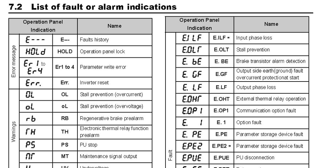
56 Display Screen Error Code Index FAULT CODE DRIVE DISPLAY DERSCRIPTION 0 - No fault 16 E.OC1 Overcurrent trip during acceleration 17 E.OC2 Overcurrent trip during constant speed 18 E.OC3 Overcurrent trip during deceleration or stop 32 E.OV1 Regenerative overvoltage trip during acceleration 33 E.OV2 Regenerative overvoltage trip during constant speed 34 E.OV3 Regenerative overvoltage trip during deceleration or stop 48 E.THT Inverter overload trip (electronic thermal relay function) 49 E.THM Motor overload trip (electronic thermal relay function) 64 E.FIN Fin overheat 82 E.ILF Input phase loss 96 E.OLT Stall prevention 112 E.BE Brake transistor alarm detection 128 E.GF Output side earth (ground) fault overcurrent at start 129 E.LF Output phase loss 144 E.OHT External thermal relay operation 145 E.PTC PTC thermistor operation 176 E.PE Parameter storage device fault (control circuit board) 177 E.PUE PU disconnection 178 E.RET Retry count excess 192 E.CPU CPU fault 196 E.CDO Output current detection value exceeded 197 E.IOH Inrush current limit circuit fault 199 E.AIE Analog input fault 201 E.SAF Safety circuit fault Rev 7
57 Prior to any repair work on the machine and its drives, secure the machine against unintentional powering on. Problem Possible cause Remedy Excessive Imbalance due to worn or Replace all worn or broken Vibration broken grinding tools. parts. Screws worked loose on the grinding disc. Unusual noises Defective bearing. Wrong tension of the V- belt. Defective motor bearing. Debris deposit on the coupling. Tighten the countersunk head screws on the grinding disc. Check the bearing on the axle drive shaft and replace if necessary. Check the tension of the V- belt; replace the V-belt if necessary. Reduced or no grinding performance Grinding tools have reached the maximum permissible wear. Inappropriate grinding tool for the application. Not enough tension on the V-belt. Change the motor. Clean the coupling. Replace the worn parts. Replace the grinding tools with appropriate tools for the surface to be treated. Re-tension the V-belt. Work on electrical equipment may only be undertaken by a skilled electrician or by a trained person under the supervision of an electrician, as well as in accordance with the local electrical engineering regulations. Rev 7
58 Prior to any repair work on the machine and its drives, secure the machine against unintentional powering on. Problem Possible cause Remedy Motor does not Missed phase Check the main power supply switch on and switch on again Replace Defective component defective component Motor triggers while running Motor protections switch triggered because of overload Motor has defect Reduce additional load Screen Goes Blank Lost Phase Check the motor Check for 3 legs power No voltage reading on Dis- Loose connection Check pin connectors on interface Rev 7
59 SASE MANUFACTURER S WARRANTY POLICY Included in this warranty are the following pieces of equipment: Planetary Diamond Grinders: PDG 8000, PDG 6000, PDG 5000, Edge Pro 180 Dust Extractors: Bull 1250, Bull 300, Bull 45 Our Commitment to our customer: SASE Company ( SASE ) equipment is warranted to be free of defects in workmanship and materials for a period of one (1) year from original date of purchase. In the event that you should have a claim SASE shall repair, replace or remedy the defective parts resulting from the faulty design, materials or workmanship. Note: This warranty is only valid for equipment either sold by SASE or by an authorized wholesaler or distributor. Limitations: Warranty does not apply to cosmetic damage, damage due to lightning, electrical surgmisuse, abuse, repair or alteration by other than factory service (unless service center was approved in writing by SASE), negligence, or improper or neglected maintenance as recommended by SASE. exempt from warranty. or down time as a result faulty design, materials or workmanship. Warranty coverage is valid once a warranty SASE. A $100 labor charge may be assessed on the items returned for warranty repair in which no fault is found. Freight charges and associated fees will then become the responsibility of the customer in such an instance. tation are not covered under warranty. Such carrier. Claims: In the unlikely event that you should experience a defect please contact your SASE representative or a SASE service technician by calling Please have all pertinent information readily available such as, invoice with date of purchase, model and serial number, and an explanation of the issue. SASE will respond immediately with a corrective action. Freight responsibility for approved warranty claims: If the piece of equipment was purchased within 90 days of warranty claim, SASE will arrange for ground freight and will assume all ground freight charges to send the customer the parts required or to send the equipment to an authorized SASE repair center. This includes inbound and outbound ground freight and all fees (duties, fuel surcharges) associated with the shipment. If the piece of equipment was purchased beyond 90 days and prior to one (1) year of warranty claim, SASE will cover 50% of all ground freight charges, including inbound and outbound freight and all fees (duties, fuel surcharges) associated with the shipment.
60 SASE PRODUCT & WARRANTY REGISTRATION WARRANTY IS VOID IF NOT RETURNED AND REGISTERED WITH SASE WITHIN 30 DAYS OF PURCHASE COMPANY NAME AND TITLE STREET ADDRESS CITY STATE ZIP COUNTRY PHONE DATE OF PURCHASE SERIAL NUMBER INVOICE NUMBER OF PURCHASE PDG 8000 PDG 6000 PDG 5000 EDGE PRO 180 SC8E SC10E SC12E BULL 1250 BULL 300 BULL 45 PLEASE FILL OUT IN FULL AND SUBMIT TO: SASE COMPANY 2475 STOCK CREEK BLVD ROCKFORD TN, FAX: QUESTIONS? CALL
 SASE Planetary Diamond Grinders PDG 4500 230 volt 50/60 HZ single phase 8464.20.")
61 Corporate Office th Ave South Kent, WA (P) (F) Certificate of Declaration and Conformity: (Applies to Europe only) SASE Planetary Diamond Grinders PDG volt 50/60 HZ single phase PDG volt 50/60 HZ three phase PDG volt 50/60 HZ three phase PDG volt 50/60 HZ three phase PDG volt 50/60 HZ three phase PDG volt 50/60 HZ three phase PDG volt 50/60 HZ three phase SASE Company hereby certifies that the above listed Planetary Diamond Grinders are classified within the following EU directives of conformity for CE markings: EU Machinery directive 2006/42/EC EU Low voltage directive 2006/95/EC EU Electromagnetic compatibility directive 2004/108/EC and further conform with the following EU Harmonized Standards: EN :2007 EN : A1:2009 EN :2007 EN :2007
Safety Instructions Introduction Transportation Storage Setup and Operation Changing of Diamonds...
 Table of Contents Safety Instructions... 2 Introduction... 4 Transportation... 4 Storage... 4 Setup and Operation... 5 Changing of Diamonds... 7 Determining Diamond Selection... 9 Final Assembly... 11
PDG V PLANETARY EDGER. SASE Company, Inc. Phone or Fax
 PDG 3000 460V PLANETARY EDGER SASE Company, Inc. Phone 800.522.2606 or Fax 877.762.0748 www.sasecompany.com Version 1.2 9/27/2017 Corporate Office Details 26423 79th Ave South Kent, WA 98032-7321 1.800.522.2606
PDG Manual. SASE Company, Inc. Phone or Fax
 PDG 9500+ Manual SASE Company, Inc. Phone 800.522.2606 or Fax 877.762.0748 www.sasecompany.com Version 5 Ser. #: 2300 + Date : 8/1/2018 Table of Contents Cover... 1 Letter from SASE Safety Instructions
PDG 5000 PROPANE MANUAL
 PDG 5000 PROPANE MANUAL SASE Company, Inc. 800.522.2606 www.sasecompany.com SAFETY WARNING: Operate in large open ventilated areas only. Must not be run indoors or enclosed areas. Introduction The SASE
PDG 5000 PROPANE MANUAL
 PDG 5000 PROPANE MANUAL SASE Company, Inc. 800.522.2606 www.sasecompany.com Version: 5K04R3 Serial: 2000-2500 4/27/2018 2 -.' ---... *SASE. Corporate Office 26423 79 th Ave South Kent, WA 98032-7321 1.800.522.2606
Table of Contents Cover 1 Letter from Owner 3 Table of Contents 5 Introduction 6 Diamond Tooling 7 Changing Diamonds 8 Personal Safety 9 Diamond
 Version 14 Ser #: 1300-1400 Date: 4/7/2016 Table of Contents Cover 1 Letter from Owner 3 Table of Contents 5 Introduction 6 Diamond Tooling 7 Changing Diamonds 8 Personal Safety 9 Diamond Tooling Quick
DUAL HEAD FLOOR GRINDER PARTS LIST MODEL CC200
 DUAL HEAD FLOOR GRINDER PARTS LIST MODEL CC00 September 0 Part #8000 Table of Contents Description Page No. Frame Assembly.. - Disc Assembly..... 6 Flange Assembly.. Engine Group, 0 HP HondaGas. 8 Gear
MODEL 83 Pail Handler
 MORSE MFG. CO., INC. 727 West Manlius Street P.O. Box 518 East Syracuse, NY 13057-0518 Phone: 315-437-8475 Fax: 315-437-1029 Email: service@morsemfgco.com Website: www.morsemfgco.com COPYRIGHT 2005 MORSE
VARIABLE SPEED WOOD LATHE
 MODEL MC1100B VARIABLE SPEED WOOD LATHE INSTRUCTION MANUAL Please read and fully understand the instructions in this manual before operation. Keep this manual safe for future reference. Version: 2015.02.02
CAUTION! This manual contains important information for the correct installation, operation and maintenance of the equipment described herein.
 CAUTION! This manual contains important information for the correct installation, operation and maintenance of the equipment described herein. All persons involved in such installation, operation, and
VARIABLE SPEED BECH LATHE
 VARIABLE SPEED BECH LATHE Instruction Manual Please read this instruction manual thoroughly and follow all directions carefully. 1 Important Safety Instructions READ ALL INSTRUCTIONS AND WATNINGS BEFORE
INSTRUCTION BOOKLET AND WARRANTY INFORMATION 6 BENCH GRINDER
 INSTRUCTION BOOKLET AND WARRANTY INFORMATION 6 BENCH GRINDER Part No.: SW1250 PLEASE READ CARE AND SAFETY INSTRUCTIONS BEFORE USE SPECIFICATIONS Part No.: SW1250 Input Voltage: 240V Frequency: 50Hz Rated
VARIABLE SPEED WOOD LATHE. Model DB900 INSTRUCTION MANUAL
 VARIABLE SPEED WOOD LATHE Model DB900 INSTRUCTION MANUAL 1007 TABLE OF CONTENTS SECTION...PAGE Technical data.. 1 General safety rules....1-3 Specific safety rules for wood lathe.....3 Electrical information.4
SECTION 7 - SUSPENSION
 For Arctic Cat Discount Parts Call 606-678-9623 or 606-561-4983 SECTION 7 - SUSPENSION TABLE OF CONTENTS Section Front and Rear Suspension Assembly Schematics... 7-2 Shock Absorbers... 7-4 Swing Arms (ACT
GENERAL OPERATIONAL PRECAUTIONS PRECAUTIONS ON USING CUT-OFF MACHINE
 GENERAL OPERATIONAL PRECAUTIONS WARNING! When using electric tools, basic safety precautions should always be followed to reduce the risk of fire, electric shock and personal injury, including the following.
DIAMOND MODEL CC1900 EARLY ENTRY CONCRETE SAW PARTS LIST P R O D U C T S. (March 2012) Part #
 Part #") DIAMOND P R O D U C T S EARLY ENTRY CONCRETE SAW PARTS LIST MODEL CC1900 (March 2012) Part #1801617 (Intentionally Blank) TABLE OF CONTENTS Description Page No. Frame Assembly....4-5 Engine Assembly......6
DIAMOND P R O D U C T S EARLY ENTRY CONCRETE SAW PARTS LIST MODEL CC1900 (March 2012) Part #1801617 (Intentionally Blank) TABLE OF CONTENTS Description Page No. Frame Assembly....4-5 Engine Assembly......6
EllisSaw.com. EllisSaw.com P.O. Box Verona, WI
 P.O. Box 9019 Verona, WI 9-019 GENERAL OPERATING & SAFETY INSTRUCTIONS * READ INSTRUCTIONS BEFORE USE * CAUTION: Disconnect power supply cord from power source when doing repair work or changing belt.
GENERAL OPERATIONAL PRECAUTIONS PRECAUTIONS ON USING DISC GRINDER
 GENERAL OPERATIONAL PRECAUTIONS WARNING! When using electric tools, basic safety precautions should always be followed to reduce the risk of fire, electric shock and personal injury, including the following.
ATBG280/6 Bench Grinder Bench Grinder ATBG280/6 230V-50Hz 280 Watt 150mm x 25mm Wheel size
 Bench Grinder ATBG280/6 230V-50Hz 280 Watt 150mm x 25mm Wheel size SPECIFICATIONS Model Number : ATBG280/6 Nominal Voltage Power Consumption No load speed Wheel size Weight 230Volt 50Hz 280 Watts 2880
10" Wet Tile Cutting Saw
 8035735 10" Wet Tile Cutting Saw Owner s Manual Read and understand all instructions before operation. Keep this manual for future reference pg. 2 SPECIFICATIONS ITEM DESCRIPTION Overall Dimensions (saw
1300-lb Furniture and Crate Movers
 1300-lb Furniture and Crate Movers Owner s Manual WARNING: Read carefully and understand all ASSEMBLY AND OPERATION INSTRUCTIONS before operating. Failure to follow the safety rules and other basic safety
MODEL M1023 QUICK CHANGE COLLET ATTACHMENT INSTRUCTION MANUAL. Phone: On-Line Technical Support:
 MODEL M1023 QUICK CHANGE COLLET ATTACHMENT INSTRUCTION MANUAL Phone: 1-360-734-3482 On-Line Technical Support: tech-support@shopfox.biz #6727BL COPYRIGHT JANUARY, 2005 BY WOODSTOCK INTERNATIONAL, INC.
HOLE CUTTER SHARPENER ASSEMBLY & SERVICE MANUAL
 HOLE CUTTER SHARPENER ASSEMBLY & SERVICE MANUAL WARNING You must thoroughly read and understand this manual before operating the equipment, paying particular attention to the Warning & Safety instructions.
24 GA. PITTS ROLLFORMER
 1 TIN KNOCKER 24 GA. PITTS ROLLFORMER INSTRUCTIONS & PARTS DIAGRAM Shown with Stand and Optional Flanging Attachment Rev. 092606 TAAG MACHINERY CO. (Master Distributor) 1257-B Activity Dr. Vista, CA 92081
STEEL BLASTER CABINET FLOOR MODEL
 STEEL BLASTER CABINET FLOOR MODEL 39170 ASSEMBLY & OPERATING INSTRUCTIONS 3491 Mission Oaks Blvd., Camarillo, CA 93011 Visit our Web Site at www.harborfreight.com Copyright 1998 by Harbor Freight Tools.
TABLE OF CONTENTS DESCRIPTION. Safety Instructions Assembly Operation... 7
 TABLE OF CONTENTS DESCRIPTION PAGE Warranty... 1 Safety Instructions... 2 Assembly... 3 Operation... 7 #360 Grain Cleaner Drawings... 8 #360 Grain Cleaner Parts List... 10 Utility Auger Option Drawing...
Angle Grinder. Model Visit our website at:
 Angle Grinder Safety Guard Model 45921 Installation Instructions Note: Cutting Blade and Angle Grinder sold separately. Visit our website at: http://www.harborfreight.com Read this material before using
3/8 Butterfly Air Impact Wrench
 3/8 Butterfly Air Impact Wrench 37730 ASSEMBLY AND OPERATING INSTRUCTIONS 3491 Mission Oaks Blvd., Camarillo, CA 93011 Visit our Web site at http://www.harborfreight.com Copyright 2004 by Harbor Freight
SAVE THIS FOR FUTURE REFERENCE THIS PRODUCT IS FOR PROFESSIONAL LABORATORY USE ONLY USER'S MANUAL
 DENTAL, INC. TECHNICAL BULLETIN G801-022510 5860 FLYNN CREEK ROAD READ ALL INSTRUCTIONS P.O. BOX 106 BEFORE PROCEEDING COMPTCHE, CALIFORNIA, U.S.A. 95427-0106 SAVE THIS FOR FUTURE REFERENCE www.wellsdental.com
Angle Grinder MODEL 9553B MODEL 9555B
 ENGLISH Angle Grinder MODEL 9553B MODEL 9555B 006649 DOUBLE INSULATION I N S T R U C T I O N M A N U A L WARNING: For your personal safety, READ and UNDERSTAND before using. SAVE THESE INSTRUCTIONS FOR
8 Buffer. Set up and Operating Instructions. (Buffing Wheels Not Included) Distributed exclusively by Harbor Freight Tools.
 Distributed exclusively by Harbor Freight Tools.") 8 Buffer 40668 Set up and Operating Instructions (Buffing Wheels Not Included) Distributed exclusively by Harbor Freight Tools. 3491 Mission Oaks Blvd., Camarillo, CA 93011 Visit our website at: http://www.harborfreight.com
8 Buffer 40668 Set up and Operating Instructions (Buffing Wheels Not Included) Distributed exclusively by Harbor Freight Tools. 3491 Mission Oaks Blvd., Camarillo, CA 93011 Visit our website at: http://www.harborfreight.com
 GENERAL OPERATIONAL PRECAUTIONS WARNING! When using electric tools, basic safety precautions should always be followed to reduce the risk of fire, electric shock and personal injury, including the following.
INSTRUCTION BOOK AND PARTS LIST
 Rag Cutter MODEL WE WARNING This machine is equipped with a very sharp knife. Keep hands, arms, and hair away from the knife area at all times. Misuse of this machine or failure to follow all safety instructions
Specifications. Important Safety Information
 Specifications Tire Rim Capacity 4 to 12 Rim Height 16 (2) Bead Breaker Handles 21 Long Includes Aluminum Centering Cone (2) Nylon Spacers Important Safety Information 1. Do not exceed max. tire capacity.
H8508 Impact Wrench SERVICE MANUAL. Model (Serial Code FWN) Model (Serial Code FWP)
 Model (Serial Code FWP)") SERVICE MANUAL H8508 Impact Wrench Model 48755 (Serial Code FWN) Model 48760 (Serial Code FWP) Read and understand all of the instructions and safety information in this manual before operating or servicing
SERVICE MANUAL H8508 Impact Wrench Model 48755 (Serial Code FWN) Model 48760 (Serial Code FWP) Read and understand all of the instructions and safety information in this manual before operating or servicing
26 GARDEN CART ASSEMBLY & OPERATING INSTRUCTIONS. Rev 07/03
 GARDEN CART 304 ASSEMBLY & OPERATING INSTRUCTIONS 3 Rev 07/03 THANK YOU for choosing a HARBOR FREIGHT TOOLS product. For future reference, please complete the owner s record below: Model Serial No. Purchase
Trautman Carvers. Product Manual
 Trautman Carvers Product Manual Contents Product Specifications.... 4 Operating Precautions.... 6 Floor Carver Use.... 7 Floor Carver Diagram.... 10 Trautman Motor Lift Assist.... 11 Use of the Lift Assist....
18 GAUGE ELECTRIC METAL SHEAR
 241-9895 18 GAUGE ELECTRIC METAL SHEAR Operator s Manual SAVE THIS MANUAL You will need this manual for safety instructions, operating procedures and warranty. Put it and the original sales receipt in
Mortising Attachment
 Mortising Attachment Owner s Manual WARNING: Read carefully and understand all ASSEMBLY AND OPERATION INSTRUCTIONS before operating. Failure to follow the safety rules and other basic safety precautions
Power Planer 1900B/N1900B/1902
 Power Planer 1900B N1900B 1902 SPECIFICATIONS Model 1900B/N1900B/1902 Planing width... 82 mm Planing depth... 1 mm Shiplapping depth... 9 mm No load speed (min -1 )...16,000 Overall length... 290 mm Net
Owner s Manual & Safety Instructions
 Owner s Manual & Safety Instructions Save This Manual Keep this manual for the safety warnings and precautions, assembly, operating, inspection, maintenance and cleaning procedures. Write the product s
Instructions for Stone Cutting Machine
 Technical data Kg. Instructions for Stone Cutting Machine SCM600 3HP 2800rpm IP55 SCM800 3HP 2800rpm IP55 SCM1000 2800rpm IP55 SCM1200 2800rpm IP55 L=600 B=85(165) L=800 B=85(175) 500x510 0 or 45 600lt/h
PLATE JOINER 4 INCH. ASSEMBLY and OPERATING INSTRUCTIONS. Distributed Exclusively by Harbor Freight Tools
 PLATE JOINER 4 INCH 38437 ASSEMBLY and OPERATING INSTRUCTIONS Distributed Exclusively by Harbor Freight Tools 3491 Mission Oaks Blvd., Camarillo, CA 93011 Copyright 1998 by Harbor Freight Tools. All rights
Item# " VARIABLE SPEED BENCH GRINDER USER'S MANUAL
 Power Tools Item# 33309 3" VARIABLE SPEED BENCH GRINDER USER'S MANUAL Read carefully and understand RULES FOR SAFE OPERATION and instructions before operating. Failure to follow the safety rules and other
Tapping Screw (W/Flange) 46 Cord Armor 47 Tube (D) 48 Cord. 45 Cord Clip. Tapping Screw (W/Flange) 10 Gear Cover Ass'y. 12 Socket (B) Ass'y
 46 Cord Armor 47 Tube (D) 48 Cord. 45 Cord Clip. Tapping Screw (W/Flange) 10 Gear Cover Ass'y. 12 Socket (B) Ass'y") W8VB The exploded assembly drawing should be used only for authoized service center. W8VB Item No. Part time 1 Magnetic Hex. Socket 2 Sub Stopper 3 O-Ring (S-16) 4 Locator (A) 5 Lock Sleeve (A) 6 O-Ring
W8VB The exploded assembly drawing should be used only for authoized service center. W8VB Item No. Part time 1 Magnetic Hex. Socket 2 Sub Stopper 3 O-Ring (S-16) 4 Locator (A) 5 Lock Sleeve (A) 6 O-Ring
ROUND BENDING MACHINE Model: RBM30
 ROUND BENDING MACHINE Model: RBM30 Operation Manual SAVE THIS MANUAL:You will need the manual for the safety warnings and precautions, assembly instructions, operating and maintenance procedures, parts
WALK-BEHIND SPREADER 50 LB. CAPACITY Model 99623
 WALK-BEHIND SPREADER 50 LB. CAPACITY Model 99623 Assembly, Operating, and Maintenance Instructions Diagrams within this manual may not be drawn proportionally. Due to continuing improvements, actual product
1/4 Sheet Palm Sander
 OWNER S MANUAL Model Number: PS160CA-3 1/4 Sheet Palm Sander TM Registration Card Inside CAUTION! To reduce the risk of fire, electric shock and personal injury, read and understand the owner s manual
Electric Chainsaw Sharpener
 FPP CHAINSS Electric Chainsaw Sharpener Instruction Manual For your own safety, please ensure you have read these instructions before use and have fully understood all the safety guidelines. Specifications
C a r r i a g e A s s e m b l y R e p l a c e m e n t
 E1 TF-CR C a r r i a g e A s s e m b l y R e p l a c e m e n t October 2007 Software Version 5.0 and higher IMPORTANT! TigerStop must be enabled with a code that must be obtained from TigerStop Customer
30AUTO Speed Lathe Manual
 30AUTO Speed Lathe Manual Standard Features 3/4 HP Motor Air-Collet Closure 1800 RPM, Single Speed Electric Brake Cast Housing 5C Collets 3 Phase / 240 Volts DESCRIPTION: The Crozier Model 30AUTO Automotive
TABLE OF CONTENTS DESCRIPTION. Safety Instructions Assembly Operation... 7
 TABLE OF CONTENTS DESCRIPTION PAGE Warranty... 1 Safety Instructions... 2 Assembly... 3 Operation... 7 #360 Grain Cleaner Drawings... 8 #360 Grain Cleaner Parts List... 10 Utility Auger Option Drawing...
Gared Pro-S Portable Backstop
 Models: 9616 & 9618 Installation, Operation and Maintenance Instructions Please read all instructions before attempting installation or operation of these units SAVE THESE INSTRUCTIONS FOR FUTURE USE PUBLICATION
400 SERIES GRINDER PUMPS 41502, 42202,43302, AND MODELS
 Section: MOYNO 500 PUMPS Page: 1 of 6 Date: March 1, 1998 SERVICE MANUAL MOYNO 500 PUMPS 400 SERIES GRINDER PUMPS 41502, 42202,43302, AND 44402 MODELS DESIGN FEATURES Housing: Cast iron Pump Rotor: Chrome
Operating Manual 6 Industrial Bench Grinder ATBG280/
 Operating Manual 6 Industrial Bench Grinder ATBG280/6 804531 40 Year Australian Heritage The reputable name in bench grinders for 40 years Protect yourself and others by observing all safety information,
ATV CULTIVATOR OWNER S MANUAL
 ATV CULTIVATOR OWNER S MANUAL WARNING: Read carefully and understand all ASSEMBLY AND OPERATION INSTRUCTIONS before operating. Failure to follow the safety rules and other basic safety precautions may
Model W1854 (For Machines Mfd. Since 02/18) PARTS. Main Breakdown 42-1 PARTS -46-
 PARTS. Main Breakdown 42-1 PARTS -46-") 3 144 1 143 119 1 4-1 14 140 13 4 1 1 4 14 11 7 108 134 131 13 14 100 1 8 16 9 80 93 40 14 146 39 Main Breakdown 133 117 130 10 3 19 3 11 10 9 38 9 7 6 4 13 7 134 16 138 141 Model W184 (For Machines Mfd.
3 144 1 143 119 1 4-1 14 140 13 4 1 1 4 14 11 7 108 134 131 13 14 100 1 8 16 9 80 93 40 14 146 39 Main Breakdown 133 117 130 10 3 19 3 11 10 9 38 9 7 6 4 13 7 134 16 138 141 Model W184 (For Machines Mfd.
CONCRETE SAW PARTS LIST
 CONCRETE SAW PARTS LIST MODEL CCXL-EE December 01 Part # 1 Intentionally Blank Table of Contents Description Page No. Frame Assembly... Carriage Assembly Motor Assembly.... Blade Shaft Assembly... Spring
GENERAL OPERATIONAL PRECAUTIONS
 GENERAL OPERATIONAL PRECAUTIONS WARNING! When using electric tools, basic safety precautions should always be followed to reduce the risk of fire, electric shock and personal injury, including the following.
TRAKFAST REPAIR MANUAL DANGER TOOL DISASSEMBLY ALWAYS TAKE THE FOLLOWING PRECAUTIONS BEFORE ANY SERVICE OR ROUTING MAINTENANCE IS PERFORMED:
 DANGER ALWAYS TAKE THE FOLLOWING PRECAUTIONS BEFORE ANY SERVICE OR ROUTING MAINTENANCE IS PERFORMED: REMOVE FASTENERS REMOVE FUEL CELL REMOVE BATTERY REMOVE THE MAGAZINE ASSEMBLY Loosen and remove knob
SMALL GAUGE NIBBLER ASSEMBLY & OPERATING INSTRUCTIONS Mission Oaks Blvd., Camarillo, CA Visit our Web Site at
 SMALL GAUGE NIBBLER 91739 ASSEMBLY & OPERATING INSTRUCTIONS 3491 Mission Oaks Blvd., Camarillo, CA 93011 Visit our Web Site at www.harborfreight.com Copyright 2004 by Harbor Freight Tools. All rights reserved.
Core EZ. Operating Manual. Toll Free B East Broadway Avenue Tampa, FL 33619
 Operating Manual 3702 West Central Avenue Santa Ana, CA 92704 Toll Free 1-866-987-7297 11 High Street Suffield, CT 06078 www.ussaws.com 8004B East Broadway Avenue Tampa, FL 33619 Introduction This manual
Record the serial number and date of purchase on your parts list for future reference.
 Jointer Model: 0-0 Parts List Record the serial number and date of purchase on your parts list for future reference. Serial number: Date of purchase: Part # 0-0PL For more information: www.rikontools.com
STRINGING MACHINE OWNER'S MANUAL. Copyright 1998 GAMMA Sports - All Rights Reserved
 6002 STRINGING MACHINE OWNER'S MANUAL Issue 3 - June 20, 1998 Copyright 1998 GAMMA Sports - All Rights Reserved 6002 OWNER'S MANUAL TABLE OF CONTENTS PAGE 1... WARRANTY PAGE 2... FEATURES PAGE 3... ASSEMBLY
The DeltaGrip System. Safety and Operating Instructions. Trigger. Air Supply Connection. Handle Assembly. Air Line Assembly.
 The DeltaGrip System Safety and Operating Instructions Trigger Air Supply Connection Handle Assembly Air Line Assembly Punch Die Pneumatic Diaphragm Assembly Shackle, Pin & Jam Nut Jaw Frame Shoulder Screw
Tube Facing Tool.
 www.swagelok.com Tube Facing Tool This manual contains important information for the safe and effective operation of the Swagelok TF72 series tube facing tool. Users should read and understand its contents
Model ADJUSTABLE ROLLER STAND WITH THREE-LEG SUPPORT
 ADJUSTABLE ROLLER STAND WITH THREE-LEG SUPPORT Model 46086 ASSEMBLY and Operating Instructions Visit our website at: http://www.harborfreight.com Read this material before using this product. Failure to
ARROW SAW PRECISE CUT 8000 RPM WITH DUST COLLECTING ATTACHMENT INSTRUCTION BOOK MODEL NO
 ATTENTION If any components of this unit are broken or the unit does not operate properly, please contact Cabela s Customer Service. Retail Store Purchases: 1-800-905-2731 (U.S. & Canada) Catalog and Internet
Finger Jointer. Operating and Safety Instructions FJA300
 Finger Jointer FJA300 Operating and Safety Instructions www.tritontools.com Thank you for purchasing this Triton tool. These instructions contain information necessary for safe and effective operation
Engineering Data Single Reduction Parts List Item # Description Basic Single Reduction Unit 1. Gear Housing 2. Pipe Plug 3. Vent Plug 4. Splash Guard
 Engineering Data Single Reduction Parts List Item # Description Basic Single Reduction Unit 1. Gear Housing 2. Pipe Plug 3. Vent Plug 4. Splash Guard 5. Input Cover 6. O-Ring 7. Hex Head Cap Screw 8. Input
GP ONE SPLIT DECK 9/4/2012 COPYRIGHT 6/10/10 ALL RIGHTS RESERVED
 GP ONE SPLIT DECK PAGE G & P ONE GRINER SPLIT DECK SUB ASSEMBLY PARTS BREAK DOWN 4 2 24 20 2 6 0 36 24 7 27 2 2 25 3 32 2 24 28 24 8 7 24 5 2 25 2 20 2 4 3 2 34 5 26 22 2 27 35 22 3 30 6 9 29 8 29 2 9
12mm (Max) 6mm (Max) 82mm (Max) 12mm (Max) 6mm (Max)
 6mm (Max) 82mm (Max) 12mm (Max) 6mm (Max)") 1 1 2 2 3 3 82mm (Max) 12mm (Max) 12mm (Max) 6mm (Max) 4 4 5 6 8 6mm (Max) 0.5 0mm 1 5 6 7 7 8 9 9 A = B 10 11 12 D B 1 13 14 15 0 C A D E 16 17 18 F G D B N H J G I K 19 A 20 G L 21 C K 1mm L M 1mm 22
1 1 2 2 3 3 82mm (Max) 12mm (Max) 12mm (Max) 6mm (Max) 4 4 5 6 8 6mm (Max) 0.5 0mm 1 5 6 7 7 8 9 9 A = B 10 11 12 D B 1 13 14 15 0 C A D E 16 17 18 F G D B N H J G I K 19 A 20 G L 21 C K 1mm L M 1mm 22
Powermatic Model 31A Combination Belt-Disk Sander
 OPERATING PROCEDURE FOR: Powermatic Model 31A Combination Belt-Disk Sander INTRODUCTION: The combination belt-disk sander is used to sand the edges of boards. It can be used to smooth the edge or to remove
MODEL W1.0X305A(12 ) MODEL W1.0X610A(24 ) HAND BENDING BRAKE ASSEMBLY&OPERATING INSTRUCTION
 MODEL W1.0X610A(24 ) HAND BENDING BRAKE ASSEMBLY&OPERATING INSTRUCTION") MODEL W1.0X305A(12 ) MODEL W1.0X610A(24 ) HAND BENDING BRAKE ASSEMBLY&OPERATING INSTRUCTION 1 SAVE THIS MANUAL You will need the manual for the safety warning and precautions, assembly instructions, operating
MODEL W1.0X305A(12 ) MODEL W1.0X610A(24 ) HAND BENDING BRAKE ASSEMBLY&OPERATING INSTRUCTION 1 SAVE THIS MANUAL You will need the manual for the safety warning and precautions, assembly instructions, operating
ITEM Pipe Thread Kit (10 Piece Set - 7 Dies) Assembly and Operating Instructions
 Assembly and Operating Instructions") ITEM 94098 Pipe Thread Kit (10 Piece Set - 7 Dies) Assembly and Operating Instructions 3491 Mission Oaks Blvd., Camarillo, CA 93011 Copyright 2006 by Harbor Freight Tools. All rights reserved. No portion
ITEM 94098 Pipe Thread Kit (10 Piece Set - 7 Dies) Assembly and Operating Instructions 3491 Mission Oaks Blvd., Camarillo, CA 93011 Copyright 2006 by Harbor Freight Tools. All rights reserved. No portion
HYDRAULIC CONTROL DETAILS PARTS LIST
 Always give model number, serial number and part number when ordering repair parts. HYDRAULIC CONTROL DETAILS PARTS LIST REF NO. PART NUMBER DESCRIPTION 1 101939 Hydraulic Tank 2 101940 Hydraulic Tank
30 Bending Brake. Model Assembly and Operating Instructions. Distributed exclusively by Harbor Freight Tools.
 30 Bending Brake Model 41311 Assembly and Operating Instructions Distributed exclusively by Harbor Freight Tools. 3491 Mission Oaks Blvd., Camarillo, CA 93011 Copyright 1999 by Harbor Freight Tools. All
M-5 PRO CORE BORE PARTS LIST DRILLING MACHINE. (March 2017) Part #
 Part #") M- PRO CORE BORE DRILLING MACHINE PARTS LIST (March 07) Part #809 Table of Contents Description Page No. Carriage Assembly....... - Combo Base Assembly....... - 7 Anchor Base Assembly........8 Anchor
M- PRO CORE BORE DRILLING MACHINE PARTS LIST (March 07) Part #809 Table of Contents Description Page No. Carriage Assembly....... - Combo Base Assembly....... - 7 Anchor Base Assembly........8 Anchor
Main Drive Components
 Pipe and Bolt Threading Machine Main Drive Components 0 0 Rear Centering Head Centering Jaw Set Spiral Pins () 00 Centering Scroll Retaining Ring 0 Rear Bearing 0 Oil Ball Valve () # - x / Screw Motor
MODELS: CC3730TE / CC3740TE
 DIAMOND P R O D U C T S CONCRETE SAW PARTS LIST MODELS: CC0TE / CC0TE February 00 Part #00 Table of Contents Pictorial Page Index....., Belt Guard Assembly... Controls Legend....... Belt Tensioner Assembly....
Please read and understand the OnBoard Timpani Cart Owner s Manual before using the Timpani Cart.
 Assembly and Owner s Manual OnBoard Timpani Cart Performance Position Towing Position CONTENTS Important User Information...........................2 General......................................2 Manufacturer.................................2
SERVICE PARTS LIST PAGE 1 OF 6 BASE ASSEMBLY SPECIFY CATALOG NO. AND SERIAL NO. WHEN ORDERING PARTS 12" DUAL BEVEL COMPOUND MITER SAW B27B
 PAGE 1 OF 6 BASE ASSEMBLY 00 0 EXAMPLE: Component Parts (Small #) Are Included When Ordering The Assembly (Large #). SPECIFY CATALOG NO. AND NO. WHEN ORDERING PARTS = Part number change from previous service
REPAIR INSTRUCTIONS. Cat. No Cat. No MILWAUKEE ELECTRIC TOOL CORPORATION. SDS Max Demolition Hammer. SDS Max Rotary Hammer
 Cat. No. 9-0 SDS Max Demolition Hammer Cat. No. -0 SDS Max Rotary Hammer MILWAUKEE ELECTRIC TOOL CORPORATION W. LISBON ROAD BROOKFIELD, WISCONSIN 00-0 8-9-0 d 000 8-9-0 d Special Tools Require Forcing
JARVIS. Model BR-3 Blade Reconditioner ... EQUIPMENT TABLE OF
 - Model BR-3 Blade Reconditioner EQUIPMENT SELECTION.......... Ordering No. TABLE OF CONTENTS............................ Page Model BR-3 (100 mm Blade) 115V/60Hz............ 4011003 220V/50Hz............
Walk-Behind Lawn Mowers
 Walk-Behind Lawn Mowers Parts Manual Models 2 - PRO21SCH 12 - LM21 1 - LM21S 1 - LM21SW 1 - LM21S 11 - PRO21SCH 0 - LM21SW - LM21S - LM21SW 5 - LM21S - LM21SW 0700 /0 Printed in USA THE MANUAL Before you
DUST COLLECTOR 70 GALLON, 2 HP
 DUST COLLECTOR 70 GALLON, 2 HP Model 45378 ASSEMBLY AND OPERATING INSTRUCTIONS 3491 Mission Oaks Blvd., Camarillo, CA 93011 Visit our Web site at http://www.harborfreight.com Copyright 2001 by Harbor Freight
CONCRETE SAW PARTS LIST
 CONCRETE SAW PARTS LIST MODEL CC00XL ELECTRIC & HYDRAULIC UNITS August, 0 Part # 0 Table of Contents Common Parts.. Front Axle Assembly... Rear Axle Assembly... Transmission Assembly... Blade Shaft Assembly
HEIGHT ADJUSTABLE WORKBENCH
 HEIGHT ADJUSTABLE WORKBENCH Model 91 ASSEMBLY and Operating Instructions Visit our website at: http://www.harborfreight.com Read this material before using this product. Failure to do so can result in
Sink BULL INSTRUCTION MANUAL. with Rapid Z -CUT & Rapid Z -DRUM
 Sink BULL with Rapid Z -CUT & Rapid Z -DRUM INSTRUCTION MANUAL Please read this instruction manual thoroughly to ensure safety and the correct use of this tool. Keep this manual in a place where operators
Impact Wrench. 19 mm (3/4 ) MODEL 6906
 MODEL 6906") Impact Wrench 9 mm (3/4 ) MODEL 6906 002290 DOUBLE INSULATION I N S T R U C T I O N M A N U A L WARNING: For your personal safety, READ and UNDERSTAND before using. SAVE THESE INSTRUCTIONS FOR FUTURE REFERENCE.
Impact Wrench 9 mm (3/4 ) MODEL 6906 002290 DOUBLE INSULATION I N S T R U C T I O N M A N U A L WARNING: For your personal safety, READ and UNDERSTAND before using. SAVE THESE INSTRUCTIONS FOR FUTURE REFERENCE.
DIAMOND CONCRETE SAW PARTS LIST MODEL CC1113-XL P R O D U C T S. June Part #
 DIAMOND P R O D U C T S CONCRETE SAW PARTS LIST MODEL CC1113-XL June 013 Part #10 TABLE OF CONTENTS Description Page No. Saw Assembly (Normal Cut).... - Saw Assembly (Up-Cut)...... - Gas Engine Assembly......
INSTRUCTION MANUAL. 125 mm (5 ) MODEL 9005B 125 mm (5 ) MODEL 9005BZ. DOUBLE I N S U LATlO N SPEC IF I CAT I 0 N S
 MODEL 9005B 125 mm (5 ) MODEL 9005BZ. DOUBLE I N S U LATlO N SPEC IF I CAT I 0 N S") 25 mm (5 ) MODEL 9005B 25 mm (5 ) MODEL 9005BZ INSTRUCTION MANUAL DOUBLE I N S U LATlO N SPEC IF I CAT I 0 N S No load speed (RPM) 0,000lmin. AMPS Overall Net Power Spindle (5 V) length weight supply cord
25 mm (5 ) MODEL 9005B 25 mm (5 ) MODEL 9005BZ INSTRUCTION MANUAL DOUBLE I N S U LATlO N SPEC IF I CAT I 0 N S No load speed (RPM) 0,000lmin. AMPS Overall Net Power Spindle (5 V) length weight supply cord
LPK1550 Hydraulic Crimping Tool 15-ton
 SERVICE MANUAL LPK1550 Hydraulic Crimping Tool 15-ton Serial Code FYF Read and understand all of the instructions and safety information in this manual before operating or servicing this tool. Register
Variable Speed Cast Iron Midi Wood Lathe
 01936 Variable Speed Cast Iron Midi Wood Lathe Please read and fully understand the instructions in this manual before operation. Keep this manual safe for future reference. 1 Technical Data Input voltage
HAND HELD SAW W MILL
 HAND HELD SAW W MILL 92247 ASSEMBLY AND OPERATING INSTRUCTIONS 3491 Mission Oaks Blvd., Camarillo, CA 93011 Visit our Web site at http://www.harborfreight.com Copyright 2004 by Harbor Freight Tools. All
SECTION 9: PARTS. G7947 Stand & Table Breakdown 4V2
 SECTION 9: PARTS G7947 Stand & Table Breakdown 19 15 21 18 16 17 112 5 113 3 14 8 7 6 6-1 13 4V2 12 116 11 9 10 2 114 115 1 We do our best to stock replacement parts when possible, but we cannot guarantee
10 Ton Pull Back Ram
 10 Ton Pull Back Ram Model 97207 Set up And Operating Instructions Diagrams within this manual may not be drawn proportionally. Due to continuing improvements, actual product may differ slightly from the
12 Slip Roll. Model Assembly & Operating Instructions
 12 Slip Roll Model 36698 Assembly & Operating Instructions Diagrams within this manual may not be drawn proportionally. Due to continuing improvements, actual product may differ slightly from the product
BUY PARTS ONLINE AT GRIZZLY.COM!
 SECTION 9: PARTS Tables, Fence & Cutterhead 28 29 26 27 25 23 23 22 24 22 35 37 36 38 16 15 17 18 39 11 14 19 20 21 13 12 6 7 8 9 10 1 2 5 49 3 4 3 31 30 6 7 94 93 95 40 96 43 42 44 45 46 47 48 55 55-4
TABLE OF CONTENTS MODEL 8750/8800 OCL
 TABLE OF CONTENTS MODEL 8750/8800 OCL Warranty Registration...2 Warranty...3 Vehicle Preparation...4 Attaching the Lathe using Universal Plates (8750)...5 Threaded Plates (RED)...6 Unthreaded Plates (BLUE)...7