PDG 5000 PROPANE MANUAL
|
|
|
- Silvia Harmon
- 5 years ago
- Views:
Transcription


1 PDG 5000 PROPANE MANUAL SASE Company, Inc
2 SAFETY WARNING: Operate in large open ventilated areas only. Must not be run indoors or enclosed areas. Introduction The SASE PLANETARY DIAMOND GRINDERS are designed for wet or dry grinding of marble, terrazzo, granite and concrete. Their applications range from rough grinding through to a polished finish. It is extremely important all users be familiar with the contents of SASE manuals before commencing operation of either machine. Failure to do so may result in damage to machinery or expose operator to unnecessary dangers. IMPORTANT Only staff that has received the necessary training, both practically and theoretically concerning their usage should operate the machinery. Hazards While, this machine is easy to use and has been used safely for many years, there are risks involved in operating any large propane machinery. Toxic Emission Exposure Fire Relate Incidents Mechanical action of moving and hot machine parts Toxic Emission Exposure The major toxic gasses created when spent propane is exhausted are: Carbon monoxide (CO) - Over exposure to carbon monoxide results in brain damage, or death. Oxides of nitrogen (NOx) Can damage lung tissue, aggravates respiratory diseases. Hydrocarbons (HC) Can damage lungs. We have included a sensor to test the air around the machine to limit exposure to toxic levels of emissions. Without proper ventilation, this sensor will shut down the machine after 30 seconds of use. Fire Relate Incidents The fire related incidents are few, because of strict fire safety prevention laws, regulations, devices, and practices. Some common causes of fire related hazards. Over fill If the tank is too full, and the pressure is vented indoors, that gas can start a fire, or be trapped dangerously in a room. Improper storage The storage location must be safe from extreme temperature, but also safe from theft, and tampering. Uneducated users The end user that does not understand the danger of improper use can cause unthinkable damage. Mechanical Action of Moving and Hot Machine Parts Several parts of this machine are understood to be dangerous. The front of the machine has a grill indicating it is HOT, this is an understatement. The muffler can reach nearly 1000F Degrees after use, and air venting from the motor side, can reach 800F to 1000F degrees as well. The handle is heavy. Failure to lock the handle in place can result in operator injury. During operation, the entire machine has a force of its own. If you lose control of the machine, it will walk away without you. The operator has to maintain control of the machine while it is on the ground. The machine moving freely can damage finished floor sections, or wall sections. Not to mention anyone caught by the grind head would be injured. Preventative Maintenance Preventing the hazard is the best case scenario. Preventative Maintenance (PM) is the responsibility of the operator. Check and clean air filter regularly Check Oil and adjust level as needed Keep a Log Book for all service done. Check fuel cylinder for overfill before taking them into a building Be SURE that adequate ventilation is in use. Properly store propane fuel cylinders and machines. Be aware of changes in operation, smell, noise, etc. while operating Report to management ANY safety concerns. Follow manufacturer recommendations for all motor maintenance. Propane Cylinder The cylinder used is classified as a DOT 4E240 cylinder. The service pressure the cylinder is designed for is at 20 PSI. The cylinder has a pressure relief if it reaches an excess of 300 PSI. If the tank is overfilled, this pressure relief will become active once the tank comes up to room temperature. Pressure relief is highly flammable! Never store the propane tank on the machine. Follow local and national regulation when using, storing and filling propane. In the case of pressure relief catching fire, it is necessary to cool the cylinder. Use non-flammable cooling liquid, or a fire extinguisher, to lower the temperature of the cylinder. The flow of gas should stop, when the cylinder is cooled. Shutting off the flow of gas should extinguish the fire the gas was fueling. Propane cylinders are above the capacity for storage in a place frequented by the public. So, storage on site at a grocery store would be against national fire safety code. NFPA 58 chapters 5 and 8 Storage The machine should always be stored in a cool, dry place when not in use. Do not store the machine with propane attached. The propane cylinder has to be stored in accordance with local and national regulation. Do not overlook the danger of propane fire or explosion! The Grind Head has a rotation and a counter rotation, keep body parts clear of the moving grinder head.


3 Operation Break-Down The machine can be divided into two main parts. 1. Chassis/Frame section This comprises the handle bars, body panels, Propane tank, Steel frame and wheels. 2. Head this comprises the motor, cover, grinding/satellite/ planetary heads and internal components The machine has been manufactured to allow movement between the chassis and head via the connection point. This movement is important during the grinding process as it creates a floating effect for the head. The floating gives the head a self leveling effect, negating the need to adjust the height of the head as the machine passes over floor areas with different slopes or undulations. Control Panel The operator controls consist of a number of toggles and switches, giving 4 separate controls. Ignition Turn to START until motor starts, leave in ON until finished. Turn to OFF, for motor stop. Speed Control The motor is connected to a throttle cable for speed control. Twist to lock/unlock, Pull for fast, push for slow. Clutch Engage/disengage the drum rotation NEVER ENGAGE/DISENGAGE CLUTCH ABOVE 2000 RPM! Set-Up Position the grinder in the working area. Make sure there are diamonds underneath the machine, and that the head locks are tight. IMPORTANT Planetary head and grinding heads are set to turn in opposite directions of each other.(as shown in this depiction) Machine Power-Up Connect battery harness & propane tank. Turn Key to START position for a moment Turn Key to ON position When using the machine, each grinding head must always have the same diamond type and number of diamonds as the other heads. Each diamond must also be the same height as the next. The Rubber skirt must be adjusted so that a good seal is established, between the floor and the drum. When setting the height of the handle, the operator is the guide. The comfort of the operator during grinding is key. The handlebar should rest right at the operator s hip bone. When the machine is running, there will be a grinding force to one side that can be felt through the handlebars. Use the hip to resist this force instead of the arms. Transportation When transporting, it is important to ensure the machinery is properly secured at all times to eliminate bouncing. Ensure the chassis or frame section of the machine is secured down at all times when in transit. The machine should always be transported under cover limiting the exposed to natural elements in particular rain and snow. The machine should not be lifted by handle, motor, chassis or other parts. Transportation of the machine is best done on a pallet/skid to which the machine must be firmly secured. Do not attempt to slide the tines/forks from a fork lift under grinding heads unless on a pallet/skid. Failure to do so can cause extreme damage to grinding heads of machine and internal parts. Drum Rotation The green switch controls the electric clutch. Do not engage the clutch above 2000 RPM s In case of emergency stop, disengaging the clutch above 2000 RPM s could be harmful to the motor. As some situations are more important than the service life of your machine, we recommend you use your discretion. Speed / Throttle The grinding speed should start low and increase as the operator becomes more comfortable with the application. Be sure that the RPM s do not exceed 2000 when starting and stopping the drum rotation. The machine should be running and the drum rotating before speed selection is fine tuned. IMPORTANT It is recommended that machinery be transported with a set of diamonds attached at all times to ensure protection of locking mechanism for diamond plates.
.")

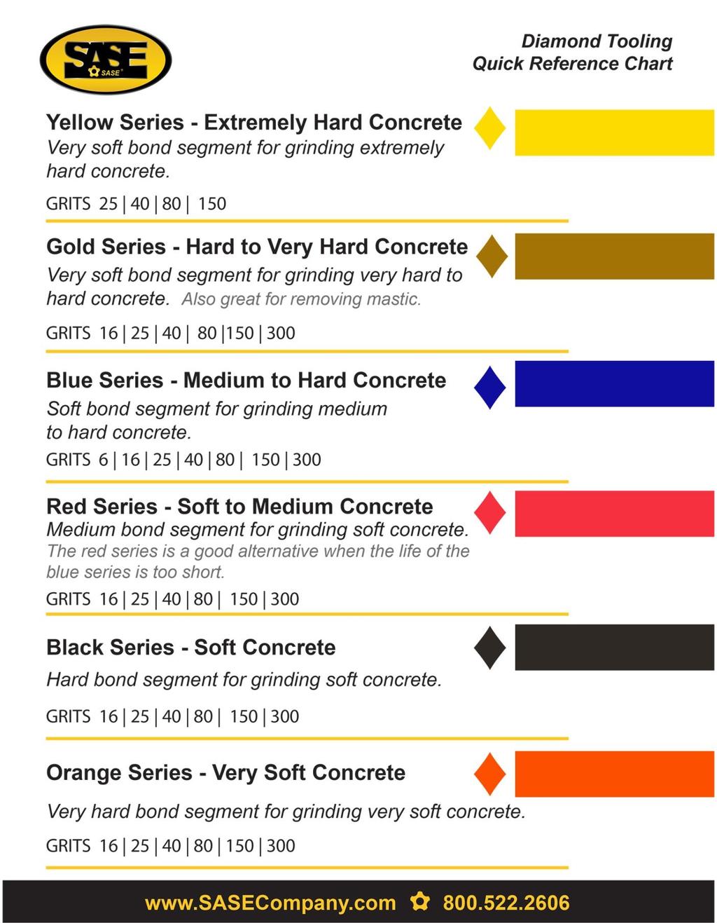
4 Determining Diamond Selection Diamond Background Diamond abrasives usually consist of 2 components: Diamond powder (also known as diamond crystals or grit). By changing the size of the diamond powder or grit, we can change how coarse or fine the scratches will be that are left behind from the grinding process. A binding agent (metal or resin). Diamond powder is mixed and suspended in either a metal or resin binding agent. When suspended in a metal bond matrix, the finished product is referred to as a Metal Bond or Sintered diamond segment. When suspended in a resin bond matrix, the finished product is referred to as a Resin Bond diamond segment or pad. General Diamond Principles Diamond Grit Size: Changing the size of the diamond grit to a smaller particle/ grit size will affect the performance of the diamond tool in the following ways: Create a finer scratch pattern. Increase the life of the diamond tool. The opposite will occur when changing to a larger particle/grit size. The Binding Agent/Metal Bond or Resin Bond: Increasing hardness of bond will Increase life of diamond tool. Decrease production rate. Cause diamond tool to leave finer scratches in dry grinding applications (when compared to a softer bond diamond tool with the same diamond grit size). A hard bond matrix should be used on a soft floor and a soft bond matrix should be used on a hard floor. Grinding disc set-up: The set-up of diamond segments on the grinding heads of the machine will influence the performance of the machine, the productivity levels and also the finished floor quality. There are basically two types of diamond configurations that can be used when grinding: Changing of Diamonds Different applications often require different selections of diamond tooling. There will be many occasions when the grinding discs need to be changed. Following is a guide for this procedure. Preparation Turn off the clutch, and then turn the key to the off position. As an extra precaution, unplug battery from motor, to avoid unintentional starting of the machine while changing disc, which could result in serious injury. WARNING It is highly recommended to have a set of gloves ready, as diamonds can get very hot, especially during dry grinding applications. Changing 1. Set handle in upright position. 2. Pull back on handle to lift grinding head off the ground (Illustrated middle right). 3. Lay machine back on the ground 4. Put on gloves. 5. Remove grinding disc from flex plate. 6. Check to ensure that all discs are secure. 7. Once new diamonds have been attached, reverse procedure to lower machine to ground. 8. As new diamonds may be a different height than the set being previously used, re-adjust skirt to ensure good seal is established with the floor. HALF-SET OF DIAMONDS When the diamonds are set-up as a half-set, they tend to follow the surface of the floor. The half-set diamond configuration should only be used when an extremely flat floor finish is not required. 1. Half set of diamonds when there are diamonds placed at three alternating positions on the diamond holder discs. ( See pictures on upper right). 2. Full set of diamonds when there are diamonds placed at each of the six positions on the diamond holder discs. (See pictures on middle right). FULL-SET OF DIAMONDS Diamonds that are set-up as a full-set tend to not follow the surface of the floor. If the floor is wavy the machine will grind the high areas yet miss the low spots. The full-set diamond configuration should be used when a very flat floor finish is desired.
5
6 Personal Safety Reminder Please read the operator s manual carefully and make sure you understand the instructions before using the machine. WARNING! Dust forms when grinding which can cause injuries if inhaled. Use an approved breathing mask. Always provide for good ventilation while machine is in use. Always wear approved: Always check oil level before starting. Only qualified personnel should be allowed to operate machinery. Never use a machine that is faulty. Carry out the checks, maintenance and service instructions described in this manual. All repairs not covered in this manual must be performed by a repairer nominated by either the manufacturer or distributor. Always wear personal safety equipment such as sturdy non-slip boots, ear protection, dust mask and approved eye protection. The machine should not be used in areas where potential for fire or explosions exist. Machinery should only be started when grinding heads are resting on the ground. Protective helmet Hearing protection The machine should not be started without the rubber dust skirt attached. It is essential a good seal between floor and machine be established for safety, especially when operating in dry grinding applications. Dust Mask Protective goggles When changing the grinding discs ensure the unit is OFF by turning the Key OFF, and set the clutch to OFF. Disconnecting the battery would add another layer of protection. The machine should not be lifted by handles, motor, chassis or other parts. Transportation of the machine is best done on a pallet / skid to which the machine must be firmly secured. Non-slip boots with steel toe Protective gloves Extreme caution must be used when moving machinery by hand on an inclined plane. Even the slightest slope can cause forces/ momentum making the machinery impossible to brake manually. WARNING Under no circumstances may the machine be started without observing the safety instructions. At no time should lifting of machinery be attempted without mechanical means such as a hoist or a forklift. Should the user fail to comply with these, SASE Company Inc or its representatives are free from all liability both directly and indirectly. Read through these operating instructions and make sure that you understand the contents before starting to use the machine. Should you, after reading these safety instructions, still feel uncertain about the safety risks involved you must not use the machine, please contact your SASE representative for more information. Never use the machine if you are tired, if you have consumed any alcohol, or if you are taking medication that could affect your vision, your judgment or your coordination. Never use a machine that has been modified in any way from its original specification. Be on your guard for electrical shocks. Avoid having body contact with lightning conductors/metal in the ground. Do not disconnect the static strap, this should discharge a great deal of static that is generated during grinding concrete.. Follow Propane gas safety regulations at all times.
7 SAFTY WARNING CARBON MONOXIDE can cause severe nausea, fainting or death. Do not operate engine in closed or confined area without proper ventilation! A CO (Carbon Monoxide) monitor is recommended when operating inside.
8 PDG 5000 HANDLE ASSEMBLY SCALE: 1:5 WEIGHT: SHEET 1 OF 1
9 Handle Assembly Item No. Part No. Description Quantity 1 PDG FRAME, PROPANE 1 2 PDG HANDLE, STEM V2 1 3 PDG SPLINE, FEMALE 1 4 PDG LOCK, STEM MALE 1 5 PDG COVER, STEM LOCK ACTION 1 6 NB STUD, DOUBLE END THREADED M X PDG KNOB, BALL THREADED 1 8 PDG LOCK, STEM FEMALE 1 9 NB WASHER, FLAT M8 ZINC 1 10 PDG SPRING, RETURN COMPRESSION M13.75 X 1.25 X NB SCREW, SOCKET HEAD CAP M X PDG CAP, STEM LEFT 1 13 NB SCREW, FLAT HEAD SOCKET CAP M5-0.8 X NB SCREW, FLAT HEAD SOCKET CAP M6-1.0 X NB SCREW, SOCKET HEAD CAP M6-1.0 X 12 ZINC 3 16 NB SCREW, BUTTON HEAD M5 X 12 ZINC PDG COVER, WITH HOLE 1 18 PDG GROMMET, RUBBER 1/2" ID 1 1/8" OD 1 19 PDG PANEL, CLUTCH SWITCH 1
10 PDG 5000P DRUM FINAL SCALE: 1:7 WEIGHT: SHEET 4 OF 4
11 DRUM FINAL Item No. Part No. Description Quantity 1 PDG DRUM, COMPLETE 1 2 PDG FLEXHEAD, COMPLETE W/ GREEN SPRING 3 3 NB WASHER, LOCK M8 9 4 NB SCREW, SOCKET HEAD CAP M8 X SEE PAGE TOOLING, COMPLETE 3 6 NB SCREW, FLAT HEAD SOCKET CAP M X PDG SHROUD, MOLDED VACUUM PDG RUBBER, EPDM GASKET 8 9 NB SCREW, FLANGED HEX HEAD CAP M6-1.0 X 12 NON-SERRATED 6 10 PDG NIPPLE, 1/4" X CLOSE GALV 2 11 PDG ELBOW, BRASS FEMALE 1/4 NPT X 1/4 NPT 2 12 PDG VALVE, 1/4 BALL 2 13 PDG FITTING, PUSH TO CONNECT 3/8 X 1/ PDG TUBING, WATER 5 FT 15 NB SCREW, SOCKET HEAD CAP M X NB WASHER, FLAT M10 ZINC 2 16 PDG WEIGHT, PRO DRUM 4 17 PDG DUST SKIRT, RUBBER DUST 1


12 PDG 5000 BELT BOX UPPER SCALE: 1:50 WEIGHT: SHEET 1 OF 1
13 BELT BOX UPPER Item No. Part No. Description Quantity 1 HON.GXV390 MOTOR W/ CONVERSION 1 1 PDG CONVERSION, PROPANE 1 2 SEE PAGE DRUM AND LOWER BOX PARTS 1 3 PDG PLATE, MOTOR 1 4 NB SCREW, FLAT HEAD SOCKET CAP M X NB NUT, HEXAGONAL JAM M8 1 6 NB SCREW, FLAT HEAD SOCKET CAP M X PDG BLOCK, TENSIONER 2 8 NB SCREW, FLAT HEAD SOCKET 5/16-24 X 1-1/ ZINC 2 9 NB SCREW, FLAT HEAD SOCKET 5/16-24 X 1-1/ ZINC 2 10 NB NUT, 5/16-24 ZINC (NUT GOES ON 9) 2 11 PDG SPACER, CLUTCH 1 12 PDG CLUTCH, 1 13 PDG RETAINER, CLUTCH BEARING 1 14 NB WASHER, 7/ NB HEX BOLT 7/ NB SCREW, HEX M8 X 20 ZINC 4 17 NB WASHER, FLAT M8 ZINC 4 18 NB NUT, HEXAGONAL M NB SCREW, HEX M X 120 FULL THREAD 10.9 ZINC 2 20 NB WASHER, FLAT M10 ZINC 2 21 PDG COVER, REAR 1 22 NB SCREW, SOCKET HEAD M PDG GROMMET, RUBBER 1/2" ID 3/4" OD 1


14 11 BELT MUST BE INSTALLED BEFORE 10 OR BOLTS DOWN INTO DRUM PDG 5000 BELT BOX LOWER SCALE: 1:20 WEIGHT: SHEET 1 OF 1
15 Lower Box Item No. Part No. Description Quantity 1 PDG HOUSING, BELT 1 2 SEE PAGE ASSEMBLY 1 3 NB WASHER, LOCK M8 ZINC 4 4 NB SCREW, SOCKET HEAD CAP M X ZINC 4 5 PDG SPACER, MOTOR ROTO 2 6 NB WASHER, LOCK M14 ZINC (WASHERS DO NOT FIT, NO LONGER USE) 0 7 NB SCREW, SOCKET HEAD CAP M X ZINC 4 8 PDG BELT 1 9 NB PIN, DOWEL M6 X 8MM 2 10 PDG COVER, TOP 1 11 NB SCREW, FLAT HEAD TORX SOCKET CAP M6-1.0 X 20 4


16 PDG 5000 Transfer Pulley SCALE: 1:10 WEIGHT: SHEET 1 OF 1
17 Transfer Pulley Item No. Part No. Description Quantity 1 PDG HOUSING, LOWER BEARING 1 2 PDG BEARING, RS1 2 3 NB RING, SMALLEY INTERNAL RETAINING M PDG SEAL, SHAFT 1 5 PDG SHAFT, TRANSFER 1 6 NB KEY, MOTOR M8 X 7 X NB KEY, SQUARE M10 X PDG SPROCKET, 8MX-63S PDG BUSHING, MM TAPERLOCK 1 10 PDG HOUSING, UPPER BEARING 1 11 PDG SPIDER, LOVEJOY CJ24/32 RED 1 11 PDG COUPLING, LOVEJOY FLEX SIZE 24 HUB 28 1
18 PDG 5000P FRAME, BRACKET & WHEELS SCALE: 1:8 WEIGHT: SHEET 6 OF 6
19 PROPANE FRAME Item No. Part No. Description Quantity 1 SEE PAGE FRAME W/ HANDLE 1 2 PDG WHEEL 2 3 PDG BUSHING, WHEEL AXLE 4 4 NB SCREW, HEX M X 160 ZINC 2 5 NB NUT, JAM M PDG BRACKET, PROPANE TANK 1 7 NB SCREW, HEX M8 X NB WASHER, LOCK M8 4 9 NB NUT, HEX M SEE PAGE DRUM WITH MOTOR 1 11 PDG BUSHING, 1.3 OD 1.15 ID 1.18 LG 1 12 PDG SLEEVE, CARRIAGE BOLT 1 13 NB SCREW, HEX HEAD CAP M12 X NB SCREW, SOCKET HEAD CAP M6-1.0 X ZINC 4 15 PDG SWITCH, IGNITION 1 16 PDG METER, HOUR/TACH DIGITAL 1 17 PDG CABLE, THROTTLE VERNIER 1 18 NB CLAMP, LOOP 3/4" WIDE, 2-1/2" ID 1 19 NB SCREW, FLANGED HEX HEAD CAP M X 12 NON-SERRATED ZINC 1 20 PDG HARNESS, WIRING 1 21 NB CLAMP, ADEL 3/8" 2 22 NB SCREW, HEX HEAD CAP M5-0.8 X 10 ZINC 8.8 2
20 PDG 5000P FRAME SCALE: 1:8 WEIGHT: SHEET 1 OF 6
21 PROPANE FRAME Item No. Part No. Description Quantity 1 PDG BRACKET, WATER TANK LEFT 1 2 PDG BRACKET, WATER TANK RIGHT 1 3 PDG TANK, WATER 1 4 NB SCREW, HEX 5/16-18 X 3/4 ZINC 4 5 PDG NIPPLE, 1/4" X CLOSE GALV 1 6 PDG FITTING, 1/4 NPT ALL FEMALE "T" 1 7 PDG FITTING, 1/4 NPT MALE X 1/4 BARB 2 8 NB NUT, M NYLOC 4 9 NB WASHER, FLAT M8X17X NB SCREW, HEX M8 X SEE PAGE FRAME, W/ WHEELS 1 12 PDG STICKERS, KIT 5K PRO 1 13 HON REGULATOR, RECTIFIER PROPANE GXV NB SCREW, FLANGED HEX HEAD CAP M6-1.0 X 16 NON-SERRATED ZINC 2 14 NB SCREW, BUTTON HEAD SOCKET M8 X PDG BOX, BATTERY 1 16 PDG BATTERY, 12V 1 17 PDG FITTING, BRASS 1/8" NPT THROUGH WALL 1 18 PDG NIPPLE, 1/8" X CLOSE BRASS 1 19 Part Of Motor VACUUM SOLENIOD 1 OTHER PARTS FOR MOTOR Item No. Part No. Description Quantity a HON BOLT 2 b HON HARNESS, SUB WIRE PROPANE GXV390 1 c HON COIL, 10 AMP PROPANE GXV390 1


22 PDG 5000 Complete Drum SCALE: 1:1 WEIGHT: 61.77kg SHEET 1 OF
23 Complete Drum Item No. Part No. Description Quantity 1 See Page 22 Bottom Drum Assembled 1 2 PDG BELT, MAIN PJ18 M See Page 16 Top Plate Assembled 1 4 NB SCREW, SOCKET HEAD CAP M X 85 ZINC 2 5 PDG BELT, TOP 380PJ PDG BUTYL FLEX 5 oz 7 PDG SHROUD, BTM BELT DUST 1 8 NB SCREW, HEX HEAD CAP M5-0.8 X 10 ZINC PDG TAPE, PRESERVATION HEAT SHRINK 3" WHITE 15 ft 10 PDG RING, UPPER DUST 1 11 NB SCREW, SOCKET HEAD CAP M6-1.0 X ZINC 7 11b NB WASHER, M6 INTERNAL LOCK 6 12 PDG SEAL, TOP BELT 1 13 PDG ZIP TIE, 48" 2 14 PDG EAR, MOUNTING V NB SCREW, FLAT HEAD SOCKET CAP M X PDG CHEMREX CX oz 17 PDG PLATE, STATIONARY 1 18 NB SCREW, FLAT HEAD SOCKET CAP M6-1.0 X PDG SEAL, AXLE NITRILE AL. SLURRY COVERS 3 20 PDG SILICONE, CRYSTAL CLEAR 1.5 oz 21 PDG COVER, PLANETARY SLURRY ALUMINUM 3 22 NB SCREW, SOCKET HEAD CAP M6-1.0 X ZINC 9 Complete Drum Supplemental 2 PDG Belt tension over longest span Hz 1 4 NB Red Loctite PDG Belt tension over longest span Hz 1 8 NB Red Loctite NB Red Loctite NB Red Loctite NB Red Loctite 263, anti-sieze applied to countersink NB Red Loctite 263 9

24 PDG 8000 Top Drum SCALE: 1:10 WEIGHT: 17.3kg SHEET 1 OF 1
25 Top Drum Item No. Part No. Description Quantity 1 PDG Top Plate 1 2 PDG.4A Steel PTO Assembled 1 3 PDG.4A Top Tightener Assembled 1 4 PDG Top Tightener Actuator 1 5 PDG.4A Top Idler Assembled 1 6 PDG.4A Drum Sheave Assembled 1 7 PDG Tightener Clamp 3 8 NB M6-1.0x12 Socket Head Cap Screw 3 9 PDG Upper Counter Weight Half Moon 1 10 NB M10 Out/M6 In, Threaded Insert (Required in aluminum Top Plate) 0 11 NB M6-1.0x16 Flat Countersunk Head Screw NB M8-1.25x20 Flat Countersunk Head Screw 2 13 NB M8-1.25x20 Socket Head Cap Screw 2 Top Drum Supplemental 8 NB Red LocTite NB Red LocTite NB Red LocTite NB Red LocTite NB Red LocTite Start with #1, Insert #5, Bolt down with #12, then remove the sheave from #5. Insert #2, bolt down with #11. Insert #3, Insert #7, bolt down with #8. replace the sheave to #5. Insert #4, bolt down with #12. Now CHECK the height of #3 and #5. If they are even, go on. If they are uneven, Insert NB spacer to level them. The rest of the parts can be added once #3 and #5 are in place and even at the top edge.
26 Rev PDG 5000 Bottom Drum 26 SCALE: 1:3 WEIGHT: 22 Kg SHEET 1 OF
27 Bottom Drum I Item No. Part No. Description Quantity 1 PDG PLATE, BTM DRUM 1 2 NB SCREW, SOCKET HEAD CAP M6-1.0 X 12 ZINC 6 3 PDG STANCHION, PERIMETER 5 4 PDG.4A SUBASSEM, MAIN BELT SPINDLE 1 5 PDG WEIGHT, BALANCE 1 6 NB SCREW, SOCKET HEAD CAP M6-1.0 X ZINC 11 7 NB PIN, SPIRAL M3 X PDG POST, REACTION 1 Bottom Drum I Supplemental 2 NB Red LocTite NB Red LocTite

28 PDG 5000 Bottom Drum II SCALE: 1:10 WEIGHT: 26 Kg SHEET 1 OF
29 Bottom Drum II Item No. Part No. Description Quantity 1 PDG.4A SUBASSEM, MAIN IDLER 1 2 NB SCREW, SOCKET HEAD CAP M6-1.0 X 12 ZINC 6 3 PDG.4A SUBASSEM, MAIN TIGHTENER 1 4 NB SCREW, FLAT HEAD SOCKET CAP M6-1.0 X PDG ROD, TIGHTENER 1 6 NB NUT, COUPLING M NB NUT, JAM M ZINC 1 8 NB NUT, NYLOC M10 ZINC 1 9 NB WASHER, SPHERICAL M See Page 18 Bottom Drum I 1 Bottom Drum II Supplemental 2 NB Red LocTite NB Red LocTite PDG Red LocTite 263, where #3, #6 and #7 mount. #8 gets no LocTite 1 8 NB Tighten to #7, all the way to one end of #5(threaded rod). Do Not LocTite 1
30 PDG 5000 Bottom Drum Rev 7 30 SCALE: 1:3 WEIGHT: 36 Kg SHEET 3 OF
31 Bottom Drum III Item No. Part No. Description Quantity 1 PDG.5A SUBASSEM, PLANETARY 3 2 NB SCREW, SOCKET HEAD CAP M6-1.0 X See Page 20 Bottom Drum II 1 Bottom Drum III Supplemental 1 PDG.5A Butyl Flex is added on the flat face where bolts enter, through the bottom drum. 3 2 NB Red LocTite
32 PDG 5000 Drum Sheave Assembly Rev 7 32 SCALE: 1:4 WEIGHT: 9.5kg SHEET 1 OF
33 Drum Sheave Item No. Part No. Description Quantity 1 PDG SHEAVE, STATIONARY DRUM 1 2 NB SCREW, FLANGED HEX HEAD M6-1.0 X 20 NON 16 3 PDG SPACER, OUTER STAT SHEAVE 1 4 PDG SPACER, INNER STAT SHEAVE 1 5 PDG BEARING, RS 2 6 PDG SPINDLE, MAIN DRUM SHEAVE 1 PDG.4A SUBASSEM, DRUM SHEAVE 1 Drum Sheave Supplemental 2 NB Red LocTite
34 PDG 5000 Top Idler Rev 6 Rev 7 34 SCALE: 2:3 WEIGHT:.212kg SHEET 1 OF
35 Top Idler Item No. Part No. Description Quantity 1 PDG SPINDLE, TOP IDLER 1 2 PDG CAP, BEARING 1 3 NB SCREW, FLAT HEAD SOCKET CAP M X PDG BEARING, RS 1 5 PDG BEARING, RSJ 1 6 NB PIN, SPIRAL M3 X PDG SHEAVE, TOP TIGHTENER 1 PDG.4A SUBASSEM, TOP IDLER 1 Top Idler Supplemental 3 NB Red LocTite 263 1
36 Note: There is no amount of pin or screw showing on the bottom in this side view. The bottom must be truely flat. 1 5 PDG 5000 Top Tightener Rev 7 36 SCALE: 1:2 WEIGHT:.39kg SHEET 1 OF
37 Top Tightener Item No. Part No. Description Quantity 1 PDG GEAR, TOP TIGHTENER 1 2 PDG SPINDLE, TOP TIGHTENER 1 3 PDG CAP, BEARING 1 4 PDG BEARING, RSJ 1 5 NB SCREW, FLAT HEAD SOCKET CAP M X PDG BEARING, RS 1 7 NB PIN, SPIRAL M3 X PDG SHEAVE, TOP TIGHTENER 1 PDG.4A SUBASSEM, TOP TIGHTENER 1 Top Tightener Supplemental 5 NB Red LocTite NB Insert pin into 2 all the way, Careful not to crush either end in the process. Then 2&7 into 1. fasten bottom screw, fasten top screw. 1

38 PDG PTO Assembly SCALE: 1:5 WEIGHT: 4.0kg SHEET 1 OF
39 Power Take Off (PTO) Item No. Part No. Description Quantity 1 PDG HOUSE, PLANETARY BEARING 1 2 PDG BEARING, RS 1 3 NB RING, INTERNAL RETAINING M PDG RETAINER, SHEAVE STEEL 1 5 PDG SHEAVE, PTO STEEL 1 6 PDG AXLE, PTO 1 7 NB SCREW, FLAT HEAD SOCKET M X 25 ZINC 1 PDG.4A SUBASSEM, PTO 1 Power Take Off (PTO) 7 NB Red LocTite 263, Torque 35 Ft-Lbf 1

40 PDG Main Tightener SCALE: 1:4 WEIGHT: SHEET 2 OF
41 Main Tightener Item No. Part No. Description Quantity 1 PDG PLATE, BTM TIGHTENER 1 2 PDG STANCION, TIGHTENER 1 3 PDG SPACER, BEARING 2 4 PDG SPINDLE, TIGHTENER BEARING 1 5 PDG BEARING, RS 1 6 NB SCREW, FLAT HEAD SOCKET CAP M6-1.0 X PDG PLATE, TOP TIGHTENER 1 8 PDG POST, TIGHTENER PIVOT 1 9 PDG GRUDEGEON, TENSIONER 1 10 PDG O-RING, TIGHTENER DASH NB SCREW, FLAT HEAD SOCKET M6-1.0 X 16 2 PDG.4A SUBASSEM, MAIN TIGHTENER 1 Main Tightener Supplemental 6 NB Red LocTite PDG This is easy to lose NB Red LocTite 263 2

42 PDG 5000 Main Belt Drive SCALE: 1:4 WEIGHT: 1.59kg SHEET 2 OF
43 Main Belt Drive Item No. Part No. Description Quantity 1 NB WASHER, SPRING M30.5 X 46.5 X PDG SPINDLE, MAIN DRIVE 1 3 PDG BEARING, RS 2 4 PDG SHEAVE, MAIN DRIVE 1 5 NB RING, EXTERNAL RETAINING M PDG COUPLER, DRIVEN MOTOR 1 7 NB SCREW, SOCKET HEAD CAP M5-0.8 X 16 8 PDG.4A SUBASSEM, MAIN BELT SPINDLE 1 Main Belt Drive Supplemental 3 PDG into 4 outter race press, 3 over 2 inner race press. 2 7 NB Red LocTite 263 8

44 PDG 5000 Main Idler Rev 7 44 SCALE: 1:2 WEIGHT: 1.25kg SHEET 1 OF
45 Main Idler Item No. Part No. Description Quantity 1 PDG SPINDLE, MAIN IDLER 1 2 PDG BEARING, RS 1 3 PDG RETAINER, IDLER BEARING 1 4 NB SCREW, FLAT HEAD SOCKET CAP M5-0.8 X 16 2 PDG.4A SUBASSEM, MAIN IDLER 1 Main Idler Suplemental 4 NB Red LocTite 263 2

46 PDG 5000 Planetary SCALE: 1:8 WEIGHT: SHEET 1 OF
47 Planetary Item No. Part No. Description Quantity 1 NB PIN, HARDENED M8 X PDG AXLE, PLANETARY 1 3 PDG HOUSE, PLANETARY BEARING 1 4 PDG BEARING, RS 1 5 NB RING, INTERNAL RETAINING M PDG ROTOR, SPINDLE 1 7 PDG SHEAVE, PLANETARY 1 8 NB SCREW, FLAT HEAD SOCKET CAP M6-1.0 X PDG WASHER, SPINDLE TOP 1 10 NB SCREW, SOCKET FLAT HEAD CAP M10-1. X NB NUT, HEX FLANGE M PDG.5A SUBASSEM, PLANETARY 3 Planetary Supplemental 8 NB Red LocTite NB Red LocTite 263, at tip NB Tighten to 40 ft-lbf, with #10 captured. 1
48 PDG 5000 Flex Head SCALE: 1:10 WEIGHT: SHEET 1 OF 1
49 Flex Head Item No. Part No. Description Quantity 1 PDG YOKE, SUSPENSION 4 2 PDG BUSHING, YOKE 4 3 PDG ELEMENT, CENTER STUDDED 1 4 PDG PLATE, DRIVING 1 5 PDG PLATE, DRIVEN 1 6 NB SCREW, FLAT HEAD SOCKET CAP M X PDG LOCK, SHAMROCK PLATE ASSEM 1 8 NB SCREW, FLAT HEAD SOCKET CAP M X 16 ZINC 7 9 PDG POST, SPRING 4 10 PDG SPRING, DIE GREEN 4 11 NB RING, EXTERNAL 1/2" 4 PDG FLEX HEAD, COMPLETE 1 Flex Head Supplemental 6 NB Red LocTite NB Red LocTite 263 7
50 PDG 5000 Tooling Plate SCALE: 1:5 WEIGHT: SHEET 1 OF
51 Tooling Plates Item No. Part No. Description Quantity 1 HOL QCS METAL BOND ADAPTERS 3 2 NB SCREW, FLAT HEAD SOCKET CAP M6 X PDG PLATE, TOOLING PDG5K 1 4 PDG MAGNET, 5/8" OD X 1/8" THICK WITH CS HOLE NORTH 3 5 NB SCREW, M4 X 6 FLAT HEAD PHILLIPS S/S 3 Tooling Plates Supplemental 5 NB Green LocTite NB Red LocTite 263 9
52 BELT TENSIONS 132 ±12 Hz 245 ±22 Hz or ft/lb MAIN BELT TOP BELT PTO Sheave Located on Top Plate PDG 5000 Belt Paths SCALE: 1:1 WEIGHT: 61.77kg SHEET 1 OF
53 SASE MANUFACTURER S WARRANTY POLICY Included in this warranty are the following pieces of equipment: Planetary Diamond Grinders: PDG 8000, PDG 6000, PDG 5000, Edge Pro 180 Dust Extractors: Bull 1250, Bull 300, Bull 45 Our Commitment to our customer: SASE Company ( SASE ) equipment is warranted to be free of defects in workmanship and materials for a period of one (1) year from original date of purchase. In the event that you should have a claim SASE shall repair, replace or remedy the defective parts resulting from the faulty design, materials or workmanship. Note: This warranty is only valid for equipment either sold by SASE or by an authorized wholesaler or distributor. Limitations: Warranty does not apply to cosmetic damage, damage due to lightning, electrical surgmisuse, abuse, repair or alteration by other than factory service (unless service center was approved in writing by SASE), negligence, or improper or neglected maintenance as recommended by SASE. Common ware parts, such as belts, bearexempt from warranty. SASE is not responsible for loss of income or down time as a result faulty design, materials or workmanship. Warranty coverage is valid once a warranty SASE. A $100 labor charge may be assessed on the items returned for warranty repair in which no fault is found. Freight charges and associated fees will then become the responsibility of the customer in such an instance. Damages which are caused during transportation are not covered under warranty. Such carrier. Claims: In the unlikely event that you should experience a defect please contact your SASE representative or a SASE service technician by calling Please have all pertinent information readily available such as, invoice with date of purchase, model and serial number, and an explanation of the issue. SASE will respond immediately with a corrective action. Freight responsibility for approved warranty claims: If the piece of equipment was purchased within 90 days of warranty claim, SASE will arrange for ground freight and will assume all ground freight charges to send the customer the parts required or to send the equipment to an authorized SASE repair center. This includes inbound and outbound ground freight and all fees (duties, fuel surcharges) associated with the shipment. If the piece of equipment was purchased beyond 90 days and prior to one (1) year of warranty claim, SASE will cover 50% of all ground freight charges, including inbound and outbound freight and all fees (duties, fuel surcharges) associated with the shipment.
54 SASE PRODUCT & WARRANTY REGISTRATION WARRANTY IS VOID IF NOT RETURNED AND REGISTERED WITH SASE WITHIN 30 DAYS OF PURCHASE COMPANY NAME AND TITLE STREET ADDRESS CITY STATE ZIP COUNTRY PHONE DATE OF PURCHASE SERIAL NUMBER INVOICE NUMBER OF PURCHASE PDG 8000 PDG 6000 PDG 5000 EDGE PRO 180 SC8E SC10E SC12E BULL 1250 BULL 300 BULL 45 PLEASE FILL OUT IN FULL AND SUBMIT TO: SASE COMPANY 2475 STOCK CREEK BLVD ROCKFORD TN, FAX: QUESTIONS? CALL
 SASE Planetary Diamond Grinders PDG 4500 230 volt 50/60 HZ single phase 8464.20.")
55 Corporate Office th Ave South Kent, WA (P) (F) Certificate of Declaration and Conformity: (Applies to Europe only) SASE Planetary Diamond Grinders PDG volt 50/60 HZ single phase PDG volt 50/60 HZ three phase PDG volt 50/60 HZ three phase PDG volt 50/60 HZ three phase PDG volt 50/60 HZ three phase PDG volt 50/60 HZ three phase PDG volt 50/60 HZ three phase SASE Company hereby certifies that the above listed Planetary Diamond Grinders are classified within the following EU directives of conformity for CE markings: EU Machinery directive 2006/42/EC EU Low voltage directive 2006/95/EC EU Electromagnetic compatibility directive 2004/108/EC and further conform with the following EU Harmonized Standards: EN :2007 EN : A1:2009 EN :2007 EN :2007
PDG 5000 PROPANE MANUAL
 PDG 5000 PROPANE MANUAL SASE Company, Inc. 800.522.2606 www.sasecompany.com Version: 5K04R3 Serial: 2000-2500 4/27/2018 2 -.' ---... *SASE. Corporate Office 26423 79 th Ave South Kent, WA 98032-7321 1.800.522.2606
PDG V PLANETARY EDGER. SASE Company, Inc. Phone or Fax
 PDG 3000 460V PLANETARY EDGER SASE Company, Inc. Phone 800.522.2606 or Fax 877.762.0748 www.sasecompany.com Version 1.2 9/27/2017 Corporate Office Details 26423 79th Ave South Kent, WA 98032-7321 1.800.522.2606
Safety Instructions Introduction Transportation Storage Setup and Operation Changing of Diamonds...
 Table of Contents Safety Instructions... 2 Introduction... 4 Transportation... 4 Storage... 4 Setup and Operation... 5 Changing of Diamonds... 7 Determining Diamond Selection... 9 Final Assembly... 11
Corporate Office th Ave South Kent, WA (P) (F) sa ny.
 (F) sa ny.") Version 7.3 Ser. #: 2000 to 3000 Date: 01/01/2018 2 -.' ---... *SASE. Corporate Office 26423 79 th Ave South Kent, WA 98032-7321 1.800.522.2606 (P) 1.877.762.0748 (F) www.sasecompany.com sa les@sasecompa
Version 7.3 Ser. #: 2000 to 3000 Date: 01/01/2018 2 -.' ---... *SASE. Corporate Office 26423 79 th Ave South Kent, WA 98032-7321 1.800.522.2606 (P) 1.877.762.0748 (F) www.sasecompany.com sa les@sasecompa
DIAMOND MODEL CC1900 EARLY ENTRY CONCRETE SAW PARTS LIST P R O D U C T S. (March 2012) Part #
 Part #") DIAMOND P R O D U C T S EARLY ENTRY CONCRETE SAW PARTS LIST MODEL CC1900 (March 2012) Part #1801617 (Intentionally Blank) TABLE OF CONTENTS Description Page No. Frame Assembly....4-5 Engine Assembly......6
DIAMOND P R O D U C T S EARLY ENTRY CONCRETE SAW PARTS LIST MODEL CC1900 (March 2012) Part #1801617 (Intentionally Blank) TABLE OF CONTENTS Description Page No. Frame Assembly....4-5 Engine Assembly......6
Table of Contents Cover 1 Letter from Owner 3 Table of Contents 5 Introduction 6 Diamond Tooling 7 Changing Diamonds 8 Personal Safety 9 Diamond
 Version 14 Ser #: 1300-1400 Date: 4/7/2016 Table of Contents Cover 1 Letter from Owner 3 Table of Contents 5 Introduction 6 Diamond Tooling 7 Changing Diamonds 8 Personal Safety 9 Diamond Tooling Quick
DUAL HEAD FLOOR GRINDER PARTS LIST MODEL CC200
 DUAL HEAD FLOOR GRINDER PARTS LIST MODEL CC00 September 0 Part #8000 Table of Contents Description Page No. Frame Assembly.. - Disc Assembly..... 6 Flange Assembly.. Engine Group, 0 HP HondaGas. 8 Gear
PARTS LIST COMMANDER 20 VAC-TRAC COMMANDER 27 VAC-TRAC FH 541V
 PARTS LIST COMMANDER 20 VAC-TRAC COMMANDER 27 VAC-TRAC FH 541V UPPER ASSEMBLY 101 6190481 THROTTLE CABLE FOR MODELS WITH ADDITIONAL CHOKE CABLE 1 101 6190751 THROTTLE CABLE FOR MODELS WITH OUT ADDITIONAL
MODEL 83 Pail Handler
 MORSE MFG. CO., INC. 727 West Manlius Street P.O. Box 518 East Syracuse, NY 13057-0518 Phone: 315-437-8475 Fax: 315-437-1029 Email: service@morsemfgco.com Website: www.morsemfgco.com COPYRIGHT 2005 MORSE
PDG Manual. SASE Company, Inc. Phone or Fax
 PDG 9500+ Manual SASE Company, Inc. Phone 800.522.2606 or Fax 877.762.0748 www.sasecompany.com Version 5 Ser. #: 2300 + Date : 8/1/2018 Table of Contents Cover... 1 Letter from SASE Safety Instructions
Parts Manual for: MODELS / I.D. : / ZTH5223A / ZTH5225A / ZTH6125A
 Parts Manual for: MODELS / I.D. : 968999153 / ZTH5223A 968999154 / ZTH5225A 969999155 / ZTH6125A Husqvarna policy is to improve its products whenever it is possible and practical to do so. In an effort
GP ONE SPLIT DECK 9/4/2012 COPYRIGHT 6/10/10 ALL RIGHTS RESERVED
 GP ONE SPLIT DECK PAGE G & P ONE GRINER SPLIT DECK SUB ASSEMBLY PARTS BREAK DOWN 4 2 24 20 2 6 0 36 24 7 27 2 2 25 3 32 2 24 28 24 8 7 24 5 2 25 2 20 2 4 3 2 34 5 26 22 2 27 35 22 3 30 6 9 29 8 29 2 9
ATBG280/6 Bench Grinder Bench Grinder ATBG280/6 230V-50Hz 280 Watt 150mm x 25mm Wheel size
 Bench Grinder ATBG280/6 230V-50Hz 280 Watt 150mm x 25mm Wheel size SPECIFICATIONS Model Number : ATBG280/6 Nominal Voltage Power Consumption No load speed Wheel size Weight 230Volt 50Hz 280 Watts 2880
Parts Manual for MODELS: ZKH52222 ZKH52252 ZKH61252
 Parts Manual for MODELS: ZKH52222 ZKH52252 ZKH61252 Professional Quality Lawn Care Equipment since 1945 THIS MANUAL INCLUDES UPDATES ON PAGES 6,10, & 20. Yazoo/Kees Power Equipment policy is to improve
Walk-Behind Lawn Mowers
 Walk-Behind Lawn Mowers Parts Manual Models 2 - PRO21SCH 12 - LM21 1 - LM21S 1 - LM21SW 1 - LM21S 11 - PRO21SCH 0 - LM21SW - LM21S - LM21SW 5 - LM21S - LM21SW 0700 /0 Printed in USA THE MANUAL Before you
COMMERCIAL MOWERS PARTS MANUAL FOR: MODELS: ZKH52221 ZKH52251 ZKH61221 ZKH61251
 PARTS MANUAL FOR: COMMERCIAL MOWERS MODELS: ZKH52221 ZKH52251 ZKH61221 ZKH61251 FD KEES POWER EQUIPMENT, L.L.C. 700-800 PARK AVENUE BEATRICE, NEBRASKA, U.S.A. 68310 PRINTED IN USA MANUAL NO.-102935 REV.
VARIABLE SPEED WOOD LATHE
 MODEL MC1100B VARIABLE SPEED WOOD LATHE INSTRUCTION MANUAL Please read and fully understand the instructions in this manual before operation. Keep this manual safe for future reference. Version: 2015.02.02
TABLE OF CONTENTS DESCRIPTION. Safety Instructions Assembly Operation... 7
 TABLE OF CONTENTS DESCRIPTION PAGE Warranty... 1 Safety Instructions... 2 Assembly... 3 Operation... 7 #360 Grain Cleaner Drawings... 8 #360 Grain Cleaner Parts List... 10 Utility Auger Option Drawing...
EllisSaw.com. EllisSaw.com P.O. Box Verona, WI
 P.O. Box 9019 Verona, WI 9-019 GENERAL OPERATING & SAFETY INSTRUCTIONS * READ INSTRUCTIONS BEFORE USE * CAUTION: Disconnect power supply cord from power source when doing repair work or changing belt.
VARIABLE SPEED WOOD LATHE. Model DB900 INSTRUCTION MANUAL
 VARIABLE SPEED WOOD LATHE Model DB900 INSTRUCTION MANUAL 1007 TABLE OF CONTENTS SECTION...PAGE Technical data.. 1 General safety rules....1-3 Specific safety rules for wood lathe.....3 Electrical information.4
Parts Manual SPDZTR 42 / SPDZTR 42 BF /
 Parts Manual SPDZTR 42 / 966657601 SPDZTR 42 BF / 966657701 Please read the operator s manual carefully and make sure you understand the instructions before using the machine. Gasoline containing up to
CAUTION! This manual contains important information for the correct installation, operation and maintenance of the equipment described herein.
 CAUTION! This manual contains important information for the correct installation, operation and maintenance of the equipment described herein. All persons involved in such installation, operation, and
24 GA. PITTS ROLLFORMER
 1 TIN KNOCKER 24 GA. PITTS ROLLFORMER INSTRUCTIONS & PARTS DIAGRAM Shown with Stand and Optional Flanging Attachment Rev. 092606 TAAG MACHINERY CO. (Master Distributor) 1257-B Activity Dr. Vista, CA 92081
accidents which arise due to nonobservance and the safety information herein. SPECIFICATIONS
 7 TON ELECTRIC LOG SPLITTER Model: 05620 CALIFORNIA PROPOSITION 65 WARNING: You can create dust when you cut, sand, drill or grind materials such as wood, paint, metal, concrete, cement, or other masonry.
Core EZ. Operating Manual. Toll Free B East Broadway Avenue Tampa, FL 33619
 Operating Manual 3702 West Central Avenue Santa Ana, CA 92704 Toll Free 1-866-987-7297 11 High Street Suffield, CT 06078 www.ussaws.com 8004B East Broadway Avenue Tampa, FL 33619 Introduction This manual
Parts Manual RZ4623 /
 Gasoline containing up to 10% ethanol (E10) is acceptable for use in this machine. The use of any gasoline exceeding 10% ethanol (E10) will void the product warranty. Parts Manual RZ4623 / 967009801 Please
 Parts Manual for: MODELS / I.D. : 968999150 / ZTH4217A Husqvarna policy is to improve its products whenever it is possible and practical to do so. In an effort to keep pace with changes in technology,
3/8 Butterfly Air Impact Wrench
 3/8 Butterfly Air Impact Wrench 37730 ASSEMBLY AND OPERATING INSTRUCTIONS 3491 Mission Oaks Blvd., Camarillo, CA 93011 Visit our Web site at http://www.harborfreight.com Copyright 2004 by Harbor Freight
TABLE OF CONTENTS DESCRIPTION. Safety Instructions Assembly Operation... 7
 TABLE OF CONTENTS DESCRIPTION PAGE Warranty... 1 Safety Instructions... 2 Assembly... 3 Operation... 7 #360 Grain Cleaner Drawings... 8 #360 Grain Cleaner Parts List... 10 Utility Auger Option Drawing...
Item# " VARIABLE SPEED BENCH GRINDER USER'S MANUAL
 Power Tools Item# 33309 3" VARIABLE SPEED BENCH GRINDER USER'S MANUAL Read carefully and understand RULES FOR SAFE OPERATION and instructions before operating. Failure to follow the safety rules and other
SRX-2000 PARTS LIST. SRX SRX E Revision 100. Manual Part# PM
 www.mkdiamond.com SRX-000 Early Entry Concrete Saw PARTS LIST MODELS p/n SRX-000 7 SRX-000 7-E Revision 00 0.008 Manual Part# 7-PM Caution: Read all safety and operating instructions before using this
Hydraulic Renovator 20
 Model #: 704591 Starting Date: 2/2005 8HP Kawasaki Engine Hydraulic Renovator 20 ILLUSTRATED PARTS LIST 2 Handle Assembly - Fig. 1 4 7 19 17 9 1 56 58 1 12 14 55 5 16 21 7 8 27 17 0 26 24 6 2 52 4 15 11
Illustrated Parts: Model 853
 Illustrated Parts: Model 853 BCS America LLC 5001 N Lagoon Ave Portland, OR 97217 Revised 09/20/2017 www.bcsamerica.com Phone: 800-543-1040 Fax: 800-777-7069 Bumper Accessories ------ - 823956 01.00 800.010-01.3
GENERAL OPERATIONAL PRECAUTIONS PRECAUTIONS ON USING CUT-OFF MACHINE
 GENERAL OPERATIONAL PRECAUTIONS WARNING! When using electric tools, basic safety precautions should always be followed to reduce the risk of fire, electric shock and personal injury, including the following.
INSTRUCTION BOOKLET AND WARRANTY INFORMATION 6 BENCH GRINDER
 INSTRUCTION BOOKLET AND WARRANTY INFORMATION 6 BENCH GRINDER Part No.: SW1250 PLEASE READ CARE AND SAFETY INSTRUCTIONS BEFORE USE SPECIFICATIONS Part No.: SW1250 Input Voltage: 240V Frequency: 50Hz Rated
Angle Grinder. Model Visit our website at:
 Angle Grinder Safety Guard Model 45921 Installation Instructions Note: Cutting Blade and Angle Grinder sold separately. Visit our website at: http://www.harborfreight.com Read this material before using
MODELS: CC3730TE / CC3740TE
 DIAMOND P R O D U C T S CONCRETE SAW PARTS LIST MODELS: CC0TE / CC0TE February 00 Part #00 Table of Contents Pictorial Page Index....., Belt Guard Assembly... Controls Legend....... Belt Tensioner Assembly....
FRAME. Pull Type Rigid Frame, Lift Rotate INNER HITCH
 Pull Type Rigid Frame, Lift Rotate INNER HITCH The hitch length can be adjusted in 15" increments to accommodate the tractor tire options (single or dual tires) being used and attachments installed on
DIAMOND CONCRETE SAW PARTS LIST MODEL CC1113-XL P R O D U C T S. June Part #
 DIAMOND P R O D U C T S CONCRETE SAW PARTS LIST MODEL CC1113-XL June 013 Part #10 TABLE OF CONTENTS Description Page No. Saw Assembly (Normal Cut).... - Saw Assembly (Up-Cut)...... - Gas Engine Assembly......
HANDHOLE SEAT GRINDER
 1041-1601 HANDHOLE SEAT GRINDER OPERATING INSTRUCTIONS & SERVICE MANUAL Rev: A, 9/17/2007 TO REDUCE THE RISK OF INJURY AND EQUIPMENT DAMAGE USER MUST READ AND UNDERSTAND OPERATOR S MANUAL. Thomas C. Wilson,
WALK-BEHIND SPREADER 50 LB. CAPACITY Model 99623
 WALK-BEHIND SPREADER 50 LB. CAPACITY Model 99623 Assembly, Operating, and Maintenance Instructions Diagrams within this manual may not be drawn proportionally. Due to continuing improvements, actual product
SECTION 7 - SUSPENSION
 For Arctic Cat Discount Parts Call 606-678-9623 or 606-561-4983 SECTION 7 - SUSPENSION TABLE OF CONTENTS Section Front and Rear Suspension Assembly Schematics... 7-2 Shock Absorbers... 7-4 Swing Arms (ACT
Illustrated Pats List
 Illustrated Pats List Automatic Lawn Tractor Models 0 0 0 Model 0 Shown IMPORTANT: READ SAFETY RULES AND INSTRUCTIONS CAREFULLY Warning: This unit is equipped with an internal combustion engine and should
Parts Catalog. S-Series Slicer Manual Frozen Option S13. Model:
 , 07 995 ECN 08 Parts Catalog S S-Series Slicer Manual Frozen Option Model: S 05/0/07 Rev. G IMPORTANT! TO EXPEDITE SHIPMENT OF PARTS, ALWAYS SPECIFY MODEL, REV, PART NUMBER, AND SERIAL NUMBER OF UNIT.
CONCRETE SAW PARTS LIST
 CONCRETE SAW PARTS LIST MODEL CC00XL August 201 Part # 18020 GENERAL SAFETY WARNINGS AND PRECAUTIONS PERSONAL SAFETY Read and understand all operating instructions before attempting to operate the saw.
GENERAL OPERATIONAL PRECAUTIONS PRECAUTIONS ON USING DISC GRINDER
 GENERAL OPERATIONAL PRECAUTIONS WARNING! When using electric tools, basic safety precautions should always be followed to reduce the risk of fire, electric shock and personal injury, including the following.
Angle Grinder MODEL 9553B MODEL 9555B
 ENGLISH Angle Grinder MODEL 9553B MODEL 9555B 006649 DOUBLE INSULATION I N S T R U C T I O N M A N U A L WARNING: For your personal safety, READ and UNDERSTAND before using. SAVE THESE INSTRUCTIONS FOR
Illustrated Parts Manual
 Illustrated Parts Manual Mustang Series RZT TROY-BILT LLC, P.O. BOX CLEVELAND, OHIO -00 Printed In USA Form No. -0 (December, 0) To The Owner Thank You Thank you for purchasing an MTD Zero-Turn Tractor.
ATV CULTIVATOR OWNER S MANUAL
 ATV CULTIVATOR OWNER S MANUAL WARNING: Read carefully and understand all ASSEMBLY AND OPERATION INSTRUCTIONS before operating. Failure to follow the safety rules and other basic safety precautions may
M-5 PRO CORE BORE PARTS LIST DRILLING MACHINE. (March 2017) Part #
 Part #") M- PRO CORE BORE DRILLING MACHINE PARTS LIST (March 07) Part #809 Table of Contents Description Page No. Carriage Assembly....... - Combo Base Assembly....... - 7 Anchor Base Assembly........8 Anchor
M- PRO CORE BORE DRILLING MACHINE PARTS LIST (March 07) Part #809 Table of Contents Description Page No. Carriage Assembly....... - Combo Base Assembly....... - 7 Anchor Base Assembly........8 Anchor
.com. More than a machine. Power your life. Operating Manual
 Operating Manual www.maxnovomachine +86-514-87892928 info@maxnovomachine Dear Customer, Thank you very much for purchasing a product made by MAXNOVO MACHINE. Our machines offer a maximum of quality, technical
INSTRUCTION BOOK AND PARTS LIST
 Rag Cutter MODEL WE WARNING This machine is equipped with a very sharp knife. Keep hands, arms, and hair away from the knife area at all times. Misuse of this machine or failure to follow all safety instructions
10" Wet Tile Cutting Saw
 8035735 10" Wet Tile Cutting Saw Owner s Manual Read and understand all instructions before operation. Keep this manual for future reference pg. 2 SPECIFICATIONS ITEM DESCRIPTION Overall Dimensions (saw
Parts Catalog. S-Series Slicer Smart Manual SG13. Model:
 , 07 99507 ECN 065 Parts Catalog S-Series Slicer Smart Manual Model: SG SG 0/0/07 Rev. G IMPORTANT! TO EXPEDITE SHIPMENT OF PARTS, ALWAYS SPECIFY MODEL, REV, PART NUMBER, AND SERIAL NUMBER OF UNIT. GLOBE
HOLE CUTTER SHARPENER ASSEMBLY & SERVICE MANUAL
 HOLE CUTTER SHARPENER ASSEMBLY & SERVICE MANUAL WARNING You must thoroughly read and understand this manual before operating the equipment, paying particular attention to the Warning & Safety instructions.
1300-lb Furniture and Crate Movers
 1300-lb Furniture and Crate Movers Owner s Manual WARNING: Read carefully and understand all ASSEMBLY AND OPERATION INSTRUCTIONS before operating. Failure to follow the safety rules and other basic safety
Mortising Attachment
 Mortising Attachment Owner s Manual WARNING: Read carefully and understand all ASSEMBLY AND OPERATION INSTRUCTIONS before operating. Failure to follow the safety rules and other basic safety precautions
HD installation guide
 JANUS INTERNATIONAL 1 866 562 2580 www.janusintl.c o m 1950 1950HD installation guide RIGHT DRIVE END SHOWN LH OPPOSITE LEFT TENSION END SHOWN RH OPPOSITE PUSH-UP OPERATION 1950 1950HD SHOWN A rolling
Instructions for Stone Cutting Machine
 Technical data Kg. Instructions for Stone Cutting Machine SCM600 3HP 2800rpm IP55 SCM800 3HP 2800rpm IP55 SCM1000 2800rpm IP55 SCM1200 2800rpm IP55 L=600 B=85(165) L=800 B=85(175) 500x510 0 or 45 600lt/h
ATV Disc OWNER S MANUAL
 ATV Disc OWNER S MANUAL WARNING: Read carefully and understand all ASSEMBLY AND OPERATION INSTRUCTIONS before operating. Failure to follow the safety rules and other basic safety precautions may result
MODEL M1023 QUICK CHANGE COLLET ATTACHMENT INSTRUCTION MANUAL. Phone: On-Line Technical Support:
 MODEL M1023 QUICK CHANGE COLLET ATTACHMENT INSTRUCTION MANUAL Phone: 1-360-734-3482 On-Line Technical Support: tech-support@shopfox.biz #6727BL COPYRIGHT JANUARY, 2005 BY WOODSTOCK INTERNATIONAL, INC.
C a r r i a g e A s s e m b l y R e p l a c e m e n t
 E1 TF-CR C a r r i a g e A s s e m b l y R e p l a c e m e n t October 2007 Software Version 5.0 and higher IMPORTANT! TigerStop must be enabled with a code that must be obtained from TigerStop Customer
8 TONNE LOG SPLITTER
 8 TONNE LOG SPLITTER MODEL NO: LOGBUSTER 9 PART NO: 3402043 OPERATION & MAINTENANCE INSTRUCTIONS LS03/16 INTRODUCTION Thank you for purchasing this CLARKE 8 Tonne Log Splitter. Before attempting to use
Operating Manual 6 Industrial Bench Grinder ATBG280/
 Operating Manual 6 Industrial Bench Grinder ATBG280/6 804531 40 Year Australian Heritage The reputable name in bench grinders for 40 years Protect yourself and others by observing all safety information,
Model DB Disc Caliper Brake AIR CHAMP PRODUCTS. User Manual. (i) MTY (81)
 MTY (81)") DIST. AUTORIZADO MEX (55) 53 63 3 3 QRO (44) 95 7 60 MTY (8) 83 54 0 8 AIR CHAMP PRODUCTS User Manual Model DB Disc Caliper Brake (i) FORM NO. L-00-G-030 MEX (55) 53 63 3 3 MTY (8) 83 54 0 8 DIST. AUTORIZADO
DIST. AUTORIZADO MEX (55) 53 63 3 3 QRO (44) 95 7 60 MTY (8) 83 54 0 8 AIR CHAMP PRODUCTS User Manual Model DB Disc Caliper Brake (i) FORM NO. L-00-G-030 MEX (55) 53 63 3 3 MTY (8) 83 54 0 8 DIST. AUTORIZADO
Printed from MediaCat
 Illustration A Crankcase, Crankshaft Illustration A Crankcase, Crankshaft Ref.Nr. Item code Quantity Description 1 1111 020 2116 1 Crankcase 2-7 2 9371 470 3120 2 Cylindrical pin 6x20 3 9022 341 1010 10
25-200H. 12 Planer / Jointer. with Helical Cutterhead. Parts List.
 25-200H 12 Planer / Jointer with Helical Cutterhead 4001824 Parts List www.rikontools.com CABINET ASSEMBLY PARTS EXPLOSION & PARTS LIST KEY NO. DESCRIPTION KEY NO. DESCRIPTION 1 Pan Head Screw M6x12 P25-200H-1
CONCRETE SAW PARTS LIST
 CONCRETE SAW PARTS LIST MODEL CCXL-EE December 01 Part # 1 Intentionally Blank Table of Contents Description Page No. Frame Assembly... Carriage Assembly Motor Assembly.... Blade Shaft Assembly... Spring
MANUAL REV. 03 (11/26/01)
") Parts Manual MANUAL 539105906 REV. 03 (11/26/01) Models: 968999175 / ZTH7226KOA 968999180 / ZTH5221KAA 968999181 / ZTH5223KAA 968999182 / ZTH5223KOA 968999183 / ZTH5223KOLA 968999184 / ZTH5225KOA 968999185
Parts Manual MANUAL 539105906 REV. 03 (11/26/01) Models: 968999175 / ZTH7226KOA 968999180 / ZTH5221KAA 968999181 / ZTH5223KAA 968999182 / ZTH5223KOA 968999183 / ZTH5223KOLA 968999184 / ZTH5225KOA 968999185
TUCANA-02 P PORTABLE END MILLING MACHINE USER S MANUAL
 TUCANA-02 P PORTABLE END MILLING MACHINE USER S MANUAL 1 CONTENTS Page 1. General Information 3 1.1. Introduction 3 1.2. Manufacturer 3 2. Machine s Description and Purpose of Use 3 2.1. Machine s description
SAVE THIS FOR FUTURE REFERENCE THIS PRODUCT IS FOR PROFESSIONAL LABORATORY USE ONLY USER'S MANUAL
 DENTAL, INC. TECHNICAL BULLETIN G801-022510 5860 FLYNN CREEK ROAD READ ALL INSTRUCTIONS P.O. BOX 106 BEFORE PROCEEDING COMPTCHE, CALIFORNIA, U.S.A. 95427-0106 SAVE THIS FOR FUTURE REFERENCE www.wellsdental.com
Engineering Data Single Reduction Parts List Item # Description Basic Single Reduction Unit 1. Gear Housing 2. Pipe Plug 3. Vent Plug 4. Splash Guard
 Engineering Data Single Reduction Parts List Item # Description Basic Single Reduction Unit 1. Gear Housing 2. Pipe Plug 3. Vent Plug 4. Splash Guard 5. Input Cover 6. O-Ring 7. Hex Head Cap Screw 8. Input
30AUTO Speed Lathe Manual
 30AUTO Speed Lathe Manual Standard Features 3/4 HP Motor Air-Collet Closure 1800 RPM, Single Speed Electric Brake Cast Housing 5C Collets 3 Phase / 240 Volts DESCRIPTION: The Crozier Model 30AUTO Automotive
26 GARDEN CART ASSEMBLY & OPERATING INSTRUCTIONS. Rev 07/03
 GARDEN CART 304 ASSEMBLY & OPERATING INSTRUCTIONS 3 Rev 07/03 THANK YOU for choosing a HARBOR FREIGHT TOOLS product. For future reference, please complete the owner s record below: Model Serial No. Purchase
Parts Manual RZ4221 BF /
 Gasoline containing up to 10% ethanol (E10) is acceptable for use in this machine. The use of any gasoline exceeding 10% ethanol (E10) will void the product warranty. Parts Manual RZ4221 BF / 9676101 Please
installation guide
 JANUS INTERNATIONAL 1 866 562 2580 w w w. j a n u s i n t l. c o m 2000 2500 3000 installation guide RIGHT DRIVE END SHOWN LH OPPOSITE LEFT TENSION END SHOWN RH OPPOSITE PUSH-UP OPERATION 2000 2500 3000
VARIABLE SPEED BECH LATHE
 VARIABLE SPEED BECH LATHE Instruction Manual Please read this instruction manual thoroughly and follow all directions carefully. 1 Important Safety Instructions READ ALL INSTRUCTIONS AND WATNINGS BEFORE
E4-WM5-Y542A00 MOUNTING INSTRUCTION
 This instruction is for both left front (driver) 41-269282 and right front (passenger) 41-269299 B8 8112 shocks. A step by step process is shown with images of the right front. The left front is a mirror
Operating Instructions and Parts Manual SLT-1100 Jumbo Scissor Lift Table
 Operating Instructions and Parts Manual SLT-1100 Jumbo Scissor Lift Table JET 427 New Sanford Road LaVergne, Tennessee 37086 Part No. M-140780 Ph.: 800-274-6848 Revision B1 05/2014 www.jettools.com Copyright
Operating, Servicing, and Safety Manual Model # 100 Standard Hydraulic Tubing Notcher Model #100-U Heavy Duty Hydraulic Tubing Notcher
 Operating, Servicing, and Safety Manual Model # 100 Standard Hydraulic Tubing Notcher Model #100-U Heavy Duty Hydraulic Tubing Notcher Model # 100 Standard Model #100-U Heavy Duty CAUTION: Read and Understand
OPERATOR S MANUAL MAINTENANCE MANUAL PARTS LIST TURFCO. 60 Inch Seeder. Product Number Starting Serial Number H00801 PATENT PENDING
 0 Inch Seeder OPERATOR S MANUAL MAINTENANCE MANUAL PARTS LIST TURFCO 0 Inch Seeder Product Number 0 Starting Serial Number H000 PATENT PENDING Manual Number DANGER - IF INCORRECTLY USED THIS MACHINE CAN
10 Ton Pull Back Ram
 10 Ton Pull Back Ram Model 97207 Set up And Operating Instructions Diagrams within this manual may not be drawn proportionally. Due to continuing improvements, actual product may differ slightly from the
Please read and understand the OnBoard Timpani Cart Owner s Manual before using the Timpani Cart.
 Assembly and Owner s Manual OnBoard Timpani Cart Performance Position Towing Position CONTENTS Important User Information...........................2 General......................................2 Manufacturer.................................2
JARVIS. Model BR-3 Blade Reconditioner ... EQUIPMENT TABLE OF
 - Model BR-3 Blade Reconditioner EQUIPMENT SELECTION.......... Ordering No. TABLE OF CONTENTS............................ Page Model BR-3 (100 mm Blade) 115V/60Hz............ 4011003 220V/50Hz............
/ iz4218kaa / iz4818kaa / iz4821kaa / iz5223kaa / iz5223koa MANUAL NO REV.
 Parts manual Models: 6804 / iz418kaa 6805 / iz4818kaa 6806 / iz481kaa 6807 / iz53kaa 6808 / iz53koa MANUAL NO. 531070 REV. 05 (08/18/04) MODEL NUMBER SERIAL NUMBER DATE PURCHASED DEALER ADDRESS NOTES:
H8508 Impact Wrench SERVICE MANUAL. Model (Serial Code FWN) Model (Serial Code FWP)
 Model (Serial Code FWP)") SERVICE MANUAL H8508 Impact Wrench Model 48755 (Serial Code FWN) Model 48760 (Serial Code FWP) Read and understand all of the instructions and safety information in this manual before operating or servicing
SERVICE MANUAL H8508 Impact Wrench Model 48755 (Serial Code FWN) Model 48760 (Serial Code FWP) Read and understand all of the instructions and safety information in this manual before operating or servicing
Model ADJUSTABLE ROLLER STAND WITH THREE-LEG SUPPORT
 ADJUSTABLE ROLLER STAND WITH THREE-LEG SUPPORT Model 46086 ASSEMBLY and Operating Instructions Visit our website at: http://www.harborfreight.com Read this material before using this product. Failure to
ELECTRIC TOOL CORPORATION
 Cat. No. -0 / Hex Demolition Hammer Cat. No. 0-0 Spline Rotary Hammer MILWAUKEE ELECTRIC TOOL CORPORATION W. LISBON ROAD BROOKFIELD, WISCONSIN 00-0 -9-00 d 000 -9-00 d SpecialTools Require Forcing discs
Variable Speed Cast Iron Midi Wood Lathe
 01936 Variable Speed Cast Iron Midi Wood Lathe Please read and fully understand the instructions in this manual before operation. Keep this manual safe for future reference. 1 Technical Data Input voltage
INSTRUCTION MANUAL. 125 mm (5 ) MODEL 9005B 125 mm (5 ) MODEL 9005BZ. DOUBLE I N S U LATlO N SPEC IF I CAT I 0 N S
 MODEL 9005B 125 mm (5 ) MODEL 9005BZ. DOUBLE I N S U LATlO N SPEC IF I CAT I 0 N S") 25 mm (5 ) MODEL 9005B 25 mm (5 ) MODEL 9005BZ INSTRUCTION MANUAL DOUBLE I N S U LATlO N SPEC IF I CAT I 0 N S No load speed (RPM) 0,000lmin. AMPS Overall Net Power Spindle (5 V) length weight supply cord
25 mm (5 ) MODEL 9005B 25 mm (5 ) MODEL 9005BZ INSTRUCTION MANUAL DOUBLE I N S U LATlO N SPEC IF I CAT I 0 N S No load speed (RPM) 0,000lmin. AMPS Overall Net Power Spindle (5 V) length weight supply cord
SHHP20 FLOOR STANDING HYDRAULIC PRESS
 SHHP20 FLOOR STANDING HYDRAULIC PRESS OWNER S MANUAL 20 TON MAX CAPACITY FOR YOUR SAFETY PLEASE READ THESE INSTRUCTIONS CAREFULLY AND RETAIN THEM FOR FUTURE USE. SPECIFICATION MAX CAPACITY STROKE WORK
Parts Manual. Ultra 52 / Ultra 52 BF / Ultra 61 / Ultra 61BF /
 Parts Manual Ultra 52 / 966690601 Ultra 52 BF / 966690602 Ultra 61 / 966611801 Ultra 61BF / 966611802 Please read the operator s manual carefully and make sure you understand the instructions before using
18 GAUGE ELECTRIC METAL SHEAR
 241-9895 18 GAUGE ELECTRIC METAL SHEAR Operator s Manual SAVE THIS MANUAL You will need this manual for safety instructions, operating procedures and warranty. Put it and the original sales receipt in
Hydrostatic Zero-Turn Commercial Riding Mower
 Hydrostatic Zero-Turn Commercial Riding Mower Turf Equipment MODEL 20HP Enforcer 44 22HP Enforcer 48 23HP Enforcer 54 ILLUSTRATED PARTS LIST TABLE OF CONTENTS Frame Assembly..................................
DIAMOND REAR PIVOT SAW PARTS LIST MODEL CC6160D P R O D U C T S. (September 2005) Part #
 Part #") DIAMOND P R O D U C T S REAR PIVOT SAW PARTS LIST MODEL CCD (September 00) Part #00 Intentionally Blank Table of Contents. Frame Upright Assembly.... Instrument Panel Assembly.... Speed Control Assembly....
DIAMOND P R O D U C T S REAR PIVOT SAW PARTS LIST MODEL CCD (September 00) Part #00 Intentionally Blank Table of Contents. Frame Upright Assembly.... Instrument Panel Assembly.... Speed Control Assembly....
Elderfield & Hall, Inc., Kama Bandsaw AD 105S. Instruction Manual: Introduction to the Manual. General Precautions. Equipment. Machine.
 Elderfield & Hall, Inc., www.kooltools.com 10901 McBride Lane, Knoxville TN, 37932. Phone: 865.671.7682. Fax: 865.671.7686. Email: bob@kooltools.com Kama Bandsaw AD 105S 110 Volt, Single Phase 2 ¼ HP Portable
12mm (Max) 6mm (Max) 82mm (Max) 12mm (Max) 6mm (Max)
 6mm (Max) 82mm (Max) 12mm (Max) 6mm (Max)") 1 1 2 2 3 3 82mm (Max) 12mm (Max) 12mm (Max) 6mm (Max) 4 4 5 6 8 6mm (Max) 0.5 0mm 1 5 6 7 7 8 9 9 A = B 10 11 12 D B 1 13 14 15 0 C A D E 16 17 18 F G D B N H J G I K 19 A 20 G L 21 C K 1mm L M 1mm 22
1 1 2 2 3 3 82mm (Max) 12mm (Max) 12mm (Max) 6mm (Max) 4 4 5 6 8 6mm (Max) 0.5 0mm 1 5 6 7 7 8 9 9 A = B 10 11 12 D B 1 13 14 15 0 C A D E 16 17 18 F G D B N H J G I K 19 A 20 G L 21 C K 1mm L M 1mm 22
MMZ jr Hydrostatic Zero-Turn Riding Mower
 MMZ jr. Hydrostatic Zero-Turn Riding Mower MODEL ABM HP " Stamped Deck ILLUSTRATED PARTS LIST TABLE OF CONTENTS " Cutter Deck............................. and " Spindle Assembly.........................
Tension Control Clutch Model TCC-7
 AIR CHAMP PRODUCTS User Manual Tension Control Clutch Model TCC-7 (i) FORM NO. L-20176-B-0501 In accordance with Nexen s established policy of constant product improvement, the specifications contained
Cam Handle Service Guide
 Cam Handle Service Guide Page 2. Introduction Page 3. Troubleshooting guide Page 4-5. Adjusting the clamp force Page 6-7. Disassembling, greasing and replacing components Page 8-9. Replacing the post bearings