24 GA. PITTS ROLLFORMER
|
|
|
- Osborn Henderson
- 5 years ago
- Views:
Transcription

 1257-B Activity Dr.")
1 1 TIN KNOCKER 24 GA. PITTS ROLLFORMER INSTRUCTIONS & PARTS DIAGRAM Shown with Stand and Optional Flanging Attachment Rev TAAG MACHINERY CO. (Master Distributor) 1257-B Activity Dr. Vista, CA Tel: (800) Fax: (760) Website: * taag@sbcglobal.net


2 TIN KNOCKER SAFETY RULES PITTSBURGH ROLL FORMER 2 1. WARNING: Electrical Danger---Misuse or improper installation of machinery connected to a source of electricity may result in accidental shock that could cause injury or death. Installation must conform to National Electric Code (Article 250-Grounding, etc.) A trained and qualified electrician must make electrical connections. Electrical characteristics shown on motor plate and control panel must match the power source; and all electrically powered equipment must be grounded. 2. WARNING: Mechanical Danger- The power driven forming rolls rotate at all times when power is supplied to the motor. Never place any part of the body including loose clothing near or onto the rotating rolls. (KEEP HANDS AWAY). Failure to comply will lead to personal body injury.
3 3 3. Never clean forming rolls while rolls are rotating turn power off to clean rolls. 4. Machine to be operated by authorized personnel who have been trained by their supervisor with the working and safety features of the machine, and by reading and understanding the Operator s Manual. 5. Do not operate Roll former without reading operator s Manual and without proper supervisory instructions. 6. Perform all installation and set-up operations before applying power for electrical start-up. 7. Never operate machine with any guard removed; i.e., all required guarding to be installed and effective. Do not override the safety features of the equipment. Do not remove, paint over, alter, or deface any machine-mounted warning and instruction plates and signs. 8. Never leave machine running unattended. When not in use, turn off electrical power. 9. Never adjust machine with power on. Avoid accidental start-up. 10. Do not use machine if servicing is required. 11. Use safety glasses and required protective tools. 12. Keep work areas clean and in proper order. 13. Be alert to all potential hazards. Notify your supervisor whenever you feel there is a hazard involving the equipment or the performance of your job. WARRANTY All new machines are sold with a one-year limited warranty, on factory defective parts. The warranty is limited to the original user. TAAG Machinery Co. at its option, will repair, replace or refund the purchase price of any part, tool or machine that fails during the warranty period. TAAG Machinery Co. will pay normal shipping charges for replacement parts. After 90 days from date of purchase, all express or overnight delivery charges are the responsibility of the customer. Purchaser must deliver to TAAG Machinery Co., at the address below, any written claim, with proof of original purchase. Replacement parts will be invoiced to purchaser and credit issued when the failed part is delivered to TAAG Machinery Co. Removal, reinstallation or replacement parts shall be at purchasers / user s expense. Failure due to improper use of the machine voids the warranty. NOTE: 1. This machine has been tested and adjusted prior to shipment, but can and often does require readjustment due to vibration and bouncing during transport. Following the procedures described within can easily do readjustment. These are procedures with which you, as a user, should be familiar, as you will use them repeatedly over the life use of the machine. If you have difficulty in performing these procedures, we are here to support you. Call us at: (800) Opening rolls (for Philipsburg Lock) are consumable items and not subject to warranty. TAAG MACHINERY CO. (Master Distributor) 1257-B Activity Dr. Vista, CA Tel: (800) Fax: (760) Website: * taag@sbcglobal.net
4 4 OPERATING INSTRUCTIONS Holding the material against the angle guide, slide it in to the forming head. Be sure that the material remains against the guide until work is finished. Make "hold-down adjustment" to meet any variation in the material of your locality. DO NOT ADJUST unless material slips, tends to leave guide, or curls up at finish. If the material slips, tighten the studs equally until the condition is overcome. It is very important that long sheets be fed in to the machine flat and against the guide for the start. IMPORTANT: If proper care is taken, the small knife edge roll that holds the pocket of the Pittsburgh Lock open will not break. If burrs and twists from snip cuts are not flattened out, it will sometimes strike against the opening roll, causing it to break. (Reminder: opening rolls are consumable and not subject to warranty.) SPECIFICATIONS GENERAL: Recess for Pittsburgh Lock Flange is 5/16" deep Hammer-over edge adjustable for width Uses about 7/8" of material One piece Pittsburgh Lock rolls, gears and shafts FORMING UNIT: Hardened and ground steel shafts, precision made case hardened steel forming rolls, machine cut gears CAPACITY: 24 gauge and lighter MOTOR: Standard equipment 1/2 H.P., Volts, 60 cycle, single phase, A.C., plugs in to regular light socket (other types available) DRIVE: Single V belt STAND: Arc-welded steel construction finished in green machinery enamel, heavy top plate DIMENSIONS: 30" long, 14" wide, 16 1/2" high overall including Power Flanger, 12" high without flanger, cabinet height 8" WEIGHT: Rollformer 165 lbs. Stand 40 lbs. ROLLER BEARINGS THROUGHOUT: POWER FLANGER makes 7/32" Right Angle Flange on either straight or curved pieces to a radius as small as 1 3/4". It is fitted with an adjustable guide, which can be set to hold metal to the gauge and automatically turn a flange to a given radius or a straight line. LUBRICATION The slow speed shafts do not require lubrication. Rolls should be sprayed daily with a galvanize remover to prevent build up of galvanized material on the rolls.
5 5

6 6

7 7

8 8
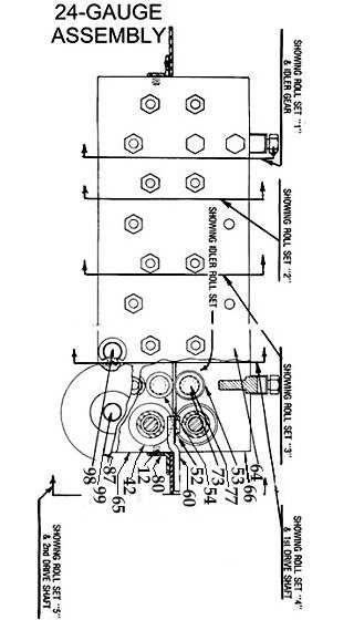
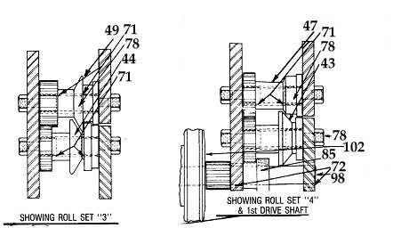
9 9 PARTS LIST AND DESCRIPTION Parts For 24 Gauge Pitts Fine No. Part No. Description No. REQ"D. 1 24P66040 Bearing Idler Roll 2 24P #9 Woodruff Key P Key 4.76 SQ. x 38.1 mm P Cord 14-3 x 10 Ft P /2 Hp P Toggle Switch P Sta. Kon Connector B P BX Connector ½ P Insulating Cap P Wire Joint P Gauge Dial P Hex Bolt M x 15 mm P Hex Bolt M x 50 mm P Hex Bolt M x 20 mm P Hex Socket Set Screw M x 10 mm P Hex Socket Set Screw M x 10 mm P Hex Socket Set Screw M6-1 x 10 mm P Drive Screw x mm P Thumb Screw M x 25 mm P Phillips Head Stove Bolt M6-1 x 15 mm P Hex Socket Set Screw M x 10 mm P Phillips Head Stove Bolt M x 20 mm P Hex Bolt M mm P Hex Nut M P Jam Nut M P Lock Nut M P Lock Washer 10 mm P Steel Washer x mm P Washer x mm P Lock Washer 8 mm P Brs. Washer x mm P Washer 8 x mm P Dowel Pin x mm P Dowel Pin x 38.1 mm P Dowel Pin x mm P Spring Compression P Compression Spring 3/8 ID P L 500 Belt P Name Plate P Lf. Cap Name Plate P Logo P Bottom Forming Roll B5 1
10 43 24P Bottom Forming Roll B P Bottom Forming Roll B P Bottom Forming Roll B P Bottom Forming Roll B P Top Forming Roll T4 &T P B Top Forming Roll T P Top Forming Roll T P Top Forming Roll T P Top Forming Roll T P Opening Roll P Upper Idler Roll (need 1 B812 Tor) P Lower Idler Roll (need 1 B812 Tor) P Knurled Forming Roll P Plain Forming Roll P Inner Race Assembly P Adjustable Guide Roll P Sensory Casting P Opening Roll Hldr Assbly/ EXIT GUIDE BAR P Feed Gauge Bar P Compensator Arm P Tension Spring Push Rod P Back Housing Plate P Lower Front Housing Plate P Upper Front Housing Plate P Stand Assembly P Toggle Switch Plate P Cast Iron Base P Spacer Plate P Bearing B1012 Torr P Bearing B128 Torr P Bearing B812 Torr P Bearing B108 Torr P Bearing P Forming Table P Idler Roll Pin P Spacer Stud P Woodruff Key Modified P Machine Support P Bracket Cast P Cover Assembly P Cover P Removable Cover P Thrust Collar P Collar mm P Gear Driven with Hub P Gear Bevel P Gear Comb. Spur & Bevel 1 10
11 90 24P Gear P Steel Forming Head P Special Machine Key -Concave P Tension Screw Nut M P Lifter Plug P Spacer P Spacer Step P Tension Screw M P st Drive Shaft w/integral Gear P nd Drive Shaft w/integral Gear P Idler Gear (need 1 B128 Tor) P P Spacer Stud Roll Shaft P Sheave Machine 9-1/ P A5 23 5/8 Sheave P Hex Bolt M x 40 mm P GA (no Flanger Cover) 11 TO INSTALL POWER FLANGING ATTACHMENT 1. Remove top cover by removing the two hold-down studs and lifting the cover from the machine. 2. Replace the two hold-down studs and adjust. 3. Set the flanging attachment over the forming head so that the combination bevel and spur gear meshes with the Pittsburgh Lock roll No Place the two 3/8 x 11/4 Hex-Head cap screws and lock washers into flanging attachment mounting holes and tighten. TO OPERATE POWER FLANGING ATTACHMENT
12 12 ADJUST UNIT FOR GAUGE MATERIAL TO BE USED To adjust clearance between flanging rolls, tighten the adjusting screw on the front of the block of the machine all the way, then loosen the screw approximately one eighth of a turn. (This setting is usually correct for 26 gauge material.) Do not set front gauge adjusting screw too tight. It should be set just tight enough to draw the metal through the rolls. Too tight a setting will stretch and wrinkle the material. To adjust the spring tension on the compensator arm, tighten the adjusting dial on the backside of the flanger to the stop and then turn back to the proper gauge setting shown on the adjusting dial. TURN UP A STARTING FLANGE on the material before inserting it into leading edge of the work to be flanged in the slot cut into the table and bending the piece away from the operator approximately 45 degrees. Start the leading edge of the material into the rolls. As the material passes through the rolls, the compensator arm will make contact with the material and guide it through the rolls. If the material pulls out of the rolls, it is an indication that either the front adjusting screw is too loose or the back adjusting dial is not tight enough. IMPORTANT. When starting a partially formed section that contains an inside curve, push the compensator arm back until it locks out of position. Feed partially formed section into the rolls and the machine will pull the material through. As the rolls approach the section that is not formed, bring the compensator arm to the material holding the spring tension off the piece until the unformed section comes to the rolls; then bear pressure to the piece until the flange picks up, then release compensator arm so that automatic guiding is resumed.

13 13
TO OPERATE AUTO-GUIDE POWER. 24 Gauge Pittsburgh Operating Instructions FLANGING ATTACHMENT
 24 Gauge Pittsburgh Operating Instructions Holding the material against the angle gauge slide it into the forming head. Be sure that the material remains against the gauge until work is finished. Make
Operating Instructions
 Operating Instructions Holding the material against the angle gauge slide it into the forming head. Be sure that the material remains against the gauge until work is finished. NOTE: This machine will handle
TIN KNOCKER TK 1660 DUCT BEADER
 TIN KNOCKER TK 660 DUCT BEADER Sheet Metal Equipment Sales Inc. Dean P. O'Connell, President Green Bay, Wisconsin Phone - (90)-66-9966 Fax - (90)-66-9969 06/04/004 Website: www.sheetmetalequip.com TIN
Operating Instructions For Lockformer Button Punch Flanger
 Capacity: 20 to 28 Gauge Galvanize Operating Instructions For Lockformer Button Punch Flanger To satisfactorily form the 90º button punch flange on light gauge materials, it was necessary to form the metal
TK 1014 A POWER SHEAR
 TIN KNOCKER TK 1014 A POWER SHEAR Parts Diagram & Operating Instructions TAAG INDUSTRIES CORP. 1550 SIMPSON WAY, ESCONDIDO, CA 92029 Tel: (800) 640-0746 Fax: (760) 727-9948 Website: www.tinknocker.com
TIN KNOCKER TK 1624 SLITTER INSTRUCTIONS & PARTS DIAGRAM. Shown with Optional Stand
 1 TIN KNOCKER TK 1624 SLITTER INSTRUCTIONS & PARTS DIAGRAM Shown with Optional Stand TAAG MACHINERY CO. (Master Distributor) 1257-B Activity Dr. Vista, CA 92081 Tel: (800) 640-0746 Fax: (760) 727-9948
TK 422 PORTABLE BRAKE
 1 TIN KNOCKER TK 422 PORTABLE BRAKE INSTRUCTIONS & PARTS DIAGRAM TAAG MACHINERY CO. (Master Distributor) 1257-B Activity Dr. Vista, Ca 92081 Tel: (800) 640-0746 Fax: (760) 727-9948 Website: www.tinknocker.com
TIN KNOCKER TK NO. 24 CHEEK BENDER INSTRUCTIONS & PARTS DIAGRAM. TK No. 24 CHEEK BENDER
 1 TIN KNOCKER TK NO. 24 CHEEK BENDER INSTRUCTIONS & PARTS DIAGRAM TK No. 24 CHEEK BENDER Sheet Metal Equipment Sales Inc. Dean P. O'Connell, President Green Bay, Wisconsin Phone - (920)-662-9966 Fax -
TIN KNOCKER TK 2248 BOX & PAN BRAKE INSTRUCTIONS & PARTS DIAGRAM TK 2248 BOX & PAN BRAKE
 TIN KNOCKER 1 TK 2248 BOX & PAN BRAKE INSTRUCTIONS & PARTS DIAGRAM TK 2248 BOX & PAN BRAKE Sheet Metal Equipment Sales Inc. Dean P. O'Connell, President Green Bay, Wisconsin Phone - (920)-662-9966 Fax
TABLE OF CONTENTS DESCRIPTION. Safety Instructions Assembly Operation... 7
 TABLE OF CONTENTS DESCRIPTION PAGE Warranty... 1 Safety Instructions... 2 Assembly... 3 Operation... 7 #360 Grain Cleaner Drawings... 8 #360 Grain Cleaner Parts List... 10 Utility Auger Option Drawing...
MODEL 83 Pail Handler
 MORSE MFG. CO., INC. 727 West Manlius Street P.O. Box 518 East Syracuse, NY 13057-0518 Phone: 315-437-8475 Fax: 315-437-1029 Email: service@morsemfgco.com Website: www.morsemfgco.com COPYRIGHT 2005 MORSE
TABLE OF CONTENTS DESCRIPTION. Safety Instructions Assembly Operation... 7
 TABLE OF CONTENTS DESCRIPTION PAGE Warranty... 1 Safety Instructions... 2 Assembly... 3 Operation... 7 #360 Grain Cleaner Drawings... 8 #360 Grain Cleaner Parts List... 10 Utility Auger Option Drawing...
Electric Skein Winder
 Electric Skein Winder Assembly and Use Package Contents 1 - Triangular Body (w/ motor) 1 - Cross Arm 1 - Left Foot (w/ yarn guide) 1 - Right Foot 1 - Adjustable Finger (w/ yarn clip) 3 - Adjustable Fingers
PLATINUM SERIES TABLESAW W/DOVETAIL MECH LEFT-TILT MANUAL
 PLATINUM SERIES TABLESAW W/DOVETAIL MECH LEFT-TILT MANUAL LAGUNA TOOLS 2072 Alton Parkway Irvine, California 92606 Ph: 800.234.1976 www.lagunatools.com 2018, Laguna Tools, Inc. LAGUNA and the LAGUNA Logo
JARVIS. Model BR-3 Blade Reconditioner ... EQUIPMENT TABLE OF
 - Model BR-3 Blade Reconditioner EQUIPMENT SELECTION.......... Ordering No. TABLE OF CONTENTS............................ Page Model BR-3 (100 mm Blade) 115V/60Hz............ 4011003 220V/50Hz............
OPERATION & MAINTENANCE MANUAL
 OPERATION & MAINTENANCE MANUAL AUTOMATIC PECAN CRACKER Food Processing Equipment and Machinery Specializing in the Pecan Industry Mailing: PO Box 817, Mansfield, Louisiana 71052 Located: 280 Independence
Tube Facing Tool.
 www.swagelok.com Tube Facing Tool This manual contains important information for the safe and effective operation of the Swagelok TF72 series tube facing tool. Users should read and understand its contents
HOLE CUTTER SHARPENER ASSEMBLY & SERVICE MANUAL
 HOLE CUTTER SHARPENER ASSEMBLY & SERVICE MANUAL WARNING You must thoroughly read and understand this manual before operating the equipment, paying particular attention to the Warning & Safety instructions.
Bead Roller Operating, Servicing, and Safety Instruction Manual
 Bead Roller Operating, Servicing, and Safety Instruction Manual CAUTION: Read and Understand These Operating, Servicing, and Safety Instructions, Before Using This Machine. 1-800-67-26 10 Cooperative Way
400A 40113V, 401A 40120V, & 401AL 40120VL ALUMINUM VERTICAL 4000 LB LIFT INCLUDES SCREW LEG ASSEMBLY INSTRUCTIONS
 12/11/07 PAGE 1 OF 12 400A 40113V, 401A 40120V, & 401AL 40120VL ALUMINUM VERTICAL 4000 LB LIFT INCLUDES SCREW LEG ASSEMBLY INSTRUCTIONS Thank you for purchasing our product! *Please read these instructions
INSTALLATION INSTRUCTIONS
 INSTALLATION INSTRUCTIONS SPORTSMAN WINCH MOUNT GRILLE GUARD APPLICATION: 2016-2018 Toyota Tacoma PART NUMBER: 40-93885, 45-93880, 46-23885 ITEM QUANTITY DESCRIPTION TOOLS NEEDED 1 1 WINCH TRAY 15MM SOCKET
Assembly Instructions
 page 1 Serious personal-injury to the operator or bystanders, as well as damage to equipment or property, can occur, if all safety and assembly instructions, provided with this product, are not followed.
SECTION 9: PARTS. Headstock
 SECTION 9: PARTS We do our best to stock replacement parts when possible, but we cannot guarantee that all parts shown are available for purchase. Call (800) 52-4777 or visit www.grizzly.com/parts to check
No. 412, 414, 416 Operations Manual
 No. 412, 414, 416 Operations Manual CARE: Occasional oiling of moving parts with machine oil will ease operation and extend the life of the brake. Occasionally check and tighten the lower beam bracket
H8508 Impact Wrench SERVICE MANUAL. Model (Serial Code FWN) Model (Serial Code FWP)
 Model (Serial Code FWP)") SERVICE MANUAL H8508 Impact Wrench Model 48755 (Serial Code FWN) Model 48760 (Serial Code FWP) Read and understand all of the instructions and safety information in this manual before operating or servicing
SERVICE MANUAL H8508 Impact Wrench Model 48755 (Serial Code FWN) Model 48760 (Serial Code FWP) Read and understand all of the instructions and safety information in this manual before operating or servicing
SECTION 9: PARTS. Headstock A 126A 127A-1 REF PART # DESCRIPTION REF PART # DESCRIPTION
 SECTION 9: PARTS Headstock 120 121 113 115 112 111 110 109 108 105 106 107 135 101 119A 121 120 118 114 115 107 106 104 123 122 118 114 126A 105 126 103 102 126B 127A-1 131 127A 124 133 134 126C 129 130
SECTION 9: PARTS. G7947 Stand & Table Breakdown 4V2
 SECTION 9: PARTS G7947 Stand & Table Breakdown 19 15 21 18 16 17 112 5 113 3 14 8 7 6 6-1 13 4V2 12 116 11 9 10 2 114 115 1 We do our best to stock replacement parts when possible, but we cannot guarantee
G0513X2 Main -87- G0513 Series Bandsaws 82V V2 82-6V2 95A V2 82-5V2 82-1V2 82-4V V A
 G0513X2 Main 23 55 22 48 17 17-1 17-2 21 7 17-3 17-2 17-4 24 17-5 18-5 22 24 21 55A 50 8 9 49 11 12 13 14 15 47 16 10 46 45 3 44 43 39 38 37 39 40 32 33 36 42 34 35 2 25 28 18-4 18-2 18-3 31 30 29 18-1
G0513X2 Main. G0513 Series Bandsaws (Mfd. Since 07/18) A V2
 A V2") G0513X2 Main 55 17 48 7 16 55A 14 15 49 13 47 50 12 10 71 70 72 73 59 69 74 46 11 9 8 76 5 75 4 68 81 80 67 66 48 50 39 78 79 23 17-3 17-2 17-1 17-4 17-2 21 22 24 17-5 32 33 34 35 28 2 45 3 38 44 39 43
G0513X2 Main 55 17 48 7 16 55A 14 15 49 13 47 50 12 10 71 70 72 73 59 69 74 46 11 9 8 76 5 75 4 68 81 80 67 66 48 50 39 78 79 23 17-3 17-2 17-1 17-4 17-2 21 22 24 17-5 32 33 34 35 28 2 45 3 38 44 39 43
SERVICE MANUAL AND PARTSLIST
 SERVICE MANUAL AND PARTSLIST Next 20 CONTENTS WHAT TO DO WHEN... 1~3 SERVICE ACCESS FACE COVER... 4 TOP COVER... 4 BASE COVER... 5 REAR COVER... 6 FRONT COVER... 7 MECHANICAL ADJUSTMENT NEEDLE THREAD TENSION...
Parts Catalog. S-Series Slicer Manual Frozen Option S13. Model:
 , 07 995 ECN 08 Parts Catalog S S-Series Slicer Manual Frozen Option Model: S 05/0/07 Rev. G IMPORTANT! TO EXPEDITE SHIPMENT OF PARTS, ALWAYS SPECIFY MODEL, REV, PART NUMBER, AND SERIAL NUMBER OF UNIT.
ET-110 EXTREMA MACHINERY COMPANY, INC. P.O. BOX 1450, ALBANY, LOUISIANA (877) FAX (225)
 FAX (225)") ET-0 EXTREMA MACHINERY COMPANY, INC. P.O. BOX 450, ALBANY, LOUISIANA 707 (877) 398-7362 FAX (225) 567-2966 PREFACE The XT-0 is precision built and manufactured to satisfy the highest standards. For maximum
ET-0 EXTREMA MACHINERY COMPANY, INC. P.O. BOX 450, ALBANY, LOUISIANA 707 (877) 398-7362 FAX (225) 567-2966 PREFACE The XT-0 is precision built and manufactured to satisfy the highest standards. For maximum
INSTRUCTION MANUAL AND PARTS LIST MODEL 14-10
 VERTICAL BAND SAWS INSTRUCTION MANUAL AND PARTS LIST MODEL 1-10 DAKE/PARMA WHEN ORDERING PARTS GIVE COMPLETE SERIAL NUMBER OF MACHINE GIVE PART NUMBER AND NAME GIVE AMOUNT REQUIRED Unless the above data
ELECTRIC SLIP ROLL MACHINE. Model: ESR-1300X2.5/ESR-1300X4.5 ESR-1550X3.5/ESR-1580X2.0
 ELECTRIC SLIP ROLL MACHINE Model: ESR-1300X2.5/ESR-1300X4.5 ESR-1550X3.5/ESR-1580X2.0 Operation Manual Table of contents I MAIN SPECIFICATION...2 II SAFETY INSTRUCTIONS.. 2 III OPERATION INSTRUCTIONS..4
RYOBI 10 in. TABLE SAW - MODEL NO. BT3000
 FOR MITER TABLE ASSEMBLY, REFER TO FIGURE 0 RYOBI 0 in. TABLE SAW - MODEL NO. BT000 FIGURE 5: 0 in. TABLE SAW FOR BLADE GUARD ASSEMBLY, REFER TO FIGURE FOR RIP FENCE ASSEMBLY, REFER TO FIGURE FOR MOTOR
SECTION 9: PARTS Main
 SECTION 9: PARTS Main 58 63 67 66 65 67 66 59 58 49 58 48 49 61A 61 64 62 55 50 35-3 34 35-1 57 56 41 42 151 51 50 33A 35-2 30A 30A-1 35 38 39 31 32 18 40 43 44 68 51 41 45 46 57 56 55 47 152 153 20 21
3200 Series Modular Belt Straight Conveyors
 00 Series Modular Belt Straight Conveyors Installation, Maintenance and Parts Manual Flat Modular Belt Conveyor Modular Belt Z-Frame Conveyor Available with: DORNER MFG. CORP. INSIDE THE USA OUTSIDE THE
Horizontal and Vertical. Metal Cutting Band Saw MODEL: BS-115
 Horizontal and Vertical Metal Cutting Band Saw MODEL: BS-5 SAFETY. Know your band saw. Read the operator s Manual carefully. Learn the operations, applications and limitation.. Use recommended accessories.
th St N Oak Park Heights, MN Phone: Fax:
 12430 55 th St N Oak Park Heights, MN 55082 Phone: 651.342.1756 Fax: 651.342.1293 Email: info@diacro.com SAFETY INFORMATION PG. 3 MAINTENANCE PG. 3 #4 BENDER BREAKDOWN AND PARTS LIST PG. 4-6 QUIK-LOK BREAKDOWN
Hydraulic Clamp Carrier. Installation & Operation Manual
 Hydraulic Clamp Carrier Installation & Operation Manual Hydraulic Clamp Carrier Installation & Operation Manual Quick Machinery Company 8272 Peninsula Drive Kelseyville, CA 95451 phone: (707) 272-6719
LSU Duct Liner Sizer. LSU Duc DUCT LINER SIZER MACHINERY DIVISION OWNER S MANUAL
 LSU Duct Liner Sizer LSU Duc DUCT LINER SIZER OWNER S MANUAL MACHINERY DIVISION ASSEMBLY INSTRUCTIONS IMPORTANT: DO NOT TIGHTEN THE NUTS UNTIL THE UNIT IS COMPLETELY ASSEMBLED. A) Assemble the cutting
Please read BOTH these Installation Instructions and the General Instructions prior to installing or operating this equipment.
 2012-15 Hyundai Accent GLS/SE (With Foglights) Attachment Tab Height: 14 Serial Number Attachment Tab Width: 24 Please read BOTH these and the General Instructions prior to installing or operating this
A-dec 574L and 575L Dental Lights on a Cabinet or Wall INSTALLATION GUIDE
 A-dec 574L and 575L Dental Lights on a Cabinet or Wall INSTALLATION GUIDE A-dec 574L Dental Light Mounted on an A-dec Inspire TM 59 Central Console Before You Begin. Turn off the power to the system before
RESIDENTIAL MOTORIZED STORAGE UNIT
 BY V-BRO PRODUCTS RESIDENTIAL MOTORIZED STORAGE UNIT Model: GGR220 INSTALLATION AND OPERATING INSTRUCTIONS Distributed Exclusively by V-BRO PRODUCTS For technical questions and replacement parts, please
LSU Duct Liner Sizer. LSU Duct UCT LINER SIZER MACHINERY DIVISION OWNER S MANUAL
 LSU Duct Liner Sizer LSU Duct LDUC UCT LINER SIZER OWNER S MANUAL MACHINERY DIVISION assembly Instructions IMPORTANT: DO NOT TIGHTEN THE NUTS UNTIL THE UNIT IS COMPLETELY ASSEMBLED. A) Assemble the cutting
WARNING. BX Ford Explorer With Adaptive Cruise Control & Eco Boost Installation Instructions
 Please read BOTH these and the General Instructions before attempting to install or operate this equipment. 1. Blue Ox towing products and accessories are intended to be installed by Blue Ox Dealers who
Dear Woodworker: Thank you for your purchase and welcome to the Laguna Tools group of discriminating woodworkers. I understand that you have a choice
 Platinum Series Tablesaw w/ Dovetail Mech Left-tilt Manual 17101 Murphy Avenue, Irvine, CA 92614 www.lagunatools.com 800.234.1976 MTS0300-0180 1 Table saw Dear Woodworker: Thank you for your purchase and
A-dec 6300 Ceiling-Mount Dental Light INSTALLATION GUIDE
 A-dec 6300 Ceiling-Mount Dental Light INSTALLATION GUIDE Recommended Tools Hex key set Plumb bob Drill 3/16" drill bit 6' piece of tubing Level Phillips head screwdriver Tape measure Anti-static strap
Owner s Manual ODYSSEY BENCH MODEL. O4100B shown REV E. Southern Avenue, Phoenix, AZ USA Workhorseproducts.
 Owner s Manual ODYSSEY BENCH MODEL O4100B shown 67-1375 REV 218 3730 E. Southern Avenue, Phoenix, AZ 85040 USA 800-778-8779 Workhorseproducts.com 1 Table of Contents I. Introduction & Safety Information.
HD installation guide
 JANUS INTERNATIONAL 1 866 562 2580 www.janusintl.c o m 1950 1950HD installation guide RIGHT DRIVE END SHOWN LH OPPOSITE LEFT TENSION END SHOWN RH OPPOSITE PUSH-UP OPERATION 1950 1950HD SHOWN A rolling
Geology, Prospectors, Mining, Metallurgy, Assaying, Environmental, Geotechnical
 LEGEND INC. Geology, Prospectors, Mining, Metallurgy, Assaying, Environmental, Geotechnical 988 Packer Way Sparks, NV 89431 Tel: (786) 786-3003 Fax: (775) 786-3613 Email: info@lmine.com Web: www.lmine.com
Inventory (Figure 2)
") MODEL T10127 12" SPIRAL CUTTERHEAD INSTRUCTIONS The Model T10127 indexable insert spiral cutterhead is designed to replace the straightknife cutterhead from the Grizzly jointer Model G0609. The total procedure
MODEL T10127 12" SPIRAL CUTTERHEAD INSTRUCTIONS The Model T10127 indexable insert spiral cutterhead is designed to replace the straightknife cutterhead from the Grizzly jointer Model G0609. The total procedure
RPS /02 Effective for models with serial numbers beginning with "G".
 Instruction Sheet B2000 Cyclone Bender RPS-0097 0/02 Effective for models with serial numbers beginning with "G". IMPORTANT RECEIVING INSTRUCTIONS Visually inspect all components for shipping damage. If
SECTION 9: PARTS Main Breakdown
 SECTION 9: PARTS Main Breakdown 2 115 75 113 112 8 9 7 8 11 4 5 3 3 85 81 79 78 90 84 68 69 69 68 87 86 86 91 95 98-2 98-1 98-3 98-4 98 98-8 98-9 98-5 98-6 99 97 98-7 100 92 114 108 107 110 109 111 104
Parts Catalog. S-Series Slicer Smart Manual SG13. Model:
 , 07 99507 ECN 065 Parts Catalog S-Series Slicer Smart Manual Model: SG SG 0/0/07 Rev. G IMPORTANT! TO EXPEDITE SHIPMENT OF PARTS, ALWAYS SPECIFY MODEL, REV, PART NUMBER, AND SERIAL NUMBER OF UNIT. GLOBE
HYDRAULIC CONTROL DETAILS PARTS LIST
 Always give model number, serial number and part number when ordering repair parts. HYDRAULIC CONTROL DETAILS PARTS LIST REF NO. PART NUMBER DESCRIPTION 1 101939 Hydraulic Tank 2 101940 Hydraulic Tank
MODEL 36 Di-Acro Hand Shear
 OPERATOR S MANUAL & INSTRUCTIONS MODEL 36 Di-Acro Hand Shear Di-Acro, Incorporated PO Box 9700 Canton, Ohio 44711 3713 Progress Street N.E. Canton, Ohio 44705 330-455-1942 330-455-0220 (fax) Revised 01/02
Continuum Frame Assembly Instructions
 Continuum Frame Assembly Instructions Copyright January 1, 2017 Jim M. Bagley, GraceWood, Inc (Reproduction Prohibited) Version 2.2 Table of Contents Continuum Frame Table of Contents... i Warranty...ii
Astro-Physics Inc. 400QMD Lubrication/Maintenance Guide
 Astro-Physics Inc. 400QMD Lubrication/Maintenance Guide The following guidelines should be followed to lubricate the three main parts of the 400QMD mount. The QMD stands for Quartz Micro-Drive controller.
installation guide
 JANUS INTERNATIONAL 1 866 562 2580 w w w. j a n u s i n t l. c o m 2000 2500 3000 installation guide RIGHT DRIVE END SHOWN LH OPPOSITE LEFT TENSION END SHOWN RH OPPOSITE PUSH-UP OPERATION 2000 2500 3000
INSTALL INSTRUCTIONS WELCOME TO THE NEWAGE PERFORMANCE CABINETRY SERIES NEWAGE STEEL WELDED CABINETRY
 NEWAGE STEEL WELDED CABINETRY WELCOME TO THE NEWAGE PERFORMANCE CABINETRY SERIES ALL CABINETS MUST BE MOUNTED TO STUDS ON A SECURE WALL, AS PER THESE INSTRUCTIONS. FAILURE TO DO SO MAY RESULT IN SERIOUS
MODEL G0759 MILL/DRILL w/stand & DRO MANUAL INSERT
 MODEL G0759 MILL/DRILL w/stand & DRO MANUAL INSERT The Model G0759 is the same machine as the Model G0704 except the Model G0759 has a 3-axis DRO. Besides the differences noted in this insert, all other
MODEL T " HELICAL CUTTERHEAD INSTALLATION INSTRUCTIONS
 MODEL T27696 12" HELICAL CUTTERHEAD INSTALLATION INSTRUCTIONS For questions or help with this product contact Tech Support at (570) 546-9663 or techsupport@grizzly.com Introduction The Model T27696 indexable
Please read BOTH these Installation Instructions and the General Instructions prior to installing or operating this equipment.
 Attachment Tab Height: 16-1/2 Serial Number Attachment Tab Width: 24 Please read BOTH these and the General Instructions prior to installing or operating this equipment. 1. Blue Ox towing products and
LC200DS2 Double Stud Dual Articulating Wall Mount for Flat Panel Screens up to 32" with up to 200mm x 200mm VESA Mounting Patterns
 LC200DS2 Double Stud Dual Articulating Wall Mount for Flat Panel Screens up to 32" with up to 200mm x 200mm VESA Mounting Patterns Multi-position triple pivoting arms allows you to position the monitor
Sales and Service
 OPERATION MANUAL / SPARE PARTS LIST MANUAL SEALLESS STEEL STRAPPING TOOL MODEL A333 13.2370.01 INDEX PAGE 1 SAFETY INSTRUCTIONS 2 2 WARRANTY CONDITIONS AND LIABILITY 3 3 APPROPRIATE USE 3 4 TECNICAL DATA
INSTALLATION INSTRUCTIONS HEAVY DUTY TILT WALL MOUNT Model: PPH-2000
 INSTALLATION INSTRUCTIONS HEAVY DUTY TILT WALL MOUNT Model: PPH-2000 Specifications: Accomodates Akira and Orion 84" displays without interface bracket; accomodates other large flat panel displays with
SawStop. Contractor Fence Assembly OWNER S MANUAL. Model CNS-SFA
 Contractor Fence Assembly OWNER S MANUAL Model CNS-SFA Warranty warrants to the original retail purchaser of the Contractor Fence Assembly accompanying this manual that the fence assembly will be free
Operation, Parts and Maintenance Manual Model Notcher
 Operation, Parts and Maintenance Manual Model 16-18 Notcher 6926 Smithville Hwy. McMinnville, TN 37110 Phone: 931-934-2211 Fax: 931-934-2220 Email info@tennsmith.com www.tennsmith.com Proudly Made in the
INSTRUCTION BOOK AND PARTS LIST
 Rag Cutter MODEL WE WARNING This machine is equipped with a very sharp knife. Keep hands, arms, and hair away from the knife area at all times. Misuse of this machine or failure to follow all safety instructions
2300 Series DustPruf End Drive Conveyors
 00 Series DustPruf End Drive Conveyors Installation, Maintenance and Parts Manual Featuring: DORNER MFG. CORP. INSIDE THE USA OUTSIDE THE USA P.O. Box 0 975 Cottonwood Ave. TEL: -800-97-866 TEL: 6-67-7600
SECTION 9: PARTS Main
 63 58 62 61A 66 65 67 66 67 58 58 59 64 SECTION 9: PARTS 162 161 Main 160 45 152 21 20 17 153 166 33 30A 31 32 135 144 133 136 34 35-2 35-3 131 16 130 134 139 15 35-1 137 14V2 151 140 38 143 150 18 142
2200 Series End Drive Conveyors
 00 Series End Drive Conveyors Installation, Maintenance & Parts Manual DORNER MFG. CORP. INSIDE THE USA OUTSIDE THE USA P.O. Box 0 975 Cottonwood Ave. TEL: -800-97-866 TEL: 6-67-7600 Hartland, WI 509-000
25-200H. 12 Planer / Jointer. with Helical Cutterhead. Parts List.
 25-200H 12 Planer / Jointer with Helical Cutterhead 4001824 Parts List www.rikontools.com CABINET ASSEMBLY PARTS EXPLOSION & PARTS LIST KEY NO. DESCRIPTION KEY NO. DESCRIPTION 1 Pan Head Screw M6x12 P25-200H-1
LC200DS1 Double Stud Articulating Wall Mount for Flat Panel Screens up to 32" with up to 200mm x 200mm VESA Mounting Patterns
 Page 1 of 6 LC200DS1 Double Stud Articulating Wall Mount for Flat Panel Screens up to 32" with up to 200mm x 200mm VESA Mounting Patterns A multi-position dual articulating arm for flat screens up to 60
Please read BOTH these Installation Instructions and the General Instructions prior to installing or operating this equipment.
 Attachment Tab Height: 19-1/2 Attachment Tab Width: 19 Serial Number Please read BOTH these and the General Instructions prior to installing or operating this equipment. 1. Blue Ox towing products and
Tire Chain Kit. Replacing Shear Pins. Weight Kits. Drift Cutter
 Replacing Shear Pins The augers are secured to the spiral shaft with two shear pins and cotter pins. If the auger should strike a foreign object or ice jam, the snow thrower is designed so that the pins
M2 Assembly. M2 Sub-Assemblies mm Belt Sub-Assembly mm Belt Sub-Assembly Spider Sub-Assembly... 4
 M2 Assembly Table of Contents M2 Sub-Assemblies... 3 630mm Belt Sub-Assembly... 3 702mm Belt Sub-Assembly... 3 Spider Sub-Assembly... 4 Idler Bolt Sub-Assembly... 8 Y Motor Sub-Assembly... 9 X Motor Sub-Assembly...
VARIABLE SPEED WOOD LATHE. Model DB900 INSTRUCTION MANUAL
 VARIABLE SPEED WOOD LATHE Model DB900 INSTRUCTION MANUAL 1007 TABLE OF CONTENTS SECTION...PAGE Technical data.. 1 General safety rules....1-3 Specific safety rules for wood lathe.....3 Electrical information.4
OPERATOR'S MANUAL 46" SNOW BLADE. Model Numbers OEM IMPORTANT: READ SAFETY RULES AND INSTRUCTIONS CAREFULLY
 OPERATOR'S MANUAL 46" SNOW BLADE Model Numbers 190-833-OEM IMPORTANT: READ SAFETY RULES AND INSTRUCTIONS CAREFULLY MTD PRODUCTS INC. P.O. BOX 368022 CLEVELAND, OHIO 44136-9722 PRINTED IN U.S.A. FORM NO.
Dual Arm Tilt LCD Mount
 Installation Manual model # 51324 M o u n t i n g S y s t e m s Dual Arm Tilt LCD Mount Fits Displays 13 to 32 Supports Up to 50 lbs (23 kgs) Projection from Wall from 3 to 17 Meets VESA Standards 50/75/100,
RYOBI 10 in. (254 mm) TABLE SAW MODEL NO. BT3100 REPAIR SHEET
 TABLE SAW MODEL NO. BT3100 REPAIR SHEET") RYOBI 0 in. (4 mm) TABLE SAW MODEL NO. BT00 REPAIR SHEET FOR MITER TABLE ASSEMBLY, REFER TO FIGURE B FOR BLADE GUARD ASSEMBLY, REFER TO FIGURE E FOR RIP FENCE ASSEMBLY, REFER TO FIGURE C FOR MOTOR ASSEMBLY,
RYOBI 0 in. (4 mm) TABLE SAW MODEL NO. BT00 REPAIR SHEET FOR MITER TABLE ASSEMBLY, REFER TO FIGURE B FOR BLADE GUARD ASSEMBLY, REFER TO FIGURE E FOR RIP FENCE ASSEMBLY, REFER TO FIGURE C FOR MOTOR ASSEMBLY,
MODEL M1023 QUICK CHANGE COLLET ATTACHMENT INSTRUCTION MANUAL. Phone: On-Line Technical Support:
 MODEL M1023 QUICK CHANGE COLLET ATTACHMENT INSTRUCTION MANUAL Phone: 1-360-734-3482 On-Line Technical Support: tech-support@shopfox.biz #6727BL COPYRIGHT JANUARY, 2005 BY WOODSTOCK INTERNATIONAL, INC.
LEG CURL IP-S1315 INSTALLATION INSTRUCTIONS
 LEG CURL IP-S35 INSTALLATION INSTRUCTIONS Copyright 2009. Star Trac by Unisen, Inc. All rights reserved, including those to reproduce this book or parts thereof in any form without first obtaining written
MODEL H " BYRD SHELIX CUTTERHEAD INSTRUCTIONS
 MODEL H9291 12" BYRD SHELIX CUTTERHEAD INSTRUCTIONS The Model H9291 12" Byrd Shelix cutterhead is designed to replace the straight-knife cutterhead on the Grizzly jointer Model G0609. The total procedure
WARNING Honda CR-V Honda Element Installation Instructions BX2232. Serial Number
 Please read BOTH these and the General Instructions before attempting to install or operate this equipment. 1. Blue Ox towing products and accessories are intended to be installed by Blue Ox Dealers who
Please read BOTH these Installation Instructions and the General Instructions prior to installing or operating this equipment.
 Attachment Tab Height: 13 Attachment Tab Width: 24 Please read BOTH these and the General Instructions prior to installing or operating this equipment. Serial Number 1. Blue Ox towing products and accessories
VARIABLE SPEED WOOD LATHE
 MODEL MC1100B VARIABLE SPEED WOOD LATHE INSTRUCTION MANUAL Please read and fully understand the instructions in this manual before operation. Keep this manual safe for future reference. Version: 2015.02.02
Inventory MODEL H7937 TAPER ATTACHMENT FOR THE G0600 LATHE INSTRUCTIONS. Inventory (Figure 1) Needed Items
 Needed Items") MODEL H7937 TAPER ATTACHMENT FOR THE G0600 LATHE INSTRUCTIONS Inventory The Model H7937 taper attachment was carefully packed when it left our warehouse. If you discover it is damaged after you have signed
MODEL H7937 TAPER ATTACHMENT FOR THE G0600 LATHE INSTRUCTIONS Inventory The Model H7937 taper attachment was carefully packed when it left our warehouse. If you discover it is damaged after you have signed
Model Assembly & Operating Instructions
 30 SHEAR BRAKE ROLL Model 05907 Assembly & Operating Instructions Diagrams within this manual may not be drawn proportionally. Due to continuing improvements, actual product may differ slightly from the
RYOBI. 10 in. (254 mm) TABLE SAW MODEL NO. BTS15 REPAIR SHEET
 TABLE SAW MODEL NO. BTS15 REPAIR SHEET") RYOBI 0 in. ( mm) TABLE SAW MODEL NO. BTS REPAIR SHEET FIGURE A 0 0 0 0 The model number will be found on a plate attached to the motor housing. Always mention the model number in all correspondence regarding
RYOBI 0 in. ( mm) TABLE SAW MODEL NO. BTS REPAIR SHEET FIGURE A 0 0 0 0 The model number will be found on a plate attached to the motor housing. Always mention the model number in all correspondence regarding
RYOBI 10 IN (254 MM) TABLE SAW MODEL NO. BT REPAIR SHEET
 TABLE SAW MODEL NO. BT REPAIR SHEET") RYOBI 0 IN (2 MM) TABLE SAW MODEL NO. BT00- REPAIR SHEET 2 RYOBI 0 in. (2 mm) TABLE SAW - MODEL NO. BT00- FOR MITER TABLE ASSEMBLY, REFER TO FIGURE B FOR BLADE GUARD ASSEMBLY, REFER TO FIGURE E FOR RIP
RYOBI 0 IN (2 MM) TABLE SAW MODEL NO. BT00- REPAIR SHEET 2 RYOBI 0 in. (2 mm) TABLE SAW - MODEL NO. BT00- FOR MITER TABLE ASSEMBLY, REFER TO FIGURE B FOR BLADE GUARD ASSEMBLY, REFER TO FIGURE E FOR RIP
Please read BOTH these Installation Instructions and the General Instructions prior to installing or operating this equipment.
 Please read BOTH these and the General Instructions prior to installing or operating this equipment. 1. Blue Ox towing products and accessories are intended to be installed by Blue Ox Dealers who are familiar
Motorized M3 AX7200 Rotary-Style Gasket Cutter Operating Instructions
 Motorized M3 AX7200 Rotary-Style Gasket Cutter Operating Instructions INTRODUCTION Congratulations! You are the owner of the finest rotary-style gasket cutter in the world. Originally developed and patented
SM-RAZOR-ART2-L / SM-RAZOR-ART2-XL
 SM-RAZOR-ART2-L / SM-RAZOR-ART2-XL Strong Razor Series Articulating Mount for Large and Extra Large Displays INSTRUCTION MANUAL Installation Manual Warnings: Installation of this product should be done
MPA-9000 Universal Ceiling Projector Mount Kit
 I N S T R U C T I O N M A N U A L Universal Ceiling Projector Mount Kit The Universal Ceiling Projector Mount provides a unique, simplified method of ceiling mounting your inverted projector. This low
MM340 Installation Instructions IMPORTANT SAFETY INSTRUCTIONS - SAVE THESE INSTRUCTIONS
 MM30 Installation Instructions IMPORTANT SAFETY INSTRUCTIONS - SAVE THESE INSTRUCTIONS Please read this entire manual before you begin. Do not unpack any contents until you verify all requirements on PAGE.
PFT CABLE GYM INSTRUCTION MANUAL
 PFT CABLE GYM INSTRUCTION MANUAL QUESTION? As a quality home gym supplier we are committed to your complete satisfaction. If you have questions, or find missing or damaged parts, we will guarantee your
TURBO DRIVE INSTALLATION MODEL 1582T KNEE FEED Lagun Mill
 TURBO DRIVE INSTALLATION MODEL 1582T KNEE FEED Lagun Mill NOTE This Turbo Drive Knee Feed is configured for mounting the feed on the front of the knee with the keypad facing left. The lead screw pitch
WARNING. Bolt Torque Specifications Torque in Foot-Pounds for Inch Bolts Bolt Size Grade 5 Grade 8
 1. Blue Ox towing products and accessories are intended to be installed by Blue Ox Dealers who are familiar with our products and have the equipment and knowledge necessary to do fit work. If needed, Blue