TK 422 PORTABLE BRAKE
|
|
|
- Juniper Cole
- 6 years ago
- Views:
Transcription
 640-0746 Fax: (760) 727-9948 Website: www.tinknocker.com * Email: taag@sbcglobal.net 121306 mod 1")
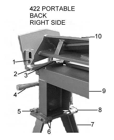
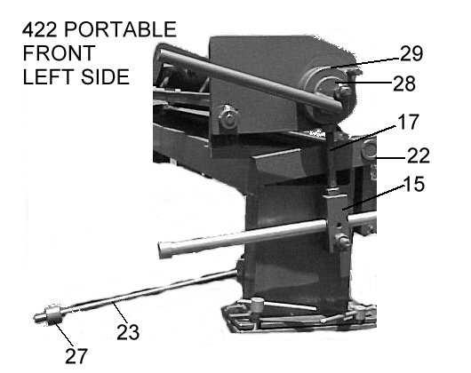
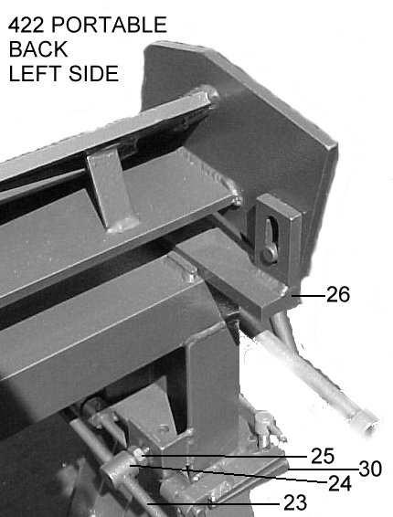
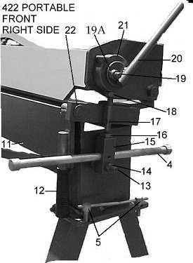
1 1 TIN KNOCKER TK 422 PORTABLE BRAKE INSTRUCTIONS & PARTS DIAGRAM TAAG MACHINERY CO. (Master Distributor) 1257-B Activity Dr. Vista, Ca Tel: (800) Fax: (760) Website: * taag@sbcglobal.net mod 1
2 2 TIN KNOCKER SAFETY RULES TK 422 PORTABLE BRAKE 1. Never use a machine or tool for anything other than its intended purpose. Use the proper tool and equipment for the task. 2. Do not operate the machine in excess of its rated capacity. 3. Never use a pipe or bar on the clamp or bending apron handles for additional leverage. 4. Keep clear of the apron swing area, while operating the brake. WARRANTY All new machines are sold with a one-year limited warranty, on factory defective parts. The warranty is limited to the original user. TAAG Machinery Co. at its option, will repair, replace or refund the purchase price of any part, tool or machine that fails during the warranty period. TAAG Machinery Co. will pay normal shipping charges for replacement parts. After 90 days from date of purchase, all express or overnight delivery charges are the responsibility of the customer. Purchaser must deliver to TAAG Machinery Co., at the address below, any written claim, with proof of original purchase. Replacement parts will be invoiced to purchaser and credit issued when the failed part is delivered to TAAG Machinery Co. Removal, reinstallation or replacement parts shall be at purchasers / user s expense. Failure due to improper use of the machine voids the warranty. NOTE: 1. This machine has been tested and adjusted prior to shipment, but can and often does require readjustment due to vibration and bouncing during transport. Following the procedures described within can easily do readjustment. These are procedures with which you, as a user, should be familiar, as you will use them repeatedly over the life use of the machine. If you have difficulty in performing these procedures, we are here to support you. Call us at: (800) Opening rolls (for Philipsburg Lock) are consumable items and not subject to warranty. TAAG MACHINERY CO. (Master Distributor) 1257-B Activity Dr. Vista, Ca Tel: (800) Fax: (760) Website: * taag@sbcglobal.net


3 3 TK 422 PORTABLE BRAKE, RECEIVING THE MACHINE Inspect before signing Bill of Lading. Upon receipt closely examine the machine for damage during shipment. Any loss or damage should be noted in detail on the delivery receipt and reported to your distributor immediately. Free replacement from TK International is dependent upon the notation and the Bill of Lading or delivery slip. INSTALLING THE MACHINE Locate the Brake in a well-lighted area on a solid, level floor. Be sure you have adequate room to swing both handles and Bending Leaf. PRECAUTIONS DO NOT use the Brake to bend rods, nails or wires. This will cause damage to the edge of the top blade. DO NOT exceed the capacity of the Brake. OPERATING THE TK 422 PORTABLE BRAKE Your brake is a general-purpose tool for bending and forming sheet metal. The brake is operated in the following manner. The 422 Portable s legs are folded and held in place by a chain and c-hook.

4 4 Lifting handles are attached to end of the brake so two men can lift and move the brake where it is needed. Once the brake is where you want it set it down, unhook the chains from the c-hooks and lift the brake. The legs will unfold into place. NOTE: ensure the leg are fully opened and on level ground. Install the Stand Locking Bolts (P/N ) Find number (5) in four places and tighten securely. Pushing the clamp handles toward the rear of the brake lifts the ram from the bed and apron. Insert the material to be bent into the opening between the ram and bed assembly and clamp the material in place by pulling the clamp handles forward. Raise the apron to bend the material to the desired angle. Allowing for metal thickness - The ram assembly must be adjusted to allow for clearance when making bends according to the thickness of the material being formed. This adjustment is made by slightly releasing the clamping pressure on the clamp handles and moving the forward edge back, away from the edge of the clamp block on the bed. This movement is accomplished by loosening the bracket lock bolts (Find Number 5) one on each end of the bed assembly. For 22 gauge materials allow a clearance equal to twice the thickness of the material being worked. For lighter gauges, allow a clearance equal to one and one half times the thickness of the material. A larger bend radius can be accomplished by increasing the clearance. Clamping pressure Clamping pressure should be adjusted according the thickness of the material being worked. A common cause of bending and forming problems is excessive clamping pressure. Clamping pressure should be adequate to hold the material securely in place but not so great as to require undue effort in locking the clamp handles. Clamping pressure is adjusted by turning the nuts on the threaded rod portion of the yoke assembly below the clamp swivel. The lift of the ram assembly is adjusted by turning the nut above the clamp swivel. When the clamping pressure is properly adjusted, lock the nuts against the clamp swivel to prevent any change in adjustment. Capacity The capacity of the brake is 22-gauge mild steel.
5 5 Bending and repeat bends - Bending is accomplished by clamping the work piece under the ram assembly so that the desired line of bend is held at the forward edge of the nose bar and by elevating the apron assembly until the desired degree of bend is obtained. The maximum degree of bend is approximately 140 degrees. Due to the spring back in various materials some overbending may be required to get the desired bend angle. For repeat bends, adjust the stop on the stop rod to limit the swing of the apron assembly. The stop is secured in place with a setscrew. There are four adjustments to do in the following order. Use test strips approximately 2 inch x 3 inch of the same material and thickness you will be forming. You will also need several full lengths or near full-length pieces by about 4 inches wide of the material you are setting up for. Check CLAMPING PRESSURE by placing test strips in the brake about 3 or 4 inches away from each end of brake. Adjust the clamping pressure so that it is at most only enough to keep the material from slipping. It is not desirable to use more clamping pressure. More pressure can pre-load the brake in a way, which will force a distortion. Your best results may be with zero clamping pressure. To change clamping pressure use the nuts at the bottom of the cam assembly stem. RADIUS/SET BACK refers to the distance between the leading edge of the clamp and the inside edge of the apron. Look at your brake from behind. Loosen bolts allowing you to move the clamp forward or back on the table. Now from the front, look at the distance between the leading edge of the clamp and the inside edge of the apron. Move the clamp back from the apron at least 1.5 times the thickness of the material being formed. Be sure to move the clamp back a little too far and then move it forward to take out any slack. Recheck clamping pressure. Be sure clamping pressure is very little or none. Check END TO END CLAMP ALIGNMENT by placing a test strip about 3 or 4 inches from each end of the brake, and bend to approximately 90 degrees. See if they appear to be bent to the same degree. Remove the test strips from the brake and stack one inside the other. Compare the sharpness of the radius. If one test strip is over bent or has a sharper radius, increase the radius set back on the tight end slightly and test again. Here too, you want to be sure move the clamp back a little extra and then bring it forward to take out any slack. TRUSS RODS are adjustable to help make the center of the brake bend the same as the ends. Use truss rods to change the shape of the brake and/or to stiffen it. On models with 2 truss rods on the clamp, you can stiffen the clamp to some degree by pushing with the larger truss and then pulling back with the smaller one. There is a large nut on each of the truss rods, which can add pressure in the center of the clamp, table, or apron. If adjustment is needed, usually the clamp is the place to start. A combination of adjusting the clamp, apron and table truss rods may be needed. After making a change, use the 2 x 3 test strips near the ends of the brake to re-check clamp pressure and end to end alignment, then use a full length strip to see if the middle is
6 6 forming the same as the ends. CAUTION: OVER TIGHTENING TRUSS RODS CAN CAUSE PERMANENT DISTORTION. If, after several tries, you do not get the desired effect, back off pressure on all truss rods and try again with a different sequence. Sometimes a slight upward crown to the table and apron is desirable. When the test strips look right, use the brake normally. If it then changes after using the brake for a while, you ll need to re-adjust. But first see if the set back or end to end alignment changed by using 2 x 3 test strips near each end. After a break-in period, truss adjustment is rarely needed. But you do need to adjust clamp pressure and radius set back for varying gauges. MOST DISTORTIONS ARE DUE TO TOO MUCH CLAMPING PRESSURE & / OR NOT ENOUGH RADIUS SET BACK. When adjusted, a hand brake should form consistently the full length of the brake. Reasonable accuracy is what we are going for here you don t need to get out your protractor and dial gauge. And remember it is necessary to change adjustments when heavier or lighter material is formed. At the least, adjust your brake for the heaviest material you use and leave it there for the lighter material too. OIL APRON PINS, CLAMPING CAMS, & VERTICAL GUIDES BEHIND THE CLAMP FREQUENTLY. There is a block at the bottom of the cam stem where you adjust clamping pressure with the nuts above and below the block. After you adjust clamping pressure, the nuts above the block should be locked against each other so that there is a gap between the block and the nut above the block of about 1/32 to 1/8 (or about.030 to.125). This will allow some movement of the anchor pin/block assembly, which is necessary when only one end of the clamp is opened. Having way too much gap, say ¼ or more, will cause wear on some cam assembly parts and on the anchor pin. Having no gap can cause some cam assembly or vertical guide parts to bind and wear faster. This adjustment should be made whenever you change the gauge of material being formed. At least set it up for the thickest material you normally form with a 1/8 gap above the block. This will leave you room to adjust the nut under the block for some thinner materials without having to adjust the nuts above the block too. During the break in period, clamping pressures is an adjustment that will change with use. Keep in mind that it is important to use correct clamping pressure and minimize the gap above the block at the bottom of the cam stem. It is also very important to avoid having too much clamping pressure. Clamping pressure and set back are the two adjustments that do need your attention whenever you change the gauge of material you are forming. OIL APRON PINS, CLAMPING CAMS, & VERTICAL GUIDES BEHIND THE CLAMP FREQUENTLY. HOW MUCH CLAMPING PRESSURE?
7 7 Clamping pressure, or cam-over pressure, is adjustable. Having a lot of it is often thought to be a good thing. Try this when the middle is not bending the same as the ends; instead of adding more clamping pressure reduce it. Consider the possibility that any brake is naturally stiffer near the ends than the middle. When cam pressure is added more than a very light touch, the material being formed has more pressure applied to it on the ends than the center before the bend is even started (because the brake will flex slightly more in the center than it will at the ends). So both the material and the brake are in a distorted condition from the get go. Adding more clamping pressure makes it worse. You may have noticed a wavy condition to the material hanging out the back of the brake when clamped. Try reducing truss pre-load, and reduce clamp pressure. See if you get a better bend, and if it is much easier to pull the cam over. Try zero clamp pressure next. With little or zero clamp pressure, you will see the entire clamp or head assembly of the brake lift at the start of a bend, but that is ok since it is all lifting evenly. OIL APRON PINS, CLAMPING CAMS, & VERTICAL GUIDES BEHIND THE CLAMP FREQUENTLY. RADIUS SET BACK OR BEAM ADJUSTMENT When you are forming light material, set your clamp back from the edge of the table at least 1.5 times the thickness of the material being formed. When forming maximum rated material use at least 2 times, and better to try 3 times material thickness for your set back. Set back allows a radius. Up to a point, more radius results in needing less pressure to make the bend. Less pressure means everything is distorting less and you get more consistent bends. USING A BOOT TO INCREASE INSIDE BEND RADIUS When forming some materials, such as aluminum, it is desirable to bend against an edge that is not so sharp as the standard edge. This will decrease the tendency of aluminum to stress crack, or fracture, when forming it. You can make a boot from about any light gauge material, say about 4 wide by the length of your brake. Something like 22ga 24ga mild steel is good. Put the material in the brake so that you are bending a 2 flange, but bend it all the way over until it lies against the top of the brake. Now you can tape it or use other means to keep that piece in place. With this boot in place, you will increase the inside radius of the bends you make. An additional boot will increase the inside radius of bends even more. Note that as you add one or more boots, you must also adjust the clamp set back, so to maintain the times material thickness as your minimum radius set back, also called beam set back. And, clamping pressure will need to be adjusted. Remember that less pressure is usually better than too much pressure. OIL APRON PINS, CLAMPING CAMS, & VERTICAL GUIDES BEHIND THE CLAMP FREQUENTLY.
8 8
9 9 Parts For 422 Portable Brake Fine No. Part No. Description No. REQ"D Ram Pin Right Ram slide Ram Slide Bolt Carrying Handle Stand Locking Bolts Set Screws Right Folding Stand Folding stand hinge Pin Bed Ram Ass'y Bending Leaf Ass'y Rubber Lifting hand guard Bed Stud connecting Block Nut Connecting Block Connecting Nut Right Connecting Link adjustment rod Connecting Nut Left Connecting Ram stud 2 19A A Connecting Ram stud / Nut Eccentric handle Right Eccentric Ram connecting right Bronze leaf pivot bushing Stop Rod Stop, Swivel Nut, Swivel Left Ram Slide Stop Eccentric handle Left Eccentric Ram Connecting Left Left folding stand 1
TIN KNOCKER TK 2248 BOX & PAN BRAKE INSTRUCTIONS & PARTS DIAGRAM TK 2248 BOX & PAN BRAKE
 TIN KNOCKER 1 TK 2248 BOX & PAN BRAKE INSTRUCTIONS & PARTS DIAGRAM TK 2248 BOX & PAN BRAKE Sheet Metal Equipment Sales Inc. Dean P. O'Connell, President Green Bay, Wisconsin Phone - (920)-662-9966 Fax
TK 1014 A POWER SHEAR
 TIN KNOCKER TK 1014 A POWER SHEAR Parts Diagram & Operating Instructions TAAG INDUSTRIES CORP. 1550 SIMPSON WAY, ESCONDIDO, CA 92029 Tel: (800) 640-0746 Fax: (760) 727-9948 Website: www.tinknocker.com
OPERATION, PARTS & MAINTENANCE MANUAL MODELS HB73-16 HB97-18 HB97-16 HB97-12 HB HB HB HB145-18
 OPERATION, PARTS & MAINTENANCE MANUAL MODELS HB73-16 HB97-18 HB97-16 HB97-12 HB121-18 HB121-16 HB121-14 HB145-18 Proudly Made in the USA 2 3 4 FOREWORD This manual has been prepared for the owner and operators
OPERATION, PARTS & MAINTENANCE MANUAL
 Model HB121-16 Shown MODELS HB73-16 HB97-18 HB97-16 HB97-12 HB121-18 HB121-16 HB121-14 HB145-18 OPERATION, PARTS & MAINTENANCE MANUAL Model: Serial #: Purchased From: Date Received: 6926 Smithville Hwy.,
Operating, Servicing, and Safety Manual Model # & 72 Ultimate Box & Pan Brake
 Operating, Servicing, and Safety Manual Model # 2800 48 & 72 Ultimate Box & Pan Brake CAUTION: Read and Understand These Operating, Servicing, and Safety Instructions, Before Using This Machine. 1-800-467-2464
OPERATION, PARTS & MAINTENANCE MANUAL
 OPERATION, PARTS & MAINTENANCE MANUAL MODELS HBU48-12 and HBU72-16 6926 Smithville Hwy. McMinnville, TN 37110 Phone: 931-934-2211 Fax: 931-934-2220 Email info@tennsmith.com www.tennsmith.com Proudly Made
TIN KNOCKER TK NO. 24 CHEEK BENDER INSTRUCTIONS & PARTS DIAGRAM. TK No. 24 CHEEK BENDER
 1 TIN KNOCKER TK NO. 24 CHEEK BENDER INSTRUCTIONS & PARTS DIAGRAM TK No. 24 CHEEK BENDER Sheet Metal Equipment Sales Inc. Dean P. O'Connell, President Green Bay, Wisconsin Phone - (920)-662-9966 Fax -
24 GA. PITTS ROLLFORMER
 1 TIN KNOCKER 24 GA. PITTS ROLLFORMER INSTRUCTIONS & PARTS DIAGRAM Shown with Stand and Optional Flanging Attachment Rev. 092606 TAAG MACHINERY CO. (Master Distributor) 1257-B Activity Dr. Vista, CA 92081
MODEL NO. U412 UNIVERSAL BOX AND PAN BRAKE OPERATION, PARTS & MAINTENANCE MANUAL
 MODEL NO. U412 UNIVERSAL BOX AND PAN BRAKE OPERATION, PARTS & MAINTENANCE MANUAL Model: Serial #: Purchased From: Date Received: MADE IN THE USA Distributed by: Trick-Tools 80 Truman Road Pella, IA 50219
TIN KNOCKER TK 1624 SLITTER INSTRUCTIONS & PARTS DIAGRAM. Shown with Optional Stand
 1 TIN KNOCKER TK 1624 SLITTER INSTRUCTIONS & PARTS DIAGRAM Shown with Optional Stand TAAG MACHINERY CO. (Master Distributor) 1257-B Activity Dr. Vista, CA 92081 Tel: (800) 640-0746 Fax: (760) 727-9948
TIN KNOCKER TK 1660 DUCT BEADER
 TIN KNOCKER TK 660 DUCT BEADER Sheet Metal Equipment Sales Inc. Dean P. O'Connell, President Green Bay, Wisconsin Phone - (90)-66-9966 Fax - (90)-66-9969 06/04/004 Website: www.sheetmetalequip.com TIN
Operation, Parts and Maintenance Manual Model Notcher
 Operation, Parts and Maintenance Manual Model 16-18 Notcher 6926 Smithville Hwy. McMinnville, TN 37110 Phone: 931-934-2211 Fax: 931-934-2220 Email info@tennsmith.com www.tennsmith.com Proudly Made in the
SHEET METAL MACHINES, INC. SAFETY & INSTRUCTION MANUAL FOR MODEL N12016 BRAKE MADE IN USA
 NATIONAL SHEET METAL MACHINES, INC. SAFETY & INSTRUCTION MANUAL FOR MODEL N12016 BRAKE MADE IN USA CONTENTS For Safe and Efficient Operation.... 1 Safe Zone.. 2 Parts Lists... 3-4 Machine Dimensions...
No. 412, 414, 416 Operations Manual
 No. 412, 414, 416 Operations Manual CARE: Occasional oiling of moving parts with machine oil will ease operation and extend the life of the brake. Occasionally check and tighten the lower beam bracket
PAN AND BOX BRAKE INSTRUCTIONS. Item #20649
 PAN AND BOX BRAKE INSTRUCTIONS Item #20649 The EASTWOOD 12 & 24 PAN AND BOX BRAKES are precision engineered metal working tools designed to produce accurate, variable length bends in angles up to 135 in
MM340 Installation Instructions IMPORTANT SAFETY INSTRUCTIONS - SAVE THESE INSTRUCTIONS
 MM30 Installation Instructions IMPORTANT SAFETY INSTRUCTIONS - SAVE THESE INSTRUCTIONS Please read this entire manual before you begin. Do not unpack any contents until you verify all requirements on PAGE.
MODEL 36 and 52 FOOT SQUARING SHEARS OPERATION, PARTS & MAINTENANCE MANUAL. Proudly Made in the USA
 MODEL 36 and 52 FOOT SQUARING SHEARS OPERATION, PARTS & MAINTENANCE MANUAL Proudly Made in the USA Model 36 and 52 Foot Squaring Shear Parts View 2 Model 36 and 52 Parts List INDEX NO. 36 52 DESCRIPTION
Lumber Smith. Assembly Manual. If you are having problems assembling the saw and need assistance, please contact us at:
 Lumber Smith Assembly Manual If you are having problems assembling the saw and need assistance, please contact us at: 804-577-7398 info@lumbersmith.com 1 Step 1 Safety Carefully read the Owners Manual.
INSTRUCTIONS & PARTS LIST FOR HAND BRAKES
 INSTRUCTIONS & PARTS LIST FOR HAND BRAKES MODELS 144-22, 168-22, 192-22, 120-16, 120-14 When ordering repair parts, please refer to the item number, quantity, name of part, part number and serial number
# in 1 Metal Worker Auxiliary Operating Instructions
 340 Snyder Avenue, Berkeley Heights, NJ 07922 www.micromark.com MMTechService@micromark.com Tech Support: 908-464-1094, weekdays, 1pm to 5 pm ET #86556 3 in 1 Metal Worker Auxiliary Operating Instructions
MM540 Installation Instructions IMPORTANT SAFETY INSTRUCTIONS - SAVE THESE INSTRUCTIONS
 MM50 Installation Instructions IMPORTANT SAFETY INSTRUCTIONS - SAVE THESE INSTRUCTIONS Please read this entire manual before you begin. Do not unpack any contents until you verify all requirements on PAGE.
Operating, Servicing, and Safety Manual Model " Foot Shear CAUTION: Read and Understand
 Operating, Servicing, and Safety Manual Model 3000 52" Foot Shear CAUTION: Read and Understand These Operating, Servicing, and Safety Instructions, Before Using This Machine. SAFETY The purpose of the
Operating Instructions and Parts Manual Box and Pan Brake Models: BP-1648H, BP-2248H
 Operating Instructions and Parts Manual Box and Pan Brake Models: BP-18H, BP-2248H JET 427 New Sanford Road LaVergne, Tennessee 37086 Part No. M-752116 Ph.: 800-274-6848 Revision B 06/2014 www.jettools.com
Gared Pro-S Portable Backstop
 Models: 9616 & 9618 Installation, Operation and Maintenance Instructions Please read all instructions before attempting installation or operation of these units SAVE THESE INSTRUCTIONS FOR FUTURE USE PUBLICATION
Model 72D Twin Blade Rotary Wire Stripper
 110 Fairgrounds Drive P.O. Box 188 Manlius, NY 13104-0188 USA 315.682.9176 FAX: 315.682.9160 OPERATOR S MANUAL Model 72D Twin Blade Rotary Wire Stripper PRODUCTION WIRE PROCESSING EQUIPMENT Website: www.carpentermfg.com
MM750 Installation Instructions
 MM750 Installation Instructions IMPORTANT SAFETY INSTRUCTIONS - SAVE THESE INSTRUCTIONS Please read this entire manual before you begin. Do not unpack any contents until you verify all requirements on
PORTABLE ADJUSTABLE BASKETBALL SYSTEM
 Instruction Manual PORTABLE ADJUSTABLE BASKETBALL SYSTEM P A R T S L I S T 5 1/2 and 8 safe play clearance Item Qty Description Item Qty Description A 1 Portable Base Assembly M 4 1/2 Lock Nut B 2 Front
Due to possible damage in shipping, the vertical stop assembly has been removed from this machine.
 Due to possible damage in shipping, the vertical stop assembly has been removed from this machine. To assemble, insert the threaded rod through the shroud opening in the top of the machine. Start the four
PEXTO NO. 137 & NO. 152 FOOT SQUARING SHEAR INSTRUCTIONS AND PARTS IDENTIFICATION
 PEXTO NO. 137 & NO. 152 FOOT SQUARING SHEAR INSTRUCTIONS AND PARTS IDENTIFICATION INSTRUCTIONS FOR ADJUSTING PEXTO FOOT SHEARS -- BEFORE OPERATING -- Remove Shears From Skids and Log in Place 1. This shear
All American Mower Blade Sharpener Mulching Blade Model Patent Pending
 All American Mower Blade Sharpener Mulching Blade Model 5000 Patent Pending Revised May 3, 2017 Attaching the guide pin to your grinder: Assembly and Use Locate the guide pin (included with the sharpener)
CT Box and Pan Brake User Manual
 CT153 12 Box and Pan Brake User Manual Important Safety Precautions Plead read all the instructions before using this tool. 1) Always keep your work area clean. Cluttered areas invite injuries. 2) Do not
400A 40113V, 401A 40120V, & 401AL 40120VL ALUMINUM VERTICAL 4000 LB LIFT INCLUDES SCREW LEG ASSEMBLY INSTRUCTIONS
 12/11/07 PAGE 1 OF 12 400A 40113V, 401A 40120V, & 401AL 40120VL ALUMINUM VERTICAL 4000 LB LIFT INCLUDES SCREW LEG ASSEMBLY INSTRUCTIONS Thank you for purchasing our product! *Please read these instructions
C70 Window Roller Repair Taken from: Heres the problem:
 C70 Window Roller Repair Taken from: http://www.volvospeed.com/vs_forum/topic/115086-how-to-c70-window-rollers-permanent-fix/ Heres the problem: This happened to two separate window assemblys on my c70
EMB MANUFACTURING INC.
 TRAILER WOOD PROCESSOR MODELS WP865, WP835, WP635 ASSEMBLY INSTRUCTION MANUAL Please review and understand the operators manual before attempting to operate this machinery. EMB MANUFACTURING INC. 4144
MODEL 200/220 ASSEMBLY INSTRUCTIONS
 V-Twin MFG. Coats Tire Changer VT Part No. 16-0510 This tool should only be used by a knowledgeable and trained motorcycle technician V-Twin Mfg. accepts no responsibility for improper use. MODEL 200/220
MB-105 BENDER INSTRUCTION SET PRO-TOOLS 7616 INDUSTRIAL LANE TAMPA, FLORIDA PHONE FAX
 MB-105 BENDER INSTRUCTION SET PRO-TOOLS 7616 INDUSTRIAL LANE TAMPA, FLORIDA 33637-6715 813-986-9000 PHONE 813-985-6588 FAX ASSEMBLY INSTRUCTIONS IN THE FOLLOWING INSTRUCTIONS WE WILL EXPLAIN THE ASSEMBLY
Owner's Manual Box and Pan Brake Models: BP-1648H, BP-2248H
 This Manual is Bookmarked Owner's Manual Box and Pan Brake Models: BP-1648H, BP-2248H WMH TOOL GROUP 2420 Vantage Drive Elgin, Illinois 60123 Part No. M-752116 Ph.: 800-274-6848 Revision A1 08/04 www.wmhtoolgroup.com
PowerLock. Installation Instructions. Attention Dealers: Please give this owners manual to the customer when the product is delivered.
 Serving the Truck & Trailer Industry Since 1944 FOR Attention Dealers: Please give this owners manual to the customer when the product is delivered. Call 800-535-9545 www.aeroindustries.com Indianapolis,
Geology, Prospectors, Mining, Metallurgy, Assaying, Environmental, Geotechnical
 LEGEND INC. Geology, Prospectors, Mining, Metallurgy, Assaying, Environmental, Geotechnical 988 Packer Way Sparks, NV 89431 Tel: (786) 786-3003 Fax: (775) 786-3613 Email: info@lmine.com Web: www.lmine.com
AIR MASTER SYSTEMS INSTALLATION GUIDE TABLE OF CONTENTS
 AIR MASTER SYSTEMS INSTALLATION GUIDE TABLE OF CONTENTS GENERAL INFORMATION...1 Freight Damage... 1 Repairing Paint Scratches...1 BASE CABINETS... 2 Drawer Removal and Reinstallation...2 Replacing Drawer
LSU Duct Liner Sizer. LSU Duc DUCT LINER SIZER MACHINERY DIVISION OWNER S MANUAL
 LSU Duct Liner Sizer LSU Duc DUCT LINER SIZER OWNER S MANUAL MACHINERY DIVISION ASSEMBLY INSTRUCTIONS IMPORTANT: DO NOT TIGHTEN THE NUTS UNTIL THE UNIT IS COMPLETELY ASSEMBLED. A) Assemble the cutting
Hardware and Components:
 Hardware and Components: (A) 5/16 x 2 Hex Bolt (B) 5/16 x 2-1/4 Hex Bolt (C) 5/16 x 2-1/2 Hex Bolt (D) 4X 5/16 x 3/4 Hex Bolt (E) 4X 5/16 x 1-1/4 Hex Bolt (F) 11X 5/16 Flat Washer (G) 12X 5/16 Nylock Nut
Motorized Tower Raising System Manual
 Motorized Tower Raising System Manual Introduction and Safety Guidelines Important! Read through the manual in its entirety prior to assembly and installation of the motorized tower raising system. WARNING:
Classic Roll Tarp. Installation Instructions. Attention Dealers: Please give this owners manual to the customer when the product is delivered.
 Serving the Truck & Trailer Industry Since 1944 Classic Roll Tarp Attention Dealers: Please give this owners manual to the customer when the product is delivered. Call 800-535-9545 www.aeroindustries.com
PowerLock. Installation Instructions. Attention Dealers: Please give this owners manual to the customer when the product is delivered.
 Serving the Truck & Trailer Industry Since 1944 PowerLock Attention Dealers: Please give this owners manual to the customer when the product is delivered. Call 800-535-9545 www.aeroindustries.com Indianapolis,
Before Assembling the Storage Wall
 Chapter 1 Assembling the Lista Storage Wall Lista provides two types of standard Storage Walls: B251 and B255. The design, construction, assembly, and quality are identical for both types, however, B251
ASSEMBLY INSTRUCTIONS FOR SERVICE BODY A MOUNT RACKS
 ASSEMBLY INSTRUCTIONS FOR SERVICE BODY A MOUNT RACKS T12 Service Body A shown with optional middle crossbar Package Contents: HARDWARE KIT PARTS (8) 3/8-16 x 3 CARRAIGE BOLTS (1) RAIL DRIVER S SIDE ASSEMBLIES
LSU Duct Liner Sizer. LSU Duct UCT LINER SIZER MACHINERY DIVISION OWNER S MANUAL
 LSU Duct Liner Sizer LSU Duct LDUC UCT LINER SIZER OWNER S MANUAL MACHINERY DIVISION assembly Instructions IMPORTANT: DO NOT TIGHTEN THE NUTS UNTIL THE UNIT IS COMPLETELY ASSEMBLED. A) Assemble the cutting
Horizontal and Vertical. Metal Cutting Band Saw MODEL: BS-115
 Horizontal and Vertical Metal Cutting Band Saw MODEL: BS-5 SAFETY. Know your band saw. Read the operator s Manual carefully. Learn the operations, applications and limitation.. Use recommended accessories.
MODEL 83 Pail Handler
 MORSE MFG. CO., INC. 727 West Manlius Street P.O. Box 518 East Syracuse, NY 13057-0518 Phone: 315-437-8475 Fax: 315-437-1029 Email: service@morsemfgco.com Website: www.morsemfgco.com COPYRIGHT 2005 MORSE
MODEL 36 Di-Acro Hand Shear
 OPERATOR S MANUAL & INSTRUCTIONS MODEL 36 Di-Acro Hand Shear Di-Acro, Incorporated PO Box 9700 Canton, Ohio 44711 3713 Progress Street N.E. Canton, Ohio 44705 330-455-1942 330-455-0220 (fax) Revised 01/02
ASSEMBLY INSTRUCTIONS FOR HAULER II SERVICE BODY A RACK
 ASSEMBLY INSTRUCTIONS FOR HAULER II SERVICE BODY A RACK T12USBA-1 shown above Package Contents: HARDWARE KIT PARTS (4) 3/8-16 x 3 CARRAIGE BOLTS (1) RAIL DRIVER S SIDE ASSEMBLY (20) 3/8-16 x 2 CARRAIGE
HMP-200 BENDER INSTRUCTION SET
 HMP-200 BENDER INSTRUCTION SET HMP-200 BENDER ASEMBLY INSTRUCTIONS STEP 1 STEP 2 BOLT LEFT SIDE PLATE TO BASE AS SHOWN WITH 1/2 x20 HEX BOLT & FLAT WASHER WELD BASE TO PLATE ON EACH SIDE NOTE: OFFSET HOLE
ClearSpan PolyMax Windbreak Wall
 ClearSpan PolyMax Windbreak Wall Photo may show a different but similar model. 2007 ClearSpan All Rights Reserved. Reproduction is prohibited without permission. Revision date: February 2007ldg STK# DIMENSIONS
Marimba One 3100 OWNER S MANUAL. for. Wood Rails and Combination Wood and Aluminum Rails
 Marimba One 3100 TM OWNER S MANUAL for Wood Rails and Combination Wood and Aluminum Rails www.marimbaone.com info@marimbaone.com tel 707 822 9570 fax 707 822 6256 901 O St, Suite D Arcata, CA 95521 USA
Kwik-Lock. Installation Instructions. Attention Dealers: Please give this owners manual to the customer when the product is delivered.
 Serving the Truck & Trailer Industry Since 1944 Installation Instructions Attention Dealers: Please give this owners manual to the customer when the product is delivered. Call 800-535-9545 www.aeroindustries.com
Classic Roll Tarp. Installation Instructions. Attention Dealers: Please give this owners manual to the customer when the product is delivered.
 Serving the Truck & Trailer Industry Since 1944 Classic Roll Tarp Attention Dealers: Please give this owners manual to the customer when the product is delivered. Call 800-535-9545 www.aeroindustries.com
Model: SCD430 SCD640. Installation & Operation Guide P/N SCD640-95
 Model: SCD430 SCD640 Installation & Operation Guide P/N SCD640-95 Model SCD430 and SCD640 Kurt has two Self-Centering vises, a four-inch jaw width (SCD430) and a six-inch jaw width (SCD640). Jaw opening
Thank you for purchasing our product! *Please read these instructions and follow them step by step.*
 07/07/08.rev1 PAGE 1 OF 11 601AL VERTICAL 60120VL LIFT W/CHAIN DRIVE WINCH Thank you for purchasing our product! *Please read these instructions and follow them step by step.* Step 1. Separate and group
marimba one Izzy OWNER S MANUAL combination wood and aluminum rails
 marimba one Izzy OWNER S MANUAL combination wood and aluminum rails Please register your marimba for warranty service at www.marimbaone.com/ordering/service www.marimbaone.com tel 707 822 9570 fax 707
MPA-9000 Universal Ceiling Projector Mount Kit
 I N S T R U C T I O N M A N U A L Universal Ceiling Projector Mount Kit The Universal Ceiling Projector Mount provides a unique, simplified method of ceiling mounting your inverted projector. This low
Instructions for Prepping an Opening for SOSS Invisible Hinges
 Instructions for Prepping an Opening for SOSS Invisible Hinges IMPORTANT Use only Porter-Cable Template Guide Bushing #42024 (Lock Face Routing) and #42237 (Lock Nut) to assure the following guide bushing
RPS /02 Effective for models with serial numbers beginning with "G".
 Instruction Sheet B2000 Cyclone Bender RPS-0097 0/02 Effective for models with serial numbers beginning with "G". IMPORTANT RECEIVING INSTRUCTIONS Visually inspect all components for shipping damage. If
200A FLB VERTICAL 22113V LIFT W/CHAIN DRIVE WINCH
 PG. 1 OF 11 PORTA-DOCK, INC. 200A FLB VERTICAL 22113V LIFT W/CHAIN DRIVE WINCH STEP 1. Separate and group like parts and fasteners together. Locate the winch side member with the longer upright tube and
SERVICE MANUAL AND PARTSLIST
 SERVICE MANUAL AND PARTSLIST Next 20 CONTENTS WHAT TO DO WHEN... 1~3 SERVICE ACCESS FACE COVER... 4 TOP COVER... 4 BASE COVER... 5 REAR COVER... 6 FRONT COVER... 7 MECHANICAL ADJUSTMENT NEEDLE THREAD TENSION...
INSTALLATION INSTRUCTIONS GRILLE GUARD 09-ON DODGE RAM PART #
 INSTALLATION INSTRUCTIONS GRILLE GUARD 09-ON DODGE RAM PART # PARTS LIST: Qty Description Qty Description 1 Grille Guard 8 12-1.75mm x 35mm Hex Bolts 2 Brackets (for trucks without 22 12mm x 30.1mm OD
Midmark Stainless Steel Cages Setup Manual
 Midmark Stainless Steel Cages Setup Manual Table of Contents Pre-Installation......................... 2 Parts Identification..................... 2-3 Base Construction....................... 3 Assembly............................
Please Do Not Return This Product To The Store!
 MODEL NOS. T8512 TOURNAMENT SERIES 3 TABLE TENNIS TABLE OWNER'S MANUAL 1. Read this manual carefully before starting assembly. Read each step completely before beginning each step. 2. Some smaller parts
MODEL SETUP & OPERATION MANUAL DOVETAIL JIG FEATURES
 SETUP & OPERATION MANUAL FEATURES New clamping system for greater accuracy. Lockable template height for a stable platform for the router. Cuts precision matching dovetails with the same accuracy found
Hardware and Components:
 Hardware and Components: (A) 4X 5/16 x 1 Carriage Bolt (B) 2X 5/16 x 2-1/4 Carriage Bolt (C) 2X 5/16 x 3-1/4 Hex Bolt (D) 2X 5/16 x 3/4 Hex Bolt (E) 2X 5/16 x 1-1/4 Hex Bolt (F) 5/16 x 2-1/4 Hex Bolt (G)
H HD Adult Wheelchair Swing Frame & Hangers(perm) IMPORTANT
 IMPORTANT") Page 1 IMPORTANT PLEASE READ THESE INSTRUCTIONS BEFORE COMMENCING ASSEMBLY. All equipment must be installed in accordance with these instructions. Check your shipment against Bill of Lading and Parts list.
Page 1 IMPORTANT PLEASE READ THESE INSTRUCTIONS BEFORE COMMENCING ASSEMBLY. All equipment must be installed in accordance with these instructions. Check your shipment against Bill of Lading and Parts list.
INSTALLATION GUIDE FOR METAL LABORATORY CASEWORK
 LABORATORY Casework & Cabinets INSTALLATION GUIDE FOR METAL LABORATORY CASEWORK RDM Industrial Products, Inc. RDM LAB CABINET INSTALLATION GUIDE TABLE OF CONTENTS GENERAL INFORMATION...1 Freight Damage...1
FBX-PA-2AC. Third edition : April No
 FBX-PA-2AC Third edition : April 2006 No. 060058 INTRODUCTION Thank you very much for purchasing Kansai Special FBX series. Read and study this Instruction Manual carefully before you start any of the
BABY WOLF LOOM. Assembly Instructions for Knocked-Down Looms
 BABY WOLF LOOM Assembly Instructions for Knocked-Down Looms BEFORE YOU BEGIN Please read through the directions before beginning to assemble your loom. Unpack the loom parts carefully. Do not throw away
Hollywood Swing Away 2 and 4 Bike Racks Assembly and Installation Guide
 Hollywood Swing Away 2 and 4 Bike Racks Assembly and Installation Guide Tools Required: two adjustable wrenches, pliers, ¾ socket wrench recommended Note: please do assembly near your vehicle as you Can
Assembly Instructions
 page 1 Serious personal-injury to the operator or bystanders, as well as damage to equipment or property, can occur, if all safety and assembly instructions, provided with this product, are not followed.
WOLF PUP LOOM TM & WOLF PUP LT LOOM TM
 WOLF PUP LOOM TM & WOLF PUP LT LOOM TM Assembly Instructions FL3000 FL3006 FL3009 WOLF PUP WOLF PUP LT Find out more at schachtspindle.com Schacht Spindle Company 6101 Ben Place Boulder, CO 80301 p. 303.442.3212
RITE-HITE RAINGUARD TM
 RITE-HITE RAINGUARD TM RG-3000 Trailer Top Seal Installation Instructions & Owner s Manual Date of Installation: This Manual Covers All Units Shipped 8/04 to Date PRINTED IN U.S.A. PUBLICATION NO. RG30-0010
Follow these steps to assemble your Hiddenbed 1 Construct the 3 main parts 2 Assemble them together 3 Add a mattress. YOUR HIDDENBED IS READY! 2
 Mounting Instructions Item No.: 271.97.300 Hiddenbed Furniture parts supplied by the customer Follow these steps to assemble your Hiddenbed 1 Construct the 3 main parts 2 Assemble them together 3 Add a
INS A KSCR INSTALLATION INSTRUCTIONS STANDARD PROCEDURE. 1. Unpacking the KSCR Splicing the KSCR (If Required)...
...") INS-88.500-0A KSCR INSTALLATION INSTRUCTIONS STANDARD PROCEDURE 1. Unpacking the KSCR... 2 2. Splicing the KSCR (If Required)... 4 3. Assemble Curb and Rail Corners... 5 4. Install Cross Bracing (If Required)...
INS-88.500-0A KSCR INSTALLATION INSTRUCTIONS STANDARD PROCEDURE 1. Unpacking the KSCR... 2 2. Splicing the KSCR (If Required)... 4 3. Assemble Curb and Rail Corners... 5 4. Install Cross Bracing (If Required)...
USER MANUAL & PARTS LIST MODEL 136A S/N:
 NUMBERALL STAMP & TOOL CO., INC. USER MANUAL & PARTS LIST MODEL 136A S/N: P.O. BOX 187, 1 HIGH ST. SANGERVILLE, ME 04479 www.numberall.com office@numberall.com TEL: 207-876-3541 FAX: 207-876-3566 MODEL
Gared Pro Portable Backstop
 Models: 5016, 5017, & 5018 Installation, Operation and Maintenance Instructions Please read all instructions before attempting installation or operation of these units PUBLICATION NO. 551754436 SAVE THESE
INSTALLATION GUIDE 2009-CURRENT HUMMER H3T PRODUCT CODE:
 INSTALLATION GUIDE 2009-CURRENT HUMMER H3T PRODUCT CODE: 268 June 22, 2010 TOOLS NEEDED COMPONENTS INCLUDED P2 Tip 3/8" Drill Rubber Gasket(s) x 2 Bracket(s) x 2 1/2" Drill Bit Bulkhead Flange #2 Phillips
COMMON WRENCHES INTRODUCTION
 COMMON WRENCHES INTRODUCTION A wrench is a hand tool used to provide grip and mechanical advantage in applying torque to turn objects usually nuts and bolts. Wrenches allow us to use less force to rotate
INSTALLATION INSTRUCTIONS CJ-5 M38A PART # With Doors
 INSTALLATION INSTRUCTIONS CJ-5 M38A1 1955-1975 PART #109-011 With Doors Thank you for purchasing Specialty s Convertible Top for your Jeep vehicle. It has been designed for great fit and long wear. Please
ETX Powered Loudspeaker Accessories
 ETX Powered Loudspeaker Accessories ETX-BRKT10, ETX-BRKT12, ETX-BRKT15, ETX-TCA-S, ETX-TCA-L, and ETX-BRKT35 en Installation Guide en 3 Table of contents 1 Safety 4 2 Installation 6 2.1 Wall mount bracket
CUT OUT FLARES INSTALLATION INSTRUCTIONS FOR 20017, 20018, F100-F150 F250-F350 P.U. & BRONCO CUT OUTS
 20017 04/22/03 REV-A CUT OUT FLARES INSTALLATION INSTRUCTIONS FOR 20017, 20018, F100-F150 F250-F350 P.U. & BRONCO CUT OUTS Tools Required for Installation: (A) 3/16 Drill Bit (B) Pop-Rivet Gun (C) Air
PowerLock. Installation Instructions. Attention Dealers: Please give this owners manual to the customer when the product is delivered.
 Serving the Truck & Trailer Industry Since 1944 FOR Attention Dealers: Please give this owners manual to the customer when the product is delivered. Call 800-535-9545 www.aeroindustries.com Indianapolis,
ASPEN OUTDOOR TABLE TENNIS
 ASPEN OUTDOOR TABLE TENNIS Replacement Parts Order direct at or call our Customer Service department at (800) 225-7593 8 am to :30 pm Central Standard Time January 201 UPC Code 7-19265-51830-3 Staple your
KARGARD TM OPERATOR, PARTS AND INSTALLATION MANUAL BX8870. Page 1 of Rev. E 4/20/09
 KARGARD TM OPERATOR, PARTS AND INSTALLATION MANUAL BX8870 KARGARD TM 1995, 2005, 06, 07, 08, 09 Blue Ox Division, Automatic Equipment Mfg. Co. One Mill Road, Industrial Park Pender, Nebraska 68047 Phone
EZ SQUARE BANDSAW FENCE Instructions
 EZ SQUARE BANDSAW FENCE Instructions Peachtree Woodworking Supply Inc. 6684 Jimmy Carter Blvd. Norcross GA 30071 The EZ SQUARE BAND SAW FENCE Table of Contents TABLE OF CONTENTS SAFETY GUIDELINES PARTS
INSTRUCTION BOOK AND PARTS LIST
 Rag Cutter MODEL WE WARNING This machine is equipped with a very sharp knife. Keep hands, arms, and hair away from the knife area at all times. Misuse of this machine or failure to follow all safety instructions
Sunset Swings By Health in Motion, LLC
 Sunset Swings By Health in Motion, LLC Model 421 Lounge Swing Assembly and Operation Manual Record Serial Number Here www.sunsetswings.com by Health In Motion, LLC. 11/6/2009 421 Owners Assembly and Operation
SawStop. T-GlideTM. Fence System- Professional Series II OWNER S MANUAL
 SawStop T-GlideTM Fence System- Professional Series II OWNER S MANUAL Warranty SawStop warrants to the original retail purchaser of a new T-Glide Fence System - Professional Series II from an authorized
INSTALLING YOUR NEW SPRING LIFT ARM KIT
 INSTALLING YOUR NEW SPRING LIFT ARM KIT 1. Measure the distance that the roof is to be raised. [If your lift system is completely non-functional, you will need to calculate or estimate this distance as
INSTALLATION INSTRUCTIONS Scout II - Fast Trac PART #
 INSTALLATION INSTRUCTIONS Scout II - Fast Trac PART #442-210 Thank you for purchasing Specialty s Convertible Top for your Scout vehicle. It has been designed for great fit and long wear. Please read and
Basic Spring Motor Roller Shades
 Basic Spring Motor Roller Shades ATTENTION!!! READ CAREFULLY! This shade has a reliable long-lasting Spring Motor. The Spring Motor must have proper tension in order to function as intended. Handling in
ATV STORM CHASER PLOW PUSH TUBE KIT
 ATV STORM CHASER PLOW PUSH TUBE KIT P/N 33-0070 OWNER S MANUAL Application MID-BODY ATV MOUNT NO. 15-XXXX, ALL MOUNT NO. 15-0050 ATTENTION DEALER: CUSTOMER MUST RECEIVE A COPY OF THIS MANUAL AT THE TIME
MODEL W1.0X305A(12 ) MODEL W1.0X610A(24 ) HAND BENDING BRAKE ASSEMBLY&OPERATING INSTRUCTION
 MODEL W1.0X610A(24 ) HAND BENDING BRAKE ASSEMBLY&OPERATING INSTRUCTION") MODEL W1.0X305A(12 ) MODEL W1.0X610A(24 ) HAND BENDING BRAKE ASSEMBLY&OPERATING INSTRUCTION 1 SAVE THIS MANUAL You will need the manual for the safety warning and precautions, assembly instructions, operating
MODEL W1.0X305A(12 ) MODEL W1.0X610A(24 ) HAND BENDING BRAKE ASSEMBLY&OPERATING INSTRUCTION 1 SAVE THIS MANUAL You will need the manual for the safety warning and precautions, assembly instructions, operating
INSTALLATION, OPERATION & MAINTENANCE INSTRUCTIONS
 CLAMP MOUNT SKIRTING SYSTEM CLAMP MOUNT/ DURA-SEAL / TRACKEEPER / VACU-SKIRT INSTALLATION, OPERATION & MAINTENANCE INSTRUCTIONS Check us out at www.asgco.com Customer Service 800-344-4000 800-394-2358