USER MANUAL & PARTS LIST MODEL 136A S/N:
|
|
|
- Alberta Watkins
- 5 years ago
- Views:
Transcription

1 NUMBERALL STAMP & TOOL CO., INC. USER MANUAL & PARTS LIST MODEL 136A S/N: P.O. BOX 187, 1 HIGH ST. SANGERVILLE, ME office@numberall.com TEL: FAX:
2 MODEL 136A AIR-OPERATED BENCH NUMBERING PRESS Uncrating Procedure 1. The Model 136A is shipped bolted to a wooden skid. It is covered with a cardboard box that is stapled and banded to the wooden skid. 2. Cut the plastic shipping bands. Cut the cardboard box all the way around, within a couple of inches of the top of the wooden skid. 3. Lift off the cardboard cover, remove the protective plastic bag and unbolt the press. 4. The Model 136A weighs 80 pounds and should be lifted with caution. 5. Bolt the press securely to a solid bench to avoid accidental upset. 6. The Model 136A is capable of forces exceeding 2 tons. KEEP BOTH HANDS FREE OF THE TABLE AREA WHEN OPERATING THE PRESS HANDLE. 7. Any shipping damage to the press must be reported immediately to the common carrier and to Numberall. Product Description The Model 136A is a versatile and compact press designed for stamping nameplates and small parts. The Model 136A is an ideal choice where bench space is restricted. It is intended for continuous, heavy-duty use. Bench area is 18 x 11 x 14-1/2 high. The mounting base is 7 x 11-3/4 (outside dimensions). Throat depth is 3, maximum clearance between the ram and table is 4, and table travel is 2. The optional adjustable table requires a bench area of 20-1/2 x 14 x 14-1/2 high. An adjustable table is available as an option. It permits left, right, fore and aft movement of a clamped part. An automatic tripping attachment is another option available, which when using the Model 50 Numbering Machine, allows the Model 50 to advance to the next consecutive number. A mounted filter, lubricator, regulator and gauge (FLR&G) package is available. This provides convenient air control and cylinder protection. A foot-operated air valve is another option. Factory-mounted two-hand operating controls can also be provided.
3 Maximum Character Chart The Model 136A can easily exert a 3-ton force. The following chart depicts the maximum number of characters the Model 136A is capable of stamping during each impression, based on character size and type of material. The chart is conservative, so the recommendations can be exceeded in many cases. Variations in the hardness of a material will affect stamping results. Character Size Steel RC 30 Mild Steel Soft Brass Aluminum 1100 H26 1/ / / / / / Note: The above chart is based upon the maximum number of characters for a legible impression ( depth), and the Model 136A using 80 psi. Function of Controls 1. AIR LEVEL VALVE (136A-174) - The air lever valve is located on the left side of the press. By depressing the valve the ram head lowers. CAUTION: When experimenting with the handle, KEEP HANDS CLEAR OF TABLE. MAKE SURE THERE IS PROPER CLEARANCE BETWEEN THE TABLE TOP AND MARKING DEVICE. Depressing the handle will cause the ram head to lower. The lever should be held down until the ram head stops in the down position. The lever is spring loaded to the up position. Once released the ram head will return to the up position. 2. VALVE MUFFLERS (136A-220) - The mufflers, located on the front side of the air lever valve, control the speed of the up and down stroke. The top muffler controls the speed of the upstroke, while the bottom muffler controls the speed of the down stroke. To adjust the muffler, loosen the brass jam nut on the adjustment screw. Turning the adjustment screw inward will reduce the flow of exhaust air, slowing the movement of the ram head. Tighten the brass jam nut after adjustment.
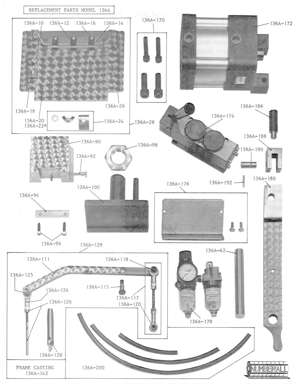
4 3. FILTER, LUBRICATOR, REGULATOR (FRL) & GAUGE (136A-178) - Located on the left hand side of the press, the FRL&G allows adjustment of the air pressure to the press, while cleaning, filtering and lubricating the air components. To adjust air pressure, release the small red plastic lock knob before adjusting the control knob. Turning the adjustment knob inward will increase air pressure up to line pressure. Turning the adjustment knob outward will decrease pressure to the press. When reducing pressure it will be necessary to cycle the press in order to get an accurate gauge reading. Tighten the locking knob after adjustment. The drain cock of the filter should be regularly checked for water. CAUTION: NEVER REMOVE SEDIMENT OR LUBRICATE BOWL BEFORE DEPRESSURIZING THE SYSTEM. The lubricator bowl should be kept supplied with non-synthetic, light oil. Oil flow can be adjusted by means of the oil flow adjustment screw on the air lubricator. A clean air supply is absolutely essential for long life of the air components. 4. TABLE ELEVATION NUT (136A-98) - This nut on the large threaded rod beneath the table, adjusts the vertical position of the table. Counter-clockwise rotation lowers the table and clockwise rotation raises the table. 5. TABLE INSERT CLAMP (136A-17) - This clamp, located on the left hand side of the table, secures the table insert. After loosening the brass screw, the insert can be moved fore and aft. Engraved markings on the left hand edge of the insert are provided for reference purposes. Each increment measures 1/16. An arrow index is stamped on the left hand guide rail. 6. TABLE LOCKING ASSEMBLY (136A-24) - The table locking assembly located beneath the table in the front center, secures the table. After loosening the wing nut, the table may be moved left or right. Tighten the wing nut after adjustment. 7. MARKING DEVICE CLAMPING SCREW (136A-92) - This brass screw located on the right hand side of the dovetail ram (136A-90), secures the marking device. The dovetail and clamping screw only serve to hold the marking device in position. The press force bears on the ram head bottom. 8. DOVETAIL RAM GIB (136A-94) - This gib located between the dovetail ram (136A-90) and the frame casting (136A-142) eliminates play in the ram head. If the ram head develops left and right play, it will be necessary to tighten the gib. While holding the two allen head setscrews (136A-96) stationary, loosen the locking nut on each. Evenly tighten the two set crews until left and right play is eliminated. Do not over-tighten. While holding the two allen head set screws stationary, retighten the locking nuts. This adjustment may be required after initial break-in.
5 Adjustments for Stamping 1. Lower the table, by rotating the elevation nut counter-clockwise, until the marking device can easily be inserted in the dovetail ram. 2. Place the material to be stamped or trial sample in the nameplate clamp or fixture. 3. KEEPING BOTH HANDS CLEAR OF THE TABLE, depress the air valve lever. Hold the lever in the down position until the arm head stops. If the marking device begins to touch the surface, lower the table further, until the ram head is in its full down position. 4. With the lever still depressed, raise the table until it touches the marking device. Release the lever. 5. Raise the table very slightly (1/16 of a turn at a time). Depress the air valve lever. Release and check the impression. If the impression is not deep enough, keep rotating the elevation nut and checking the impression until a satisfactory stamp is achieved. 6. The air pressure can be lowered to obtain a satisfactory stamping once the above is accomplished. This will protect the work piece in the event the table is raised too high. The air pressure should not exceed 80 psi. Once the above is done at 80 psi, back off the air pressure until a satisfactory stamping is produced. If the table is accidentally moved up, the press will stall at this pressure, and the part will be stamped without any damage. 7. Once adjusted the Model 136A is ready for stamping. Minor adjustments may be required due to variations in the thickness of the part. Lubrication 1. Oil holes are provided in the following places: a. On the top of the ram head (136A-90) b. On the rocker arm (136A-180), as follows: above the rocker arm shaft (136A-62) and above the piston rod yoke shaft (136A-190). Use a few drops of light oil in these places if the surface appears dry. Oil daily if the press is in continuous service. 2. The air cylinder has a permanent grease coating. If you use an FRL and add oil to the lubricator, the cylinder must be continuously lubricated from then on. As oil will wash away the grease coating. If you do add oil to the lubricator, it should be kept supplied with light non-synthetic oil. CAUTION: DO NOT
6 REMOVE THE LUBRICATOR BOWL UNTIL THE SYSTEM HAS BEEN DEPRESSURIZED. 3. On the table insert guides and the table dovetail guide, use graphite as a lubricant. Oil should not be used, as it may accumulate dirt and bind the parts. 4. Place a few drops of oil on the ram head dovetail slides if the surfaces appear dry. Oil weekly if the press is in continuous service. 5. On the table insert guides and the table dovetail guide, use the graphite as a lubricant. Oil should not be used, as it may accumulate dirt and bind the parts.
7 INSTALLATION OF OPTIONAL TRIPPING ATTACHMENT The following instructions apply to any of Numberall s bench presses: Models 131, 131A, 133, 136, 136A, and The tripping attachment is shipped assembled but will need adjustment. All mounting holes in the press have been pre-drilled. The hand clearances inside the casting are very tight and some patience is required. CAUTION: WHEN WORKING WITH THE CASTING, MAKE SURE ALL POWER SOURCES HAVE BEEN DISCONNECTED. The tripping attachment is easily installed if the press is lying on its side. 2. The linkage will attach to the press with the turnbuckle assembly (*-116) toward the rear. It is located on the right hand side of the frame casting, bolting to the rocker arm and frame casting. 3. Loosen the two jam nuts on the turnbuckle assembly. One is a left hand thread and one is a right hand thread. 4. Insert the 1/4 cap screw through the lower ball end and thread it into the 1/4 hole in the right rear inside of the frame casting. 5. Insert the shoulder screw (*-114) through the tripping arm from the right. Slide the spacer over the shoulder screw. Start the shoulder screw into the threaded hold near the back of the rocker arm. Tighten the shoulder screw. 6. Adjust the rear turnbuckle assembly by rotating the center rod until 3/4 of clearance exists between the tripping arm and the top of the dovetail ram. Tighten both turnbuckle jam nuts while holding the turnbuckle rod stationary. 7. Tighten the free motion connecting link assembly into the Model 50 Automatic Numbering Machine. Tighten the jam nut so that the ball end is aligned vertically. 8. Start the free-motion rod into the free-motion connecting link. 9. By rotating the actuating arms away from the numbering machine, it will be possible to simultaneously feed the free motion rod into the free motion linkage and slide the numbering machine into the dovetail ram. Tighten the marking device clamping screw. 10. After the press has been properly adjusted for the impression depth, cycle the press. If the numbering machine is not advancing properly, it will be necessary to screw the free motion rod either in or out of the upper ball end. Loosen the jam nut first. Adjust the rod until the numbering machine clicks into its advance position. Make sure the press makes a full cycle. If it does
8 not, then the adjustment to the tripping attachment will not be correct. Tighten the jam nut. 11. The tripping attachment is now ready for use. Do not operate a press with the tripping attachment, unless it is connected to an automatic numbering machine or the free motion rod and ball end have been removed, otherwise damage to the tripping attachment may occur. * Denotes the model number of the press for which you are installing the attachment.
9
10
11 Numberall Stamp & Tool Co., Inc. For extra copies of this manual please call or visit our website. P.O. BOX 187, 1 HIGH ST. SANGERVILLE, ME office@numberall.com TEL: FAX:
NUMBERALL STAMP & TOOL CO., INC. USER MANUAL & PARTS LIST S/N: P.O. BOX 187, 1 HIGH ST. SANGERVILLE, ME TEL: FAX:
 NUMBERALL STAMP & TOOL CO., INC. USER MANUAL & PARTS LIST MODEL 301 S/N: P.O. BOX 187, 1 HIGH ST. SANGERVILLE, ME 04479 www.numberall.com office@numberall.com TEL: 207-876-3541 FAX: 207-876-3566 MODEL
USER MANUAL & PARTS LIST MODEL 40B S/N:
 NUMBERALL STAMP & TOOL CO., INC. USER MANUAL & PARTS LIST MODEL 40B S/N: P.O. BOX 187, 1 HIGH ST. SANGERVILLE, ME 04479 www.numberall.com office@numberall.com TEL: 207-876-3541 FAX: 207-876-3566 MODEL
OPERATION, PARTS & MAINTENANCE MANUAL MODELS HB73-16 HB97-18 HB97-16 HB97-12 HB HB HB HB145-18
 OPERATION, PARTS & MAINTENANCE MANUAL MODELS HB73-16 HB97-18 HB97-16 HB97-12 HB121-18 HB121-16 HB121-14 HB145-18 Proudly Made in the USA 2 3 4 FOREWORD This manual has been prepared for the owner and operators
MODEL 36 Di-Acro Hand Shear
 OPERATOR S MANUAL & INSTRUCTIONS MODEL 36 Di-Acro Hand Shear Di-Acro, Incorporated PO Box 9700 Canton, Ohio 44711 3713 Progress Street N.E. Canton, Ohio 44705 330-455-1942 330-455-0220 (fax) Revised 01/02
Operating, Servicing, and Safety Manual Model " Foot Shear CAUTION: Read and Understand
 Operating, Servicing, and Safety Manual Model 3000 52" Foot Shear CAUTION: Read and Understand These Operating, Servicing, and Safety Instructions, Before Using This Machine. SAFETY The purpose of the
MODEL 36 and 52 FOOT SQUARING SHEARS OPERATION, PARTS & MAINTENANCE MANUAL. Proudly Made in the USA
 MODEL 36 and 52 FOOT SQUARING SHEARS OPERATION, PARTS & MAINTENANCE MANUAL Proudly Made in the USA Model 36 and 52 Foot Squaring Shear Parts View 2 Model 36 and 52 Parts List INDEX NO. 36 52 DESCRIPTION
Due to possible damage in shipping, the vertical stop assembly has been removed from this machine.
 Due to possible damage in shipping, the vertical stop assembly has been removed from this machine. To assemble, insert the threaded rod through the shroud opening in the top of the machine. Start the four
OPERATING INSTRUCTIONS 3421UX VETERANS BLVD, CARLSTADT, NJ 07072
 OPERATING INSTRUCTIONS 3421UX5-1 400 VETERANS BLVD, CARLSTADT, NJ 07072 CONTENTS DESCRIPTION... 3 OPERATOR INFORMATION... 5-8 INSTALLATION...... 4 ADJUSTMENT... 8-17 LUBRICATION... 5 INDEX Description
Hydraulic Clamp Carrier. Installation & Operation Manual
 Hydraulic Clamp Carrier Installation & Operation Manual Hydraulic Clamp Carrier Installation & Operation Manual Quick Machinery Company 8272 Peninsula Drive Kelseyville, CA 95451 phone: (707) 272-6719
TK 1014 A POWER SHEAR
 TIN KNOCKER TK 1014 A POWER SHEAR Parts Diagram & Operating Instructions TAAG INDUSTRIES CORP. 1550 SIMPSON WAY, ESCONDIDO, CA 92029 Tel: (800) 640-0746 Fax: (760) 727-9948 Website: www.tinknocker.com
25000 Series Lo-T TM Butterfly Control Valve Instructions
 November 2001 25000 Series Lo-T TM Butterfly Control Valve Instructions Instruction No. 25.1:IM PRELIMINARY STEPS Before installation, note the flow direction arrow on the valve body. The flow should enter
THE T-MAG II PRESS. Figure 6
 THE T-MAG II PRESS The Lyman T-Mag Press features a powerful compound leverage with a unique position indexable turret and quick disconnect release system. This allows you to mount several die sets, precisely
SPIDA SAW OPERATIONS MANUAL
 SPIDA SAW OPERATIONS MANUAL CM SERIAL NUMBER. OCTOBER 2000 CONTENTS Page description 1.) Contents 2.) Safety First 3.) CM Overview 4.) CM Specifications 5.) CM Installation 6.) CM Operation Setting the
Model: SCD430 SCD640. Installation & Operation Guide P/N SCD640-95
 Model: SCD430 SCD640 Installation & Operation Guide P/N SCD640-95 Model SCD430 and SCD640 Kurt has two Self-Centering vises, a four-inch jaw width (SCD430) and a six-inch jaw width (SCD640). Jaw opening
HAND SHEARS NO. 12 AND NO. 24
 OPERATOR S MANUAL & INSTRUCTIONS HAND SHEARS NO. AND NO. Di-Acro, Incorporated PO Box 9700 Canton, Ohio 7 7 Progress Street N.E. Canton, Ohio 70 0--9 0--00 (fax) Revised 0/0 Sale or distribution of manuals
Lumber Smith. Assembly Manual. If you are having problems assembling the saw and need assistance, please contact us at:
 Lumber Smith Assembly Manual If you are having problems assembling the saw and need assistance, please contact us at: 804-577-7398 info@lumbersmith.com 1 Step 1 Safety Carefully read the Owners Manual.
Crestline Dampening System. Installation Instructions. 4 ROLL DAMPENER Ryobi 3302M Itek 3985 A.B. Dick 9985 X /98
 Crestline Dampening System Installation Instructions 4 ROLL DAMPENER Ryobi 3302M Itek 3985 A.B. Dick 9985 X88-49 1/98 GENERAL INFORMATION ATTENTION CRESTLINE DAMPENER OWNER! Accel Graphic Systems provides
Hinge Boring/Insertion Machine Set Up And Operation Instructions
 Hinge Boring/Insertion Machine Set Up And Operation Instructions Manufactured In The USA By: Thompson Industries, Inc. 1018 Crosby Avenue, Sycamore, IL. 60178-0127 Ph:815-899-6670 Fax:815-899-1918 Thank
Quick Set Dovetail Jig
 Quick Set Dovetail Jig FOR HELP OR ADVISE ON THIS PRODUCT PLEASE CALL OUR CUSTOMER SERVICE HELP LINE : 01509 500359 THE MANUFACTURER RESERVES THE RIGHT TO ALTER THE DESIGN OR SPECIFICATION TO THIS PRODUCT
PEXTO NO. 137 & NO. 152 FOOT SQUARING SHEAR INSTRUCTIONS AND PARTS IDENTIFICATION
 PEXTO NO. 137 & NO. 152 FOOT SQUARING SHEAR INSTRUCTIONS AND PARTS IDENTIFICATION INSTRUCTIONS FOR ADJUSTING PEXTO FOOT SHEARS -- BEFORE OPERATING -- Remove Shears From Skids and Log in Place 1. This shear
Taper Attachment for G4016 Gear Head Lathe
 Taper Attachment for Gear Head Lathe MODEL H0775 INSTRUCTION SHEET COPYRIGHT AUGUST, 2004 BY GRIZZLY INDUSTRIAL, INC. WARNING: NO PORTION OF THIS MANUAL MAY BE REPRODUCED IN ANY SHAPE OR FORM WITHOUT THE
Assembly, Use and Care Instructions
 Assembly, Use and Care Instructions Product #336677 Instruction #1068318 Rev. F Thank you for purchasing a Caldwell Lead Sled DFT 2. The Lead Sled DFT 2 comes to you partially assembled. It will require
OPERATION, PARTS & MAINTENANCE MANUAL
 OPERATION, PARTS & MAINTENANCE MANUAL MODELS HBU48-12 and HBU72-16 6926 Smithville Hwy. McMinnville, TN 37110 Phone: 931-934-2211 Fax: 931-934-2220 Email info@tennsmith.com www.tennsmith.com Proudly Made
Crestline Dampening System. Installation Instructions. Hamada RS34 & VS34 Parent Unit DU34 Upper Unit. For Presses Originally Equipped With
 Crestline Dampening System Installation Instructions Hamada RS34 & VS34 Parent Unit DU34 Upper Unit For Presses Originally Equipped With Molleton Dampeners X88-78 01/2001 Rev-A GENERAL INFORMATION ATTENTION
1. Turn off or disconnect power to unit (machine). 2. Push IN the release bar on the quick change base plate. Locking latch will pivot downward.
. 2. Push IN the release bar on the quick change base plate. Locking latch will pivot downward.") Figure 1 Miniature Quick Change Applicators, of the end feed type, are designed to crimp end feed strip terminals to prestripped wires. Each applicator is set up to accept the strip form of certain specific
Figure 1 Miniature Quick Change Applicators, of the end feed type, are designed to crimp end feed strip terminals to prestripped wires. Each applicator is set up to accept the strip form of certain specific
No. 412, 414, 416 Operations Manual
 No. 412, 414, 416 Operations Manual CARE: Occasional oiling of moving parts with machine oil will ease operation and extend the life of the brake. Occasionally check and tighten the lower beam bracket
HA-2 INDUSTRIAL UNDERCUTTER INSTRUCTIONS. Caution!
 HA-2 INDUSTRIAL UNDERCUTTER INSTRUCTIONS Caution! The Outrigger Assembly MUST be supported and the Pawl Finger, on the Safety Pawl, engaged in the rack BEFORE loosening the two (2) Clamping Bolts. Personal
Nancy s Knit Knacks LLC 4 Yard Option Upgrade Kit Assembly Instructions and User Manual
 Nancy s Knit Knacks LLC 4 Yard Option Upgrade Kit Assembly Instructions and User Manual Thank you for purchasing our 4 Yard Option (4YO) Upgrade Kit. To install this upgrade you are simply going to assemble
#4500 BULLET SIZER & LUBRICATOR
 #4500 BULLET SIZER & LUBRICATOR Assembly Your new #4500 Bullet Sizer and Lubricator has been fully assembled at the factory, However, to facilitate packaging and shipping, the handle has been dismounted.
Fisher 667 Diaphragm Actuators Size 80 and 100
 Instruction Manual 667 Size 80 and 100 Actuators Fisher 667 Diaphragm Actuators Size 80 and 100 Contents Introduction... 1 Scope of Manual... 1 Description... 2 Specifications... 2 Maximum Pressure Limitations...
Horizontal and Vertical. Metal Cutting Band Saw MODEL: BS-115
 Horizontal and Vertical Metal Cutting Band Saw MODEL: BS-5 SAFETY. Know your band saw. Read the operator s Manual carefully. Learn the operations, applications and limitation.. Use recommended accessories.
Di-Acro 36 Power Shear
 OPERATOR S MANUAL & INSTRUCTIONS Di-Acro 36 Power Shear Di-Acro, Incorporated PO Box 9700 Canton, Ohio 44711 3713 Progress Street N.E. Canton, Ohio 44705 330-455-1942 330-455-0220 (fax) Revised 01/02 Sale
OPERATING INSTRUCTIONS MODULGRAV. Tel. +49 (0) Fax +49 (0) homepage:
 Fax +49 (0) homepage:") OPERATING INSTRUCTIONS MODULGRAV Kolpingstraße -7 D-784 Singen / Htwl. Postfach 80 D-784 Singen / Htwl. Tel. +49 (0) 77 88-0 Fax +49 (0) 77 88 66 e-mail: info@elma-ultrasonic.com homepage: www.elma-ultrasonic.com
OPERATING INSTRUCTIONS MODULGRAV Kolpingstraße -7 D-784 Singen / Htwl. Postfach 80 D-784 Singen / Htwl. Tel. +49 (0) 77 88-0 Fax +49 (0) 77 88 66 e-mail: info@elma-ultrasonic.com homepage: www.elma-ultrasonic.com
Side Winder R o u t e r L i f t.
 Woodpeckers PRECISION WOODWORKING TOOLS Side Winder R o u t e r L i f t. INSTALLATION INSTRUCTIONS The wrench handle must be pointing left in order to fully insert or remove it. Lift Wrench Once fully
Fisher 667 Diaphragm Actuator Sizes 30/30i 76/76i and 87
 Instruction Manual 667 Actuator (Size 30/30i - 76/76i and 87) Fisher 667 Diaphragm Actuator Sizes 30/30i 76/76i and 87 Contents Introduction... 1 Scope of Manual... 1 Description... 2 Specifications...
1904, 1904Pg, 1904PgSB, and 1906SB High Capacity Ratchet Knockout Drivers
 INSTRUCTION MANUAL 1904, 1904Pg, 1904PgSB, and 1906SB High Capacity Ratchet Knockout Drivers Read and understand all of the instructions and safety information in this manual before operating or servicing
Click Here to Go Back
 Click Here to Go Back Fig. -94 Fig. -97 CC42D 10. Remove the cap screw securing the gear shift stopper plate pin retainer; then remove the retainer. Fig. -95 CC45D 12. Remove the link arm and account for
CV1B Sliding Table Installation and Setup Guide
 CV1B Sliding Table Installation and Setup Guide Tech Mark, Inc 7901 Industry Drive North Little Rock, AR 72117 tel (501) 945-9393 fax (501) 945-0312 www.tech-mark.com email: info@tech-mark.com The CV1B
 GENERAL OPERATIONAL PRECAUTIONS WARNING! When using electric tools, basic safety precautions should always be followed to reduce the risk of fire, electric shock and personal injury, including the following.
SERVICE MANUAL CLINTON FEED OFF THE ARM CHAIN CUTTER WITH EXTERNAL AIR DRIVE MODEL 2115FOTA-V FOR UNION SPECIAL 35800, & YAMATO FD-62 ML2115-7A
 ML2115-7A CLINTON FEED OFF THE ARM CHAIN CUTTER WITH EXTERNAL AIR DRIVE MODEL 2115FOTA-V FOR UNION SPECIAL 35800, 36200 & YAMATO FD-62 SERVICE MANUAL 40-0164-01 ML2115-8E I. GENERAL INFORMATION A. The
Band-Master ATS Nano Pneumatic Banding Tool Operating Instructions
 Band-Master ATS 601-118 Nano Pneumatic Banding Tool CONTENTS 601-118 Overview... 3 Safety.... 5 Initial Tool Set-up... 5 Regulator assembly mounting... 5 Attach tool head to regulator.... 6 Operating instructions...
Electric Skein Winder
 Electric Skein Winder Assembly and Use Package Contents 1 - Triangular Body (w/ motor) 1 - Cross Arm 1 - Left Foot (w/ yarn guide) 1 - Right Foot 1 - Adjustable Finger (w/ yarn clip) 3 - Adjustable Fingers
FBX-PA-2AC. Third edition : April No
 FBX-PA-2AC Third edition : April 2006 No. 060058 INTRODUCTION Thank you very much for purchasing Kansai Special FBX series. Read and study this Instruction Manual carefully before you start any of the
TIN KNOCKER TK 1624 SLITTER INSTRUCTIONS & PARTS DIAGRAM. Shown with Optional Stand
 1 TIN KNOCKER TK 1624 SLITTER INSTRUCTIONS & PARTS DIAGRAM Shown with Optional Stand TAAG MACHINERY CO. (Master Distributor) 1257-B Activity Dr. Vista, CA 92081 Tel: (800) 640-0746 Fax: (760) 727-9948
.00025" PER CLICK. As you turn the adjustment screw you should be able to feel a click. Each click will change the part diameter.00025".
 ULTRA PRECISION DIAMETER ADJUSTMENT.00025" PER CLICK The ultra precision diameter adjustment is extremely accurate, as well as, quick and easy to use. The adjustment mechanism is spring loaded to take
Cyclone Upcut Cut off saw
 Cyclone Upcut Cut off saw Operation manual WARNING The operator must thoroughly read and understand this manual before operating the cut off saw or starting any servicing. All safety and warning instructions
VARIABLE SPEED WOOD LATHE
 MODEL MC1100B VARIABLE SPEED WOOD LATHE INSTRUCTION MANUAL Please read and fully understand the instructions in this manual before operation. Keep this manual safe for future reference. Version: 2015.02.02
VARIABLE SPEED WOOD LATHE. Model DB900 INSTRUCTION MANUAL
 VARIABLE SPEED WOOD LATHE Model DB900 INSTRUCTION MANUAL 1007 TABLE OF CONTENTS SECTION...PAGE Technical data.. 1 General safety rules....1-3 Specific safety rules for wood lathe.....3 Electrical information.4
Geology, Prospectors, Mining, Metallurgy, Assaying, Environmental, Geotechnical
 LEGEND INC. Geology, Prospectors, Mining, Metallurgy, Assaying, Environmental, Geotechnical 988 Packer Way Sparks, NV 89431 Tel: (786) 786-3003 Fax: (775) 786-3613 Email: info@lmine.com Web: www.lmine.com
Crestline Dampening System. Installation Instructions. Ryobi 2700, 2800, 3200, 3200E Itek 950, 960, 975 Parent. X /98 Rev-A
 Crestline Dampening System Installation Instructions Ryobi 2700, 2800, 3200, 3200E Itek 950, 960, 975 Parent X88-30 3/98 Rev-A GENERAL INFORMATION ATTENTION CRESTLINE DAMPENER OWNER! Accel Graphic Systems
FBX1104P FBX1104 FBX1106P FBX1106
 FBX1104P FBX1104 FBX1106P FBX1106 Second edition : September 2004 No. 040037 INTRODUCTION Thank you for your purchasing Kansai Special's FBX Series. Read and study this instruction manual carefully before
Greenslade & Company Rockwell Hardness Tester, Dial Type
 Greenslade & Company Rockwell Hardness Tester, Dial Type Greenslade Hardness Tester Operating Instructions & Parts Manual Please read and save these instructions. Read carefully before attempting to assemble,
THIS KIT INCLUDES: 8 M8-1.25X40MM BOLTS WITH WASHERS 8 M8-1.25X30MM BOLTS WITH WASHERS RIGHT AND LEFT HINGE
 Sal es@lambodoorscanada. com 2407A Kal adarave,ottawa,on K1V 8B9 THIS KIT INCLUDES: 8 M8-1.25X40MM BOLTS WITH WASHERS 8 M8-1.25X30MM BOLTS WITH WASHERS RIGHT AND LEFT HINGE 2 SHOCKS 565 PSI 2 SHOULDER
UNPACKING. Thank you for purchasing the Manual Capsule Filling Machine from KARISHMA PHARMA MACHINES.
 UNPACKING Thank you for purchasing the Manual Capsule Filling Machine from KARISHMA PHARMA MACHINES. Please take sufficient time and read this manual carefully before you start installation and operation
CORVETTE CORVETTE REV: Made in USA U.S. PATENT #6,808,223; #6,845,547; #7,140,075; #7,059,655 and other patents pending.
 CORVETTE 2005-2006 CORVETTE 2005-2007 REV: 7-2-07 Made in USA U.S. PATENT #6,808,223; #6,845,547; #7,140,075; #7,059,655 and other patents pending. Page 1 of 12 CORVETTE C6 2005-2007 THIS KIT INCLUDES:
OPERATION, PARTS & MAINTENANCE MANUAL
 Model HB121-16 Shown MODELS HB73-16 HB97-18 HB97-16 HB97-12 HB121-18 HB121-16 HB121-14 HB145-18 OPERATION, PARTS & MAINTENANCE MANUAL Model: Serial #: Purchased From: Date Received: 6926 Smithville Hwy.,
General Wood Shop Notes
 General Wood Shop Notes Restricted Materials No METAL or BONE of any kind on any machine or in the room o See additional restrictions individual machine All reclaimed and other than new lumber must be
Table of Content. Machine Features and Functions. Specifications. Configuration and Working Principle 5. Machine Operation. Machine Adjustments
 Table of Content Safety Instructions Machine Features and Functions Specifications 2 3 4 Configuration and Working Principle 5 Machine Operation 7 Machine Adjustments 8 Machine Installation 9 Machine Remove
SERIES I MILLING MACHINES
 INSTALLATION, OPERATION, MAINTENANCE, AND PARTS LIST SERIES I MILLING MACHINES TP5260 Revised: August 29, 2005 Manual No. M-450 Litho in U.S.A. Part No. M -0009500-0450 June, 2003 MAINTENANCE PROCEDURES
TK 422 PORTABLE BRAKE
 1 TIN KNOCKER TK 422 PORTABLE BRAKE INSTRUCTIONS & PARTS DIAGRAM TAAG MACHINERY CO. (Master Distributor) 1257-B Activity Dr. Vista, Ca 92081 Tel: (800) 640-0746 Fax: (760) 727-9948 Website: www.tinknocker.com
INSTRUCTIONS FOR 1431 Door Closer with Hold Open Arms 1431 SERIES ADJUSTABLE FROM SIZE 1 THRU 6
 INSTRUCTIONS FOR Door Closer with Hold Open Arms SERIES ADJUSTABLE FROM SIZE THRU 6 FOR INSTALLATION ASSISTANCE CALL SARGENT AT -800-77-77 / www.sargentlock.com Installation Instructions based on Application
Crestline Dampening System. Installation Instructions. Shinohara 66. X /98 Rev-A 2598
 Crestline Dampening System Installation Instructions Shinohara 66 X88-58 8/98 Rev-A 2598 GENERAL INFORMATION ATTENTION CRESTLINE DAMPENER OWNER! Accel Graphic Systems provides parts and service through
 Operating Instructions Table of Contents Page Operating Instructions 2-3 Changing Character Dial Instructions 4 3/16 Line and Letter Charts 5 Assembly Drawings 6-7 Repair Parts List 8 Trouble Shooting
Thomas Scientific Swedesboro, NJ U.S.A.
 Thomas Scientific Swedesboro, NJ 08085-0099 U.S.A. Wiley Mini Mill 3383-L10 (115 V, 60 HZ) USE AND CARE OF CATALOG NUMBER: 3383-L10 Wiley Mini Mill (115 V, 60 HZ) PRELIMINARY 1. Mill has been properly
8" BENCH SHEAR INSTRUCTIONS. Item #20198
 8" BENCH SHEAR INSTRUCTIONS Item #20198 Your EASTWOOD 8 BENCH SHEAR for metal cutting is designed for quickly and cleanly cutting mild steel, aluminum and other metals. Torque-amplifying, compound linkage
H2-50 Hydrogen Generator Field Update
 This field update is intended to provide extra protection in the event the H2 generation cell fractures or cracks. Please add the additional parts to your H2-50 as soon as possible. Please take a digital
BHJ Products, Inc. Parts List & Instructions
 Product Name: Lifter-Tru Kit for Ford Windsor & SVO Small Block V8 Page 1 of 5 Kit Contents: 2x End Plates 2x 5/8 Threaded Adjustment Sleeves 1x Front Angle Bracket 2x 5/8 Adjustment Sleeve Spacers * 1x
Fig. 2 DORMA-Glas Stand/Issue 02/03 Seite/Page 1/7
 FSW Installation instructions Track rail 75 x 72 mm 1. Ceiling substructure and installation of the track rail (Fig. 1): The track rail must be bolted over its entire length (including the stacking track
30AUTO Speed Lathe Manual
 30AUTO Speed Lathe Manual Standard Features 3/4 HP Motor Air-Collet Closure 1800 RPM, Single Speed Electric Brake Cast Housing 5C Collets 3 Phase / 240 Volts DESCRIPTION: The Crozier Model 30AUTO Automotive
The DeltaGrip System. Safety and Operating Instructions. Trigger. Air Supply Connection. Handle Assembly. Air Line Assembly.
 The DeltaGrip System Safety and Operating Instructions Trigger Air Supply Connection Handle Assembly Air Line Assembly Punch Die Pneumatic Diaphragm Assembly Shackle, Pin & Jam Nut Jaw Frame Shoulder Screw
B-Too Drilling and Tapping Machine Instruction and Maintenance Manual
 B-Too Drilling and Tapping Machine Instruction and Maintenance Manual Thank you for your purchase of the B-Too Drilling and Tapping Machine. Please read and understand this short operation manual. Our
Lockformer / 16 Gauge Speednotch
 Lockformer / 16 Gauge Speednotch INSTALLATION PRELIMINARY: After uncrating, locate unit, with or without base skid, to area of operation. Unbind foot switch cord and cylinder hoses and remove gauge pin
MSR/MSB Mechanical Setting Tool
 Tech Unit No: 0620000004 Revision: B Approved By: Quality Engineer Date: 2014-12-16 MSR/MSB Mechanical Setting Tool FEATURES: Special designed Bow Spring provides positive control and allows one size Mechanical
Operating, Servicing, and Safety Manual Model # & 72 Ultimate Box & Pan Brake
 Operating, Servicing, and Safety Manual Model # 2800 48 & 72 Ultimate Box & Pan Brake CAUTION: Read and Understand These Operating, Servicing, and Safety Instructions, Before Using This Machine. 1-800-467-2464
PAN AND BOX BRAKE INSTRUCTIONS. Item #20649
 PAN AND BOX BRAKE INSTRUCTIONS Item #20649 The EASTWOOD 12 & 24 PAN AND BOX BRAKES are precision engineered metal working tools designed to produce accurate, variable length bends in angles up to 135 in
OPERATING INSTRUCTIONS FOR MODEL SPR-25 Manual Stencil Printer
 OPERATING INSTRUCTIONS FOR MODEL SPR-25 Manual Stencil Printer TABLE OF CONTENTS I. INSTALLATION...3 II. SET-UP...4 III. Z AXIS ADJUSTMENT (Screen Height)...6 IV. X, Y AND Ø ADJUSTMENTS...6 V. SQUEEGEE
4" METAL BENDER INSTRUCTIONS. Part #20521
 4" METAL BENDER INSTRUCTIONS Part #20521 The EASTWOOD 4 METAL BENDER is a high quality, industrial style tool capable of generating a powerful 2-1/2 tons of pressing force to create 90 or lesser repeatable
Additional Information
 NUMBER: 1 34 13 S.M. REF.: Listed in Table ENGINE: EPA04/07 Series 60 DATE: January 2013 SUBJECT: CHECKING CYLINDER LINER PROTRUSION ADDITIONS, REVISIONS, OR UPDATES Publication Number Platform Section
OWNERS MANUAL FOR MEC 306XP/408XP WOBBLE
 OWNERS MANUAL FOR MEC 306XP/408XP WOBBLE PLEASE READ AND FULLY UNDERSTAND THE INSTRUCTIONS PRIOR TO SETTING OR TUNING THE MACHINE. Page 1 CAUTION: ANY MEC CLAY TARGET MACHINE MUST BE IN THE DISARMED STATE
LPK1550 Hydraulic Crimping Tool 15-ton
 SERVICE MANUAL LPK1550 Hydraulic Crimping Tool 15-ton Serial Code FYF Read and understand all of the instructions and safety information in this manual before operating or servicing this tool. Register
Operating, Servicing, and Safety Manual Model # 100 Standard Hydraulic Tubing Notcher Model #100-U Heavy Duty Hydraulic Tubing Notcher
 Operating, Servicing, and Safety Manual Model # 100 Standard Hydraulic Tubing Notcher Model #100-U Heavy Duty Hydraulic Tubing Notcher Model # 100 Standard Model #100-U Heavy Duty CAUTION: Read and Understand
Warnings. Description. Prior to Installation Tools Needed
 Warnings Failure to act in accordance with the following may result in death or personal injury. The JT Strong Arm Stabilizer System is intended to eliminate chassis movement in travel trailers and fifth
OWNER S MANUAL. Safety. Please read this owner s manual before use and keep it at hand for reference. Warranty
 Please read this owner s manual before use and keep it at hand for reference. OWNER S MANUAL Safety Important safety instructions for using the INCRA Miter5000 Before using the INCRA Miter5000, read and
M4 Foot Operated Underpinner Instruction Manual
 M4 Foot Operated Underpinner Instruction Manual M4 Walker Rd, Bardon Hill, Coalville, Leicestershire LE67 1TU, England Tel. +44 (0)130 1692, Fax +44 (0)130 16929 e mail sales@framerscorner.co.uk M4 Underpinner
DELUXE AIR PRESSURE CASTING MACHINE MODEL # S
 DELUXE AIR PRESSURE CASTING MACHINE MODEL # S INSTALLATION 99-002-D4AP 99-002-D4AP-A MAINTENANCE The points to look for in order to obtain a long and trouble free operation are: a. See that the oil fog
Astro-Physics Inc. 400QMD Lubrication/Maintenance Guide
 Astro-Physics Inc. 400QMD Lubrication/Maintenance Guide The following guidelines should be followed to lubricate the three main parts of the 400QMD mount. The QMD stands for Quartz Micro-Drive controller.
Setup & Operating INSTRUCTIONS. for (FOR PIN FITTING AND ROD RECONDITIONING)
") I-AG-400A Setup & Operating INSTRUCTIONS for SUNNEN AG-400 PRECISION GAGE (FOR PIN FITTING AND ROD RECONDITIONING) AG-400 Precision Bore Gage Range:.375 to 2.687 in. (9,5-68mm) Graduation of Dial:.0001
I-AG-400A Setup & Operating INSTRUCTIONS for SUNNEN AG-400 PRECISION GAGE (FOR PIN FITTING AND ROD RECONDITIONING) AG-400 Precision Bore Gage Range:.375 to 2.687 in. (9,5-68mm) Graduation of Dial:.0001
TOOLS AND INSTALLATION
 TOOLS AND INSTALLATION Safe, leak-free operation of any high-pressure system is dependent on correctly prepared and installed connections. This section outlines proper instructions for the machining and
4.4 PUMP MAINTENANCE MODELS: DB, DC, DF, DG, DJ, DL
 4.4 PUMP MAINTENANCE MODELS: DB, DC, DF, DG, DJ, DL 4.4.1 EXPLODED VIEW DRAWING REF. QTY. DB DC DF DG DJ DL DESCRIPTION PART # 1 1 ADAPTOR FRAME 034007 2 12 LOCK WASHER 3/8 x 1/8 S.S. 034004 3 12 HEX HEAD
MSR/MSB Mechanical Setting Tool
 Tech Unit No: 0620000004 Revision: C Approved By: Quality Engineer Date: 201-1-9 MSR/MSB Mechanical Setting Tool FEATURES: Special designed Bow Spring provides positive control and allows one size Mechanical
Clayton Off Road COR COR COR
 Clayton Off Road COR-4806011 COR-4806021 COR-4806031 JEEP GRAND CHEROKEE WJ LONG ARM UPGRADE KITS (1999-2004 WJ) NOTES: This product requires general welding, fabrication and automotive mechanic skills.
MODEL W1.0X305A(12 ) MODEL W1.0X610A(24 ) HAND BENDING BRAKE ASSEMBLY&OPERATING INSTRUCTION
 MODEL W1.0X610A(24 ) HAND BENDING BRAKE ASSEMBLY&OPERATING INSTRUCTION") MODEL W1.0X305A(12 ) MODEL W1.0X610A(24 ) HAND BENDING BRAKE ASSEMBLY&OPERATING INSTRUCTION 1 SAVE THIS MANUAL You will need the manual for the safety warning and precautions, assembly instructions, operating
MODEL W1.0X305A(12 ) MODEL W1.0X610A(24 ) HAND BENDING BRAKE ASSEMBLY&OPERATING INSTRUCTION 1 SAVE THIS MANUAL You will need the manual for the safety warning and precautions, assembly instructions, operating
Removing Right-Side. Components. Right-Side. Components. Click Here to Go Back AT THIS POINT
 Click Here to Go Back NOTE: There is an oil passage beneath the driven gear/drive gear assembly. This passage should be plugged prior to removing the driven gear and drive gear. Failure to do so could
400A 40113V, 401A 40120V, & 401AL 40120VL ALUMINUM VERTICAL 4000 LB LIFT INCLUDES SCREW LEG ASSEMBLY INSTRUCTIONS
 12/11/07 PAGE 1 OF 12 400A 40113V, 401A 40120V, & 401AL 40120VL ALUMINUM VERTICAL 4000 LB LIFT INCLUDES SCREW LEG ASSEMBLY INSTRUCTIONS Thank you for purchasing our product! *Please read these instructions
EllisSaw.com. EllisSaw.com P.O. Box Verona, WI
 P.O. Box 9019 Verona, WI 9-019 GENERAL OPERATING & SAFETY INSTRUCTIONS * READ INSTRUCTIONS BEFORE USE * CAUTION: Disconnect power supply cord from power source when doing repair work or changing belt.
MODEL T TON HYDRAULIC PRESS INSTRUCTIONS (For Machines Mfd. Since 10/17)
") MODEL T1241 20-TON HYDRAULIC PRESS INSTRUCTIONS (For Machines Mfd. Since 10/17) For questions or help with this product contact Tech Support at (570) 546-9663 or techsupport@grizzly.com Identification
MODEL T1241 20-TON HYDRAULIC PRESS INSTRUCTIONS (For Machines Mfd. Since 10/17) For questions or help with this product contact Tech Support at (570) 546-9663 or techsupport@grizzly.com Identification
N. 15th Street, Middlesboro, KY FLIP TARP DUMP BODY INSTALLATION INSTRUCTIONS
 1-800-248-7717 1002 N. 15th Street, Middlesboro, KY 40965 FLIP TARP DUMP BODY INSTALLATION INSTRUCTIONS Congratulations on your purchase of a Mountain Flip Tarp Dump Body tarping system. With tarping systems
ISH-R150 MANUAL ROCKWELL HARDNESS TESTER OPERATION MANUAL
 MN-ISH-R15-E www.insize.com ISH-R15 MANUAL ROCKWELL HARDNESS TESTER OPERATION MANUAL Attention Description This Instruction Manual shall be carefully read through in prior to use of the apparatus to clearly
OWNER'S MANUAL Issue 2 - December 14, 2000
 OWNER'S MANUAL AL Issue 2 - December 14, 2000 Copyright 2000 GAMMA Sports - All Rights Reserved Provided by www.gssalliance.com OWNER'S MANUAL TABLE OF CONTENTS PAGE 1... WARRANTY PAGE 2...FEATURES PAGE
LU6X-130 Instructions and Parts List (including LU6X Basic) Operating Instructions
 Operating Instructions") LORTONE LU6X-130 Item # 061-092 LU6X Basic Item # 061-090 LU6X-130 Instructions and Parts List (including LU6X Basic) Operating Instructions Introduction The LU6X is one the most versatile pieces of equipment
LORTONE LU6X-130 Item # 061-092 LU6X Basic Item # 061-090 LU6X-130 Instructions and Parts List (including LU6X Basic) Operating Instructions Introduction The LU6X is one the most versatile pieces of equipment