USER MANUAL & PARTS LIST MODEL 40B S/N:
|
|
|
- Dwayne Atkinson
- 6 years ago
- Views:
Transcription

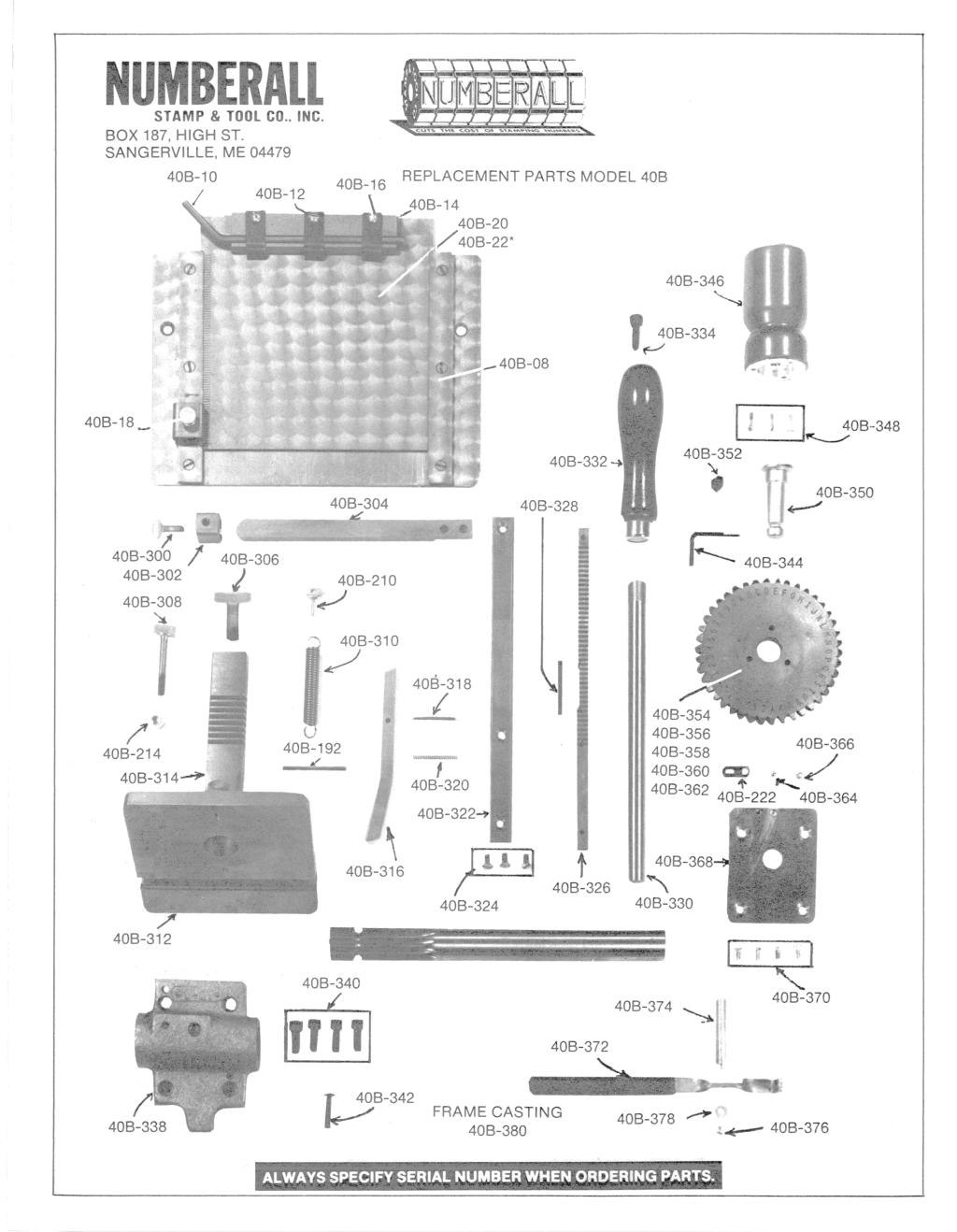
1 NUMBERALL STAMP & TOOL CO., INC. USER MANUAL & PARTS LIST MODEL 40B S/N: P.O. BOX 187, 1 HIGH ST. SANGERVILLE, ME office@numberall.com TEL: FAX:
2 MODEL 40B NUMBERING & LETTERING PRESS Uncrating Procedure 1. Remove the cardboard liner contained in the shipping container. 2. The Model 40B may now be removed directly upward. The press weighs 40 pounds and should be lifted with caution. 3. Remove the wooden shipping base attached to the press. This base will restrict handle travel. 4. Bolt the press securely to a solid bench to avoid accidental upset. Make sure to allow for full handle travel. 5. Any shipping damage to the press must be reported immediately to the common carrier and to Numberall. Product Description The Model 40B is a manually operated press, designed for stamping name tags, keys and other small parts. Equipped with the standard table, the Model 40B will stamp over an area 4 x 5. It will stamp 4-1/4 from the top edge of a tag and will accept material up to 5-3/4 wide. Extra long tables and spacing racks are available. The Model 40B stamps one character at a time and advances automatically after each impression to assure correct spacing and alignment. Depth of impression is easily adjustable and repeatable. Strip Holders and Nests are available to hold any shaped part. A standard clamping mechanism accepts parts up to 1/8 thick. Function of Controls 1. DIAL SELECTOR KNOB (40B-386) - The dial selector knob positions the characters to be stamped. A pointer, fastened on top of the casting above the dial, points to the character selected. 2. ADJUSTABLE TENSION BLOCK ASSEMBLY - (40B-363) Located behind the character dial is the adjustable tension block assembly. By turning the brass screw, the tension on the dial can be adjusted. Too light a tension may Revision # 2.0
3 not allow the dial to seat properly. Too tight of a tension will make the dial difficult to move. 3. OPERATING HANDLE (40B-332) - The operating handle, located on the right side of the press, when depressed, moves the table up and down. CAUTION: When experimenting with the handle, be careful not to accidentally stamp the table. KEEP HANDS CLEAR OF TABLE. Each time the handle is depressed, a character is stamped and the table moves one space to the left. Moving the handle a half-stroke and back up, will advance the table without stamping a character. It is important to make sure the handle is returned to its full up-right position, otherwise the table will not space properly. 4. TABLE RELEASE LEVER (40B-372) - The table release lever is located on the right-hand side, underneath the table. By depressing this handle, the table can be manually moved to the right margin stop. 5. DEPTH OF IMPRESSION SCREW (40B-306) - The depth of impression adjustment screw is a silver knurled screw located in the front, near the bottom of the press. This screw limits the upward travel of the table. Turning the screw outward (down), will allow the table to move further upward. 6. SPACING ADJUSTMENT SCREW (40B-308) - This screw is a silver, knurled screw located on in the front of the press, directly below the table. The screw has a jam nut, which must be loosened for adjustment. This screw limits the downward travel of the table. Turning the screw inward (upward) will allow the table to move further downward. By adjusting the downward limit of the table travel, letter spacing can be controlled. Before adjustment, the machine may single space, fail to space, or multiple space. For each different character size or if material thickness changes, an adjustment may need to be made. During adjustment, make sure the handle is returned to the full, upright position. 7. TABLE STOP CLAMP (40B-302) - The table stop clamp is located on the right-hand side, on the table stop bar (40B-304). The stop limits the right-hand travel of the table, which controls the left margin. 8. TABLE INSERT CLAMP ASSEMBLY (40B-17) - This clamp, located on the left-hand side of the table, secures the table insert. After loosening the brass screw, the insert can be moved forwards and backwards. Engraved markings on the left-hand edge of the insert are provided for reference purposes. Each increment measures 1/16. An arrow index is stamped on the left-hand side. Adjustments for Stamping 1. Place the material to be stamped on the table and secure it with the table clamps or special holding fixture (a special nest or slide). If a piece of scrap Revision # 2.0
4 material is to be used for setup, make sure it is the same thickness of the actual material to be stamped. 2. Center the table. This is accomplished by depressing moving the operating table left or right. Loosen the table insert clamp and move the table fore or aft. Return the handle to the full, upright position after moving the table. 3. Turn the depth of impression screw all the way inward. 4. Depress the operating the operating handle fully and make sure the character dial does not touch the material that is to be stamped. 5. While holding the operating handle in the down position, turn the depth of impression screw outward until the character dial touches the work piece. Turn the screw outward 1/4th of a turn and try a sample stamping. Make sure the handle is fully depressed against the depth of impression screw. The screw may have to be adjusted until a suitable depth is obtained. 6. If the operating handle is in an uncomfortable position, it can be adjusted as follows: a. Remove the black button head screw, which keeps the table elevation gear from moving left or right. It is located about 1 to the left of the spacing adjustment screw on the front of the press. b. Slide the operating handle to the right and reposition it once it clears the press. Make sure the handle can make a full cycle. c. Tighten the button head screw. 7. To set the table stop, first loosen the thumb screw on top of the stop and slide the stop to the right hand end of the stop bar. Depress the table release lever and slide the table until the character wheel is about one space to the left of the proper location. Release the table release lever. Operate the press handle for one complete cycle. Slide the stop against the right-hand side of the table and tighten the thumb screw. 8. The table insert can be moved fore and aft for line spacing. Loosen the table insert clamp on the left-hand side of the table. Line to line spacing can be aligned by using the stamped marks on the side of the table insert, and the arrow on the guide rail. Each line measures 1/16 spacing. Retighten the clamp after each adjustment. Character Dial and Spacing Rack Removal & Installation 1. Remove the allen set screw, located just behind the character dial on the right-hand side of the casting. Remove the character dial from the press. Revision # 2.0
5 2. Remove the three screws that hold the dial to the dial knob and remove the dial. 3. Replace the dial and assemble the dial to the dial knob. 4. Re-tighten the set screw until the character dial is pulled snugly to the dial plate. DO NOT OVER-TIGHTEN. The character dial should turn easily, but should not have fore and aft play. 5. Depress the table release lever and pull the table completely off the press to the left. The spacing rack is located on the underside of the table. 6. Remove the three screws that hold the spacing rack, which are located on the underside of the table. 7. Exchange the rack, replace the dovetail strip and very slightly tighten the three screws. Now re-insert the table. It will be necessary to depress the table release lever in order not to damage the spacing pawl. Once the table is on the press, tighten the right hand screw securely. Then tighten the left hand screw and the middle screw last. Lubrication & Maintenance 1. An oil hole is provided on the front of the press just below the spacing adjustment screw. A few drops of light oil should be applied here if bearing surfaces appear dry. Lubricate once a day if used continuously. 2. Lubricate the rear character dial surface, the table insert guides and the table dovetail strip with dry lubricant. DO NOT USE OIL. Revision # 2.0
6
7
8 Numberall Stamp & Tool Co., Inc. For extra copies of this manual please call or visit our website. P.O. BOX 187, 1 HIGH ST. SANGERVILLE, ME office@numberall.com TEL: FAX:
USER MANUAL & PARTS LIST MODEL 136A S/N:
 NUMBERALL STAMP & TOOL CO., INC. USER MANUAL & PARTS LIST MODEL 136A S/N: P.O. BOX 187, 1 HIGH ST. SANGERVILLE, ME 04479 www.numberall.com office@numberall.com TEL: 207-876-3541 FAX: 207-876-3566 MODEL
NUMBERALL STAMP & TOOL CO., INC. USER MANUAL & PARTS LIST S/N: P.O. BOX 187, 1 HIGH ST. SANGERVILLE, ME TEL: FAX:
 NUMBERALL STAMP & TOOL CO., INC. USER MANUAL & PARTS LIST MODEL 301 S/N: P.O. BOX 187, 1 HIGH ST. SANGERVILLE, ME 04479 www.numberall.com office@numberall.com TEL: 207-876-3541 FAX: 207-876-3566 MODEL
 Operating Instructions Table of Contents Page Operating Instructions 2-3 Changing Character Dial Instructions 4 3/16 Line and Letter Charts 5 Assembly Drawings 6-7 Repair Parts List 8 Trouble Shooting
JUMBO STENCIL CUTTING MACHINE PARTS LIST AND OPERATING MANUAL
 JUMBO STENCIL CUTTING MACHINE PARTS LIST AND OPERATING MANUAL Marion, IL USA STK. NO. 5800-152, REV A Warning: This machine contains pinch points which can injure personnel when not used properly. This
Due to possible damage in shipping, the vertical stop assembly has been removed from this machine.
 Due to possible damage in shipping, the vertical stop assembly has been removed from this machine. To assemble, insert the threaded rod through the shroud opening in the top of the machine. Start the four
Replacing the Reciprocator on an SWF Multi-head.
 Replacing the Reciprocator on an SWF Multi-head. Follow the instructions below to replace the reciprocator in the SWF multi-head machines. The tools required are found in the tool kit that came with the
Operating, Servicing, and Safety Manual Model " Foot Shear CAUTION: Read and Understand
 Operating, Servicing, and Safety Manual Model 3000 52" Foot Shear CAUTION: Read and Understand These Operating, Servicing, and Safety Instructions, Before Using This Machine. SAFETY The purpose of the
WOLF PUP LOOM TM & WOLF PUP LT LOOM TM
 WOLF PUP LOOM TM & WOLF PUP LT LOOM TM Assembly Instructions FL3000 FL3006 FL3009 WOLF PUP WOLF PUP LT Find out more at schachtspindle.com Schacht Spindle Company 6101 Ben Place Boulder, CO 80301 p. 303.442.3212
MODEL 36 Di-Acro Hand Shear
 OPERATOR S MANUAL & INSTRUCTIONS MODEL 36 Di-Acro Hand Shear Di-Acro, Incorporated PO Box 9700 Canton, Ohio 44711 3713 Progress Street N.E. Canton, Ohio 44705 330-455-1942 330-455-0220 (fax) Revised 01/02
Assembly, Use and Care Instructions
 Assembly, Use and Care Instructions Product #336677 Instruction #1068318 Rev. F Thank you for purchasing a Caldwell Lead Sled DFT 2. The Lead Sled DFT 2 comes to you partially assembled. It will require
OPERATING INSTRUCTIONS 3421UX VETERANS BLVD, CARLSTADT, NJ 07072
 OPERATING INSTRUCTIONS 3421UX5-1 400 VETERANS BLVD, CARLSTADT, NJ 07072 CONTENTS DESCRIPTION... 3 OPERATOR INFORMATION... 5-8 INSTALLATION...... 4 ADJUSTMENT... 8-17 LUBRICATION... 5 INDEX Description
OPERATING INSTRUCTIONS MODULGRAV. Tel. +49 (0) Fax +49 (0) homepage:
 Fax +49 (0) homepage:") OPERATING INSTRUCTIONS MODULGRAV Kolpingstraße -7 D-784 Singen / Htwl. Postfach 80 D-784 Singen / Htwl. Tel. +49 (0) 77 88-0 Fax +49 (0) 77 88 66 e-mail: info@elma-ultrasonic.com homepage: www.elma-ultrasonic.com
OPERATING INSTRUCTIONS MODULGRAV Kolpingstraße -7 D-784 Singen / Htwl. Postfach 80 D-784 Singen / Htwl. Tel. +49 (0) 77 88-0 Fax +49 (0) 77 88 66 e-mail: info@elma-ultrasonic.com homepage: www.elma-ultrasonic.com
M4 Foot Operated Underpinner Instruction Manual
 M4 Foot Operated Underpinner Instruction Manual M4 Walker Rd, Bardon Hill, Coalville, Leicestershire LE67 1TU, England Tel. +44 (0)130 1692, Fax +44 (0)130 16929 e mail sales@framerscorner.co.uk M4 Underpinner
Basic steps to time the Gammill quilting machine s rotary sewing hook
 Basic steps to time the Gammill quilting machine s rotary sewing hook 1.) Turn the machine off and unplug it. 2.) With the needle bar in the raised position, remove the bobbin and bobbin case. 3.) Remove
CV1B Sliding Table Installation and Setup Guide
 CV1B Sliding Table Installation and Setup Guide Tech Mark, Inc 7901 Industry Drive North Little Rock, AR 72117 tel (501) 945-9393 fax (501) 945-0312 www.tech-mark.com email: info@tech-mark.com The CV1B
Range height adjustable assembly
 Table of contents Digital handset operation 3 Height adjustable bench kit 4-5 Cable carrier 6 Ganging tray and ganging rail 7 Height adjustable return frame kit 8 Cable entry pole 9 24 and 30 d worksurfaces
Model: SCD430 SCD640. Installation & Operation Guide P/N SCD640-95
 Model: SCD430 SCD640 Installation & Operation Guide P/N SCD640-95 Model SCD430 and SCD640 Kurt has two Self-Centering vises, a four-inch jaw width (SCD430) and a six-inch jaw width (SCD640). Jaw opening
CONTENTS PRECAUTIONS BEFORE STARTING OPERATION PREPARATION FOR OPERATION CAUTIONS ON USE OPERATION
 CONTENTS PRECAUTIONS BEFORE STARTING OPERATION ------------------------------------- 1 PREPARATION FOR OPERATION 1. Adjustment of needle bar stop position ---------------------------------------------------------
Replacing the Reciprocator on the SWF Compact Series Machine (601C and 1201C)
") Follow the instructions below to replace the reciprocator in the SWF Compact series machines. The tools required can be found in the tool kit that came with the machine. Preparation 1. First, place the
Follow the instructions below to replace the reciprocator in the SWF Compact series machines. The tools required can be found in the tool kit that came with the machine. Preparation 1. First, place the
FOLDING TONNEAU RACK. 1. Rack Rail Assembly
 FOLDING TONNEAU RACK Package Contents (2) Load Bars (4) Load Bar End Caps (4) ¼-20 x 9/16 Narrow Shoulder Hex Head Screw (28) ¼ Flat Washers (24) ¼ Split Lock Washers (20) ¼-20 x ¾ long Button Head Screws
Hydraulic Clamp Carrier. Installation & Operation Manual
 Hydraulic Clamp Carrier Installation & Operation Manual Hydraulic Clamp Carrier Installation & Operation Manual Quick Machinery Company 8272 Peninsula Drive Kelseyville, CA 95451 phone: (707) 272-6719
CMT Enlock Jig Owner s Manual
 Thank you for purchasing the CMT Enlock Jig. This jig will simplify joinery in your shop, and on the job site. Please read the instructions thoroughly before using the Enlock Jig. Router requirements A
Introduction to Carpentry Power Tools
 Youth Explore Trades Skills Introduction to Carpentry Power Tools Description s use power tools every day, and the ability to use these tools correctly and safely is paramount. In this Activity Plan, students
UK10 UK11. First published: June No.KX03023
 UK10 UK11 First published: June 2003 No.KX03023 INTRODUCTION Thank you for purchasing Kansai Special s UK series machine. Please study this instruction manual carefully before operating the machine. 1.
RANGE DIGITAL HANDSET OPERATION. 1. Panel. 2. Initialization Procedure. 3. Move Up & Down. 4. Set Memory Positions. 5. Move to the Memorized Positions
 INSTRUCTION SHEET #2577INS PART #1730534 DIGITAL HANDSET OPERATION OPERATION INSTRUCTIONS 1. Panel 1 Button: Preset 1 2 Button: Preset 2 3 Button: Preset 3 S Button: Select Display: Reads in 1 / 2 " Increments
LX1 Maintenance Manual for Model LX1B. Table of Contents 1. GENERAL DISASSEMBLY, ASSEMBLY AND ADJUSTMENT COMPONENTS...
 KTI KITO Technical Information LX1 Maintenance Manual for Model LX1B LX1-1.1.2 1 / 14 Edition: D 03.06 Table of Contents 1. GENERAL...2 2. DISASSEMBLY, ASSEMBLY AND ADJUSTMENT...2 3. COMPONENTS...3 4.
TOYOTA TUNDRA CARGO DIVIDER Preparation. Part Number: PT
 Preparation Part Number: PT767-34070 Kit Contents 1 1 Divider Screen 2 1 LH Bracket with Warning Label 3 1 RH Bracket without Warning Label NOTE: Part number of this accessory may not be the same as the
STENCIL MACHINE OPERATION uline.com H-259, H-347 H-408 CUTTING THE OIL BOARD INSERTING THE OIL BOARD
 H-259, H-347 H-408 π STENCIL MACHINE 1-800-295-5510 uline.com OPERATION NOTE: No assembly is necessary after you unpack your machine. INSERTING THE OIL BOARD 1. Move the release lever to the right. This
BHJ Products, Inc. Parts List & Instructions
 Product Name: Lifter-Tru Kit for Ford Windsor & SVO Small Block V8 Page 1 of 5 Kit Contents: 2x End Plates 2x 5/8 Threaded Adjustment Sleeves 1x Front Angle Bracket 2x 5/8 Adjustment Sleeve Spacers * 1x
Dream Fabric Frame Assembly Instructions
 Dream Fabric Frame Assembly Instructions Copyright January 1, 2016 Jim M. Bagley, GraceWood, Inc (Reproduction Prohibited) Version 2.4 Table Of Contents Parts List 3 Step 1: Table Set Up 6 Step 2: Install
Operating Instructions
 Operating Instructions Holding the material against the angle gauge slide it into the forming head. Be sure that the material remains against the gauge until work is finished. NOTE: This machine will handle
Model 20: Home & Garden Cart
 Model 20: Home & Garden Cart Parts List Step 1: A: Install two ¾ Bolts (C) through the rear trim piece on the Bottom Panel (S) and attach to Lock Nuts. (Lock nuts on bottom side) B: Place left Side Panel
BHJ Products, Inc. Parts List & Instructions
 Product Name: O-Ring Groove Cutter Page 1 of 6 Kit Contents: 1x Cutter Head Assembly with Handle & Adjustable Tool Block 1x Graduated Adjusting Screw 1x Adjustable Tool Holder 1x Carbide Insert (Size of
No. 412, 414, 416 Operations Manual
 No. 412, 414, 416 Operations Manual CARE: Occasional oiling of moving parts with machine oil will ease operation and extend the life of the brake. Occasionally check and tighten the lower beam bracket
DCD Design & Model K (400) Part #: Pull Type Cable Lasher Operating Instructions. Manufacturing Ltd. ENGINEERING SOLUTIONS
 Part #: Pull Type Cable Lasher Operating Instructions. Manufacturing Ltd. ENGINEERING SOLUTIONS") Model K (400) Part #: 61500-000 Pull Type Cable Lasher Operating Instructions Specifications: Lasher Weight: 40 lbs Shipping Weight: approximately 75 lbs (shipped in storage chest) Dimensions: 19 long
Model K (400) Part #: 61500-000 Pull Type Cable Lasher Operating Instructions Specifications: Lasher Weight: 40 lbs Shipping Weight: approximately 75 lbs (shipped in storage chest) Dimensions: 19 long
Installation and Operating Instructions
 INSTRUCTIONS Installation and Operating Instructions In these installation instructions is described the replacement of the elevating support with gas springs. This conversion kit applies to all California
SERVICE MANUAL FOR HOMELOCK M1034D 2034D 1134DW 1134D
 SERVICE MANUAL FOR HOMELOCK M1034D 2034D 1134DW 1134D 11.2000 2.2012 I HOW TO USE THIS MANUAL... 1 II HOW TO ADJUST... 2 1. Height of needle bar... 2 2. Position of the lowerlooper... 3 3. Timing of the
OPERATION, PARTS & MAINTENANCE MANUAL MODELS HB73-16 HB97-18 HB97-16 HB97-12 HB HB HB HB145-18
 OPERATION, PARTS & MAINTENANCE MANUAL MODELS HB73-16 HB97-18 HB97-16 HB97-12 HB121-18 HB121-16 HB121-14 HB145-18 Proudly Made in the USA 2 3 4 FOREWORD This manual has been prepared for the owner and operators
5 Maintenance 5.1 Guideway and Wipers
 5 Maintenance 5.1 Guideway and Wipers 5.1 Page 26 of 41 The grinding carriage runs with hardened rollers on hardened steel straps (2). The steel straps (2) are positioned on the grinding bed (1) and tensioned
Quick Set Dovetail Jig
 Quick Set Dovetail Jig FOR HELP OR ADVISE ON THIS PRODUCT PLEASE CALL OUR CUSTOMER SERVICE HELP LINE : 01509 500359 THE MANUFACTURER RESERVES THE RIGHT TO ALTER THE DESIGN OR SPECIFICATION TO THIS PRODUCT
52/8 04/2005 UNIVERSAL. Narrow Stitching Head. Operating-Instructions Spare parts list
 Operating-Instructions Spare parts list UNIVERSAL 52/8 04/2005 Narrow Stitching Head hohner Maschinenbau GmbH Gänsäcker 19, 78532 Tuttlingen, Telephone 07462 / 9468-0, Fax 07462 / 9468-20 hohner Maschinenbau
OPERATIONS MANUAL. Port-O-Slitter
 Tapco Products Company The World Leader in Specialty Tools for the Professional Port-O-Slitter OPERATIONS MANUAL General instructions, set up, accessories and guide to using your portable precision slitting,
JD-12. Instruction & Parts Manual
 JD-12 Instruction & Parts Manual Framon Manufacturing Company, Inc. 909 W Washington Avenue Alpena, MI 49707 Phone: 989-354-5623 Fax: 989-354-4238 E-mail: support@framon.com Website: www.framon.com The
Cut-True 16M Manual Paper Cutter
 Cut-True 16M Manual Paper Cutter 2/2013 OPERATOR MANUAL FIRST EDITION TABLE OF CONTENTS TOPIC PAGE Specifications 1 Safety Guidelines 1 Assembly 2 Overview 3 Description of Equipment Parts 3-4 Operation
Installing the 3 Indexer: PRS Standard Tools
 888-680-4466 ShopBotTools.com Installing the 3 Indexer: PRS Standard Tools Copyright 2016 ShopBot Tools, Inc. page 1 Copyright 2016 ShopBot Tools, Inc. page 2 Table of Contents Route Cable into Box...5
OPERATOR'S MANUAL ROUTER MOUNTING KIT
 OPERATOR'S MANUAL MOUNTING KIT 4950301 (FOR USE WITH BT3000 AND BT3100 TABLE SAWS) Your new router mounting kit has been engineered and manufactured to Ryobi's high standard for dependability, ease of
Instructions & Parts SM100B SM400 K025S1 K005
 Instructions & Parts SM100B SM400 K025S1 K005 Table of Contents 2 SM100B/SM400 Manual Engraver Machine Diagram Pantograph Operation Setup & Layout Engraving & Changing Cutters Adjusting Depth of Cut &
Omega D2V Operating Notes
 Omega D2V Operating Notes David Elden ccc03reg@magma.ca 1 Introduction... 2 2 Changing The Lens... 2 3 Adjusting the Condenser... 3 4 Contrast Filters... 3 5 Inserting the Negative... 4 6 Adjusting Magnification...
Exponents Bench Cushion
 Exponents Bench Cushion Power Drill #2 Phillips Bit Bit Holder Page 1 of 2 939500640 Rev A 1. Place cushion on top of the bench, so the black Coalesse tag is in the right rear corner of the bench. 2. From
OWNER S MANUAL CONTENTS. The only table saw fence with Automatic Positioning Control TM
 The only table saw fence with Automatic Positioning Control TM OWNER S MANUAL Please read this owner s manual before use and keep it at hand for reference. Note: The INCRA TS II system consists of three
Sabre Series 2 Inspired Design Precision Engineering
 Sabre Series 2 Inspired Design Precision Engineering USER INSTRUCTIONS Thank you for choosing the Keencut Sabre Series 2. Every effort has been made to bring you a precision engineered product with the
CHEMINSTRUMENTS LABORATORY DRAWDOWN COATER LC-100 OPERATING INSTRUCTION
 CHEMINSTRUMENTS LABORATORY DRAWDOWN COATER LC-100 OPERATING INSTRUCTION PRODUCT DESCRIPTION...2 UNPACKING...3 ASSEMBLY...4 Key Components...4 Set Up...5 OPERATION...5 MAINTANCE...7 WARRANTY...8 1 PRODUCT
TABLE OF CONTENTS. Page. 1. General Installation & Method Operation Adjusting Instruction Maintenance 4 6.
 www.lmine.com TABLE OF CONTENTS Page 1. General 3 2. Installation & Method 3 3. Operation 3 4. Adjusting Instruction 4 5. Maintenance 4 6. Drawings 5 & 6 1. General This test method determines the particle
BildaBike Assembly. Cruiser: *Disclaimer*
 BildaBike Assembly *Disclaimer* While we do provide basic tools for assembly, we highly recommend visiting your local bike shop to have a professional bike mechanic build or inspect your new bike. There
INSTRUCTION MANUAL. In vivo Test Apparatus for 305B Muscle Lever Systems
 INSTRUCTION MANUAL Model 806A In vivo Test Apparatus for 305B Muscle Lever Systems May 18, 2005, Revision 3 Copyright 2005 Aurora Scientific Inc. Aurora Scientific Inc. 360 Industrial Parkway S., Unit
Setup & Operating INSTRUCTIONS. for (FOR PIN FITTING AND ROD RECONDITIONING)
") I-AG-400A Setup & Operating INSTRUCTIONS for SUNNEN AG-400 PRECISION GAGE (FOR PIN FITTING AND ROD RECONDITIONING) AG-400 Precision Bore Gage Range:.375 to 2.687 in. (9,5-68mm) Graduation of Dial:.0001
I-AG-400A Setup & Operating INSTRUCTIONS for SUNNEN AG-400 PRECISION GAGE (FOR PIN FITTING AND ROD RECONDITIONING) AG-400 Precision Bore Gage Range:.375 to 2.687 in. (9,5-68mm) Graduation of Dial:.0001
SCHACHT STANDARD FLOOR LOOMTM
 SCHACHT STANDARD FLOOR LOOMTM FL3109 FL3111 FL3113 FL3115 FL3121 FL3123 FL3125 FL3127 FL3310 FL3312 FL3314 FL3316 FL3322 FL3324 FL3326 FL3328 Assembly instructions LOW CASTLE LOOM IN MAPLE Find out more
HAND SHEARS NO. 12 AND NO. 24
 OPERATOR S MANUAL & INSTRUCTIONS HAND SHEARS NO. AND NO. Di-Acro, Incorporated PO Box 9700 Canton, Ohio 7 7 Progress Street N.E. Canton, Ohio 70 0--9 0--00 (fax) Revised 0/0 Sale or distribution of manuals
OPERATION & MAINTENANCE MANUAL
 OPERATION & MAINTENANCE MANUAL AUTOMATIC PECAN CRACKER Food Processing Equipment and Machinery Specializing in the Pecan Industry Mailing: PO Box 817, Mansfield, Louisiana 71052 Located: 280 Independence
Wagon Vise Retrofit Installation Instructions. American Craft Woodworks. Wagon Vise
 Wagon Vise Retrofit Installation Instructions American Craft Woodworks Wagon Vise Wagon Vise Retrofit Installation Instructions 2 Retrofit Installation Instructions Before you get started, please read
BY ALIEN TECHNOLOGIES CORP
 BY ALIEN TECHNOLOGIES CORP Assembly Instructions TopLift Pros YOU MAY ALSO REVIEW OUR ASSEMBLY VIDEO, PLAY AND PAUSE AT YOUR CONVENIENCE. JUST VISIT US AT WWW.TOPLIFTPROS.COM AND GO TO Customer Support
Installation Guide. Mounting Kit for Mounting Philips Avalon CTS Cordless Fetal Transducer System on Wall, 2'' Post, Rail, or Slide-on Mounting Plate
 Installation Guide Mounting Kit for Mounting Philips Avalon CTS Cordless Fetal Transducer System on Wall, 2'' Post, Rail, or Slide-on Mounting Plate The purpose of this guide is to: 1. Describe mounting
 Menu Board Tilt or Fixed Mount Installation Instructions MDS1T-200, MDS1T-300, MDS1T-400 MDS2T-200, MDS2T-300, MDS2T-400 MDS3T-200, MDS3T-300, MDS3T-400 MDS4T-200, MDS4T-300, MDS4T-400 MDS5T-200, MDS5T-300,
1. Turn off or disconnect power to unit (machine). 2. Push IN the release bar on the quick change base plate. Locking latch will pivot downward.
. 2. Push IN the release bar on the quick change base plate. Locking latch will pivot downward.") Figure 1 Miniature Quick Change Applicators, of the end feed type, are designed to crimp end feed strip terminals to prestripped wires. Each applicator is set up to accept the strip form of certain specific
Figure 1 Miniature Quick Change Applicators, of the end feed type, are designed to crimp end feed strip terminals to prestripped wires. Each applicator is set up to accept the strip form of certain specific
Daily Maintenance. 2. Insert bobbin cases in to rotary hooks. Make sure bobbin thread is not over 2 inches long. Close bobbin case covers.
 Rotary hook 1. Open bobbin case covers and remove bobbin cases. Use brush to remove lint build up in and around rotary hooks. Compressed air may also be used. Daily Maintenance Cle aning Oiling Rotary
Kwikprint Models # 55 and #86
 Remember before you start! There is nothing complicated about the KWIKPRINT and the work it will do for you, IF you apply yourself to your work. Our catalog and these instructions will give you most of
OPERATIONS MANUAL. Port-O-Slitter
 OPERATIONS MANUAL Port-O-Slitter General instructions, set up, accessories and guide to using your portable precision slitting, rib forming and perforating system Saves hours on large siding jobs! Featuring:
3.2.3 Rear Door Window and Quarter Window Carrier Assembly
 Tighten all bolts. Tighten bolts marked -1- and -2- in specified sequence. Tightening torque: 8 Nm Remaining bolts can be tightened in any sequence. Insert door window -3- through window recess without
2. Stand mainframe upright and cut bungee cord tie strap.
 2 3 1. Remove the seat rail from the main frame by first removing vertical frame tensioning bolt and the lower seat rail to main frame bolt as shown. Remove the entire seat rail/footplate assembly from
Inventory (Figure 2)
") MODEL T10127 12" SPIRAL CUTTERHEAD INSTRUCTIONS The Model T10127 indexable insert spiral cutterhead is designed to replace the straightknife cutterhead from the Grizzly jointer Model G0609. The total procedure
MODEL T10127 12" SPIRAL CUTTERHEAD INSTRUCTIONS The Model T10127 indexable insert spiral cutterhead is designed to replace the straightknife cutterhead from the Grizzly jointer Model G0609. The total procedure
OPERATION MANUAL MODEL
 OPERATION MANUAL MODEL 60-511504 SUPPLIER CODE: GO-60-511504 BREEZER MESH OFFICE TASK CHAIR - GRAY/BLACK CUSTOMER SERVICE For fastest service, please visit our website at www.comfortproducts.net/support
WEIGHT ADJUSTABLE ESPREE. Model 2ESP-WA-C48- Model 2ESP-WA-C60- 2ESP-WA Rev B 8/17 ASSEMBLY AND OPERATION
 WEIGHT ADJUSTABLE ESPREE PNEUMATIC TABLE BASE 2ESP-WA Rev B 8/17 Model 2ESP-WA-C48- Model 2ESP-WA-C60- = SLV, BLK or WHT ASSEMBLY AND OPERATION PARTS AND TOOLS PLEASE REVIEW these instructions before beginning
SERVICE MANUAL AND PARTSLIST
 SERVICE MANUAL AND PARTSLIST Next 20 CONTENTS WHAT TO DO WHEN... 1~3 SERVICE ACCESS FACE COVER... 4 TOP COVER... 4 BASE COVER... 5 REAR COVER... 6 FRONT COVER... 7 MECHANICAL ADJUSTMENT NEEDLE THREAD TENSION...
BHJ Products, Inc. Parts List & Instructions
 Product Name: O-Ring Groove Cutter Adjustable Tool Block Upgrade Page 1 of 5 Prototype Kit Contents: 1x Adjustable Tool Block 1x Adjustable Tool Holder 1x Graduated Adjusting Screw 1x 1/8 Registration
Kai Installation Instructions
 Kai Installation Instructions Before Beginning Installation Read through the entire instruction thoroughly A minimum of 2 people are required for this assembly These instructions reflect typical assemblies;
SPRINT 5000 BOOKLETMAKER OPERATION MANUAL
 SPRINT 5000 BOOKLETMAKER OPERATION MANUAL Sprint5000HCS-USA.doc3.doc Page 1 01/05/2002 CONTENTS 1. Introduction. 2 2. Specification. 2 3. Initial setting up. 3 4. Operation. 4 4.1 Loading staples. 5 4.2
EDGE2 DUAL MONITOR ARM
 EDGE2 DUAL MONITOR ARM EDGE2 Rev A 2/17 Model EDGE2-SLV Model EDGE2-BLK Model EDGE2-WHT ASSEMBLY AND ADJUSTMENT EDGE2 DUAL MONITOR ARM PARTS AND TOOLS PLEASE REVIEW these instructions before beginning
General Wood Shop Notes
 General Wood Shop Notes Restricted Materials No METAL or BONE of any kind on any machine or in the room o See additional restrictions individual machine All reclaimed and other than new lumber must be
General Features. Low Profile. The SMART BOXX stands only 1.5 off of the bed of your truck so cargo space is maximized
 General Features Low Profile. The SMART BOXX stands only 1.5 off of the bed of your truck so cargo space is maximized Two Sizes Short Box :74 L X 47 W X 7 T and Long Box 92 L X 47 W X 7 T All Aluminium
MBM Sprint 3000 Booklet Maker
 MBM Sprint 3000 Booklet Maker Instruction Manual Provided By http://www.mybinding.com http://www.mybindingblog.com SPRINT 3000 BOOKLETMAKER OPERATION MANUAL IMP oper3500.doc Page 1 23/01/2004 CONTENTS
TK 1014 A POWER SHEAR
 TIN KNOCKER TK 1014 A POWER SHEAR Parts Diagram & Operating Instructions TAAG INDUSTRIES CORP. 1550 SIMPSON WAY, ESCONDIDO, CA 92029 Tel: (800) 640-0746 Fax: (760) 727-9948 Website: www.tinknocker.com
Astro-Physics Inc. 400QMD Lubrication/Maintenance Guide
 Astro-Physics Inc. 400QMD Lubrication/Maintenance Guide The following guidelines should be followed to lubricate the three main parts of the 400QMD mount. The QMD stands for Quartz Micro-Drive controller.
Thorvie Instructions Always wear eye protection and do not wear loose clothing when operating machinery. FOR AV- 41 ICE AUGER MACHINE
 FOR AV- 41 ICE AUGER MACHINE 1. Please study video and all instructions before proceeding to grind. For Mora, Jeffy and Eskimo blades use the 6 brown resin bond wheel. Mount with washer and left-hand nut
Hardware and Components:
 Hardware and Components: (A) 5/16 x 2 Hex Bolt (B) 5/16 x 2-1/4 Hex Bolt (C) 5/16 x 2-1/2 Hex Bolt (D) 4X 5/16 x 3/4 Hex Bolt (E) 4X 5/16 x 1-1/4 Hex Bolt (F) 11X 5/16 Flat Washer (G) 12X 5/16 Nylock Nut
SALICE AIR TEMPLATE KIT
 SALICE AIR TEMPLATE KIT There are two separate templates available for the machining of the AIR hinge; one is used for machining both the top and bottom of the door while the other is used for machining
Fortress Fe Posts must always be secured to the deck framing. Fortress Fe Posts should never be attached to only the deck boards.
 Installation Instructions for FortressCable H-Series Cable Panel System With UB-05 Brackets and Fe Posts It is the responsibility of the installer to meet all code and safety requirements, and to obtain
HA-2 INDUSTRIAL UNDERCUTTER INSTRUCTIONS. Caution!
 HA-2 INDUSTRIAL UNDERCUTTER INSTRUCTIONS Caution! The Outrigger Assembly MUST be supported and the Pawl Finger, on the Safety Pawl, engaged in the rack BEFORE loosening the two (2) Clamping Bolts. Personal
First published : May 1997 Fourth edition : January No
 First published : May 1997 Fourth edition : January 2006 No. 050153 INTRODUCTION Thank you for your purchasing Kansai Special's FX Series. Read and study this instruction manual carefully before beginning
Assembly Instructions. Table of Contents
 HQ Little Foot Assembly Instructions Back of Handi Quilter, Inc. 501 North 400 West North Salt Lake, UT 84054 1-877-697-8458 Front of 2015 Handi Quilter, Inc. www.handiquilter.com Printed in the United
FBX-PA-2AC. Third edition : April No
 FBX-PA-2AC Third edition : April 2006 No. 060058 INTRODUCTION Thank you very much for purchasing Kansai Special FBX series. Read and study this Instruction Manual carefully before you start any of the
MODEL H " BYRD SHELIX CUTTERHEAD INSTRUCTIONS
 MODEL H9291 12" BYRD SHELIX CUTTERHEAD INSTRUCTIONS The Model H9291 12" Byrd Shelix cutterhead is designed to replace the straight-knife cutterhead on the Grizzly jointer Model G0609. The total procedure
Please Do Not Return This Product To The Store!
 MODEL NOS. T8512 TOURNAMENT SERIES 3 TABLE TENNIS TABLE OWNER'S MANUAL 1. Read this manual carefully before starting assembly. Read each step completely before beginning each step. 2. Some smaller parts
Vinyl Cutter Instruction Manual
 Vinyl Cutter Instruction Manual 1 Product Inventory Inventory Here is a list of items you will receive with your vinyl cutter: Product components (Fig.1-4): 1x Cutter head unit complete with motor, plastic
Customer Notice: Congratulations again on your SawStop purchase, and thank you! -SawStop Tualatin, OR
 Customer Notice: Congratulations on the purchase of this Sliding Crosscut Attachment. As the owner of a SawStop saw, you are familiar with our high standards for quality, fit and finish. Different from
Lumber Smith. Assembly Manual. If you are having problems assembling the saw and need assistance, please contact us at:
 Lumber Smith Assembly Manual If you are having problems assembling the saw and need assistance, please contact us at: 804-577-7398 info@lumbersmith.com 1 Step 1 Safety Carefully read the Owners Manual.
Queen Wingback Bed King Wingback Bed
 Parts and Hardware List A. Side Rails with Attachment Hooks 2 pcs B. Foot Rail 1 pc C. Head Rail 1 pc D. Center Support Slat 1 pc E. Leg Supports 3 pcs F. Support Slats 4 pcs G. Flat Washers 8 pcs H. Lock
Elderfield & Hall, Inc., Kama Bandsaw AD 105S. Instruction Manual: Introduction to the Manual. General Precautions. Equipment. Machine.
 Elderfield & Hall, Inc., www.kooltools.com 10901 McBride Lane, Knoxville TN, 37932. Phone: 865.671.7682. Fax: 865.671.7686. Email: bob@kooltools.com Kama Bandsaw AD 105S 110 Volt, Single Phase 2 ¼ HP Portable
Symbols used. Move the part in the direction of the arrow. Set the clearance as indicated. Move the part to its highest or lowest position.
 4.1999. This service manual was compiled for use when repairing the XL5300, 5200, 5100, 5030, 5020, 5010,PX300,200,100 Zigzag Stitch Sewing Machines. Use this manual, together with the Parts Catalog, when
Operating Manual. for CUTTING, PERFORATING, BENDING SLB120
 Operating Manual for CUTTING, PERFORATING, BENDING SLB120 31040\B06eng 0896 0 Contents 1. Scope of delivery... 1 2. Technical specifications... 1 3. Applications... 1 4. Commissioning... 2 5. Cutting...
OWNERS MANUAL FOR MEC 306XP/408XP WOBBLE
 OWNERS MANUAL FOR MEC 306XP/408XP WOBBLE PLEASE READ AND FULLY UNDERSTAND THE INSTRUCTIONS PRIOR TO SETTING OR TUNING THE MACHINE. Page 1 CAUTION: ANY MEC CLAY TARGET MACHINE MUST BE IN THE DISARMED STATE