OPERATION & MAINTENANCE MANUAL
|
|
|
- Alexandra Todd
- 5 years ago
- Views:
Transcription

1 OPERATION & MAINTENANCE MANUAL AUTOMATIC PECAN CRACKER Food Processing Equipment and Machinery Specializing in the Pecan Industry Mailing: PO Box 817, Mansfield, Louisiana Located: 280 Independence Ave., Grand Cane, Louisiana Phone: Fax:

2 AUTOMATIC PECAN CRACKER Instructions and helpful tips to operate your Automatic Pecan Cracker: The cracker is shipped with the hopper bolted in place. Be sure to check the hopper before running the machine to remove any foreign objects that may be in the hopper. General Instructions The Pecan Cracker should be oiled before each use. An S.A.E. 20, or comparable light oil is recommended throughout the unit. Oil all Red Cups twice a day using 3-4 squirts of the oiler provider with a new Cracker or using a hand pump oiler. When maintaining the Pecan Cracker, pay special attention to the Slide Cover, C This part requires 6-8 squirts of oil twice a day, so that the oil can get to the moving parts of the Cracker Box. The Gray Cups should be kept full at all times. This is to make sure the Olite Bushings are replenished. Part numbers and their location can be found on Drawing C-6108 in the back of the manual. These cleaning and re-lubrication instructions should be repeated at intervals during the life of the cracker. The frequency with which this should be done depends to a large extent upon the regularity with which the Cracking Box is lubricated during service. With regular lubrication the oil will aid in keeping the working parts clean. During cleaning process it is good practice to check for parts that may be worn or need replacing. After crackers have been operating for several seasons on long runs, it may be more economical to return the entire Cracking Box to Modern Electronics for a complete reworking instead of replacing single parts. It depends entirely on the overall condition of the Cracking Box which method of upkeep is best. After crackers have been in operation for about six months of daily operation, it is advisable that the Cracking Box be removed from the cracker for cleaning and re-lubrication to insure the highest efficiency in Cracking Box operation. To Set Crack Adjustment: Loosen red Set Screw, #115, located behind the Feed Chain and Hopper Bracket, C-8007-A. Use screwdriver to turn Crack Adjustment Screw located directly above Chain Adjustment Cap, C-2030, and Discharge Chute at front of machine. Turn clockwise for more crack, counter-clockwise for less crack. After desired adjustment is made, re-tighten Red Set Screw. This adjustment should be made with the Pecan Cracker running. To Adjust Tension on Feed Chain Assembly: Remove Inspection Plate, C-4020, located immediately above the Chain Adjustment Cap, C Insert a punch into one of the holes in the Chain Adjustment Nut, C Move punch toward the right to tighten chain, toward the left to loosen chain. Care should be taken to tighten chain only sufficiently to prevent slack. Too tight adjustment on the chain will result in excessive wear. To Adjust Feed Chain Timing: On new crackers Feed Chain Timing Adjustment should be made within two to three weeks after Pecan Cracker is placed in operation. Inspection of Feed Chain Timing Adjustment should then be made about twice a month to make sure that the Nut Pockets are clearing the Cracking Box Die properly. Clearance between the Nut Pockets and the Cracking Box Die, as it moves through the Nut Pockets, must be maintained or Cracking Box Parts may be damaged. To check adjustment the Cracker Drive Pulley, C-4507, should first be turned by hand until the Cracking Box Die has moved to the backside of the Nut Pocket. The Cracking Box Die should not be in the Nut Pocket at this time. Next, check to see if bottom of Nut Pocket is 1/16" to 3/32" below the Cracking Box Die. If this clearance is correct, no further adjustments is necessary. If clearance is not correct, adjustment may be needed. To adjust Feed Chain Timing, remove the Inspection Plate, C-4020, and loosen the four cap screws in Chain Adjustment Cap, C Next, insert the Feed Chain Wrench, C-2141, in MODERN ELECTRONICS & EQUIPMENT, INC. OUR SERVICES: Modern Electronics and Equipment specializes in the fabrication of standard and custom pecan shelling equipment. We have been serving the needs of pecan shellers for more than 36 years. Our product line ranges from the most standard elevators to rare pieces of equipment such as gas chambers. Since 1966, Modern Electronics and Equipment has been serving the pecan industry nationwide by specializing in the fabrication of standard and custom pecan shelling equipment. Product lines consist of three different sizes of pecan shellers, pecan crackers, and a host of commercial and non-commercial equipment used during the pecan shelling process. Modern Electronics can also build equipment for any food processing operation. We are here to produce the proper equipment needed to make an operation run as smooth as possible. Our expert staff will work with you to not only populate your plant to your specifications, we also have the expertise and knowledge to fulfill your most daunting custom fabrication needs. We also manufacture all the replacement parts for products previously owned by Meyer Machine Company. There is no parts order is too small to fulfill. Page 1

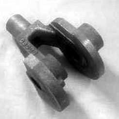
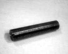
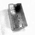
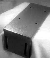
3 NOTICE Parts illustrated, and listed by number on the following pages, are for the latest model Modern Electronics & Equipment Pecan Cracker. When ordering replacement parts, please give serial number of your Pecan Cracker, plus the following additional information when ordering Cracking Box Yoke, C-2251 or Slide Plate, C-4165: Cracking Box Yoke, show diameter of pins, 1/2, 9/16, or 5/8. Slide Plate, show thickness of bottom plate, 3/8 or 1/2. Please Note: Crackers after serial number 945 are considered New Type, shipped slot of the Sprocket Idler Shaft, C Turn Sprocket Idler Shaft in clockwise direction until proper clearance is obtained; if necessary, remove the four cap screws in the Chain Adjustment Cap, C-2030, to advance to the next Nut Pocket. NEVER TURN FEED CHAIN COUNTER-CLOCKWISE TO MAKE FEED CHAIN ADJUSTMENTS. After proper clearance is obtained, tighten or reinstall the four cap screws in the Chain Adjustment Cap. Next, turn the Cracker by hand through two complete cycles to make sure the Cracking Box Die to Nut Pocket clearance is correct. If clearance is correct, operate machine. To Change Nut Pockets: Insert T-handled Wrench, C-2142, provided into socket head screws which fasten Nut Pockets to Feed Chain. Loosen screws, then remove Nut Pockets and replace with desired size Nut Pocket. In changing from one size set of Nut Pockets to another size, it is also necessary to remove the Tongue Casting** located at the bottom of the Nut Hopper. Also remove the Cracking Box Die (see next paragraph). To remove Tongue Casting unscrew 3/8" cap screw, then slide casting out of machine. After the Nut Pockets have been changed, check the clearance with the Cracking Box Die and if necessary adjust as in preceding instructions. ** #11 and #13 Nut Pockets use Tongue Casting C-2087 while #15 and #18 Nut Pockets use Tongue Casting C Refer to Drawing C To Remove Cracking Box: Unscrew Knockout Rod Bushing, C-2054, at the rear of the machine and remove the Knockout Rod, C-2420-B. Remove Cracking Box Slide Cover, C-6009, unscrew Drive Stud, C-2287, and lift the box out. After the Cracking Box has been removed, it can be clamped in a vise, taking care that clamping force is applied only to the bottom plate of the box. The Die Rack Spring may then be removed by removing the Die Rack Spring Nut. Use the T-Handle allen wrench supplied to hold pressure against the Die Rack Spring Nut as you unscrew it. Then ease the spring pressure off and remove Die Rack Spring. Failure to use caution in disassembling Cracking Box will cause bodily harm. Cracking box and all parts should be cleaned in a suitable cleaning fluid, such as kerosene, and dried. Care should be taken that the small hole in the center of the Die Rack, C-4024, leading to the Cracking Die is cleaned of all dust and fine shell. This can be done by using a small round brush which can be passed through the hole. In reassembling parts in the Cracking Box, care should be taken that parts are replaced in their proper working positions. Special attention should also be given to the Pawl Spring Adjustment Assembly, to make sure that Pawl Spring Guide C-2311 is assembled in spring and pawl alignment plug as shown below. Parts should be re-lubricated as they are reassembled in the Cracking Box. After assembly of all parts, including Cracking Box Cover, C-2180, the Cracking Box can be replaced in the Cracker Frame and the Connecting Arm, C-2281, connected to the Drive Gear, C-4008, by inserting and tightening the Drive Stud, C The Slide Cover can then be replaced and reassembly is complete. Drawing C-2728 C-2311 Pawl Spring Guide Pawl Alignment Spring C-2412 C-2312 Pawl Alignment Plug IMPORTANT: When reassembling a Cracking Box, be sure that Pawl Spring Guide, C-2311, Pawl Alignment Spring, C-2412, and Pawl Alignment Plug, C-2312, are assembled as shown to insure proper operation. To Change Cracking Box Die: Remove Cracking Box Slide Cover Assembly, C-6008-A, turn Drive Pulley, C-4507, counter-clockwise until Cracking Box is at the rear of machine, then place a punch against the shoulder of back of the die and drive forward and out. For correct combination of Nut Pockets, Tongue Casting and Cracking Die, refer to Drawing C-6108 on the back page of the Manual. Position the tapered end of the Cracking Box Die into the end of the Cracking Box Die Rack, C-4024, with clean-out hole in the die facing the floor. Also the number stamped on the die should face the installer. Turn the Drive Pulley, C-4507, counter-clockwise until Cracking Box is at the the front of the machine. Lift Inspection Door, C-2036, insert brass rod through Inspection Door opening until it contacts the Cracking Box Die. Then use a hammer to drive the Cracking Box Die into the Die Rack. Carrier Chain Oil Cup: The red cup, on the front of the Pecan Cracker, MUST BE FILLED EACH DAY while the Cracker is in operation. Periodic inspection of the Carrier Chain should be made by removing the Inspection Cover, C-4020, on the front of the Feed Chain Plate, C-8008-A. A properly lubricated Carrier Chain should ride freely in a straight vertical line between sprockets. If the Chain shows a tendency to buckle, it is not receiving sufficient lubrication. In such instance, additional oil should be applied to the Carrier Chain until it runs free. If this oil cup remains full, cup and tubing should be immediately checked for possible clogging. Insufficient lubrication will result in excessive chain wear, binding of chain, and mis-alignment of Nut Pockets with Cracking Box Die. Removing Stationary Die Knockout Rod: Refer to Drawing C Simply loosen Lock Nut, C-2075, and the entire assembly can be removed by unscrewing the Adjusting Screw. Drawing C-2440 Note A: For proper crack, follow directions as outlined in paragraph labeled "To Set Crack Adjustment". Adjust Pecan Cracker just hard enough to crack shell completely around all nuts. Note B: When reassembling chain, make sure that Nut Pocket attachment holes are on bottom ends of chain links on cracking side of unit. Refer to Drawing C Safety Guidelines: The Modern Electronics Pecan Cracker comes equipped with Protective Guards. DO NOT OPERATE THIS MACHINE WITHOUT PROTECTIVE GUARDS IN PLACE. Stop the Pecan Cracker before performing maintenance and before performing any other activities that will require removal of Protective Guards. Stop the Cracker before reaching inside the machine with body parts (i.e. hands, fingers, etc.) or tools. Failure to follow these guidelines can result in severe injury or even death. Unless otherwise specified, before operating this machine, alert employees of safety guidelines. As always, common sense and direct and clear instruction will keep everyone safe. Page 2


 Goes thru Casting with 2 Cotter Keys-")
 Has Bushing that Screws in with")

 * Not")


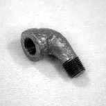
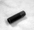
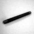
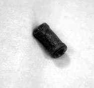
4 Cracker Box Parts C-2108 C-2288-C C-2057 C-2132 #132 #194 C-2726-D C-2251-C C-2104 C-2134 C-4024-B Each Cracking Box Die is inserted at the Circled Area. C-2180 #188 C-2060 C-2407 C-2454-D C-2424 **C-4165-B C-2423 C-2312 C-2412 C-2311 ***C-6042 C-2281 C-2421 C-2054 C C-2076 #130 #119 C-2287 C-2420-B #133 C-2054 Cracking Box Rod Bushing C-2057 #18 Cracking Box Die C-2060 Crack Adjustment Spring Holder C-2076 Carriage Spring Plug C-2104 #13 Cracking Box Die C-2108 Square Yoke Bushing, for ½" Slide Plate C-2132 #11 Cracking Box Die C-2134 #15 Cracking Box Die C-2180 Cracking Box Cover with (4) #132 Screws C-2251-C Cracking Box Yoke C-2281 Connecting Arm *C-2282-A Rear Die Block without Tubes and Holes *C-2282-B Rear Die Blockwith Holes, Machined with C-2422 & C-2283 *C-2283 Carriage Spring Holder Welded to C-2282 *C-2284 Wrist Pin Block *C-2285 Front Die Block *C-2286 Adjustment Spring Guide C-2287 Drive Stud C-2288-C Tapered Pawl 5/8 : A=½, B=9/16 C-2311 Pawl Spring Guide C-2312 Pawl Alignment Plug C-2407 Crack Adjustment Spring C-2412 Pawl Spring *C-2420-A Cracking Box Knockout Rod (Old) Goes thru Casting with 2 Cotter Keys- No Photo C-2420-B Cracking Box Knockout Rod (New) Has Bushing that Screws in with Collar C-2421 Wrist Pin, New Type C-2423 Die Rack Spring Nut C-2424 Die Rack Spring Guide C-2454-D Die Rack Spring C-2455 Carriage Spring (Slide Return) * Not Pictured ** C-4165-A Slide Plate, 3/8" NO LONGER AVAILABLE - Must Purchase Conversion Kit Consisting of: C-2108-A, C-2251-C, C-2288-C, C-2726-D, C-4024-B, andc-4165-b. *** C-6042 Cracking Box Frame is available as one part. It consists of C-2282 Rear Die Block, C-2283 Carriage Spring Holder, C-2284 Wrist Pin Block, C-2285 Front Die Guide, and C-2286 Adjustment Spring Guide. Page 3 C-2726-D Square Yoke Bushing, State Size of Bore: ½, 9/16, 5/8 C-4024-B Cracking Box Die Rack for ½ Slide Plate **C-4165-B Slide Plate, Thickness of Bottom Plate: ½" ***C-6042 Cracking Box Frame *C-7776 Cracking Box Assembly *C-7776-H Cracking Box Assembly, Heat Treated #130 3/8" x 7/8" SAE Allen Head Dog Point Set Screw #119 3/8" SAE Lock Nut #132 ¼" x ¾" Flat Head or Socket Cap Screws #133 1/8" x ¾" Cotter Key #188 #4 x 1-5/8" Taper Pin #194 5/16 x 3/4 Dowel Pin *#195 1/4 x 1/2 Socket Head Cap Screw


")


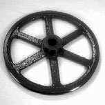
5 Cracker Frame Parts #161 #160 #159 #124 #134 C-2105 #137 #135 #136 C-2070 C-2068 C-2031 C-2030 C-2071 #139 #138 #163 #120 #189 #154 #153 #151 #150 #162 C-2137 C-2073-B C-2069 #144 C-4008 #143 #141 C-2072-A #193 #148 #154 #153 #152 #155 #147 C-4507 C-2099 #157 C-2098 C-2096 C-2262 C-2411 C-2066 #142 #140 Cracker Frame (with bushings) C-2030 Chain Adjustment Cap with #189 Key C-2031 Sprocket Adjustment Bearing with #189 Key C-2066 Cracker Drive Shaft C-2068 Lower Chain Sprocket, 20 Tooth with #189 Key C-2069 Drive Shaft Gear, 30 Tooth with #147 Key C-2070 Sprocket Shaft Gear, 30 Tooth with #120 Taper Pin C-2071 Sprocket Drive Shaft with #120 Taper Pin *C-2072 Pinion Shaft Only with #193 Taper Pin C-2072-A Pinion Gear and Shaft Assembly *C-2072-B Pinion Gear Only with #193 Taper Pin *C-2073-A Feed Chain Drive Shaft with #148 Taper Pin (Old 18-7/8") C-2073-B Feed Chain Drive Shaft with #148 Taper Pin (New 19-5/8") * Not Pictured C-2096 Eccentric Washer C-2098 Vibrator Eccentric C-2099 Vibrator Shaft with C-2097 Connector C-2105 Stationary Die C-2137 Bronze Worm Gear-Hub out or in with #148 Taper Pin C-2262 Drive Shaft Pin C-2411 Steel Worm, Hardened & Polished C-4008 Drive Gear C-4507 Drive Pulley #120 #7 x 2" Taper Pin #124 Oil Pipe, 1-1/4" Long #134 3/8" x 3/8" Allen Head Set Screw #135 1" x 1-1/4" x 2-1/4" Bronze Bushing # /2" x 1-3/4" x 1-1/2" Bronze Bushing #137 5/8" Hex Nut #138 7/16" x 5/8" x ¾" Bronze Bushing # /4" x 1" x 2-1/2" Bronze Bushing #140 3/4" x 1" x 2" Bronze Bushing #141 3/4" x 1" x 1-3/4" Bronze Bushing #142 7/8" x 1-1/8" x 1-3/4" Bronze Bushing #143 7/8" x 1-1/8" x 2" Bronze Bushing #144 1" x 1-1/4" x 3" Bronze Bushing #147 ¼" x ¼" x 1-3/4" Key #148 #7 x 1-3/4" Taper Pin #150 7/16" x 1" x 3/16" Washer #151 7/16" x 1-1/4" Hex Head Cap Screws #152 3/8" x 3/8" Allen Head Set Screw #153 3/8" x 5/8" Square Head Set Screw #154 3/8" x ½" Square Head Set Screw #155 #19 x 3/16" x 1-1/4" Woodruff Key #157 3/8" Acorn Nut #159 Oil Pipe, 3-1/4" Long #160 Oil Pipe, 4-1/4" Long #161 Oil Pipe, 8-1/2" Long #162 GIts Oil Cup, #325 #163 Plug #189 ¼" x 1-1/4" Key #193 #4 x 1-1/4" Taper Pin Page 4


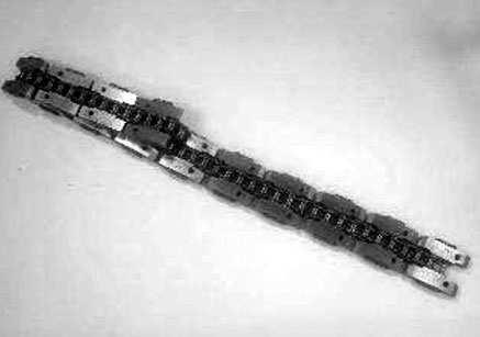
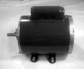
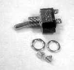


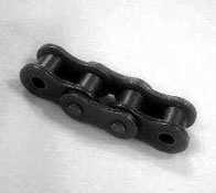
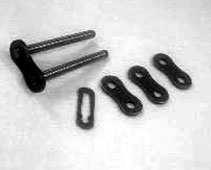
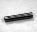
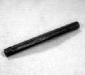

6 Cracker Drive Parts #109 #108 #107 C-2403 C-2582 #101 #103 #105 #106 #102 #104-A C-2409 C-4025 C-2395 C-4128-A C-2577, C-2142 C-2141 #123 #118 C-2067 C-2074 C-6036-A #145 #146 #110 C-2293 #119 C-2075 #113 #115 #117 #128 #129 C-4021 #114 #116 #194 C-4652 C-2037 C-2037 Left Right C-2049 C-2394 C-2410 C-2944 C-2050 C-2032 C-2085 C-2086 C-2027 C-2087 #112 #111 C-4460 #120 #121 #122 #124 #125 #191 #192 C-2027 #13 Nut Pocket C-2032 #18 Nut Pocket C-2037 Chain Bar, Right Hand C-2037 Chain Bar, Left Hand C-2049 Chain Adjustment Pin C-2050 Crack Adjustment Screw C-2067 Top Chain Sprocket, 20 Teeth with #120 Taper Pin C-2074 Sprocket Idler Shaft with #120 Taper Pin C-2075 Knockout Rod Screw and Nut C-2085 #11 Nut Pockets C-2086 #15 Nut Pockets C-2087 #11, #13 Tongue Casting C-2141 Feed Chain Wrench C-2142 Nut Pocket Wrench C-2293 Stationary Die Knockout Rod Tip C-2394 Chain Adjustment Nut C-2395 Stationary Die Knockout Rod Sleeve C-2403 Motor Bracket C-2409 Stationary Die Knockout Rod Spring C-2410 Chain Yoke Washer C-2577 Die Rack Spring Wrench C-2582 Vertical-Horizontal Brace Plate * Not Pictured C-2944 Chain Yoke Washer C-4021 Lower Chain Bracket C-4025 Lock Pin C-4128-A Stationary Die Knockout Rod *C-4128-B Stationary Die Knockout Rod Assembly C-4460 #15, #18 Tongue Casting C-4652 Feed Chain Assembly without Nut Pockets C-6036-A Chain Yoke Assembly with (2) #118 #101 1/3 HP Master Motor, Volt #102 Motor Pulley with #107 #103 Motor Switch Box *#104 Motor Switch & Circuit Breaker Assembly #104-A Toggle Switch #105 8 Amp Fuse *#105-A 10 Amp Circuit Breaker #106 Motor Cord Clamp #107 Motor Pulley Key #108 V Belt #109 Motor Cord (14/3 Wire) #110 Motor Cord Male Plug (3 Prong) #111 5/16" x 1-1/2" Socket Head Cap Screw #112 3/8" x 1-1/2" Hex Cap Screw #113 3/8" x 2" Hex Head Cap Screw #114 3/8" x 1" Hex Head Cap Screw #115 3/8" x 1½" Square Head Set Screw #116 3/8" x ½" Square Head Set Screw #117 5/16" x 1½" Dowel Pin #118 1" x 1-1/4" x 1-3/4" Bronze Bushing #119 3/8" SAE Lock Nut #120 #7 x 2" Taper Pin #121 Oil Pipe, 4-1/4" Long #122 Street Ell - 1/8" Pipe #123 Oil Pipe, 2-1/4" Long #124 Oil Pipe, 1-1/4" Long #125 Gits Oiler 5/16, #325 #128 Chain Section #129 Chain Pin Link #145 3/8 x 1 Hex Head Cap Screws #146 3/8 Lock Washer #191 4" Oil Pipe # Elbow #194 5/16" x ¾" Dowel Pin Page 5


 *C-6008-A")


7 Cracker Cover Parts #125 #171 #179 C-4023 #186 #187 C-4039 C-4038 C-4522-B C-6007 C-4020 #165 #172 #180 #166 #173 #181 C-2036 #167 #174 #183 C-2400 #169 #177 C-8007-A C-8008-A #184 #170 #178 C-2943 C-8009 C-2942 #182 C-9705 C-6008 #176 C-6009 C-6020-B C-2036 Inspection Door C-2400 Inspection Door Weight C-2942 Left Hand Nut Pocket Guide C-2943 Right Hand Nut Pocket Guide C-4020 Inspection Plate C-4023 Name Plate C-4038 Nut Guide Strip, Right C-4039 Nut Guide Strip, Left C-4522-B Worm Gear Guard, New Type C-6007 Rear Leg C-6008 Drive Gear Cover (New Only) *C-6008-A Drive Gear Cover/Slide Cover Assembly C-6009 Slide Cover with (2) #177 C-6020 Sheet Metal Belt Guard C-8007-A Feed Chain and Hooper Bracket C-8008-A Feed Chain Plate C-8009 Front Leg C-9704 Hopper Base C-9705 Hopper Top #125 Gits Oil Cup, #325 #165 5/16" x 1-1/4" Round Head Screw #166 3/8" x 1" Hex Head Cap Screw #167 3/8" x 1" Fillister Head Screw #169 3/8" x 2" Hex Head Cap Screw #170 5/16" x 5/8" Round Head Machine Screw #171 3/8" x 1" Hex Head Cap Screw #172 5/16" x ¾" Dowel Pin #173 Gits Oil Cup, #325 #174 3/8" x ¾" Round Head Bolt C-9704 #176 Gits Oiler with Copper Tubing #177 #10 x 5/8 Rivets #178 3/8" x ¾" Hex Head Cap Screw #179 ¼" x 5/8" Flat Head Screw #180 5/16" x ¾" Hex Head Cap Screw #181 ¼" x ½" Flat Head Screw #182 Chain Oiler with Copper Tubing and 40 or 45 Elbow #183 1/16" x ½" Cotter Pin #184 3/16" x 1-1/8" Dowel Pin *#185 1/16" Flat Washer #186 ¼" x 5/8" Flat Head Screw #187 ¼" x ½" Flat Head Screw * Not Pictured Page 6
8 Drawing C-6108 Tongue Casting (Refer to Table C-1) C-2068 C-2031 C-2030 C-2059 C-2071 C-2050 C-2074 C-2141 C-6036 C-2410 C-2394 C-4021 C-2049 C-2142, C-2577 C-4128 C-2293 C-2105 C-2037 C-2067 #117 C-2312 C-2180-A Cracking Die (Refer to Table C-1) C-2075 C-2060 C-2072 C-2726 C-2288 C-2099 C-2073 C-2098 C-6042 Nut Pocket (Refer to Table C-1) C-2137 C-6042 C-2409 C-4024 C-2281 C-2407 Tongue Casting C-2087 C-2087 C-4460 C-4460 C-2097 C-2096 C-2066 C-2411 C-2251-C C-4165-A C-2454 C-2311 C-2412 Cracking Die C-2132 C-2104 C-2134 C-2057 TABLE C-1 Nut Pocket C-2085 C-2027 C-2066 C-2032 C-2423 C-2422 C-2421 C-2395 #132 C-2108 Pecan Size #11 #13 #15 #18 C-2287 C-4008 Nut Pocket Machining C-4248 C-4249 C-4250 C-4251 C C-2424 C-2076 (Plug in front of Spring) C-2054 C-2283 Phone: Fax: Located: 280 Independence Ave., Grand Cane, Louisiana Mailing: PO Box 817, Mansfield, Louisiana
400A 40113V, 401A 40120V, & 401AL 40120VL ALUMINUM VERTICAL 4000 LB LIFT INCLUDES SCREW LEG ASSEMBLY INSTRUCTIONS
 12/11/07 PAGE 1 OF 12 400A 40113V, 401A 40120V, & 401AL 40120VL ALUMINUM VERTICAL 4000 LB LIFT INCLUDES SCREW LEG ASSEMBLY INSTRUCTIONS Thank you for purchasing our product! *Please read these instructions
Horizontal and Vertical. Metal Cutting Band Saw MODEL: BS-115
 Horizontal and Vertical Metal Cutting Band Saw MODEL: BS-5 SAFETY. Know your band saw. Read the operator s Manual carefully. Learn the operations, applications and limitation.. Use recommended accessories.
HYDRAULIC CONTROL DETAILS PARTS LIST
 Always give model number, serial number and part number when ordering repair parts. HYDRAULIC CONTROL DETAILS PARTS LIST REF NO. PART NUMBER DESCRIPTION 1 101939 Hydraulic Tank 2 101940 Hydraulic Tank
INSTRUCTION MANUAL AND PARTS LIST MODEL 14-10
 VERTICAL BAND SAWS INSTRUCTION MANUAL AND PARTS LIST MODEL 1-10 DAKE/PARMA WHEN ORDERING PARTS GIVE COMPLETE SERIAL NUMBER OF MACHINE GIVE PART NUMBER AND NAME GIVE AMOUNT REQUIRED Unless the above data
SERIES I MILLING MACHINES
 INSTALLATION, OPERATION, MAINTENANCE, AND PARTS LIST SERIES I MILLING MACHINES TP5260 Revised: August 29, 2005 Manual No. M-450 Litho in U.S.A. Part No. M -0009500-0450 June, 2003 MAINTENANCE PROCEDURES
Operating Instructions For Lockformer Button Punch Flanger
 Capacity: 20 to 28 Gauge Galvanize Operating Instructions For Lockformer Button Punch Flanger To satisfactorily form the 90º button punch flange on light gauge materials, it was necessary to form the metal
Geology, Prospectors, Mining, Metallurgy, Assaying, Environmental, Geotechnical
 LEGEND INC. Geology, Prospectors, Mining, Metallurgy, Assaying, Environmental, Geotechnical 988 Packer Way Sparks, NV 89431 Tel: (786) 786-3003 Fax: (775) 786-3613 Email: info@lmine.com Web: www.lmine.com
Thank you for purchasing our product! *Please read these instructions and follow them step by step.*
 07/07/08.rev1 PAGE 1 OF 11 601AL VERTICAL 60120VL LIFT W/CHAIN DRIVE WINCH Thank you for purchasing our product! *Please read these instructions and follow them step by step.* Step 1. Separate and group
Inspection. Assembly Install the springs. 1. Discard the 0-rings. 2. Clean all parts in cleaning solvent.
 6010-34 Inspection 3. Install the springs. 1. Discard the 0-rings. 2. Clean all parts in cleaning solvent. 3. If spring test equipment is available, check the tension of each spring according to the specifications
200A FLB VERTICAL 22113V LIFT W/CHAIN DRIVE WINCH
 PG. 1 OF 11 PORTA-DOCK, INC. 200A FLB VERTICAL 22113V LIFT W/CHAIN DRIVE WINCH STEP 1. Separate and group like parts and fasteners together. Locate the winch side member with the longer upright tube and
N. 15th Street, Middlesboro, KY FLIP TARP DUMP BODY INSTALLATION INSTRUCTIONS
 1-800-248-7717 1002 N. 15th Street, Middlesboro, KY 40965 FLIP TARP DUMP BODY INSTALLATION INSTRUCTIONS Congratulations on your purchase of a Mountain Flip Tarp Dump Body tarping system. With tarping systems
SERVICE PARTS LIST PAGE 1 OF 6 BASE ASSEMBLY SPECIFY CATALOG NO. AND SERIAL NO. WHEN ORDERING PARTS 12" SLIDING COMPOUND MITER SAW
 PAGE 1 OF 6 BASE ASSEMBLY 00 0 CATALOG NO. EXAMPLE: SPECIFY CATALOG NO. AND NO. WHEN ORDERING PARTS 6955-20 1 02-80-0050 Thrust Bearing (1) 2 05-80-0510 M5 x 12mm Flat Head T-20 Screw (5) 3 05-81-0135
4.4 PUMP MAINTENANCE MODELS: DB, DC, DF, DG, DJ, DL
 4.4 PUMP MAINTENANCE MODELS: DB, DC, DF, DG, DJ, DL 4.4.1 EXPLODED VIEW DRAWING REF. QTY. DB DC DF DG DJ DL DESCRIPTION PART # 1 1 ADAPTOR FRAME 034007 2 12 LOCK WASHER 3/8 x 1/8 S.S. 034004 3 12 HEX HEAD
SECTION 9: PARTS. Headstock A 126A 127A-1 REF PART # DESCRIPTION REF PART # DESCRIPTION
 SECTION 9: PARTS Headstock 120 121 113 115 112 111 110 109 108 105 106 107 135 101 119A 121 120 118 114 115 107 106 104 123 122 118 114 126A 105 126 103 102 126B 127A-1 131 127A 124 133 134 126C 129 130
Feed Drawer Rebuild, for Models, 22HF, 16HF, 1600 machines
 Knowledge Base Article Type: Instructions Feed Drawer Rebuild, for Models, 22HF, 16HF, 1600 machines Description: Instructions on How to properly remove and rebuild a Feed Drawer. WARNING Never work on,
Cam Handle Service Guide
 Cam Handle Service Guide Page 2. Introduction Page 3. Troubleshooting guide Page 4-5. Adjusting the clamp force Page 6-7. Disassembling, greasing and replacing components Page 8-9. Replacing the post bearings
ABM International, Inc. Navigator Assembly Manual
 ABM International, Inc. 1 1.0: Parts List Tablet (Qty. 1) Tablet mount (Qty. 1) NOTE: Mount may appear and operate different then image below Control Box (Qty. 1) Motor Power Supply (Qty. 1) 2 X-axis motor
Di-Acro 18E Stylus Turret Punch Press
 OPERATOR S MANUAL & INSTRUCTIONS Di-Acro E Stylus Turret Punch Press Di-Acro, Incorporated PO Box 00 Canton, Ohio Progress Street N.E. Canton, Ohio 0 0-- 0--00 (fax) Revised 0/0 Sale or distribution of
Operating Instructions
 Operating Instructions Holding the material against the angle gauge slide it into the forming head. Be sure that the material remains against the gauge until work is finished. NOTE: This machine will handle
Maintenance & Parts list for:
 Maintenance & Parts list for: Industrial gun GB 2 Juni 2017 This Maintenance & Parts list for industrial gun is prepared by : Winchester Europe Service V. Parbst & Søn as a comprehensive maintenance guide
Lumber Smith. Assembly Manual. If you are having problems assembling the saw and need assistance, please contact us at:
 Lumber Smith Assembly Manual If you are having problems assembling the saw and need assistance, please contact us at: 804-577-7398 info@lumbersmith.com 1 Step 1 Safety Carefully read the Owners Manual.
STARTING SERIAL NUMBER PARTS LIST FOR. Wellsaw MODEL 600 METAL CUTTING BAND SAW
 STARTING SERIAL NUMBER 11075 PARTS LIST FOR Wellsaw MODEL 600 METAL CUTTING BAND SAW Wellsaw 2829 N. Burdick, Kalamazoo, MI 49004 Phone: 269-345-1132 Fax: 269-345-0095 Rev 171005 INSTALLATION, OPERATION
Bead Roller Operating, Servicing, and Safety Instruction Manual
 Bead Roller Operating, Servicing, and Safety Instruction Manual CAUTION: Read and Understand These Operating, Servicing, and Safety Instructions, Before Using This Machine. 1-800-67-26 10 Cooperative Way
RYOBI 10 IN (254 MM) TABLE SAW MODEL NO. BT REPAIR SHEET
 TABLE SAW MODEL NO. BT REPAIR SHEET") RYOBI 0 IN (2 MM) TABLE SAW MODEL NO. BT00- REPAIR SHEET 2 RYOBI 0 in. (2 mm) TABLE SAW - MODEL NO. BT00- FOR MITER TABLE ASSEMBLY, REFER TO FIGURE B FOR BLADE GUARD ASSEMBLY, REFER TO FIGURE E FOR RIP
RYOBI 0 IN (2 MM) TABLE SAW MODEL NO. BT00- REPAIR SHEET 2 RYOBI 0 in. (2 mm) TABLE SAW - MODEL NO. BT00- FOR MITER TABLE ASSEMBLY, REFER TO FIGURE B FOR BLADE GUARD ASSEMBLY, REFER TO FIGURE E FOR RIP
PARTS LIST: Air Control Assembly (1632 Sander)
") PARTS LIST: Air Control Assembly (1632 Sander) 1 6293482 Filter... 1 2 6293483 Solenoid Valve... 1 3 6293484 Brake Cylinder... 1 4 6293485 Multi-Hole Connector... 1 5 6293486 Air Valve... 1 6 6293487 Air
PARTS LIST: Air Control Assembly (1632 Sander) 1 6293482 Filter... 1 2 6293483 Solenoid Valve... 1 3 6293484 Brake Cylinder... 1 4 6293485 Multi-Hole Connector... 1 5 6293486 Air Valve... 1 6 6293487 Air
CNC Router Parts. Standard Rack & Pinion Drive Assembly Instructions
 CNC Router Parts Standard Rack & Pinion Drive Tools List The following tools will be used for assembly and installation of the Standard Rack & Pinion Drive: Imperial Allen Wrench Set - 3/32", 5/32", 3/16",
PowerLock. Installation Instructions. Attention Dealers: Please give this owners manual to the customer when the product is delivered.
 Serving the Truck & Trailer Industry Since 1944 FOR Attention Dealers: Please give this owners manual to the customer when the product is delivered. Call 800-535-9545 www.aeroindustries.com Indianapolis,
HA-2 INDUSTRIAL UNDERCUTTER INSTRUCTIONS. Caution!
 HA-2 INDUSTRIAL UNDERCUTTER INSTRUCTIONS Caution! The Outrigger Assembly MUST be supported and the Pawl Finger, on the Safety Pawl, engaged in the rack BEFORE loosening the two (2) Clamping Bolts. Personal
Ringblaster Mark IV Maintenance Guide. Version 1.5
 Ringblaster Mark IV Maintenance Guide Version 1.5 WARNING Winchester Industrial Equipment and Loads must be properly stored, handled and maintained for safe and proper function. Mishandling or failure
SECTION 9: PARTS. Table Breakdown REF PART # DESCRIPTION REF PART # DESCRIPTION
 SECTION 9: PARTS Table Breakdown 1 2 3 4 5 6 7 8 9 10 11 12 13 14 15 16 17 18 19 20 21 22 23 24 23 25 17 26 27 8 1 P0675001 CAP SCREW M8-1.25 X 30 15 P0675015 SUPPORT BLOCK 2 P0675002 TABLE SUPPORT BLOCK
Coolant Tank Screen Leg Idle End Lockwasher 64 B-015B Leg Drive End Machine Screw 1/4-20 x 3/4 Round Head
 Always give model number, serial number and part number when ordering repair parts. BED, COOLANT & DASH POT PARTS LIST (Cont'd.) REF NO. PART NUMBER DESCRIPTION 19 B-077 Vise Slide Block 20 B-045 Vise
SERVICE PARTS LIST PAGE 1 OF 6 BASE ASSEMBLY SPECIFY CATALOG NO. AND SERIAL NO. WHEN ORDERING PARTS 12" DUAL BEVEL COMPOUND MITER SAW B27B
 PAGE 1 OF 6 BASE ASSEMBLY 00 0 EXAMPLE: Component Parts (Small #) Are Included When Ordering The Assembly (Large #). SPECIFY CATALOG NO. AND NO. WHEN ORDERING PARTS = Part number change from previous service
TO OPERATE AUTO-GUIDE POWER. 24 Gauge Pittsburgh Operating Instructions FLANGING ATTACHMENT
 24 Gauge Pittsburgh Operating Instructions Holding the material against the angle gauge slide it into the forming head. Be sure that the material remains against the gauge until work is finished. Make
Operating, Servicing, and Safety Manual Model " Foot Shear CAUTION: Read and Understand
 Operating, Servicing, and Safety Manual Model 3000 52" Foot Shear CAUTION: Read and Understand These Operating, Servicing, and Safety Instructions, Before Using This Machine. SAFETY The purpose of the
JARVIS. Model H080 Carcass Splitting Band Saw
 Carcass Splitting Band Saw EQUIPMENT SELECTION... Ordering No. TABLE OF CONTENTS... Page... See Table 1, Page 4 Balancer... 4042042 Band Saw Blade... 1023099 Notice to Employer and Safety Director... 2
RYOBI 10 in. (254 mm) TABLE SAW MODEL NO. BT3100 REPAIR SHEET
 TABLE SAW MODEL NO. BT3100 REPAIR SHEET") RYOBI 0 in. (4 mm) TABLE SAW MODEL NO. BT00 REPAIR SHEET FOR MITER TABLE ASSEMBLY, REFER TO FIGURE B FOR BLADE GUARD ASSEMBLY, REFER TO FIGURE E FOR RIP FENCE ASSEMBLY, REFER TO FIGURE C FOR MOTOR ASSEMBLY,
RYOBI 0 in. (4 mm) TABLE SAW MODEL NO. BT00 REPAIR SHEET FOR MITER TABLE ASSEMBLY, REFER TO FIGURE B FOR BLADE GUARD ASSEMBLY, REFER TO FIGURE E FOR RIP FENCE ASSEMBLY, REFER TO FIGURE C FOR MOTOR ASSEMBLY,
MODEL 36 Di-Acro Hand Shear
 OPERATOR S MANUAL & INSTRUCTIONS MODEL 36 Di-Acro Hand Shear Di-Acro, Incorporated PO Box 9700 Canton, Ohio 44711 3713 Progress Street N.E. Canton, Ohio 44705 330-455-1942 330-455-0220 (fax) Revised 01/02
Operating Instructions and Parts Manual 10-inch Table Saw
 Operating Instructions and Parts Manual 10-inch Table Saw Model 66 shown with optional extension table and legs, mobile base, and motor cover WMH TOOL GROUP 2420 Vantage Drive Elgin, Illinois 60123 Part
FLIP TARP SINGLE & DOUBLE UNDERBODY TRAILERS
 1-800-248-7717 1002 N. 15th Street, Middlesboro, KY 40965 FLIP TARP SINGLE & DOUBLE UNDERBODY TRAILERS INSTALLATION INSTRUCTIONS Congratulations on your purchase of a Mountain Flip Tarp Trailer system.
Exploded View Saw Base - Model 7060 Semi-Automatic Cut-Off Band Saw
 Exploded View Saw Base - Model 7060 Semi-Automatic Cut-Off Band Saw 136 137 135 134 132 131 133 113 114 115 117 116 118 119 120 121 79 78 77 107 108 65 76 110 109 66 10 9 6 11 5 4 8 7 75 74 73 72 111 112
PowerLock. Installation Instructions. Attention Dealers: Please give this owners manual to the customer when the product is delivered.
 Serving the Truck & Trailer Industry Since 1944 PowerLock Attention Dealers: Please give this owners manual to the customer when the product is delivered. Call 800-535-9545 www.aeroindustries.com Indianapolis,
Model: SCD430 SCD640. Installation & Operation Guide P/N SCD640-95
 Model: SCD430 SCD640 Installation & Operation Guide P/N SCD640-95 Model SCD430 and SCD640 Kurt has two Self-Centering vises, a four-inch jaw width (SCD430) and a six-inch jaw width (SCD640). Jaw opening
24 GA. PITTS ROLLFORMER
 1 TIN KNOCKER 24 GA. PITTS ROLLFORMER INSTRUCTIONS & PARTS DIAGRAM Shown with Stand and Optional Flanging Attachment Rev. 092606 TAAG MACHINERY CO. (Master Distributor) 1257-B Activity Dr. Vista, CA 92081
ITEM NO. PART NO DESCRIPTION QTY.
 PUMP MAINTENANCE ITEM NO. PART NO DESCRIPTION QTY. 1 52002 Center Case 1 2 52052 Back End Plate 1 3 52051 Front End Plate 1 4 55090 Octagonal Nut 1 5 53001 Idler Gear 1 6 53002 Drive Gear 1 7 28062 Bushing
OPERATING INSTRUCTIONS 3421UX VETERANS BLVD, CARLSTADT, NJ 07072
 OPERATING INSTRUCTIONS 3421UX5-1 400 VETERANS BLVD, CARLSTADT, NJ 07072 CONTENTS DESCRIPTION... 3 OPERATOR INFORMATION... 5-8 INSTALLATION...... 4 ADJUSTMENT... 8-17 LUBRICATION... 5 INDEX Description
 488 PARTS LIST 1 3 SCREWS FOR NO. 2 2 FLYWHEEL CAP 3 FLYWHEEL 4 END NUT FOR NO. 10 5 BALL BEARING FOR NO. 3 (1 st ) 6 BALLBEARING FOR NO. 3 (2nd) 7A CLUTCH RACE KEY 7B CLUTCH RACE 7C CLUTCH SPRING 7D 7
VARIABLE SPEED WOOD LATHE. Model DB900 INSTRUCTION MANUAL
 VARIABLE SPEED WOOD LATHE Model DB900 INSTRUCTION MANUAL 1007 TABLE OF CONTENTS SECTION...PAGE Technical data.. 1 General safety rules....1-3 Specific safety rules for wood lathe.....3 Electrical information.4
REPAIR INSTRUCTIONS. Cat. No Cat. No MILWAUKEE ELECTRIC TOOL CORPORATION. SDS Max Demolition Hammer. SDS Max Rotary Hammer
 Cat. No. 9-0 SDS Max Demolition Hammer Cat. No. -0 SDS Max Rotary Hammer MILWAUKEE ELECTRIC TOOL CORPORATION W. LISBON ROAD BROOKFIELD, WISCONSIN 00-0 8-9-0 d 000 8-9-0 d Special Tools Require Forcing
M2 Assembly. M2 Sub-Assemblies mm Belt Sub-Assembly mm Belt Sub-Assembly Spider Sub-Assembly... 4
 M2 Assembly Table of Contents M2 Sub-Assemblies... 3 630mm Belt Sub-Assembly... 3 702mm Belt Sub-Assembly... 3 Spider Sub-Assembly... 4 Idler Bolt Sub-Assembly... 8 Y Motor Sub-Assembly... 9 X Motor Sub-Assembly...
400 SERIES GRINDER PUMPS 41502, 42202,43302, AND MODELS
 Section: MOYNO 500 PUMPS Page: 1 of 6 Date: March 1, 1998 SERVICE MANUAL MOYNO 500 PUMPS 400 SERIES GRINDER PUMPS 41502, 42202,43302, AND 44402 MODELS DESIGN FEATURES Housing: Cast iron Pump Rotor: Chrome
HD installation guide
 JANUS INTERNATIONAL 1 866 562 2580 www.janusintl.c o m 1950 1950HD installation guide RIGHT DRIVE END SHOWN LH OPPOSITE LEFT TENSION END SHOWN RH OPPOSITE PUSH-UP OPERATION 1950 1950HD SHOWN A rolling
PowerLock. Installation Instructions. Attention Dealers: Please give this owners manual to the customer when the product is delivered.
 Serving the Truck & Trailer Industry Since 1944 FOR Attention Dealers: Please give this owners manual to the customer when the product is delivered. Call 800-535-9545 www.aeroindustries.com Indianapolis,
No. 412, 414, 416 Operations Manual
 No. 412, 414, 416 Operations Manual CARE: Occasional oiling of moving parts with machine oil will ease operation and extend the life of the brake. Occasionally check and tighten the lower beam bracket
Model G " Planer/Moulder -33- G0477 Body Breakdown
 Model G0477 15" Planer/Moulder -33- G0477 Body Breakdown 202 200 201 203 204 194 192 193 195 205 141 143 196 197 142 148 146 178 183 154 155 198 199 144 145 153 157 159 158 181 182 188 185 184 187 186
1822-I. Spindle Assembly. Pipe and Bolt Threading Machine. Ridge Tool Company/Elyria, Ohio, U.S.A. 2* 3 4 5* * *
 -I Pipe and Bolt Threading Machine Spindle Assembly * * * 0 * * * 0 * * 0* * * Rear Cover * Screw () * Washer () Top Cover w/clips (Includes,, ) * J Clip () Front Cover * Screw () Pivot Rod Support ()
JARVIS. Model BR-3 Blade Reconditioner ... EQUIPMENT TABLE OF
 - Model BR-3 Blade Reconditioner EQUIPMENT SELECTION.......... Ordering No. TABLE OF CONTENTS............................ Page Model BR-3 (100 mm Blade) 115V/60Hz............ 4011003 220V/50Hz............
RTI TECHNOLOGIES, INC.
 RTI TECHNOLOGIES, INC. BRC500 & BRC550 Arbor/Spindle Mechanism Adjustment & Service Technical Instructions The arbor/spindle mechanism of the BRC500/550 is designed to be robust for long life. Occasionally
INSTRUCTIONS AND PARTS LIST POWER HAMMER
 INSTRUCTIONS AND PARTS LIST POWER HAMMER DAKE (Division of JSJ) 724 Robbins Road Grand Haven, Michigan 49417 616.842.7110 Phone 800-937-3253 616.842.0859 Fax 800-846-3253 Web: www.dakecorp.com E-mail :
25-200H. 12 Planer / Jointer. with Helical Cutterhead. Parts List.
 25-200H 12 Planer / Jointer with Helical Cutterhead 4001824 Parts List www.rikontools.com CABINET ASSEMBLY PARTS EXPLOSION & PARTS LIST KEY NO. DESCRIPTION KEY NO. DESCRIPTION 1 Pan Head Screw M6x12 P25-200H-1
INSTALLATION OF WELLS SUPER QUICK CHUCK LEFT HAND ON RED WING LATHE
 DENTAL, INC. TECHNICAL BULLETIN Q824-022510 5860 FLYNN CREEK ROAD READ ALL INSTRUCTIONS P.O. BOX 106 BEFORE PROCEEDING COMPTCHE, CALIFORNIA, U.S.A. 95427 SAVE THIS FOR FUTURE REFERENCE www.wellsdental.com
SPARE PARTS LIST MODEL NO PAGE 1 ITEM PART NO. DESCRIPTION QTY NOTE
 PAGE 1 001 342186-7 SWITCH PROTECTOR 1 002 911118-1 PAN HEAD SCREW M4X12 6 003 155512-9 SWITCH PLATE 1 004 651757-2 SWITCH ABK266 1 006 685712-2 SPONGE SHEET 60X60 1 007 911118-1 PAN HEAD SCREW M4X12 1
3000, 4000, 4100, 7500, 7700
 3000, 4000, 4100, 7500, 7700 Drum & Disc Brake Lathes s Identification READ these instructions before placing unit in service. KEEP these and other materials delivered with the unit in a binder near the
3000, 4000, 4100, 7500, 7700 Drum & Disc Brake Lathes
 3000, 4000, 4100, 7500, 7700 Drum & Disc Brake Lathes Model 4000 Shown Parts Identification READ these instructions before placing unit in service. KEEP these and other materials delivered with the unit
Astro-Physics Inc. 400QMD Lubrication/Maintenance Guide
 Astro-Physics Inc. 400QMD Lubrication/Maintenance Guide The following guidelines should be followed to lubricate the three main parts of the 400QMD mount. The QMD stands for Quartz Micro-Drive controller.
MPA-9000 Universal Ceiling Projector Mount Kit
 I N S T R U C T I O N M A N U A L Universal Ceiling Projector Mount Kit The Universal Ceiling Projector Mount provides a unique, simplified method of ceiling mounting your inverted projector. This low
TP1300 OWNER S MANUAL
 TP00 OWNER S MANUAL INCH THICKNESS PLANER For Your Safety: Read all instructions carefully Save this manual for future reference SP PrintedinTaiwan Parts List for " Thickness Planer Model. TP00 Figure
DRIVE COMPONENTS REMOVAL. 9. FXCW/C: see Figure Remove bolt (9), sprocket retainer (8), and thrust washer (7). NOTE PRIMARY DRIVE LOCKING TOOL
, sprocket retainer (8), and thrust washer (7). NOTE PRIMARY DRIVE LOCKING TOOL") DRIVE COMPONENTS REMOVAL PART NUMBER HD-7977 TOOL NAME PRIMARY DRIVE LOCKING TOOL S To remove the primary chain, remove compensating sprocket, clutch assembly and primary chain as an assembly:. Remove
DRIVE COMPONENTS REMOVAL PART NUMBER HD-7977 TOOL NAME PRIMARY DRIVE LOCKING TOOL S To remove the primary chain, remove compensating sprocket, clutch assembly and primary chain as an assembly:. Remove
OPERATIONAL MANUAL V1.0. Removing/Replacing Blades
 OPERATIONAL MANUAL V1.0 BLUEROCK WS-212 Wire Stripper Removing/Replacing Blades CAUTION!! IMPORTANT!! DANGER!! WARNING!! DISCONNECT MACHINE FROM POWER BEFORE PROCEEDING!! Estimated Completion Time: 90
SAFETY INSTRUCTIONS. Wear protective clothing, including safety glasses and steel toe boots.
 SAFETY INSTRUCTIONS Wear protective clothing, including safety glasses and steel toe boots. DO NOT allow loose clothing or long hair near machine operations. Keep work site and machine clean. Use brush
ABM International, Inc.
 ABM International, Inc. Lightning Stitch required 1 1.0: Parts List head and motor assembly (Qty. 1) Reel stand (Qty. 1) Needle bar frame clamp (Qty. 1) Motor drive (Qty. 1) 2 Cable harness with bracket
3000, 4000, 4100, 7500, 7700
 3000, 4000, 4100, 7500, 7700 Drum & Disc Brake Lathes Model 4000 Shown s Identification READ these instructions before placing unit in service. KEEP these and other materials delivered with the unit in
LU6X-130 Instructions and Parts List (including LU6X Basic) Operating Instructions
 Operating Instructions") LORTONE LU6X-130 Item # 061-092 LU6X Basic Item # 061-090 LU6X-130 Instructions and Parts List (including LU6X Basic) Operating Instructions Introduction The LU6X is one the most versatile pieces of equipment
LORTONE LU6X-130 Item # 061-092 LU6X Basic Item # 061-090 LU6X-130 Instructions and Parts List (including LU6X Basic) Operating Instructions Introduction The LU6X is one the most versatile pieces of equipment
Submersible Turbine Assembly Manual
 Submersible Turbine Assembly Manual Table of Contents Submersible Turbine Kit Assembly Page Recommended Equipment... 2 Assembly Instructions...3-9 Special Tool Schematics... 10 Symbol Key Action Safety/Caution
Bed Extension Kit 16 Instructions
 The premier source of tooling, parts, and accessories for bench top machinists. Bed Extension Kit 16 Instructions This kit converts a 7 10, 7 12, and 7 14 mini lathe manufactured by SIEG (including those
installation guide
 JANUS INTERNATIONAL 1 866 562 2580 w w w. j a n u s i n t l. c o m 2000 2500 3000 installation guide RIGHT DRIVE END SHOWN LH OPPOSITE LEFT TENSION END SHOWN RH OPPOSITE PUSH-UP OPERATION 2000 2500 3000
OWNERS MANUAL. Model No LB. POLY PRO SPIKER/SPREADER. CAUTION: Read Rules for Safe Operation and Instructions Carefully
 OWNERS MANUAL Model No. -0301 CAUTION: Read Rules for Safe Operation and Instructions Carefully 17 LB. POLY PRO SPIKER/SPREADER Safety Assembly Operation Maintenance Parts PRINTED IN U.S.A. FORM NO. 78
TRAILMATE METEOR ASSEMBLY MANUAL
 TRAILMATE METEOR ASSEMBLY MANUAL The Trailmate Meteor recumbent has been designed for easy assembly. This means more time to enjoy the smooth ride with single speed, 3 speed coaster brake and 21 speed
SAVE THIS FOR FUTURE REFERENCE THIS PRODUCT IS FOR PROFESSIONAL LABORATORY USE ONLY USER'S MANUAL
 DENTAL, INC. TECHNICAL BULLETIN G801-022510 5860 FLYNN CREEK ROAD READ ALL INSTRUCTIONS P.O. BOX 106 BEFORE PROCEEDING COMPTCHE, CALIFORNIA, U.S.A. 95427-0106 SAVE THIS FOR FUTURE REFERENCE www.wellsdental.com
SPIDA SAW OPERATIONS MANUAL
 SPIDA SAW OPERATIONS MANUAL CM SERIAL NUMBER. OCTOBER 2000 CONTENTS Page description 1.) Contents 2.) Safety First 3.) CM Overview 4.) CM Specifications 5.) CM Installation 6.) CM Operation Setting the
EEBR312A Brake Lathes Parts Identification
 EEBR312A Brake Lathes s Identification READ these instructions before placing unit in service. KEEP these and other materials delivered with the unit in a binder near the machine for ease of reference
Operating Instructions and Parts Manual. 10 x 16 Horizontal Band Saw Models J-7020, J-7040
 Operating Instructions and Parts Manual 10 x 16 Horizontal Band Saw Models J-7020, J-7040 JET 427 New Sanford Road LaVergne, Tennessee 37086 Part No. M-414472 Ph.: 800-274-6848 Revision C2 03/2014 www.jettools.com
Gared Pro-S Portable Backstop
 Models: 9616 & 9618 Installation, Operation and Maintenance Instructions Please read all instructions before attempting installation or operation of these units SAVE THESE INSTRUCTIONS FOR FUTURE USE PUBLICATION
#12 SPEED LACER OPERATION MANUAL
 #12 SPEED LACER OPERATION MANUAL Your Lacer Identification: #12 Speed Lacer Serial No. Date Purchased Please use the serial number when corresponding with your Flexco Distributor or with Flexco Customer
Operating Instructions and Parts Manual Step-Pulley Turret Mill Model JVM-836
 Operating Instructions and Parts Manual Step-Pulley Turret Mill Model JVM-836 JET 427 New Sanford Road LaVergne, Tennessee 37086 Part No. M-690036 Ph.: 800-274-6848 Revision C 11/2014 www.jettools.com
COYOTE ENTERPRISES, INC. RIMLOC BLAST WHEEL MAINTENANCE & ASSEMBLY MANUAL
 COYOTE ENTERPRISES, INC. RIMLOC BLAST WHEEL MAINTENANCE & ASSEMBLY MANUAL Parts & Machinery for the Abrasive Blast Industry 27301 East 121st Street Coweta, Oklahoma 74429 (918) 486-8411 Fax (918) 486-8412
CHAIN SAWS with Chain Brake
 SERVICE MANUAL CHAIN SAWS with Chain Brake HPS513CB (45826) HCS5130CB (49768) HCS5133CB (49774) HCS5160CB (49769) HCS5163CB (49775) HCS5200CB (49770) HCS5203CB (49776) HCS8160CB (45653) HCS8163CB (45654)
Bend-Tech Dragon Assembly Manual
 p.1 Bend-Tech Dragon Assembly Manual IMPORTANT: Please read before unpacking. Place shipping container in a wide open area where you will have room to work and assemble this product. Shipping The Dragon
Closet Carousel Installation Instructions. Models TKA 5 Through TKA 14 Equipped with Footswitch Controls
 Tools Required: Phillips Screwdriver (#2) Adjustable Wrench Level Tape Measure Utility Knife Electric Drill Drill Bits for Anchors Ladder (4 foot) Models TKA 5 Through TKA 14 Equipped with Footswitch Controls
JARVIS. Model25CL-4,5,6 Hock Cutter and Loin Dropper. 25CL--5 Front Legs and Horns. 25CL--4 Hind Legs and Horns. 25CL--6 Loins
 Model25CL-4,5,6 Hock Cutter and Loin Dropper 25CL--4 Hind Legs and Horns 25CL--5 Front Legs and Horns 25CL--6 Loins EQUIPMENT SELECTION... Ordering No. TABLE OF CONTENTS... Page 25CL--4... 4025007 25CL--5...
18 GAUGE ELECTRIC METAL SHEAR
 241-9895 18 GAUGE ELECTRIC METAL SHEAR Operator s Manual SAVE THIS MANUAL You will need this manual for safety instructions, operating procedures and warranty. Put it and the original sales receipt in
INSTRUCTION BOOK AND PARTS LIST
 Rag Cutter MODEL WE WARNING This machine is equipped with a very sharp knife. Keep hands, arms, and hair away from the knife area at all times. Misuse of this machine or failure to follow all safety instructions
FM2113PC/FM2114PC SBC Top Mount Alt, w/ A/C & Power Steering
 10) At this time assemble the power steering bracket and pump assembly from the instructions provided with the power steering bracket beginning at step 7. Return to step 10 on this sheet when complete.
G0513X2 Main -87- G0513 Series Bandsaws 82V V2 82-6V2 95A V2 82-5V2 82-1V2 82-4V V A
 G0513X2 Main 23 55 22 48 17 17-1 17-2 21 7 17-3 17-2 17-4 24 17-5 18-5 22 24 21 55A 50 8 9 49 11 12 13 14 15 47 16 10 46 45 3 44 43 39 38 37 39 40 32 33 36 42 34 35 2 25 28 18-4 18-2 18-3 31 30 29 18-1
AndyMark DART 12.
 AndyMark DART 12 Part Number Description QTY These Parts Are Pre-Assembled by AndyMark am-0031 Bearing, 3/16"ID (R3) 1 am-0209 Bearing, 3/8"ID 1614ZZ 2 am-1028 Screw, #10-32x3/8 Pan Head Philips 8 am-1121
Chain Drive Vise. Installation Instructions. (revised 05/04/2016)
") Chain Drive Vise Installation Instructions (revised 05/04/2016) Lie-Nielsen Chain Drive Vise Instructions Table of Contents page About Your Chain Drive Vise 3 Parts List 4 Exploded Parts Diagram 5 step
Chain Drive Vise Installation Instructions (revised 05/04/2016) Lie-Nielsen Chain Drive Vise Instructions Table of Contents page About Your Chain Drive Vise 3 Parts List 4 Exploded Parts Diagram 5 step
FORMAX. FD1400 AutoSeal MAINTENANCE MANUAL FIRST EDITION 11/2007
 FORMAX FD1400 AutoSeal 11/2007 MAINTENANCE MANUAL FIRST EDITION Table of Contents 1400 Shown with Optional Stand Page: 1. Description / Unpacking and Set up 2. Controls / Operation 3. Fold Plate Adjustment
FM2113PC/FM2114PC SBC Top Mount Alt, w/ A/C & Power Steering
 10) At this time assemble the power steering bracket and pump assembly from the instructions provided with the power steering bracket beginning at step 7. Return to step 10 on this sheet when complete.
96000 Hopper and Drive Components
 Western Products, PO Box 245038, Milwaukee, WI 524-9538 www.westernplows.com November 1, 2011 Lit. No. 95843, Rev. 07 96000 Hopper and Drive Components Tornado Hopper Spreader Parts List This Parts List
HOLE CUTTER SHARPENER ASSEMBLY & SERVICE MANUAL
 HOLE CUTTER SHARPENER ASSEMBLY & SERVICE MANUAL WARNING You must thoroughly read and understand this manual before operating the equipment, paying particular attention to the Warning & Safety instructions.
VARIABLE SPEED WOOD LATHE
 MODEL MC1100B VARIABLE SPEED WOOD LATHE INSTRUCTION MANUAL Please read and fully understand the instructions in this manual before operation. Keep this manual safe for future reference. Version: 2015.02.02