Instructions & Parts SM100B SM400 K025S1 K005
|
|
|
- Lee Thomas
- 6 years ago
- Views:
Transcription

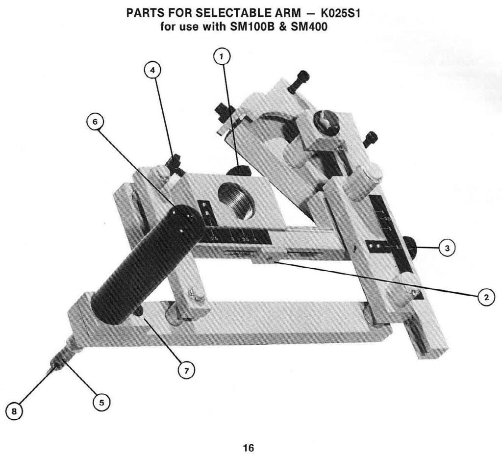
1 Instructions & Parts SM100B SM400 K025S1 K005 Table of Contents 2 SM100B/SM400 Manual Engraver Machine Diagram Pantograph Operation Setup & Layout Engraving & Changing Cutters Adjusting Depth of Cut & Continuous Engraving Name Tags & Font Letter Sizes Layout Design Tips Maintenance & Spare Parts 13 K025S1 Selectable Arm Installation & Operation Finished Font Sizes Adjustments 19 K005 Motor Instructions Since 1962 Scott Machine Development Corp. 200 Prospect Ave., Walton, NY Tel: 607/ :30-5:00 ET M-F Instructions-&-Parts-June2016
2

3
4
5

6

7

8

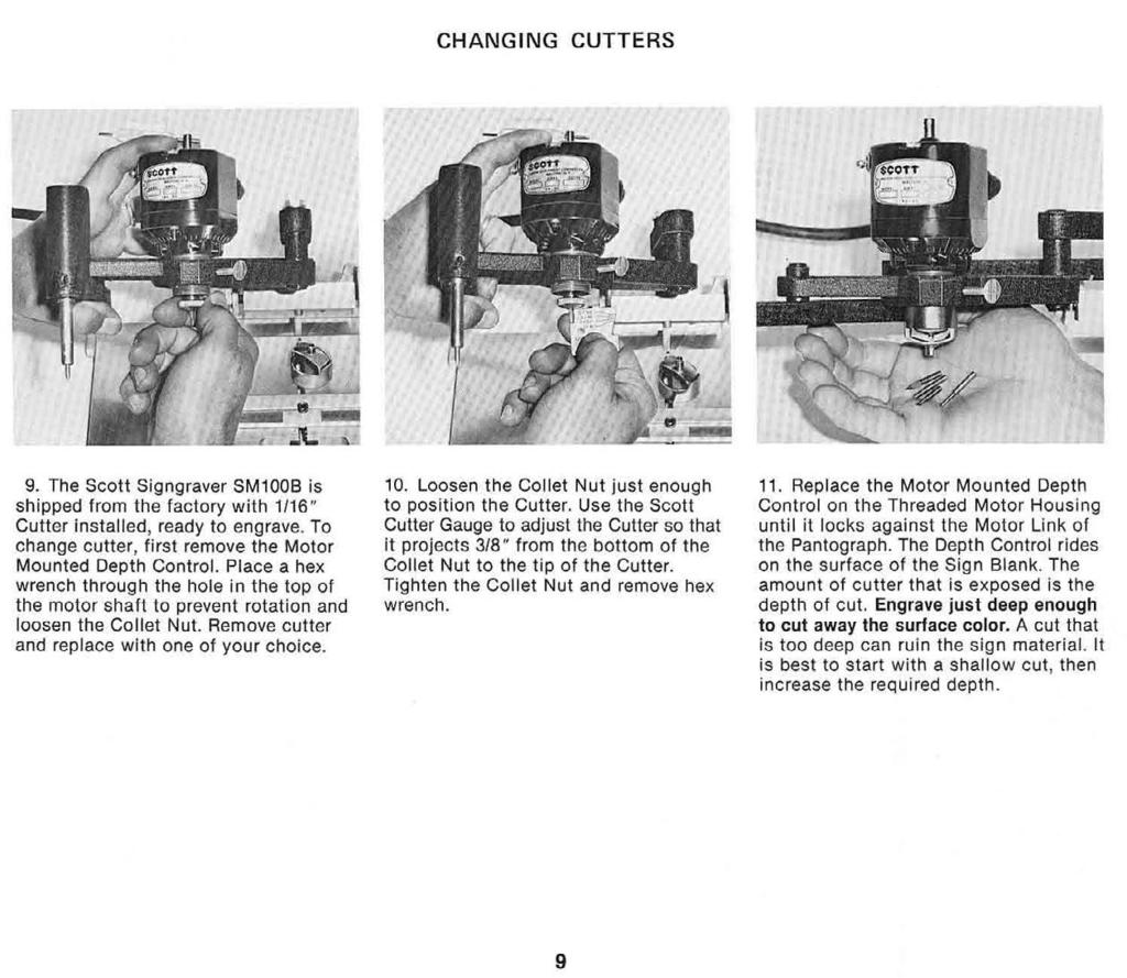
9
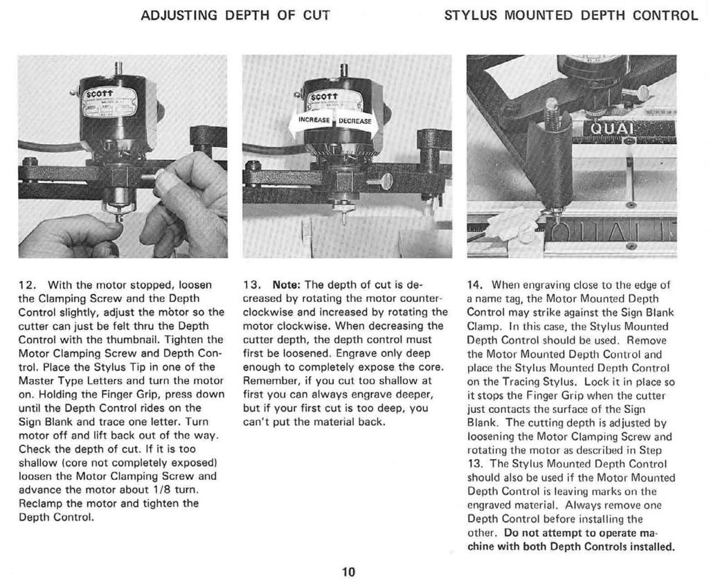
10
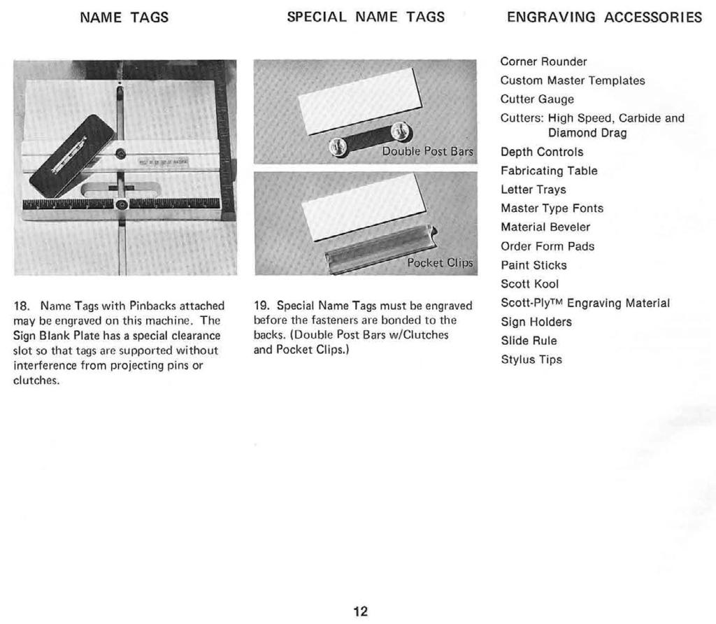
11
12
13 K025S1 - Selectable Arm for SM100B Installation & Operating Instructions Scott Machine Development Corp. Ship: 200 Prospect Ave. Mail: PO Box 88, Walton, NY Tel: Fax: Web:
14 K025S1 - Selectable Arm for use with SM100B & SM400 Spare Parts - List Price Minimum Order $25.00 CATALOG NO. DESCRIPTION PRICE KS001 Motor link lock screw assembly (washer) $ 6.60 KS002 T-slot nut KS003 Pivot link lock screw assembly (washer) 7.80 KS004 Motor thumb screw assembly (nylon plug) 3.10 KTSB1 Pantograph stylus holder K044 Pantograph grip cover - black 5.80 K045 Pantograph grip assembly K046 Set screw only for stylus shaft 1.60 Use with K005* (117 volt) motor (NOT INCLUDED). * K007 (Power Converter) for export.
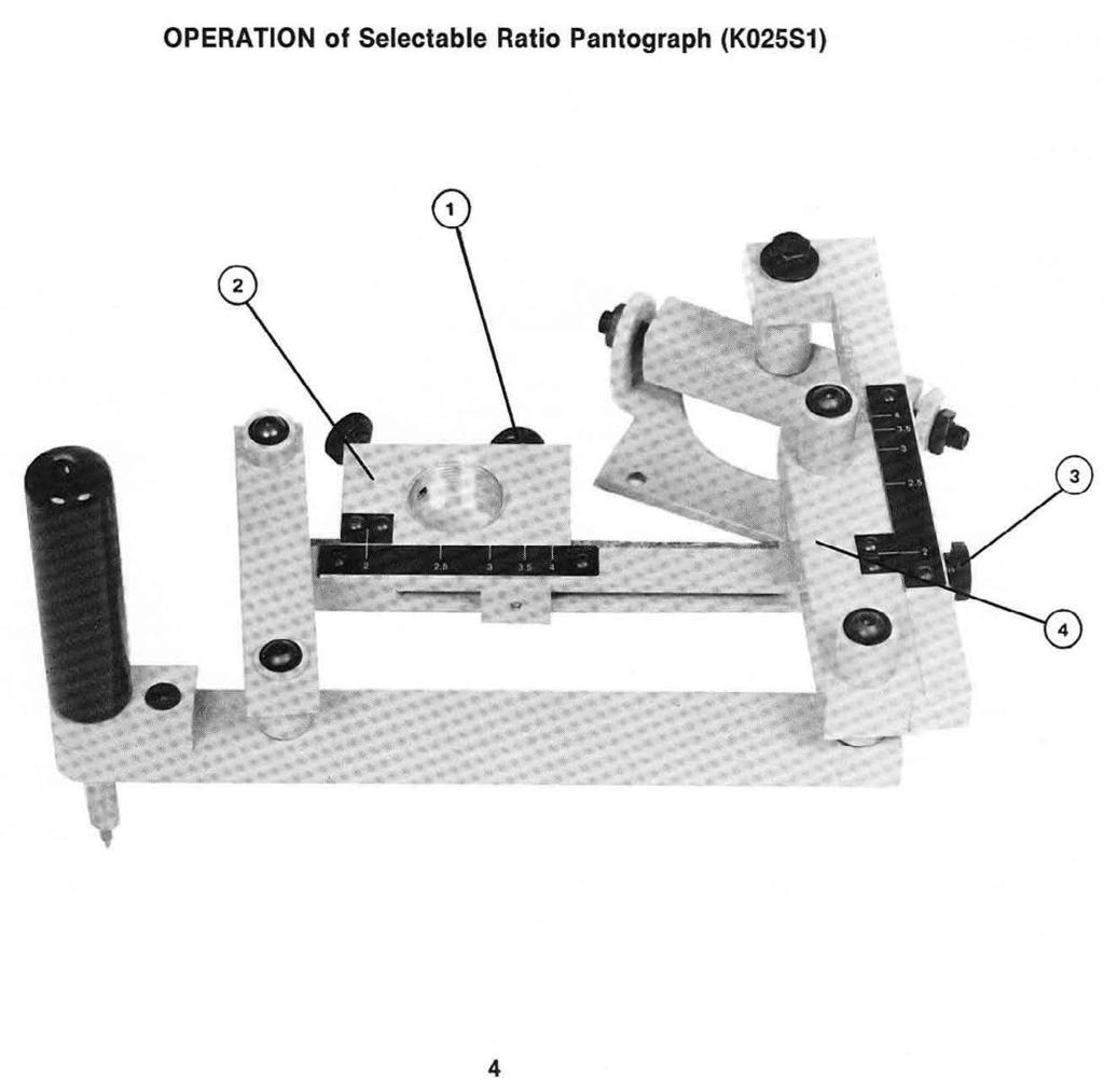
15 INSTALLATION of Selectable Arm (K025S1) and Pantograph Mounting Bracket (K026S1) onto SM100B Remove 2:1 mounting kit (K100B05) and mounting kit (K100B16) by removing two screws. Use spacer bar to mount selectable pantograph (K025S1) and mounting kit (K026S1). Tighten screws. OPERATION of Selectable Ratio Pantograph (K025S1) Loosen motor link lock screw. Slide motor mounting block to desired ratio, align marks and tighten screw.* Loosen pivot link lock screw. Slide pivot link to desired ratio, align marks and tighten screw.* Proceed with use of pantograph as outlined in Signgraver (SM100B or SM400) operating instructions. * Please Note: These marks must be properly aligned to ensure the best engraving. Special Note: With smaller fonts and greater reductions (eg. ML212, 4:1) use stylus mounted depth control (K002B). See pg 8, item 14 in SM100B/400 operating instructions.
16 FONT TEMPLATES Sizing Chart
17 ADJUSTMENTS to Machine when Changing Ratio and/or Fonts Please read before engraving: As each different ratio is selected on the pantograph, the actual span of the arm is increased or decreased in size. Therefore it is necessary to compensate by adjusting the machine to fit the ratio selected. Each Tag Engraver base has 3 locations (holes labelled A, B, C) for the upper Master Type Bar. Additionally, the Sign Blank Plate (or Tag Adapter) can be inserted into the machine in a reverse position. The following chart is to be used as a guideline so that the machine can be properly set up before engraving. Note: This chart illustrates set up allowing for maximum sign blank size that can be used in each ratio. * Tag Adapter in reverse position Font Ratio Upper master type bar hole location ML210 1/4 master ML211 3/8 master ML212 5/8 master ML13 1 master ML /16 master ML15 1 3/4 master Maximum sign blank size Sign blank plate or tag adapter position 2 A 3½ forward 2.5 A 3 * reverse 3 A 2 * reverse 3.5 A 1½ * reverse 4 not recommended 2 A 3½ forward 2.5 A 2½ * reverse 3 A 2 * reverse 3.5 C 1 * reverse 4 C ¾ * reverse 2 A 3½ forward 2.5 A 2½ * reverse 3 A 2 * reverse 3.5 C 1 * reverse 4 C ¾ * reverse 2 A 3½ forward 2.5 B 2¼ * reverse 3 B 2 * reverse 3.5 B 1¼ * reverse 4 B 1 * reverse 2 A 3½ forward 2.5 A 3 * reverse 3 A 2 * reverse 3.5 A 1½ * reverse 4 B 1 * reverse 2 A 3½ forward 2.5 A 3½ * reverse 3 A 2 * reverse 3.5 B 1½ * reverse 4 B 1¼ * reverse continued...
18 ADJUSTMENTS to Machine when Changing Ratio and/or Fonts Note: This chart illustrates set up allowing for maximum sign blank size that can be used in each ratio with large letters while allowing for a longer message with more characters. Font Ratio Upper master type bar hole location ML /16 master ML15 1 3/4 master Maximum sign blank size Sign blank plate or tag adapter position 2 A 3½ forward 2.5 B 2½ * reverse 3 B 2 * reverse 3.5 B 1¼ * reverse 4 C 1 * reverse 2 A 3½ forward 2.5 B 2½ * reverse 3 B 2 * reverse 3.5 C 1 * reverse 4 C 1 * reverse
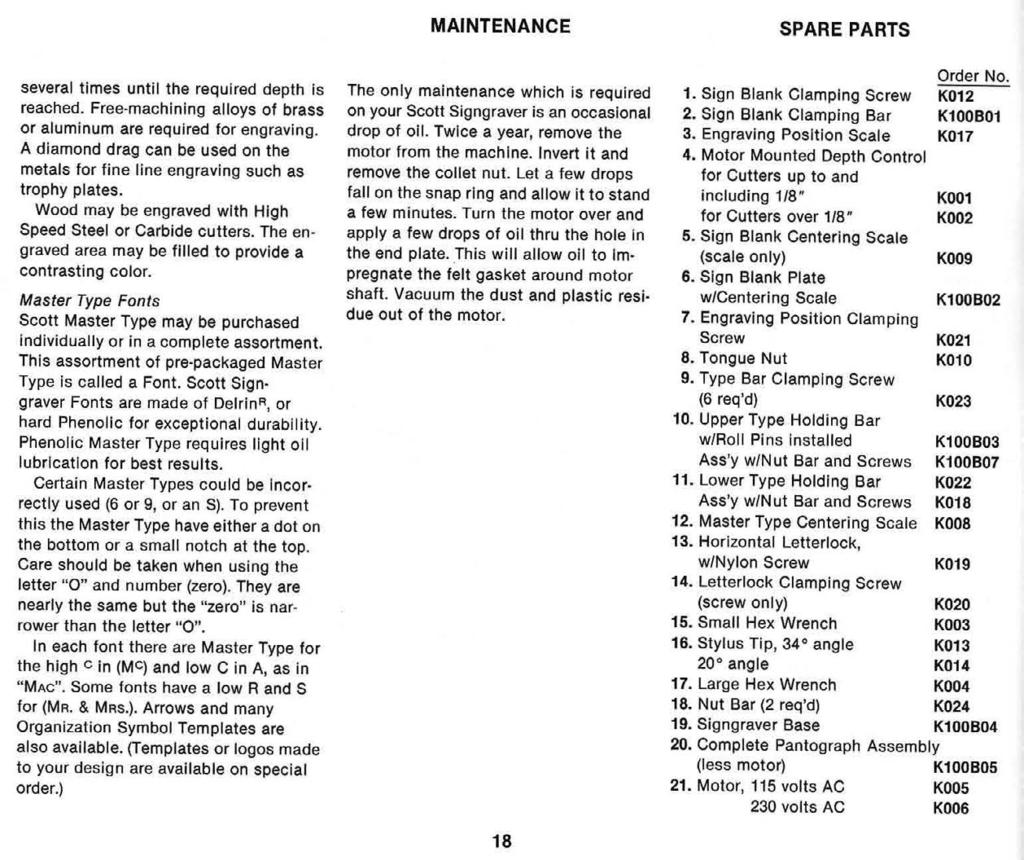
19 Scott Machine Development Corporation 200 Prospect Ave PO Box 88 Walton, NY Phone: Fax: K005 Engraver & Beveler Motor INSTALLING CUTTERS Always unplug Motor before changing cutter Remove Motor Mounted Depth Control Press the Shaft Lock Button and loosen the Collet Nut. Remove the cutter and replace with the one of your choice Tighten Collet Nut just enough so cutter can still move freely. Replace the Motor Mounted Depth Control on the motor until it locks against the Motor Link. The Cutter tip should be protruding from the Motor Mounted Depth Control. Press a flat piece of engraving material against the cutter tip so it is flush with the end of the Motor Mounted Depth Control. Press the Shaft Lock Button and tighten the Collet Nut. Loosen the Motor Clamping Screw and turn the motor clockwise 1/8 of a turn. Tighten the Motor Clamping Screw. Tighten the Motor Mounted Depth Control. The tip of the cutter should be exposed slightly. The amount it is exposed will be the depth of the cut. Always start with a shallow cut, then increase to the required depth. Motor Speed Switch; Set to LOW for Engraving Set to HIGH for Beveling Shaft Lock Button Motor Link MOTOR SPEED SWITCH Low - Use for Engraving High - Use for Beveling Motor Clamping Screw with Nylon Plug to protect motor threads Collet Nut Motor Mounted Depth Control Cutter
ABM International, Inc. Navigator Assembly Manual
 ABM International, Inc. 1 1.0: Parts List Tablet (Qty. 1) Tablet mount (Qty. 1) NOTE: Mount may appear and operate different then image below Control Box (Qty. 1) Motor Power Supply (Qty. 1) 2 X-axis motor
ABM International, Inc.
 ABM International, Inc. Lightning Stitch required 1 1.0: Parts List head and motor assembly (Qty. 1) Reel stand (Qty. 1) Needle bar frame clamp (Qty. 1) Motor drive (Qty. 1) 2 Cable harness with bracket
MEC Auto-Mate Assembly Manual. For MEC 9000G/GN and 8567 Grabber Series
 MEC Auto-Mate Assembly Manual For MEC 9000G/GN and 8567 Grabber Series Thank you We really appreciate your support of our product line. But our commitment to you hardly ends here. We won't be satisfied
MODEL 36 Di-Acro Hand Shear
 OPERATOR S MANUAL & INSTRUCTIONS MODEL 36 Di-Acro Hand Shear Di-Acro, Incorporated PO Box 9700 Canton, Ohio 44711 3713 Progress Street N.E. Canton, Ohio 44705 330-455-1942 330-455-0220 (fax) Revised 01/02
Projector Flush Mount
 Projector Flush Mount ABtUS SIGAPORE PTE LTD Model: AV819 www.abtussingapore.com Patent Pending Revision 21/05/2012 ABtUS SINGAPORE PTE LTD www.abtussingapore.com User Operation Guide IMPORTANT NOTES Thank
KIT. Assembly Instructions. HayDay, LLC
 KIT Assembly Instructions HayDay, LLC 1-800-732-1654 www.stablegrazer.com Read completely through the assembly instructions before starting assembly. The Stable Grazer Kit comes in two boxes. Remove all
SALICE AIR TEMPLATE KIT
 SALICE AIR TEMPLATE KIT There are two separate templates available for the machining of the AIR hinge; one is used for machining both the top and bottom of the door while the other is used for machining
Copyright 2007 MLCS 1
 Copyright 2007 MLCS 1 REFERENCE GUIDE and SPECIFICATIONS: Edge Guides: This 12 Dovetail Template comes complete with 2 Edge Guide Sets one set for Half Blind and one set for Rabbeted Half Blind Dovetails.
M2 Assembly. M2 Sub-Assemblies mm Belt Sub-Assembly mm Belt Sub-Assembly Spider Sub-Assembly... 4
 M2 Assembly Table of Contents M2 Sub-Assemblies... 3 630mm Belt Sub-Assembly... 3 702mm Belt Sub-Assembly... 3 Spider Sub-Assembly... 4 Idler Bolt Sub-Assembly... 8 Y Motor Sub-Assembly... 9 X Motor Sub-Assembly...
EPPA2-KIT DUAL MONITOR ARM CONVERSION
 EPPA2-KIT DUAL MONITOR ARM CONVERSION EPPA2-KIT Rev A 10/17 Model EPPA2-KIT-XXX ASSEMBLY AND ADJUSTMENT EPPA2-KIT PARTS AND TOOLS PLEASE REVIEW these instructions before beginning the assembly and adjustment
GlideRite Retractable Cover System For Hot Spot Spas (SE & SLX only)
") List of Contents Quantity Description 12 #10 x 1 ½ Flat Head Phillips Screw (see pg. 2) 2 #10 x ½ Pan Head Phillips Screw (see pg. 2) 8 ¼ x 2 ½ Lag Bolt (see pg. 2) 7 ¼ 20 x 5 / 8 Hex Head Bolt (see pg.
List of Contents Quantity Description 12 #10 x 1 ½ Flat Head Phillips Screw (see pg. 2) 2 #10 x ½ Pan Head Phillips Screw (see pg. 2) 8 ¼ x 2 ½ Lag Bolt (see pg. 2) 7 ¼ 20 x 5 / 8 Hex Head Bolt (see pg.
D3976 RECESSED EXIT INSTALLATION INSTRUCTIONS
 PACKAGE CONTENTS PRODUCT MUST BE INSTALLED ACCORDING TO ALL APPLICABLE BUILDING AND LIFE SAFETY CODES TEMPLATE INSTALLATION INSTRUCTIONS STRIKE HAND TOOL 5/32 HEX KEY ROD END CAPS EXIT DEVICE CRANK ARM
GlideRite Retractable Cover System For HotSpring & Tiger River Spas (except Classic & pre-2000 Landmark Spas)
") List of Contents Quantity Description 12 #10 x 1 ½ Flat Head Phillips Screw (see pg. 2) 2 #10 x ½ Pan Head Phillips Screw (see pg. 2) 8 ¼ x 2 ½ Lag Bolt (see pg. 2) 7 ¼ 20 x 5 / 8 Hex Head Bolt (see pg.
List of Contents Quantity Description 12 #10 x 1 ½ Flat Head Phillips Screw (see pg. 2) 2 #10 x ½ Pan Head Phillips Screw (see pg. 2) 8 ¼ x 2 ½ Lag Bolt (see pg. 2) 7 ¼ 20 x 5 / 8 Hex Head Bolt (see pg.
LF Series Assembly Instructions
 LF Series Assembly Instructions 1998760 Revision A-10 Complete Series Master Packet 2010 Kimball International, Inc. T 800.482.1818 F 812.482.8300 Footprint Storage and Metal Filing Systems Assembly Instructions
Depending on the size you ordered you will have either 5 Foot sections which will build the 10 Foot frame or 6 Foot sections which will build the 12
 XL Quilting Frame 1 Depending on the size you ordered you will have either 5 Foot sections which will build the 10 Foot frame or 6 Foot sections which will build the 12 Foot frame Printed 2 June 2014 Updated
HQ Pole Upgrade Kit for HQ Adjustable Table and HQ QuilTable Assembly Instructions 1
 HQ Pole Upgrade Kit for HQ Adjustable Table and HQ QuilTable Assembly Instructions QF09775 The pole upgrade kit can be used with or without the QF09700 HQ Precison-Glide track upgrade kit. What s Included
Replacing the Reciprocator on the SWF Compact Series Machine (601C and 1201C)
") Follow the instructions below to replace the reciprocator in the SWF Compact series machines. The tools required can be found in the tool kit that came with the machine. Preparation 1. First, place the
Follow the instructions below to replace the reciprocator in the SWF Compact series machines. The tools required can be found in the tool kit that came with the machine. Preparation 1. First, place the
V-Groover SIMPLEX INSTRUCTION AND OPERATION MANUAL M O DEL 703. For best results use only authentic Logan blades.
 www.logangraphic.com SIMPLEX M O DEL 703 INSTRUCTION AND OPERATION MANUAL For best results use only authentic Logan blades CAUTION: BLADES EXTREMELY SHARP Use replacement blades #1258 Logan Graphic Products,
JD-12. Instruction & Parts Manual
 JD-12 Instruction & Parts Manual Framon Manufacturing Company, Inc. 909 W Washington Avenue Alpena, MI 49707 Phone: 989-354-5623 Fax: 989-354-4238 E-mail: support@framon.com Website: www.framon.com The
EZ-Lock Assembly Manual
 ABM International, Inc. EZ-Lock Assembly Manual 1 ABM International, Inc. Series: 1018/1022/1026 V1.0 EZ-Lock Parts List - Structural frame profiles Slotted beam: (Qty. 2) 15.75 Commercial Parts - Liner
Giraud Tool Company, Inc.
 Motor Upgrade for Gracey Trimmer This package is intended to allow the user to upgrade their Gracey trimmer with a higher rpm motor and convenience features not found in the production offering. This upgrade
Installation Instruction
 Tools Needed for Assembly Stud finder (for wood stud wall) Pencil Mark Electric drill Wood Stud Wall Installation Step 1. Locate the Wood Studs Installation Instruction Drill bit (for wood stud wall) Masonry
OWNER S MANUAL. Safety. Please read this owner s manual before use and keep it at hand for reference. Warranty
 Please read this owner s manual before use and keep it at hand for reference. OWNER S MANUAL Safety Important safety instructions for using the INCRA Miter5000 Before using the INCRA Miter5000, read and
Q-Zone Hoop-Frame. Assembly Instructions. Copyright July 11, 2018 Grace Company (Reproduction Prohibited) Version 1.8
 Version 1.8") Q-Zone Hoop-Frame Assembly Instructions Copyright July 11, 2018 Grace Company (Reproduction Prohibited) Version 1.8 Table of Contents Table of Contents... i Warranty... ii Parts List Box 1...iii Box 2...
Q-Zone Hoop-Frame Assembly Instructions Copyright July 11, 2018 Grace Company (Reproduction Prohibited) Version 1.8 Table of Contents Table of Contents... i Warranty... ii Parts List Box 1...iii Box 2...
PFW 6851 Display Wall Mount, Turn & Tilt 80 kg INSTALLATION INSTRUCTIONS
 Display Wall Mount, Turn & Tilt 80 kg INSTALLATION INSTRUCTIONS 9531-007-Z00-01 Table of Contents Warning Statements 2 Parts List 3 Installation Tools 3 Wood Stud Installation 5 Concrete Surface Installation
ELECRAFT KXPD1 PLUG-IN KEYER PADDLE
 Introduction ELECRAFT KXPD1 PLUG-IN KEYER PADDLE Assembly and Operating Instructions Revision B, July 27, 2011. Copyright 2011, Elecraft; All Rights Reserved The KXPD1 is a unique plug-in keyer paddle
 Operating Instructions Table of Contents Page Operating Instructions 2-3 Changing Character Dial Instructions 4 3/16 Line and Letter Charts 5 Assembly Drawings 6-7 Repair Parts List 8 Trouble Shooting
RBP-1215B-RX DODGE RAM QUAD CAB RX3
 RBP-1215B-RX3 2002-2017 DODGE RAM 15-3500 QUAD CAB RX3 Passenger side RX-3 Side Step Drill Template Passenger side rear Modular Bracket (6) L Support Brackets Driver side rear Modular Bracket Driver side
This manual will aid in the assembly of the FireBall V90 and FireBall X90. The assembly of both machines will be identical, unless specified.
 This manual will aid in the assembly of the FireBall V90 and FireBall X90. The assembly of both machines will be identical, unless specified. Step #1 Lay all parts out to verify quantities. (2) 2 x 25-1/4
F l a t S c r e e n A R M S I n s t a l l a t i o n
 ITEM NUMBERS (1) #TOACAORG16 (2) #TOACAORG20 (3) #TOACATRP24 (4) #TOACATRP30 (5) #TOACATRPDS (6) #TOACATRPSS TOOLS REQUIRED (1) 3/8 Wrench (not provided) (2) Phillips head screwdriver (not provided) (1)
AndyMark DART 12.
 AndyMark DART 12 Part Number Description QTY These Parts Are Pre-Assembled by AndyMark am-0031 Bearing, 3/16"ID (R3) 1 am-0209 Bearing, 3/8"ID 1614ZZ 2 am-1028 Screw, #10-32x3/8 Pan Head Philips 8 am-1121
OPERATION AND MAINTENANCE HANDBOOK D407270XA
 OPERATION AND MAINTENANCE HANDBOOK D407270XA vers. 1.0 Thank you for choosing one of Silca s high quality key cutting machines. This machine has been designed, tested and produced in our factory using
Star Trac Turbo Trainer Assembly & Setup
 Star Trac Turbo Trainer Use the following procedures to unpack and assemble your Turbo Trainer manufactured by Star Trac. UNPACKING AND PARTS LIST Position the shipping carton so the Heavy End logo is
Arc Trainer Main Frame Assembly
 Arc Trainer Main Frame Assembly Kit No. 610AK019-4 Kit No. 630AK019-4 NOTE: This instruction sheet describes how to replace the main frame assembly in the Arc Trainer 610A. Tools Required 3/16 Allen wrench
TOYOTA MOTOR EUROPE CA Products Division Tel : Fax :
 TOYOTA MOTOR EUROPE CA Products Division Tel : + 32 2 745 26 77 Fax : + 33 2 745 26 99 Ordering part numbers Comments Part Numbers Wooden floor one hatch PZ449-D3C42-11 one hatch with carpet PZ449-D3C42-01
INSTALLATION MANUAL. All Recessed Wall-Mount Modules Front-Loading, Rear-Loading, Parcel-Only, Collection Box, Trash/Recycling Bin
 INSTALLATION MANUAL All Recessed Wall-Mount Modules Front-Loading, Rear-Loading, Parcel-Only, Collection Box, Trash/Recycling Bin TABLE OF CONTENTS GENERAL INFORMATION AND ADVISORIES 3 USPS INSTALLATION
8.0 RE-CALIBRATION OF SPACE
 8.0 RE-CALIBRATION OF SPACE 101 ATTENTION: PLEASE READ BEFORE PROCEEDING. RE-CALIBRATION OF SPACE NO RE-ADJUSTMENT of space is required when changing from one code card to another. The space indicator
(2) Plastic Plugs (2) Frame Bracket. Spacers. License Plate Bracket. (2) 12mm Single Bolt Plates. (2) 12mm Double Bolt Plates
 Plastic Plugs (2) Frame Bracket. Spacers. License Plate Bracket. (2) 12mm Single Bolt Plates. (2) 12mm Double Bolt Plates") LDB-CSIL26-FB PARTS LIST: 1 LD1 Bumper Assembly 10 12mm Hex Nuts 1 Driver/left Frame Mounting 6 10-1.5mm x 35mm Hex Bolts 1 Passenger/right Frame Mounting 12 10mm x 27mm OD x 3mm Flat Washers 2 Spacers
LDB-CSIL26-FB PARTS LIST: 1 LD1 Bumper Assembly 10 12mm Hex Nuts 1 Driver/left Frame Mounting 6 10-1.5mm x 35mm Hex Bolts 1 Passenger/right Frame Mounting 12 10mm x 27mm OD x 3mm Flat Washers 2 Spacers
Ringblaster Mark IV Maintenance Guide. Version 1.5
 Ringblaster Mark IV Maintenance Guide Version 1.5 WARNING Winchester Industrial Equipment and Loads must be properly stored, handled and maintained for safe and proper function. Mishandling or failure
APS Small Seeds Box Assembly Instructions
 APS Small Seeds Box Assembly Instructions For APS15 Series All Purpose Seeder Manual No. 313-473M Before You Start! When you see this symbol, the subsequent instructions and warnings are serious - follow
METAL BENDER OPERATING & MAINTENANCE INSTRUCTIONS Model Nos: CCB1 & CCB2 Part Nos: & CCB2 CCB1
 METAL BENDER Model Nos: CCB1 & CCB2 Part Nos: 7630073 & 7630074 CCB2 CCB1 OPERATING & MAINTENANCE INSTRUCTIONS 1206 1 The Compact Bender allows you to economically make a variety of bends in flat, square,
Universal Barricade Assembly Instructions
 Universal Barricade Assembly Instructions (Part # 3000668-M) Table of Contents I. Introduction 2 II. Placement of the Universal Center Pivot Barricade 2 III. Component Identification 3 IV. Assembly 4 Page
INSTALLATION INSTRUCTIONS Flat Panel Static Wall Mount Model: GSM-111
 INSTALLATION INSTRUCTIONS Flat Panel Static Wall Mount Model: GSM-111 The GSM-111 static wall mount fits most 23" to 30" displays. The GSM-111 is designed to adapt to VESA 200mm/ 100mm compliant displays.
INSTALLATION INSTRUCTIONS Small Flat Panel FMA Pivot Arrays Models: FMA-220 and FMA-320
 INSTALLATION INSTRUCTIONS Small Flat Panel FMA Pivot Arrays The FMA-220 and FMA-320 pivot array allow both horizontal and vertical display pitch adjustment. The pitch adjustment range is 30 (15 up / 15
APES HD-7700 Version Operator s Training Manual
 APES-14-77 HD-7700 Version Operator s Training Manual Issue A1 09/03 P/N 900599 Performance Design Inc. 2350 East Braniff St. Boise Idaho 83716 This manual contains very important safety information and
INSTALLATION INSTRUCTIONS
 INSTALLATION INSTRUCTIONS PARTS REQUIRED Single QuickStand Lite Parts A (1) Lower Arm A B C D B (1) Upper Arm C (1) Base D (1) Base Plate E (1) M8 Dynamic Arm Long F (1) Clamp Bracket G H (1) VESA Plate
33/3547A. Special tools needed: #10-24 tap Drill bits: #25, 5/16, 13/32, 1/2
 911404-00 Concealed Vertical Rod Exit Device 33/3547A Installation Instructions Devices covered by these instructions: 33/3547A and 33/3548A Concealed Vertical Rod Exit Device 33/3547A-F and 33/3548A-F
OPERATOR'S MANUAL ROUTER MOUNTING KIT
 OPERATOR'S MANUAL MOUNTING KIT 4950301 (FOR USE WITH BT3000 AND BT3100 TABLE SAWS) Your new router mounting kit has been engineered and manufactured to Ryobi's high standard for dependability, ease of
Legacy Woodworking Machinery a division of Phantom Engineering. The Legacy CNC. Assembly Manual
 Legacy Woodworking Machinery a division of Phantom Engineering The Legacy CNC Assembly Manual New Orientation of the Legacy Step one: Re-orientation of the machine Remove the X-axis screw and supports.
REQUIRED EQUIPMENT SETUP
 #003-598 raverhone VS OPERATION AND MAINTENANCE MANUAL 24V IMPORTANT NOTICE FOR OPERATORS No user serviceable parts inside. Do not remove any outer surfaces. Do not modify this equipment or remove warning
ASSEMBLY AND ADJUSTMENT
 EPPA MONITOR ARM EPPA Rev A 10/17 Model EPPA-XXX ASSEMBLY AND ADJUSTMENT EPPA MONITOR ARM PARTS AND TOOLS PLEASE REVIEW these instructions before beginning the assembly and adjustment procedures. Check
Basic steps to time the Gammill quilting machine s rotary sewing hook
 Basic steps to time the Gammill quilting machine s rotary sewing hook 1.) Turn the machine off and unplug it. 2.) With the needle bar in the raised position, remove the bobbin and bobbin case. 3.) Remove
-Eagle Edger Jr Linear Edge Add-on for the Blue Ripper Jr
 -Eagle Edger Jr Linear Edge Add-on for the Blue Ripper Jr (Blade shown might not ship with tool, or be available.) Operation, Safety, and Instruction Manual v20150521 Page 2 Operating/Safety Instructions
Quill Stop V2 Installation Guide 11/16/2014
 Thank you for purchasing the Quill Stop for the Sieg X3 (Grizzly G0463) and SX3 (Grizzly G0619) mills. Your feedback is always appreciated. Please email questions and comments to gregpriest@cox.net. What
SERIES I MILLING MACHINES
 INSTALLATION, OPERATION, MAINTENANCE, AND PARTS LIST SERIES I MILLING MACHINES TP5260 Revised: August 29, 2005 Manual No. M-450 Litho in U.S.A. Part No. M -0009500-0450 June, 2003 MAINTENANCE PROCEDURES
Installation instructions for FC14S Forward Controls for Shadow ACE and Aero 1100
 Installation instructions for FC14S Forward Controls for Shadow ACE and Aero 1100 It is highly recommended that you use a thread lock compound such as Loctite brand on all threads to keep them from vibrating
Installation and Assembly - Universal Articulating Swivel Double-Arm for 42" - 60" Plasma Screens
 Installation and Assembly - Universal Articulating Swivel Double-Arm for 42" - 60" Plasma Screens Models: PLAV 70-UNL, PLAV 70-UNL-S PLAV 70-UNLP, PLAV 70-UNLP-S R This product is UL Listed. It must be
LCD TV WALL MOUNT INSTALLATION INSTRUCTIONS. DUAL Swing Arm (RFWD-110) WARNING
 WARNING") INSTALLATION INSTRUCTIONS LCD TV WALL MOUNT DUAL Swing Arm (RFWD-110) WARNINGS WARNING WARNING CAUTION CAUTION The maximum weight to be installed on the RFWD wall mount is 40 lbs. (18.1 kg). The RFWD is
INSTALLATION INSTRUCTIONS LCD TV WALL MOUNT DUAL Swing Arm (RFWD-110) WARNINGS WARNING WARNING CAUTION CAUTION The maximum weight to be installed on the RFWD wall mount is 40 lbs. (18.1 kg). The RFWD is
HEAVY DUTY GASKET CUTTER
 HEAVY DUTY GASKET CUTTER GUIDE TO PERFECT GASKETS CUTTING GASKETS 1 TO 13 IN DIAMETER: 1. Lay out gasket outer diameter (OD), inner diameter (ID) and bolt holes on template or gasket material. See section
Droplit v2 Frame Assembly
 SeeMeCNC Guides Droplit v2 Frame Assembly Droplit v2 Frame Assembly Written By: JJ Johnson 2017 seemecnc.dozuki.com Page 1 of 22 Step 1 Droplit v2 Frame Assembly Locate the Projector Plate, Projector Joining
SmartView Mounting Frame 3 Wide x 3 Deep Video Wall Display Installation Guide
 SmartView Mounting Frame 3 Wide x 3 Deep Video Wall Display Installation Guide WMK-034 This display kit mounts ViewSonic 46 Video Wall displays in a 3 wide by 3 deep landscape configuration. The frame
RIPPER PEDAL. Bearing / Axle Replacement. ( Disassembly )
") RIPPER PEDAL Bearing / Axle Replacement ( Disassembly ) 1 1. Use good quality tools to avoid stripping screw sockets. 2. When servicing your pedals, work on one side at a time to prevent parts from mixing
RIPPER PEDAL Bearing / Axle Replacement ( Disassembly ) 1 1. Use good quality tools to avoid stripping screw sockets. 2. When servicing your pedals, work on one side at a time to prevent parts from mixing
HAND SHEARS NO. 12 AND NO. 24
 OPERATOR S MANUAL & INSTRUCTIONS HAND SHEARS NO. AND NO. Di-Acro, Incorporated PO Box 9700 Canton, Ohio 7 7 Progress Street N.E. Canton, Ohio 70 0--9 0--00 (fax) Revised 0/0 Sale or distribution of manuals
Code Product Qty 1 Top Vertex 3 2 Hot End Housing 1 3 Bottom Vertex 3 4 Print Platform Lock 3 5 End Stop Holder 3 6 Filament Feeder Motor Bracket 1 7
 List of Parts Code Product Qty 1 680mm Extrusion 3 2 Power Supply 1 3 240mm Extrusion 9 4 42mm Nema 17 Stepper Motor 3 5 Slider-Hotend Connecting Rod 6 6 48mm Nema 17 Stepper Motor 1 7 Linear Rail with
USER MANUAL & PARTS LIST MODEL 40B S/N:
 NUMBERALL STAMP & TOOL CO., INC. USER MANUAL & PARTS LIST MODEL 40B S/N: P.O. BOX 187, 1 HIGH ST. SANGERVILLE, ME 04479 www.numberall.com office@numberall.com TEL: 207-876-3541 FAX: 207-876-3566 MODEL
Hatch Whiteboard: Portable Stand Installation Instructions
 Hatch Whiteboard: Portable Stand Installation Instructions Remove Projector Wall Plate 1. Open the wall mount for the projector. 2. Remove the shipping screw from the front center of the mount arm. 1 P
MORTISE LOCK INSTALLATION INSTRUCTIONS
 MORTISE LOCK INSTALLATION INSTRUCTIONS INSPIRE TM ROSELESS DESIGNER TRIM FM 340 Rev. 10/18 TABLE OF CONTENTS: DOOR PREPARATION 1 ML2000 LOCK HANDING 2 FULL WORKING TRIM (STD) 3 HALF WORKING TRIM (M30)
N. 15th Street, Middlesboro, KY FLIP TARP DUMP BODY INSTALLATION INSTRUCTIONS
 1-800-248-7717 1002 N. 15th Street, Middlesboro, KY 40965 FLIP TARP DUMP BODY INSTALLATION INSTRUCTIONS Congratulations on your purchase of a Mountain Flip Tarp Dump Body tarping system. With tarping systems
Owner s Manual AE PLUG AERATOR MANUFACTURING QUALITY LAWN CARE EQUIPMENT SINCE Made In CHINA REV
 MANUFACTURING QUALITY LAWN CARE EQUIPMENT SINCE 1945 Owner s Manual AE-48 48 PLUG AERATOR IMPORTANT Read and follow all Safety Precautions and Instructions Before Operating this Equipment. Made In CHINA
Installation and Assembly - Universal Articulating Swivel Double-Arm for 42" - 60" Plasma Screens
 Installation and Assembly - Universal Articulating Swivel Double-Arm for 42" - 60" Plasma Screens Models: PLAV 70-UNL, PLAV 70-UNL-S PLAV 70-UNLP, PLAV 70-UNLP-S R This product is UL Listed. It must be
SERVICE PARTS LIST PAGE 1 OF 6 BASE ASSEMBLY SPECIFY CATALOG NO. AND SERIAL NO. WHEN ORDERING PARTS 12" SLIDING COMPOUND MITER SAW
 PAGE 1 OF 6 BASE ASSEMBLY 00 0 CATALOG NO. EXAMPLE: SPECIFY CATALOG NO. AND NO. WHEN ORDERING PARTS 6955-20 1 02-80-0050 Thrust Bearing (1) 2 05-80-0510 M5 x 12mm Flat Head T-20 Screw (5) 3 05-81-0135
STRINGING MACHINE OWNER'S MANUAL. Copyright 1998 GAMMA Sports - All Rights Reserved
 6002 STRINGING MACHINE OWNER'S MANUAL Issue 3 - June 20, 1998 Copyright 1998 GAMMA Sports - All Rights Reserved 6002 OWNER'S MANUAL TABLE OF CONTENTS PAGE 1... WARRANTY PAGE 2... FEATURES PAGE 3... ASSEMBLY
Please read BOTH these Installation Instructions and the General Instructions prior to installing or operating this equipment.
 Attachment Tab Height: 13 Attachment Tab Width: 24 Please read BOTH these and the General Instructions prior to installing or operating this equipment. Serial Number 1. Blue Ox towing products and accessories
Customer Notice: Congratulations again on your SawStop purchase, and thank you! -SawStop Tualatin, OR
 Customer Notice: Congratulations on the purchase of this Sliding Crosscut Attachment. As the owner of a SawStop saw, you are familiar with our high standards for quality, fit and finish. Different from
Installation Guide. Mounting Kit for Mounting Philips Avalon CTS Cordless Fetal Transducer System on Wall, 2'' Post, Rail, or Slide-on Mounting Plate
 Installation Guide Mounting Kit for Mounting Philips Avalon CTS Cordless Fetal Transducer System on Wall, 2'' Post, Rail, or Slide-on Mounting Plate The purpose of this guide is to: 1. Describe mounting
Pole Mount Installation Guide
 Pole Mount Installation Guide (No Fine Adjustment) 495R Billerica Ave. North Billerica, MA 01862 USA Tel (978)459-8800 fax (978)459-3310 / 8814 Email: sales@radiowaves.com www.radiowaves.com IMPORTANT!
INSTALLATION INSTRUCTIONS Small Flat Panel Mounts Model: F-Series
 INSTALLATION INSTRUCTIONS Small Flat Panel Mounts Model: F-Series This Instruction Manual covers most of the F-Series wall and desk mounts, as well as selected F-Series pole mounts. NOTE: Some F-Series
Wind Turbine Experimenter s Kit User Guide
 Wind Turbine Experimenter s Kit User Guide 42284 V0116 Cautionary and Warning Statements This kit is designed and intended for educational purposes only. Use only under the direct supervision of an adult
The Bowflex Revolution XP Home Gym Assembly Instructions. P/N: Rev ( /0 )
") P/N: 001-7057 Rev ( /0 ) The Bowflex Revolution XP Home Gym Assembly Instructions 2 Table of Contents Before You Start... 2 Tools You Will Need / Hardware Contents... 3 Box Contents... 6 Assembling Your
P/N: 001-7057 Rev ( /0 ) The Bowflex Revolution XP Home Gym Assembly Instructions 2 Table of Contents Before You Start... 2 Tools You Will Need / Hardware Contents... 3 Box Contents... 6 Assembling Your
Installation Instructions. Installation Type
 Installation Instructions 800 & 8050 Slide Track Door Closers Non Hold Open & Hold Open Models Note: Hold open models are not permitted to be installed in Listed fire door assemblies. PULL SIDE MOUNTED
INSTALLATION INSTRUCTIONS Horizontal And Vertical Table Stands and Accessories Model: KTP-Series
 INSTALLATION INSTRUCTIONS Horizontal And Vertical Table Stands and Accessories Model: KTP-Series The KTP-Series is a free standing, pole mount solution for multiple displays. KTP-320 KTP-220 / KTP-225
Formulate Accent Ladder 10
 Formulate Accent Ladder 10 FMLT-WL10 Formulate Master Accents enhance the functionality of many Formulate Master 10 and 20 backwalls and add more real estate for messaging too! With monitor supports, literature
S OLAR RADIATION S HIELD MANUAL
 S OLAR RADIATION S HIELD MANUAL This instruction manual is designed to take you step-by-step through the process required to assemble and mount your Solar Radiation Shield. Please take the time to read
Installation Instructions. Installation Type
 Installation Instructions 300 & 3050 Slide Track Door Closers Non Hold Open & Hold Open Models Note: Hold open models are not permitted to be installed in Listed fire door assemblies. PULL SIDE MOUNTED
model tsa-sa48 Sliding Crosscut Table installation guide
 model tsa-sa48 Sliding Crosscut Table installation guide A Note About Color Variations Among Anodized Aluminum Components Congratulations on the purchase of this SawStop Sliding Crosscut Table. We at SawStop
BX2173 Installation Instructions Ford Focus (including the 2.3L engine) 2003 Ford Focus SVT
 2003 Ford Focus SVT") BX2173 Installation Instructions 2000-04 Ford Focus (including the 2.3L engine) 2003 Ford Focus SVT Serial No. The front fascia, coolant line bracket and anti-pollution devices are removed for baseplate
BX2173 Installation Instructions 2000-04 Ford Focus (including the 2.3L engine) 2003 Ford Focus SVT Serial No. The front fascia, coolant line bracket and anti-pollution devices are removed for baseplate
MPA-9000 Universal Ceiling Projector Mount Kit
 I N S T R U C T I O N M A N U A L Universal Ceiling Projector Mount Kit The Universal Ceiling Projector Mount provides a unique, simplified method of ceiling mounting your inverted projector. This low
Quick Start Guide. Contents
 1 Quick Start Guide Contents Powering on the Machine Login/Password Entry Jaw Set Up High Security Cut by Code High Security Jaw Set Up Edge Cut Cut by Code Edge Cut Cut by Decode Cutter Replacement Tracer
HQ Precision-Glide Track Upgrade 2 Extension Kit for HQ Studio Frame Part# QF09750
 HQ Precision-Glide Track Upgrade 2 Extension Kit for HQ Studio Frame Part# QF09750 Important Note: Upgrading the track system on the HQ Studio Frame requires the use of this 2 Extension Kit (Part #QF09750),
INSTRUCTIONS AND PARTS LIST POWER HAMMER
 INSTRUCTIONS AND PARTS LIST POWER HAMMER DAKE (Division of JSJ) 724 Robbins Road Grand Haven, Michigan 49417 616.842.7110 Phone 800-937-3253 616.842.0859 Fax 800-846-3253 Web: www.dakecorp.com E-mail :
CV1B Sliding Table Installation and Setup Guide
 CV1B Sliding Table Installation and Setup Guide Tech Mark, Inc 7901 Industry Drive North Little Rock, AR 72117 tel (501) 945-9393 fax (501) 945-0312 www.tech-mark.com email: info@tech-mark.com The CV1B
Fig. 2 DORMA-Glas Stand/Issue 02/03 Seite/Page 1/7
 FSW Installation instructions Track rail 75 x 72 mm 1. Ceiling substructure and installation of the track rail (Fig. 1): The track rail must be bolted over its entire length (including the stacking track
Side Winder R o u t e r L i f t.
 Woodpeckers PRECISION WOODWORKING TOOLS Side Winder R o u t e r L i f t. INSTALLATION INSTRUCTIONS The wrench handle must be pointing left in order to fully insert or remove it. Lift Wrench Once fully
MODEL 83 Pail Handler
 MORSE MFG. CO., INC. 727 West Manlius Street P.O. Box 518 East Syracuse, NY 13057-0518 Phone: 315-437-8475 Fax: 315-437-1029 Email: service@morsemfgco.com Website: www.morsemfgco.com COPYRIGHT 2005 MORSE
1) Place the reactor stand on a sturdy bench with the bottom plate facing toward the front.
 Place the reactor stand on a sturdy bench with the bottom plate facing toward the front.") Assembly Instructions for ChemRxnHub Reactor Systems 1) Place the reactor stand on a sturdy bench with the bottom plate facing toward the front. Loosen knobs on the right and left using 2 hands of the
Assembly Instructions for ChemRxnHub Reactor Systems 1) Place the reactor stand on a sturdy bench with the bottom plate facing toward the front. Loosen knobs on the right and left using 2 hands of the
SERVICE PARTS LIST PAGE 1 OF 6 BASE ASSEMBLY SPECIFY CATALOG NO. AND SERIAL NO. WHEN ORDERING PARTS 12" DUAL BEVEL COMPOUND MITER SAW B27B
 PAGE 1 OF 6 BASE ASSEMBLY 00 0 EXAMPLE: Component Parts (Small #) Are Included When Ordering The Assembly (Large #). SPECIFY CATALOG NO. AND NO. WHEN ORDERING PARTS = Part number change from previous service
OWNER S MANUAL. But that s just half the story. The fence INCRA Miter Gauge really does work
 From the makers of the INCRA JIG! Please read this owner s manual before use and keep it at hand for reference. Your new INCRA Miter Gauge at long last solves that frustrating problem all too familiar
Installation Instructions
 DODGE 16K Industry Standard Rail Custom Mounting Kit #2728 Gross Trailer Weight (Maximum)...16,000 lbs. Vertical Load Weight (Max. Pin Weight)...4,000 lbs. SYSTEM TOW CAPACITY Please note, in order to
3DOF Leg Kit Assembly Guide VERSION 1.0
 3DOF Leg Kit Assembly Guide VERSION 1.0 WARRANTY CrustCrawler warrants its products against defects in materials and workmanship for a period of 30 days. If you discover a defect, CrustCrawler will, at
Installation Instructions
 Contents Page General Information and Installer Tips.......... 2 Panels & Posts............................. 3 Enclosure Description..................... 4 Hinge Door Hardware................... 4-5 Step-by-Step