Crestline Dampening System. Installation Instructions. Shinohara 66. X /98 Rev-A 2598
|
|
|
- Juliet Parks
- 5 years ago
- Views:
Transcription
1 Crestline Dampening System Installation Instructions Shinohara 66 X /98 Rev-A 2598
2 GENERAL INFORMATION ATTENTION CRESTLINE DAMPENER OWNER! Accel Graphic Systems provides parts and service through its authorized distributors and dealers. Therefore, all requests for parts and service should be directed to your local dealer. The philosophy of Accel Graphic Systems is to continually improve all of its products. Written notices of changes and improvements are sent to your Accel Graphic Systems Dealer. If the operating characteristics or the appearance of your product differs from those described in this manual, please contact your local Accel Graphic Systems Dealer for updated information and assistance. Always update your dampener when improvements are made available, especially those related to safety. YOUR AUTHORIZED CRESTLINE DEALER IS: THE SERIAL NUMBER OF YOUR CRESTLINE DAMPENER(S) IS: SAFETY INFORMATION For your safety, do not disengage or remove any guards from the Crestline Dampener. The dampener contains some inward rotating roller nips that can cause injury if left unguarded. 2
3 GENERAL INFORMATION BASIC CONFIGURATION OF CRESTLINE AND ROLLER PRESSURES Intermediate to Oscillator Roller Pressure 4 mm O F I M P Metering to Pan Roller Pressure 4.75 mm Water Form To Water Oscillator Roller Pressure 4 mm Plate Cylinder Water Form To Plate Pressure 4 mm REQUIRED TOOLS 2.5MM Allen Wrench 4MM Allen Wrench 5MM Allen Wrench 6MM Allen Wrench 8MM Allen Wrench 8MM Open End Wrench 13MM Open End Wrench 17MM Open End Wrench (or socket) 19MM Open End Wrench 22MM Open End Wrench 24MM Open End Wrench 3/16"(5MM) Punch 1/4"(6MM) Punch Hammer Snap Ring Pliers Standard Pliers Flat Head Screwdriver Phillips Screw Driver Gear Puller (Optional) TERMINOLOGY OPS = Operator's Side NOPS = Non Operator's Side TECHNICAL ASSISTANCE For technical assistant during the installation, please contact: Accel Graphic Systems Indian Trail Dallas, TX (972) FAX (800) accel@dallas.net WEB SITE Crestline is covered by U.S. Patents and patent pending. 3
4 4
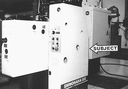
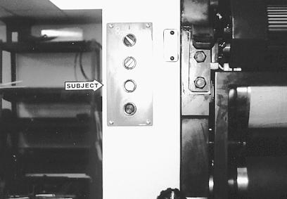
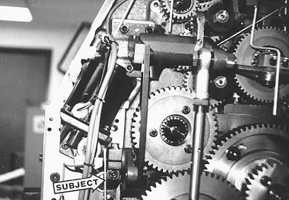
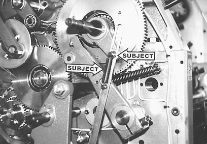
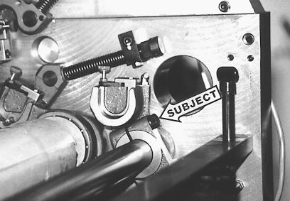
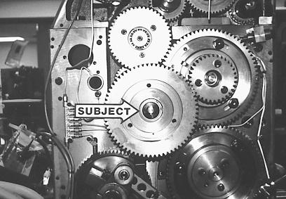
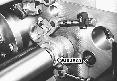
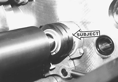
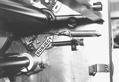
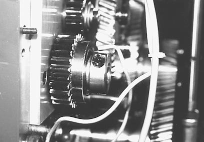
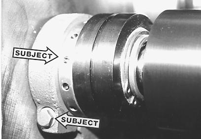
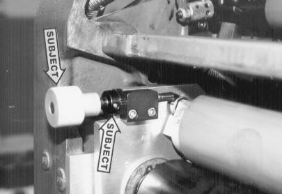
5 DISASSEMBLY 1 Disconnect power supply from press. At OPS, remove all knobs and levers, as well as the steel trim rings, from upper section of the press. Remove all cap screws securing the side cover to the press frame and lift cover from press. It can be placed on the floor beside the press as shown and it will not be necessary to disconnect the control panel wiring harness. 2 At NOPS, the control panel (subject arrow) must be disconnected prior to removing the side cover from the press. Remove the four Phillips head screws securing the panel to the side cover, pull panel out, and unplug the harness. There will also be a conduit nut and plate which fastens the wiring harness to the press cover. Remove these and save for re-installation. Now, remove the cap screws securing the cover to the press and lift off the cover. It is helpful at this point to temporarily reconnect the control panel to the wiring harness to jog the press as needed until the installation is complete. 3 Remove water pan and disconnect all hoses. Also, remove the water form rollers and the ductor roller form the original dampener. 5
6 6
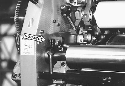
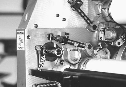
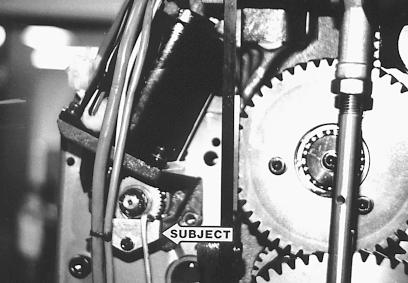
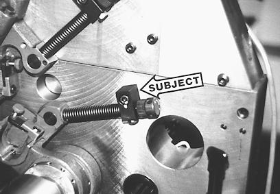
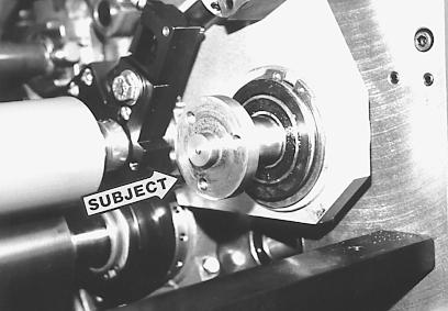
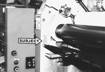
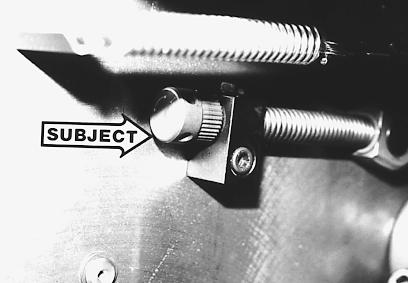
7 DISASSEMBLY 4 Remove pan roller by loosening knurled knob at OPS (subject arrow) and pushing bearing sleeve outward and free of the pan roller journal. Roller may then be lifted out of the press. 5 After pan roller is removed, remove OPS pan roller bearing sleeve assembly from press by removing the two cap screws (subject arrows). 6 At NOPS, loosen cap screws securing the oscillator mechanism (subject arrow) and let mechanism drop down and out of the way of the pan roller drive gear. 7
8 8
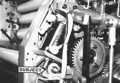
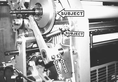
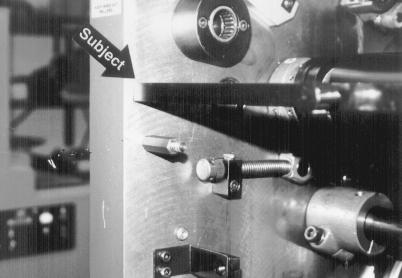
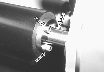
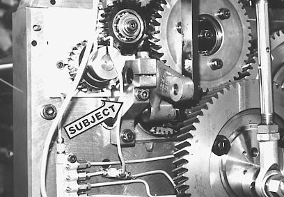
9 DISASSEMBLY 7 Remove oil bath beneath pan roller gear (subject arrow). 8 Remove cotter pin, nut and gear (subject arrows) from the end of the pan roller drive shaft. 9 Disconnect wiring harness from pan roller motor. Remove two cap screws (subject arrows) that secure the motor to the press frame and lift motor off of the press. 9
10 10
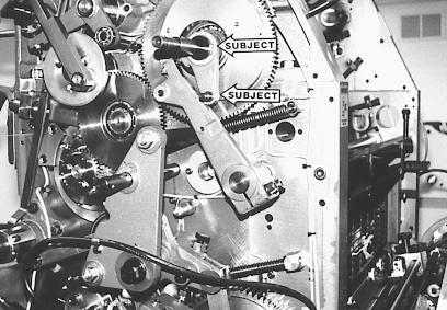
11 DISASSEMBLY 10 At OPS, remove spring (left subject arrow) and snap rings (right subject arrow) from the link arm. Remove the washers that were behind snap rings and pull off link arm. 11 At OPS, remove large snap ring (upper subject arrow) and ductor linkage (lower subject arrow) which is attached to large gear. 12 At OPS, remove extension spring (middle subject arrow). Loosen large cap screws in ductor drive arm (lower subject arrow) and remove arm from ductor shaft. It may help to take a large flat head screw drive and place it in the split of the ductor arm and pry apart slightly. After ductor arm is removed, remove the snap rings from the gear shaft and pull off gear (upper subject arrow). 11
12 12
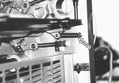
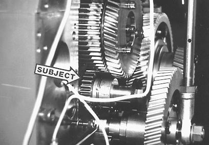
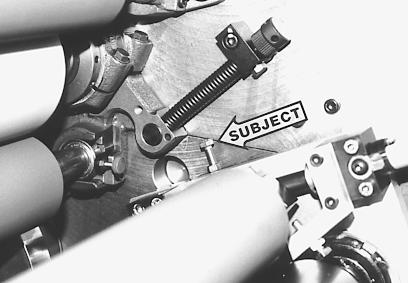
13 DISASSEMBLY 13 Inside the press frames at OPS & NOPS locate extension spring connected to ductor roller carriage and press frame (subject arrow) Disconnect the springs from the press frames. 14 At OPS and NOPS, loosen bolt in ductor roller carriage that clamps it to ductor shaft (subject arrow). Grasp the ductor shaft from outside OPS frame and pull out of press. The ductor roller carriages will slide off end of shaft as it is pulled from the press. 15 At NOPS, locate gear at end of water oscillator (subject arrow) and with a small flat blade screw driver, remove the wire retainer ring from the hub of gear. Exposed will be a taper pin securing the gear to the oscillator journal. Temporarily reconnect the power supply and jog the press until, when viewed from outside NOPS, the small end of the taper pin is at about 10 O clock. Stop the press, disconnect power supply, and do not move it again until instructed. 13
14 14
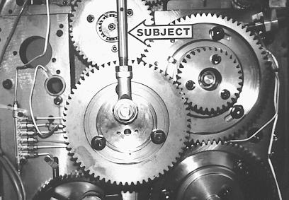
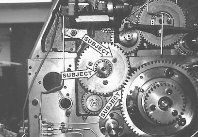
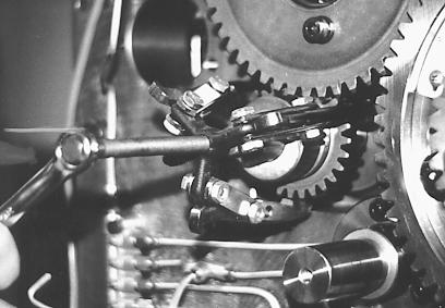
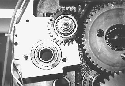
15 DISASSEMBLY 16 Remove oscillator control arm (subject arrow) from large gear. It is secured with a large nut and washer at each end. Save these parts for re-installation. 17 Locate the large gear in photo and place a timing mark between this gear and the smaller gear with which it meshes (right subject arrow). Paint or liquid paper works great. Remove the three hex head bolts (a 17mm socket is helpful here) and lift out center piece of the gear (left subject arrow) Save bolts and center piece for reinstallation. 18 On the gear from last step, remove cap screw and large washer (subject arrow) from center of gear and pull gear off. Save these pieces for re-installation. 15
16 16
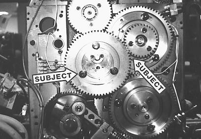
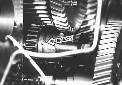
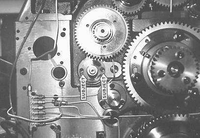
17 DISASSEMBLY 19 Just above gear previously removed is a smaller helical gear connected to the face of a spur gear. As before, place timing marks between this gear and the gear with which it meshes (lower subject arrow). Remove the three cap screws (upper subject arrow) around the gear and the cap screw and washer from the center of the gear (middle subject arrow). You can now pull both this gear off as well as the spur gear that was behind it. A spacer which fits between the gears will also come off. Save all of these pieces for re-installation. 20 Observe again the gear on the end of the oscillator journal. Using a 1/4" blunt punch, drive the pin out of the gear (subject arrow). Some pins are very tight and may need to be drilled out. If so, center punch the pin and with a 5/32" drill bit, slowly drill through the pin. Once the drill bit breaks through the other side, the pin should be easily driven out. After the pin is out, also remove the set screw from the gear hub. 21 Remove the nut and large washer from the end of the oscillator journal. The nut is left hand thread and must be turned clockwise to loosen. You may now remove the gear from the end of the oscillator journal. Sometimes this gear may still be tight even though the pin and set screw is removed, and, therefore, will require a gear puller to remove. 17
18 18
19 DISASSEMBLY 22 On the inside of the press frames, locate the large external snap ring at OPS and NOPS oscillator housing and disconnect (subject arrow). 23 On the inside of the press frames, locate the two water form adjustment mechanisms at OPS and NOPS (subject arrow). They are secured to the press frames with one cap screw each. Remove this screw on all four adjustment mechanisms then push the water form carriages toward the middle of the press until they slide off the oscillator housing. At this point, the snap rings and carriages will hang loosely on the oscillator journals. Save two of the cap screws for re-installation. 24 At OPS and NOPS, remove the two cap screws (subject arrow) from the oscillator housing and pull housing out. The NOPS housing can be completely removed but the OPS housing can only be pulled out until it hits a large plate. Save for re-installation. 19

20 20
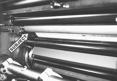
21 DISASSEMBLY 25 Push oscillator all the way toward NOPS. The OPS journal should then clear the press frame and the roller can be lifted out as shown. Once the roller is out of the press, slip off the water form hangers and snap rings. Save for re-installation the outer form hangers and snap rings. (The inner form hangers will not be re-used). It may be helpful to mark the outer form roller hangers as to OPS or NOPS. 26 Remove the tie bar from the press as indicated by the subject arrow in the photo. Save the bolts for installation of a provided new tie bar in a later step. YOU ARE NOW READY TO INSTALL THE CRESTLINE. 21
22 22
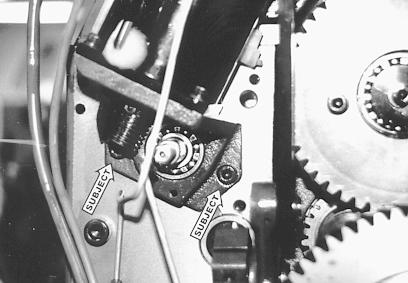
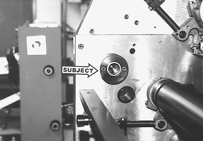
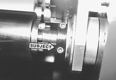
23 INSTALLATION 1 Install new oscillator roller provided by repeating disassembly steps in reverse order with the following exceptions: A. A pulley (subject arrow) is used in place of the original inner form roller hangers removed earlier. B. Do not re-connect oscillator mechanism at NOPS at this time (this was removed in disassembly step 6). Remember, when reinstalling gears to match up all timing marks. Also, it is advisable to leave the protective paper cover on this roller when installing to prevent and nicks or scratches. Remove paper after roller is installed. 2 At NOPS install pan roller bearing housing and secure with 2 provided shallow head cap screws. There is a spur gear attached to this plate, be sure to check the mesh of this gear to the press gear before fully tightening bolts. (Photo shows housing and plate only partially installed). 3 At the OPS, install pan roller bearing housing (subject arrow) as shown with 2 cap screws provided. 23

24 24
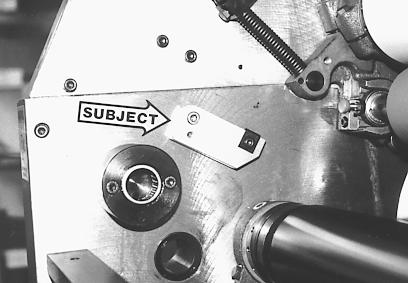
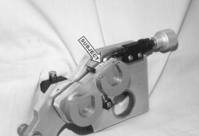
25 INSTALLATION 4 At the OPS & NOPS, install pressure adjustment block (subject arrow) by slipping spool through hole in press frame and securing block with cap screws provided. 5 At OPS & NOPS install dampener side frame assembly as shown. Slip large bronze bushing in the dampener frame over the pan roller bearing housing (subject arrow). Slip large bronze washer over the pan roller bearing housing and up against the dampener frame. Secure the frame with the large snap ring provided. Check for end play in frame. If necessary, remove snap ring and add shim washers provided to tighten fit. NOTE: Actual frame assembly may differ slightly than photo. 6 Install the OPS rider roller mounting bracket as shown in the diagram. The large mounting spool fits in the dutor shaft hole. The spring stud goes through the mounting brackets and threads into a press frame hole directly under the tie bar. Repeat this procedure for the NOPS. 25

26 26
27 INSTALLATION 7 At OPS & NOPS, route cable (subject arrow) attached to dampener side frame around the groove in the pulley installed earlier and attach spring to the stud installed in previous step. 8 At NOPS, slip the provided bronze thrust washer (not visible in photo) over pan roller drive shaft (subject arrow), and slip pan roller drive shaft through bearing housing and push toward outside as far as it will go. 9 Install pan roller (subject arrow) by lowering it into the press and inserting into the OPS bearing housing as far as it will go. While supporting the roller with one hand, push the drive shaft at NOPS until it engages the end of the pan roller. 27
28 28
29 INSTALLATION 10 Rotate the drive shaft until the 3 holes in the drive shaft line up with the 3 holes on the end of the pan roller. Using 3 6mm hex bolts and lock washers provided (subject arrow), secure the drive shaft to the pan roller. 11 Make sure the pan roller is pushed all the way toward OPS. Take provided split set collar (subject arrow) and place around pan roller drive shaft at NOPS. Push collar and washer all the way against bearing housing and tighten both screws securely. Spin pan roller by hand and check for freedom of movement. 12 At outside NOPS at the end of pan roller drive shaft place the following parts in this sequence: (1) Washer, (2) Shaft key, (3) gear with hub pointing out, (4) Washer, (5) Shaft Collar. Reform oil line originally routed to ductor shaft to oil gear just installed. 29

30 30
31 INSTALLATION 13 Reinstall oscillator mechanism (subject arrow) at this time. You may need to shift oscillator roller to one side or the other so that ball bearing on oscillating arm engages properly. 14 Install intermediate roller into the lower hangers on the dampener side frames. Install the caps and secure with the provided hardware. 15 Install metering roller (subject arrow) into upper handgers on the dampener side frames. It is held in place with 2 caps and 2 6mm cap screws. 31
32 32
33 INSTALLATION 16 Install new water form roller provided (subject arrow). It installs exactly as the original. 17 Using the original bolts (saved from disassembly step 26) install the provided tie bar in the same position as the original. Note how the water pan blocks (subject arrow) are facing away from the press. 18 Install the rider roller assembly by sliding the pins (both OPS and NOPS) in toward the center of the press as indicated in the diagram. Place the roller in a position so that the pins will fit into the slots in the rider roller mounting brackets. Make sure that both pins are fully seated in the slots. 33
34 34
35 INSTALLATION 19 Temporarily re-install the dampener activation handle and move lever from off to on several times. The dampener frames should pivot up and down easily without binding. 20 Temporarily re-connect power supply and jog press to check the following: A. No oil lines rubbing moving parts B. New gears mesh properly C. No abnormal noises or binding D. Oscillator moves freely from side to side. E. In OFF position, the top three rollers in the dampener should turn ONLY when press is jogged FORWARD. They should remain idle when the press is jogged backward. 21 Disconnect power supply, remove dampener activation lever, and re-install press side covers. Refer to disassembly steps 1 and 2 if necessary. YOU ARE NOW READY TO MAKE FINAL ADJUSTMENTS 35
36 36
37 FINAL ADJUSTMENTS 1 INK UP DAMPENER Make sure dampener is in the OFF position. Apply a small amount of ink on the dampener oscillator roller only. Turn on press and run for seconds and allow the ink to mill. Only the oscillator and form roller will ink up at this time. I O F Plate Cylinder 2 M P 4 mm OSCILLATOR TO FORM ROLLER PRESSURE After press sits still for seconds, jog press forward while looking at form roller. A stripe or bead line should appear on the form roller which was created by the oscillator, and this stripe should be 4 mm (5/32") wide. To adjust, loosen the hex head bolt (lower subject arrow) on the form roller hanger and, with a pin wrench, turn the bronze eccentric bushing (upper subject arrow). The direction of the turn (increase or decrease) will be shown on a decal on the side frame of the press near the dampener. Continue this process until the proper stripe is obtained. I O F Plate Cylinder M P 3 4 mm FORM ROLLER TO PLATE CYLINDER PRESSURE With a metal plate and proper packing mounted to the plate cylinder, drop the dampener form roller down to the plate and back to off again. This will leave a strip on the plate, and this stripe should be 4 mm (5/32"). This stripe is adjusted exactly as the original dampener by turning the knurled knobs (subject arrow) with a pin wrench. The proper direction is imprinted in the top of each knob. 37
38 38
39 FINAL ADJUSTMENTS 4mm O F Plate Cylinder I M P 4 INTERMEDIATE TO OSCILLATOR ROLLER PRESSURE Temporarily remove the dampener metering roller. Drop the dampener down to the plate cylinder again and back off. In addition to the form roller contacting the plate, the intermediate roller will drop down and contact the oscillator roller. Spin the intermediate roller around by hand to reveal the stripe, which should be 4mm (5/ 32"). To adjust, turn the hex bolt (subject arrow) at OPS and NOPS. Turning the bolt down will decrease the stripe and vice-versa. After stripe is set, re-install the metering roller. 3-4 mm I O F Plate Cylinder M P 5 METERING TO INTERMEDIATE ROLLER With dampener guard open, place single-lever in the "DAMPEN" position and jog the press backwards. Observe the stripe between the metering and intermediate roller. It should be between 1/8"-5/ 32" (3mm-4mm). To adjust loosen set screw that secures the metering roller hanger and rotate hanger toward intermediate roller to increase pressure and vice-versa. Retighten set screw when complete. O Plate Cylinder F I M P 6 5mm MAXIMUM METERING TO PAN ROLLER PRESSURE Rotate the press forward by hand and observe the stripe between the metering and pan roller. It should be 3/16 (5mm). It is adjusted by the large black knurled knobs (upper subject arrow) attached to the top of the dampener. Turning the knobs clockwise will increase the stripe and vice-versa. After the proper stripe has been achieved, spin the ratchet wheels (they are not yet locked to the knurled knobs) until they bottom out on the black block (lower subject arrow). You may have to hold on to the knurled knob with one hand to keep it from moving while spinning down the ratchet wheel. At this point, secure the ratchet wheels to the knurled knobs by tightening the set screws (two in each ratchet wheel). This set the maximum metering roller pressure which will 39 be the driest setting for the dampener.
40 40
41 FINAL ADJUSTMENTS 7 7 Attach feed and drain hoses to pan. Install weir over drain hole and turn on circulator pump. Slowly open supply valve until water flows into the pan. A slow steady flow is all that is required for proper circulation. Avoid feeding water too fast into the pan. YOU ARE NOW READY TO PRINT. 41
42 PLATE CYLINDER 1 Water Form Roller 2 Water Oscillator Roller 3 Crestline Intermediate Roller 4 Crestline Metering Roller 5 Crestline Pan Roller 42
43 OPERATION PANEL CONTROLS FINAL ADJUSTMENTS FINAL BASIC ADJUSTMENTS OPERATION The features of the Shinohara operating levers and electronic control panels change very little with installation of Crestline. Probably the most major change is that the original water ductor is no longer on the press so any related controls will no longer have a function. The manual water form levers will still raise and lower the Crestline, or if press is fully electronic, the Crestline will still sequence properly in the press s automatic modes. PREPARING THE DAMPENER FOR PRINTING A. Make sure all rollers are installed in the Crestline and the knurled metering knobs are screwed clockwise until they stop. B. Apply a very small amount of ink on the dampener oscillator and metering rollers. Turn on press and idle for seconds to mill ink. OPTIONAL: The dampener can be inked after the ink rollers are inked by turning on the press and dropping the ink and water forms to the printing plate. Since the dampener does not yet contain water, the plate will ink up solid and will therefore ink up the dampener. After a very light film of ink has covered the dampener rollers, water can then be turned on and the plate can be cleaned up by turning on the press and dropping the dampener to the plate. C. Attach water pan to mounting blocks and attach feed and drain hose from circulator. Close control valve, turn on pump, and slowly open control valve until a slow trickle of fountain solution flows into the pan. D. Place all ink and water controls in the AUTO mode where applicable. 43
44 FINAL ADJUSTMENTS FINAL BASIC ADJUSTMENTS OPERATION ADJUSTING THE AMOUNT OF WATER DELIVERED TO THE PLATE The amount of water delivered to the printing plate is adjusted by the knurled knobs on top of the dampener. Generally speaking, you should begin all jobs with the knobs turned all the way down. This is the minimum water position for Crestline. Should you require more on the plate, turn the knobs counterclockwise one click at a time until desired water volume is achieved. Typically, when the press is running slowly such as during make-ready, the Crestline may need to be opened up one or two clicks to keep proper moisture on the plate, and, then when production printing speeds are initiated, the metering knobs can be turned back down. FOUNTAIN SOLUTIONS AND ALCOHOL Accel recommends using the manufacturer s instructions for mixing fountain solution. Generally, a ph factor of 4.0 to 4.5 is recommended for most metal plate solutions. Conductivity should be about mmhos above your base water. Alcohol is not required for the Crestline to function properly, but will not harm the dampener if you so desire to use it, provided you keep the ratio under 15 %. Alcohol substitutes may also be used according to the manufacturer s recommendations. 44
45 CLEANING FINAL & ADJUSTMENTS MAINTENANCE WASHING UP THE CRESTLINE Generally speaking, the Crestline must be washed up upon each color change and at the end of the day. The following procedures should be followed: A. Close circulator control valve, remove weir, and allow water pan to drain. If necessary, loosen pan knob at NOPS and drop pan down to aid draining. Turn off circulator pump when pan finishes draining. B. Make sure a metal plate is mounted to plate cylinder. Attach wash-up blade to inker, turn on press and wash inker as normal. When the inker is approximately 50% clean, drop the both the ink and water form rollers to the plate and continue washing the inker. Typically, the dampener will pick up enough solution off the plate to clean itself. Avoid applying excess wash directly to the dampener as most of it will end up in the water pan. An optional method which will prohibit roller wash dripping into the water pan is to turn the knurled knobs on the dampener counterclockwise until the metering roller breaks contact with the pan roller. You can then apply more wash directly to the dampener and wipe the pan roller down by hand. C. When all the ink and water rollers are clean, be sure to wipe the excess wash that may accumulate on the ends of the Crestline rollers. D. Remove water pan and inspect for any excess wash that may have dripped from the dampener rollers. If needed, wipe the pan clean and re-mount. E. If this is the last wash-up of the day, spin the knurled knobs counter-clockwise until the metering roller breaks contact with the pan roller to relieve the pressure. Be sure to spin these knobs back down before beginning the next day. 45
46 CLEANING FINAL & MAINTENANCE ADJUSTMENTS DEGLAZING THE CRESTLINE Periodic deglazing of water-soluble contaminants will be necessary with the Crestline. Typically, once every 2-3 weeks will be sufficient, unless you are running electrostatic plates on a daily basis whereas deglazing should be performed weekly. A 50/50 solution of household ammonia and hot water can be used for deglazing purposes. If you prefer a commercially available deglazer, avoid those containing pumice or gritty substances. Always follow deglazing with straight water and then roller wash. Accel offers a product called COMPOUND X that we recommend for deglazing our system. Contact your dealer or Accel for more information. OILING AND GREASING The dampener either contains maintenance-free ball bearings or will be oiled by the central lubrication system on the press. 46
47 CLEANING & MAINTENANCE CRESTLINE CLEANING & MAINTENANCE CHART Daily Weekly Bi-Weekly Monthly Wash Rollers Deglaze Rollers Metal Plate Users Silvermaster Plate Users Electrostatic Plate Users Grease Gears Inspect Ball Bearings Check Roller Pressures Check Roller Surfaces 47
48 48
49 49
50 50
51 51
52 52
53 53
54 54
55 55
56 56
57 57
58 58
59 59
60 60
61
62
63 11103 Indian Trail, Dallas, TX Phone , Fax Web Site
Crestline Dampening System. Installation Instructions. Ryobi 2700, 2800, 3200, 3200E Itek 950, 960, 975 Parent. X /98 Rev-A
 Crestline Dampening System Installation Instructions Ryobi 2700, 2800, 3200, 3200E Itek 950, 960, 975 Parent X88-30 3/98 Rev-A GENERAL INFORMATION ATTENTION CRESTLINE DAMPENER OWNER! Accel Graphic Systems
Crestline Dampening System. Installation Instructions. Hamada RS34 & VS34 Parent Unit DU34 Upper Unit. For Presses Originally Equipped With
 Crestline Dampening System Installation Instructions Hamada RS34 & VS34 Parent Unit DU34 Upper Unit For Presses Originally Equipped With Molleton Dampeners X88-78 01/2001 Rev-A GENERAL INFORMATION ATTENTION
Crestline Dampening System. Installation Instructions. 4 ROLL DAMPENER Ryobi 3302M Itek 3985 A.B. Dick 9985 X /98
 Crestline Dampening System Installation Instructions 4 ROLL DAMPENER Ryobi 3302M Itek 3985 A.B. Dick 9985 X88-49 1/98 GENERAL INFORMATION ATTENTION CRESTLINE DAMPENER OWNER! Accel Graphic Systems provides
HYDRAULIC CONTROL DETAILS PARTS LIST
 Always give model number, serial number and part number when ordering repair parts. HYDRAULIC CONTROL DETAILS PARTS LIST REF NO. PART NUMBER DESCRIPTION 1 101939 Hydraulic Tank 2 101940 Hydraulic Tank
25000 Series Lo-T TM Butterfly Control Valve Instructions
 November 2001 25000 Series Lo-T TM Butterfly Control Valve Instructions Instruction No. 25.1:IM PRELIMINARY STEPS Before installation, note the flow direction arrow on the valve body. The flow should enter
Operating Instructions
 Operating Instructions Holding the material against the angle gauge slide it into the forming head. Be sure that the material remains against the gauge until work is finished. NOTE: This machine will handle
General Four-Way Operation, Maintenance & Service Manual
 General Four-Way Operation, Maintenance & Service Manual SCOPE Included in the following pages you will find assembly drawings, exploded views, parts lists, assembly tips, operational descriptions and
MODELS 49 RA 49 RAZ 49 RAC
 General Safety and Maintenance Manual MODEL grinder featuring a rear exhaust. Model Number Exhaust Direction REAR Throttle Type (L) Lever or (K) Safety Lever Speed 12000 to 14000 R.P.M (13500rpm is standard)
REPAIR INSTRUCTIONS. Cat. No Cat. No MILWAUKEE ELECTRIC TOOL CORPORATION. SDS Max Demolition Hammer. SDS Max Rotary Hammer
 Cat. No. 9-0 SDS Max Demolition Hammer Cat. No. -0 SDS Max Rotary Hammer MILWAUKEE ELECTRIC TOOL CORPORATION W. LISBON ROAD BROOKFIELD, WISCONSIN 00-0 8-9-0 d 000 8-9-0 d Special Tools Require Forcing
Removing and Replacing the Y-truck
 Service Documentation Removing and Replacing the Y-truck To remove and replace the Y-truck you will need the following tools: 4mm Allen wrench 12mm stamped flat wrench #2 Phillips screwdriver (magnetic
RTI TECHNOLOGIES, INC.
 RTI TECHNOLOGIES, INC. BRC500 & BRC550 Arbor/Spindle Mechanism Adjustment & Service Technical Instructions The arbor/spindle mechanism of the BRC500/550 is designed to be robust for long life. Occasionally
OPERATIONAL MANUAL V1.0. Removing/Replacing Blades
 OPERATIONAL MANUAL V1.0 BLUEROCK WS-212 Wire Stripper Removing/Replacing Blades CAUTION!! IMPORTANT!! DANGER!! WARNING!! DISCONNECT MACHINE FROM POWER BEFORE PROCEEDING!! Estimated Completion Time: 90
MOTORIZED STANDARD SHADE WITH CABLES Installation Instructions
 Tools Needed Drill Measuring Tape Pencil 2 Level Plumb Line ¼ Masonry Drill Bit Hammer Linesmans Pliers Cable Cutters Phillips & Flat-Head Screw Driver 11/32 Socket or Open End Wrench 5/32 Allen Wrench
Cam Handle Service Guide
 Cam Handle Service Guide Page 2. Introduction Page 3. Troubleshooting guide Page 4-5. Adjusting the clamp force Page 6-7. Disassembling, greasing and replacing components Page 8-9. Replacing the post bearings
Electric Skein Winder
 Electric Skein Winder Assembly and Use Package Contents 1 - Triangular Body (w/ motor) 1 - Cross Arm 1 - Left Foot (w/ yarn guide) 1 - Right Foot 1 - Adjustable Finger (w/ yarn clip) 3 - Adjustable Fingers
Side Winder R o u t e r L i f t.
 Woodpeckers PRECISION WOODWORKING TOOLS Side Winder R o u t e r L i f t. INSTALLATION INSTRUCTIONS The wrench handle must be pointing left in order to fully insert or remove it. Lift Wrench Once fully
3.2.3 Rear Door Window and Quarter Window Carrier Assembly
 Tighten all bolts. Tighten bolts marked -1- and -2- in specified sequence. Tightening torque: 8 Nm Remaining bolts can be tightened in any sequence. Insert door window -3- through window recess without
Installation and Assembly - Universal Articulating Swivel Double-Arm for 42" - 60" Plasma Screens
 Installation and Assembly - Universal Articulating Swivel Double-Arm for 42" - 60" Plasma Screens Models: PLAV 70-UNL, PLAV 70-UNL-S PLAV 70-UNLP, PLAV 70-UNLP-S R This product is UL Listed. It must be
Nancy s Knit Knacks LLC 4 Yard Option Upgrade Kit Assembly Instructions and User Manual
 Nancy s Knit Knacks LLC 4 Yard Option Upgrade Kit Assembly Instructions and User Manual Thank you for purchasing our 4 Yard Option (4YO) Upgrade Kit. To install this upgrade you are simply going to assemble
Fig Remove chain cover plate bolts. Fig Remove hammer member. Fig Loosen set screws at base of 12-tooth sprocket.
 Fig. 17.2. Remove chain cover plate bolts. Fig. 17.1. Remove hammer member. Fig. 17.3. Remove chain cover plate. Fig. 17.4. Loosen set screws at base of 12-tooth sprocket. Page 61 Fig. 17.5. Remove socket
It is highly recommended that you use a thread lock compound such as Loctite brand on all threads to keep them from vibrating loose.
 Installation instructions for FC12 Forward Controls for Kawasaki Vulcan 750 It is highly recommended that you use a thread lock compound such as Loctite brand on all threads to keep them from vibrating
Astro-Physics Inc. 400QMD Lubrication/Maintenance Guide
 Astro-Physics Inc. 400QMD Lubrication/Maintenance Guide The following guidelines should be followed to lubricate the three main parts of the 400QMD mount. The QMD stands for Quartz Micro-Drive controller.
ABM International, Inc.
 ABM International, Inc. Lightning Stitch required 1 1.0: Parts List head and motor assembly (Qty. 1) Reel stand (Qty. 1) Needle bar frame clamp (Qty. 1) Motor drive (Qty. 1) 2 Cable harness with bracket
HDL(M)6 Nut/Screw Assembly
6 Nut/Screw Assembly") HDL(M)6 Nut/Screw Assembly Remove, repair, and reassemble the nut and screw assembly in your HDL series double lock vise. In these instructions when we refer to the front of the vise or nut/screw assembly,
HDL(M)6 Nut/Screw Assembly Remove, repair, and reassemble the nut and screw assembly in your HDL series double lock vise. In these instructions when we refer to the front of the vise or nut/screw assembly,
Maintenance Information
 16601023 Edition 2 January 2014 Air Impact Wrench 2705P1 Maintenance Information Save These Instructions Product Safety Information WARNING Failure to observe the following warnings, and to avoid these
H8508 Impact Wrench SERVICE MANUAL. Model (Serial Code FWN) Model (Serial Code FWP)
 Model (Serial Code FWP)") SERVICE MANUAL H8508 Impact Wrench Model 48755 (Serial Code FWN) Model 48760 (Serial Code FWP) Read and understand all of the instructions and safety information in this manual before operating or servicing
SERVICE MANUAL H8508 Impact Wrench Model 48755 (Serial Code FWN) Model 48760 (Serial Code FWP) Read and understand all of the instructions and safety information in this manual before operating or servicing
Hardware and Components:
 Hardware and Components: (A) 4X 5/16 x 1 Carriage Bolt (B) 2X 5/16 x 2-1/4 Carriage Bolt (C) 2X 5/16 x 3-1/4 Hex Bolt (D) 2X 5/16 x 3/4 Hex Bolt (E) 2X 5/16 x 1-1/4 Hex Bolt (F) 5/16 x 2-1/4 Hex Bolt (G)
Metroboard Pulley Replacement Procedure
 Metroboard Pulley Replacement Procedure 1) Remove the two transmission cover screws (1/8 allen driver). Then remove the transmission cover. Note there is a split lock washer and flat washer as well, so
Horizontal and Vertical. Metal Cutting Band Saw MODEL: BS-115
 Horizontal and Vertical Metal Cutting Band Saw MODEL: BS-5 SAFETY. Know your band saw. Read the operator s Manual carefully. Learn the operations, applications and limitation.. Use recommended accessories.
SERIES I MILLING MACHINES
 INSTALLATION, OPERATION, MAINTENANCE, AND PARTS LIST SERIES I MILLING MACHINES TP5260 Revised: August 29, 2005 Manual No. M-450 Litho in U.S.A. Part No. M -0009500-0450 June, 2003 MAINTENANCE PROCEDURES
Model: SCD430 SCD640. Installation & Operation Guide P/N SCD640-95
 Model: SCD430 SCD640 Installation & Operation Guide P/N SCD640-95 Model SCD430 and SCD640 Kurt has two Self-Centering vises, a four-inch jaw width (SCD430) and a six-inch jaw width (SCD640). Jaw opening
DYNATRAC BALL JOINT REBUILD INSTRUCTIONS V5.0
 DYNATRAC PRODUCTS 2007-2018 JEEP JK HEAVY DUTY BALL JOINT JP44-2X3050-C DYNATRAC BALL JOINT REBUILD INSTRUCTIONS V5.0 WARNING: Improper use or installation of this product can cause major failures that
Brother Industries, Ltd. Nagoya, Japan
 4. 2001. This service manual has been compiled for explaining repair procedures of the MODEL XL-6562, XL6452, XR- 46. This was produced based on up-to-date product specifications at the time of issue,
ELECTRIC TOOL CORPORATION
 Cat. No. -0 / Hex Demolition Hammer Cat. No. 0-0 Spline Rotary Hammer MILWAUKEE ELECTRIC TOOL CORPORATION W. LISBON ROAD BROOKFIELD, WISCONSIN 00-0 -9-00 d 000 -9-00 d SpecialTools Require Forcing discs
Installation and Assembly - Universal Articulating Swivel Double-Arm for 42" - 60" Plasma Screens
 Installation and Assembly - Universal Articulating Swivel Double-Arm for 42" - 60" Plasma Screens Models: PLAV 70-UNL, PLAV 70-UNL-S PLAV 70-UNLP, PLAV 70-UNLP-S R This product is UL Listed. It must be
SERVICE PARTS LIST PAGE 1 OF 6 BASE ASSEMBLY SPECIFY CATALOG NO. AND SERIAL NO. WHEN ORDERING PARTS 12" SLIDING COMPOUND MITER SAW
 PAGE 1 OF 6 BASE ASSEMBLY 00 0 CATALOG NO. EXAMPLE: SPECIFY CATALOG NO. AND NO. WHEN ORDERING PARTS 6955-20 1 02-80-0050 Thrust Bearing (1) 2 05-80-0510 M5 x 12mm Flat Head T-20 Screw (5) 3 05-81-0135
Installation instructions for FC14S Forward Controls for Shadow ACE and Aero 1100
 Installation instructions for FC14S Forward Controls for Shadow ACE and Aero 1100 It is highly recommended that you use a thread lock compound such as Loctite brand on all threads to keep them from vibrating
N. 15th Street, Middlesboro, KY FLIP TARP DUMP BODY INSTALLATION INSTRUCTIONS
 1-800-248-7717 1002 N. 15th Street, Middlesboro, KY 40965 FLIP TARP DUMP BODY INSTALLATION INSTRUCTIONS Congratulations on your purchase of a Mountain Flip Tarp Dump Body tarping system. With tarping systems
Coolant Tank Screen Leg Idle End Lockwasher 64 B-015B Leg Drive End Machine Screw 1/4-20 x 3/4 Round Head
 Always give model number, serial number and part number when ordering repair parts. BED, COOLANT & DASH POT PARTS LIST (Cont'd.) REF NO. PART NUMBER DESCRIPTION 19 B-077 Vise Slide Block 20 B-045 Vise
SWAG AIR-HYDRO RAM MOUNT ASSEMBLY INSTRUCTIONS
 SWAG AIR-HYDRO RAM MOUNT ASSEMBLY INSTRUCTIONS Tools needed for assembly: 5/16 HEX KEY WRENCH ¼ HEX KEY WRENCH ¾ SOCKET AND WRENCH 1.125 SOCKET HAMMER FLAT SCREW DRIVER GREASE FOR ASSEMBLY Step #1 Disassemble
DYNATRAC BALL JOINT REBUILD INSTRUCTIONS V4.0
 DYNATRAC PRODUCTS 2007-2016 4X4 JEEP JK HEAVY DUTY BALL JOINT JP44-2X3050-C DYNATRAC BALL JOINT REBUILD INSTRUCTIONS V4.0 WARNING: Improper use or installation of this product can cause major failures
SERVICE PARTS LIST PAGE 1 OF 6 BASE ASSEMBLY SPECIFY CATALOG NO. AND SERIAL NO. WHEN ORDERING PARTS 12" DUAL BEVEL COMPOUND MITER SAW B27B
 PAGE 1 OF 6 BASE ASSEMBLY 00 0 EXAMPLE: Component Parts (Small #) Are Included When Ordering The Assembly (Large #). SPECIFY CATALOG NO. AND NO. WHEN ORDERING PARTS = Part number change from previous service
CORVETTE CORVETTE REV: Made in USA U.S. PATENT #6,808,223; #6,845,547; #7,140,075; #7,059,655 and other patents pending.
 CORVETTE 2005-2006 CORVETTE 2005-2007 REV: 7-2-07 Made in USA U.S. PATENT #6,808,223; #6,845,547; #7,140,075; #7,059,655 and other patents pending. Page 1 of 12 CORVETTE C6 2005-2007 THIS KIT INCLUDES:
TorqueMaster Replacement Spring
 TorqueMaster Replacement Spring Installation Instructions NOTE: Use these installation instructions in conjunction with the TorqueMaster Repair / Replacement Spring Program literature. Copyright 999 Wayne-Dalton
Power Train Lift Max. Capacity: 1,250 lbs.
 655 EISENHOWER DRIVE OWATONNA, MN 55060 USA PHONE: (507) 455-7000 TECH. SERV.: (800) 533-6127 FAX: (800) 955-8329 ORDER ENTRY: (800) 533-6127 FAX: (800) 283-8665 INTERNATIONAL SALES: (507) 455-7223 FAX:
Inventory MODEL T10096 TAPER ATTACHMENT FOR G0509 & G0509G LATHE INSTRUCTIONS. Inventory (Figure 1) Needed Items
 Needed Items") MODEL T10096 TAPER ATTACHMENT FOR G0509 & G0509G LATHE INSTRUCTIONS Inventory The Model T10096 taper attachment was carefully packed when it left our warehouse. If you discover it is damaged after you
MODEL T10096 TAPER ATTACHMENT FOR G0509 & G0509G LATHE INSTRUCTIONS Inventory The Model T10096 taper attachment was carefully packed when it left our warehouse. If you discover it is damaged after you
Inspection. Assembly Install the springs. 1. Discard the 0-rings. 2. Clean all parts in cleaning solvent.
 6010-34 Inspection 3. Install the springs. 1. Discard the 0-rings. 2. Clean all parts in cleaning solvent. 3. If spring test equipment is available, check the tension of each spring according to the specifications
PROSTEER BALL JOINT REBUILD INSTRUCTIONS V1.0
 DYNATRAC PRODUCTS 2003-2010 4X4 DODGE 2500/3500 HEAVY DUTY BALL JOINT PROSTEER BALL JOINT REBUILD INSTRUCTIONS V1.0 WARNING: Improper use or installation of this product can cause major failures that could
Operating Instructions and Parts Manual. 10 x 16 Horizontal Band Saw Models J-7020, J-7040
 Operating Instructions and Parts Manual 10 x 16 Horizontal Band Saw Models J-7020, J-7040 JET 427 New Sanford Road LaVergne, Tennessee 37086 Part No. M-414472 Ph.: 800-274-6848 Revision C2 03/2014 www.jettools.com
Customer Notice: Congratulations again on your SawStop purchase, and thank you! -SawStop Tualatin, OR
 Customer Notice: Congratulations on the purchase of this Sliding Crosscut Attachment. As the owner of a SawStop saw, you are familiar with our high standards for quality, fit and finish. Different from
THE T-MAG II PRESS. Figure 6
 THE T-MAG II PRESS The Lyman T-Mag Press features a powerful compound leverage with a unique position indexable turret and quick disconnect release system. This allows you to mount several die sets, precisely
Gared Pro-S Portable Backstop
 Models: 9616 & 9618 Installation, Operation and Maintenance Instructions Please read all instructions before attempting installation or operation of these units SAVE THESE INSTRUCTIONS FOR FUTURE USE PUBLICATION
The Bowflex Revolution XP Home Gym Assembly Instructions. P/N: Rev ( /0 )
") P/N: 001-7057 Rev ( /0 ) The Bowflex Revolution XP Home Gym Assembly Instructions 2 Table of Contents Before You Start... 2 Tools You Will Need / Hardware Contents... 3 Box Contents... 6 Assembling Your
P/N: 001-7057 Rev ( /0 ) The Bowflex Revolution XP Home Gym Assembly Instructions 2 Table of Contents Before You Start... 2 Tools You Will Need / Hardware Contents... 3 Box Contents... 6 Assembling Your
1 of 2 3/3/2017 4:49 PM
 1 of 2 3/3/2017 4:49 PM Front Door Window, Assembly Overview 1 - Window guide - Inserted on flange 2 - Door 3 - Inner window recess seal - Inserted on flange 4 - Bolt - 20 Nm 5 - Carrier assembly - Window
DRIVE COMPONENTS REMOVAL. 9. FXCW/C: see Figure Remove bolt (9), sprocket retainer (8), and thrust washer (7). NOTE PRIMARY DRIVE LOCKING TOOL
, sprocket retainer (8), and thrust washer (7). NOTE PRIMARY DRIVE LOCKING TOOL") DRIVE COMPONENTS REMOVAL PART NUMBER HD-7977 TOOL NAME PRIMARY DRIVE LOCKING TOOL S To remove the primary chain, remove compensating sprocket, clutch assembly and primary chain as an assembly:. Remove
DRIVE COMPONENTS REMOVAL PART NUMBER HD-7977 TOOL NAME PRIMARY DRIVE LOCKING TOOL S To remove the primary chain, remove compensating sprocket, clutch assembly and primary chain as an assembly:. Remove
Exploded View Saw Base - Model 7060 Semi-Automatic Cut-Off Band Saw
 Exploded View Saw Base - Model 7060 Semi-Automatic Cut-Off Band Saw 136 137 135 134 132 131 133 113 114 115 117 116 118 119 120 121 79 78 77 107 108 65 76 110 109 66 10 9 6 11 5 4 8 7 75 74 73 72 111 112
Instructions for the installation of Ellison Bronze balanced door models #137 & 138
 1. A packing list will be found in crate No. 1 of each shipment. The parts in the crates should be checked with this list. If there is any discrepancy, notify Ellison Bronze at once. 2. All parts are numbered.
Preference Collection and Treatment Console INSTALLATION GUIDE
 Preference Collection 5580.69 and 5580.96 Treatment Console INSTALLATION GUIDE WARNING Failure to install the 5580 as described in this installation guide may cause the unit to collapse, resulting in serious
Click Here to Go Back
 Click Here to Go Back Fig. -94 Fig. -97 CC42D 10. Remove the cap screw securing the gear shift stopper plate pin retainer; then remove the retainer. Fig. -95 CC45D 12. Remove the link arm and account for
AndyMark DART 12.
 AndyMark DART 12 Part Number Description QTY These Parts Are Pre-Assembled by AndyMark am-0031 Bearing, 3/16"ID (R3) 1 am-0209 Bearing, 3/8"ID 1614ZZ 2 am-1028 Screw, #10-32x3/8 Pan Head Philips 8 am-1121
CV1B Sliding Table Installation and Setup Guide
 CV1B Sliding Table Installation and Setup Guide Tech Mark, Inc 7901 Industry Drive North Little Rock, AR 72117 tel (501) 945-9393 fax (501) 945-0312 www.tech-mark.com email: info@tech-mark.com The CV1B
JARVIS. Model Buster V Loin Drop Beef Loin Dropping Saw
 Beef Loin Dropping Saw EQUIPMENT SELECTION... Buster V Loin Drop Saw Ordering No. 230V, 60Hz Model... 4006051 460V, 60Hz Model... 4006060 575V, 60Hz Model... 4006087 Spring Balancer... 4042038 Blade (133
Inventory MODEL H7937 TAPER ATTACHMENT FOR THE G0600 LATHE INSTRUCTIONS. Inventory (Figure 1) Needed Items
 Needed Items") MODEL H7937 TAPER ATTACHMENT FOR THE G0600 LATHE INSTRUCTIONS Inventory The Model H7937 taper attachment was carefully packed when it left our warehouse. If you discover it is damaged after you have signed
MODEL H7937 TAPER ATTACHMENT FOR THE G0600 LATHE INSTRUCTIONS Inventory The Model H7937 taper attachment was carefully packed when it left our warehouse. If you discover it is damaged after you have signed
VARIABLE SPEED WOOD LATHE. Model DB900 INSTRUCTION MANUAL
 VARIABLE SPEED WOOD LATHE Model DB900 INSTRUCTION MANUAL 1007 TABLE OF CONTENTS SECTION...PAGE Technical data.. 1 General safety rules....1-3 Specific safety rules for wood lathe.....3 Electrical information.4
Mechanical Frappe Press
 Mechanical Frappe Press Operation Manual CONTENTS OPERATIONAL INSTRUCTIONS PRECAUTIONS PART NAMES INCLUDED ITEMS BASIC OPERATION MAINTENANCE REPLACEMENT PARTS Thank you for using The Frapptastic Five Mechanical
By C.W. Woodson From the pages of Model Craftsman magazine June, 1937
 By C.W. Woodson From the pages of Model Craftsman magazine June, 1937 As shown in Fig. 1, the tool post grinder for which plans are given here can be used to finish up delicate work to more accurate dimensions
SERVICE PARTS LIST. M18 FUEL SAWZALL Reciprocating Saw F56A BULLETIN NO CATALOG NO
 47(5x) 46 45 00 44 0 59 43 42 84 51 57 46 47 48 59 83 64 77 48 47(2x) 49(2x) 40 58 See service note on page 5 41 82 51 40 41 42 43 44 45 87 52 27 28 34 57 29 (6x) 60 28 EXAMPLE: Component Parts (Small
Replacing the Reciprocator on an SWF Multi-head.
 Replacing the Reciprocator on an SWF Multi-head. Follow the instructions below to replace the reciprocator in the SWF multi-head machines. The tools required are found in the tool kit that came with the
Installation Instructions
 The IMS ETERNAL FIX PATENT PENDING Installation Instructions EPS recommends professional installation for the Eternal IMS Fix. Please take all precautionary safety measures. We also recommend putting the
30DC Speed Lathe Manual
 30DC Speed Lathe Manual The Crozier Model 30DC Speed Lathe is our most popular model. It has many standard features not found on any other machine in its class or price range. Standard Features 3/4 HP
model tsa-sa48 Sliding Crosscut Table installation guide
 model tsa-sa48 Sliding Crosscut Table installation guide A Note About Color Variations Among Anodized Aluminum Components Congratulations on the purchase of this SawStop Sliding Crosscut Table. We at SawStop
Hatchback Wing Riser Kit
 Hatchback Wing Riser Kit 2015-06-11 Thank you for purchasing this PERRIN product for your car! Installation of this product should only be performed by persons experienced with installation of aftermarket
Owner s Manual AE PLUG AERATOR MANUFACTURING QUALITY LAWN CARE EQUIPMENT SINCE Made In CHINA REV
 MANUFACTURING QUALITY LAWN CARE EQUIPMENT SINCE 1945 Owner s Manual AE-48 48 PLUG AERATOR IMPORTANT Read and follow all Safety Precautions and Instructions Before Operating this Equipment. Made In CHINA
Installation Instructions Kit, Base Rail Bracket Part # 31413
 Installation Instructions Kit, Base Rail Bracket Part # 31413 Dealer / Installer: Provide a copy of these Instructions to the end user of this product. These Instructions provide important operating and
OPERATING INSTRUCTIONS 3421UX VETERANS BLVD, CARLSTADT, NJ 07072
 OPERATING INSTRUCTIONS 3421UX5-1 400 VETERANS BLVD, CARLSTADT, NJ 07072 CONTENTS DESCRIPTION... 3 OPERATOR INFORMATION... 5-8 INSTALLATION...... 4 ADJUSTMENT... 8-17 LUBRICATION... 5 INDEX Description
OTECO INC. MODEL ,000 PSI 4-1/16 PORT DM GATE VALVE MAINTENANCE MANUAL
 Page 1 of 7 OTECO INC. MODEL 45 4 5,000 PSI 4-1/16 PORT DM GATE VALVE MAINTENANCE MANUAL Page 2 of 7 TABLE OF CONTENTS 1. Assembly Blowout 2. Repair Kit Contents & Technical Specifications 3. Disassembly
1. Turn off or disconnect power to unit (machine). 2. Push IN the release bar on the quick change base plate. Locking latch will pivot downward.
. 2. Push IN the release bar on the quick change base plate. Locking latch will pivot downward.") Figure 1 Miniature Quick Change Applicators, of the end feed type, are designed to crimp end feed strip terminals to prestripped wires. Each applicator is set up to accept the strip form of certain specific
Figure 1 Miniature Quick Change Applicators, of the end feed type, are designed to crimp end feed strip terminals to prestripped wires. Each applicator is set up to accept the strip form of certain specific
Hardware and Components:
 Hardware and Components: (A) 5/16 x 2 Hex Bolt (B) 5/16 x 2-1/4 Hex Bolt (C) 5/16 x 2-1/2 Hex Bolt (D) 4X 5/16 x 3/4 Hex Bolt (E) 4X 5/16 x 1-1/4 Hex Bolt (F) 11X 5/16 Flat Washer (G) 12X 5/16 Nylock Nut
LX1 Maintenance Manual for Model LX1B. Table of Contents 1. GENERAL DISASSEMBLY, ASSEMBLY AND ADJUSTMENT COMPONENTS...
 KTI KITO Technical Information LX1 Maintenance Manual for Model LX1B LX1-1.1.2 1 / 14 Edition: D 03.06 Table of Contents 1. GENERAL...2 2. DISASSEMBLY, ASSEMBLY AND ADJUSTMENT...2 3. COMPONENTS...3 4.
Lumber Smith. Assembly Manual. If you are having problems assembling the saw and need assistance, please contact us at:
 Lumber Smith Assembly Manual If you are having problems assembling the saw and need assistance, please contact us at: 804-577-7398 info@lumbersmith.com 1 Step 1 Safety Carefully read the Owners Manual.
LORON SERVICE MANUAL / PARTS LIST SINGLE DOUBLE PALLET HANDLER CONTENTS: PAGE 1 Lift Truck Requirements General Installation Procedures
 LORON SERVICE MANUAL / PARTS LIST SINGLE DOUBLE PALLET HANDLER CONTENTS: PAGE 1 Lift Truck Requirements General Installation Procedures 2 Mounting Options Stop Block Adjustments 3 General Weekly Inspection
MantelMount. TM1A Installation Instructions IMPORTANT SAFETY INSTRUCTIONS - SAVE THESE INSTRUCTIONS
 MantelMount TMA Installation Instructions IMPORTANT SAFETY INSTRUCTIONS - SAVE THESE INSTRUCTIONS TM Thank you for choosing the MantelMount television wall mount. Please read this entire manual before
535A. Main Components. Pipe and Bolt Threading Machine. Printed in U.S.A. Ridge Tool Company/Elyria, Ohio, U.S.A.
 Pipe and Bolt Threading Machine A Main Components 0 Screw, Button Head /" - 0 x /" () Washer, Flat /" ()" Top Cover 0 Base Bottom Cover Screw, Pan Head # - x " () Carriage Assembly 0 Front Support Bar
Midwest RDH Handpiece Repair Procedure
 Midwest RDH Handpiece Repair Procedure The Midwest RDH handpiece is fairly common and is used by hygienists to clean teeth. The most common problems for this handpiece include a bad prophy head or a dirty
TRUE TECHNICAL SERVICE MANUAL - ALL MODELS. DOORS/DRAWERS/LIDS
 DOORS/DRAWERS/LIDS 55 56 NOTES DOORS/DRAWERS/LIDS Swing s 73 74 NOTES INSTALLATION OF A GDM-SWING DOOR Phillips Head Screwdriver (2) - 1/8" Drift Punches (forged) Top Bracket NOTE: It may be necessary
JARVIS. Model Buster IV Forequarter Beef Splitting Band Saw Installation Instructions... 9 TABLE OF EQUIPMENT
 Beef Splitting Band Saw EQUIPMENT SELECTION............. Ordering No. TABLE OF CONTENTS......................... Page Buster IV Forequarter Saw.... 4006058 Spring Balancer............. 4042023 Blade......................
2. Inspect the end yoke bores for wear and damage. Replace if necessary.
 SERVICE INSTRUCTIONS BEFORE DOING ANY SERVICE OR MAINTENANCE WORK ON THE MACHINE, YOU MUST: Disengage all power Shut off the tractor engine LOOK and LISTEN! Make sure all moving parts are stopped. Disconnect
400A 40113V, 401A 40120V, & 401AL 40120VL ALUMINUM VERTICAL 4000 LB LIFT INCLUDES SCREW LEG ASSEMBLY INSTRUCTIONS
 12/11/07 PAGE 1 OF 12 400A 40113V, 401A 40120V, & 401AL 40120VL ALUMINUM VERTICAL 4000 LB LIFT INCLUDES SCREW LEG ASSEMBLY INSTRUCTIONS Thank you for purchasing our product! *Please read these instructions
Installation and Assembly: In-wall Mount for 32" to 71" Flat Panel Screens
 Installation and Assembly: In-wall Mount for 32" to 71" Flat Panel Screens Model# IM760P, IM760P-S IM760PU, IM760PU-S Screen size range 32" to 71" (81 to 180 cm) 32" to 60" (81 to 152 cm) IM760P IM760P-S
BEAST THE. Tube and Pipe Notcher Operating Instructions. Notches In Bends Straight Notches. Angled Notches. Offset Notches
 Copyright (c) 2007 J D SQUARED INC. www.jd2.com THE BEAST Tube and Pipe Notcher Operating Instructions Notches In Bends Straight Notches Angled Notches PATENT PENDING Offset Notches Assembly After unpacking
RACER TECH COMMANDER HD TIE ROD INSTALLATION
 RACER TECH COMMANDER HD TIE ROD INSTALLATION NOTE: These instructions are a universal explanation of how to install our HD Tie Rods. All kits are identical for all inner joints and nearly identical for
OPERATION & MAINTENANCE MANUAL
 OPERATION & MAINTENANCE MANUAL AUTOMATIC PECAN CRACKER Food Processing Equipment and Machinery Specializing in the Pecan Industry Mailing: PO Box 817, Mansfield, Louisiana 71052 Located: 280 Independence
JARVIS. Model BR-3 Blade Reconditioner ... EQUIPMENT TABLE OF
 - Model BR-3 Blade Reconditioner EQUIPMENT SELECTION.......... Ordering No. TABLE OF CONTENTS............................ Page Model BR-3 (100 mm Blade) 115V/60Hz............ 4011003 220V/50Hz............
Installation Guide Installation Kit for Mounting Philips MP20/30/40/50 on Datex-Ohmeda Aisys Anesthesia Machine
 Installation Guide Installation Kit for Mounting Philips MP20/30/40/50 on Datex-Ohmeda Aisys Anesthesia Machine The purpose of this guide is to: 1. Describe mounting of Counterweight (page 2). 2. Describe
RULTRACT RETRACTOR CABLE REPLACEMENT INSTRUCTIONS. Rultract, Inc. is the ONLY authorized service center in the U.S.A.
 RULTRACT RETRACTOR CABLE REPLACEMENT INSTRUCTIONS Rultract, Inc. is the ONLY authorized service center in the U.S.A. When your Rultract instrument needs repair or service, contact Rultract Inc. or Rultract
MANUAL DE MONTAJE ASSEMBLY MANUAL AIREADOR DE PLUG AERATOR MODEL # AE-48T. Hardware & Parts Listing Assembly Instructions Maintenance Notes for
 ASSEMBLY MANUAL Hardware & Parts Listing Assembly Instructions Maintenance Notes for 48 PLUG AERATOR MANUAL DE MONTAJE Lista de piezas y tornillería Instrucciones de armado Notas de mantenimiento para
JARVIS. Model Brisket Scissor EQUIPMENT... TABLE OF
 Model 423-17 Brisket Scissor EQUIPMENT SELECTION... Ordering No. TABLE OF CONTENTS... Page Model 423--17... 4037003 Air Filter / Regulator / Lubricator 3022003 Air Hose Assembly... 3059018 Balancer...
Preference Collection 5543 Central Console INSTALLATION GUIDE
 Preference Collection 5543 Central Console INSTALLATION GUIDE WARNING Failure to install the 5543 as described in this installation guide may cause the unit to collapse, resulting in serious injury to
YALE FIGURE 500 & 500R CLOSURE OPERATION AND MAINTENANCE INSTRUCTIONS
 YALE FIGURE 500 & 500R CLOSURE OPERATION AND MAINTENANCE INSTRUCTIONS IMPORTANT INFORMATION Note To Supervisor: Please share this information with your employees and make sure they have received training
MODEL H " BYRD SHELIX CUTTERHEAD INSTRUCTIONS
 MODEL H9291 12" BYRD SHELIX CUTTERHEAD INSTRUCTIONS The Model H9291 12" Byrd Shelix cutterhead is designed to replace the straight-knife cutterhead on the Grizzly jointer Model G0609. The total procedure