Crestline Dampening System. Installation Instructions. 4 ROLL DAMPENER Ryobi 3302M Itek 3985 A.B. Dick 9985 X /98
|
|
|
- Dorothy Burns
- 6 years ago
- Views:
Transcription
1 Crestline Dampening System Installation Instructions 4 ROLL DAMPENER Ryobi 3302M Itek 3985 A.B. Dick 9985 X /98
2 GENERAL INFORMATION ATTENTION CRESTLINE DAMPENER OWNER! Accel Graphic Systems provides parts and service through its authorized distributors and dealers. Therefore, all requests for parts and service should be directed to your local dealer. The philosophy of Accel Graphic Systems is to continually improve all of its products. Written notices of changes and improvements are sent to Accel Graphic Systems' Dealers. If the operating characteristics or the appearance of your product differs from those described in this manual, please contact your local Accel Graphic Systems Dealer for updated information and assistance. Always update your dampener when improvements are made available, especially those related to safety. YOUR AUTHORIZED CRESTLINE DEALER IS: THE SERIAL NUMBER OF YOUR CRESTLINE DAMPENER(S) IS: SAFETY INFORMATION FOR YOUR SAFETY, DO NOT DISENGAGE OR REMOVE ANY GUARDS FROM THE CRESTLINE DAMPENER. THE DAMP- ENER CONTAINS SOME INWARD ROTATING ROLLER NIPS THAT CAN CAUSE INJURY IF LEFT UNGUARDED. 2
3 GENERAL INFORMATION BASIC CONFIGURATION OF CRESTLINE AND ROLLER PRESSURES c. 5/32" - 3/16" (4-5mm) b. 5/32" (4mm) O F M a. 5/32" - 3/16" (4-5mm) P Adjustments a. Metering to Pan b. Metering to Form c. Form to Plate PLATE CYLINDER Roller Description P = Pan M = Metering O = Oscillator F = Form TERMINOLOGY OPS = Operator's Side NOPS = Non Operator's Side TECHNICAL ASSISTANCE For technical assistance during the installation, please contact: ACCEL GRAPHIC SYSTEMS Indian Trail Dallas, TX PHONE (972) FAX (800) accel@dallas.net WEB SITE accelgraphicsystems.com Crestline is covered by U.S. Patents and Patents Pending 3
4 GENERAL INFORMATION REQUIRED TOOLS FOR REMOVAL OF OLD DAMPENER AND INSTALLATION OF CRESTLINE 1. Phillips Screwdriver 2. Standard Screwdriver 3. 1/8" & 3/32" Allen , 3, 4, 5, & 6 mm Allens 5. 8, 10, 13, & 17 mm Wrenches 6. 7/16" Open End Wrench 7. Vise Grips 8. 4 mm Punch 9. Brass Drift 10. 1/8" Punch 11. Hammer 4
5 PRE-INSTALLATION INSTRUCTIONS PRE-INSTALLATION PROCEDURES AND HOW TO PARALLEL THE DAMPENER. 1. Cut the ties holding the rollers and examine the rollers for gouges, scratches or nicks. 2. Check the box and parts boards to make sure all pieces are present and nothing has been damaged in shipment. 3. Check the dampener alignment by setting it on end on a flat surface such as a cutter bed. If dampener rocks, it needs to be realigned. Loosen the tie bar bolt and align the frames on the flat surface. Retighten bolt. 5
6 6
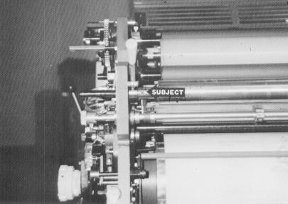
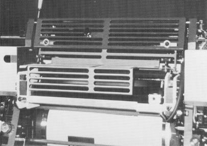
7 DISASSEMBLY 1 DAMPENER REMOVAL (IDENTICAL ON BOTH PRINTING UNITS) Remove guards covering the plate cylinder on both printing units. Save screws for installation of new guards. 2 Remove operating handles and upper side covers from OPS & NOPS sides of the printing head. 3 Remove the small covers over the water control mechanism OPS & NOPS. On older model presses, remove the gray plate that indicated the clicks in ratchet system. 7
8 8
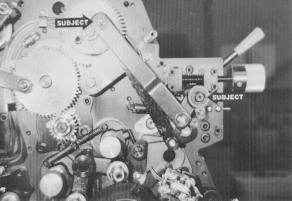
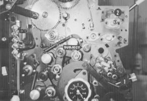
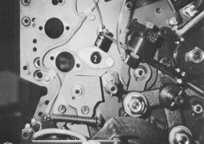
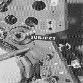
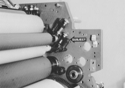
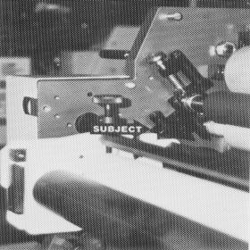
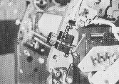
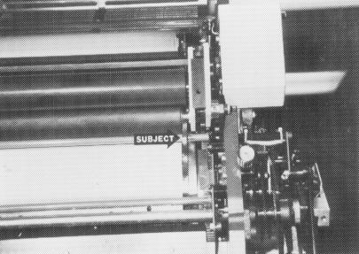
9 DISASSEMBLY 4 Remove the water tray and cloth covered rollers from both printing units. 5 Remove E clips and washers (subject arrows) from stud and pull off the assembly held by these parts. These are located at the OPS. 6 Remove the spring behind the arm (#2 not visible in picture). Remove the E clips and washers (subject arrows) and pull the assembly off. These are located OPS. 9
10 10
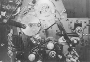
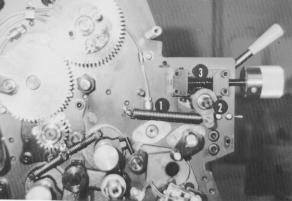
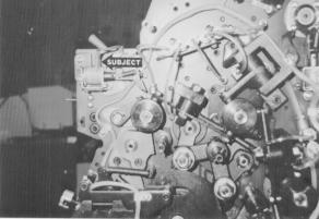
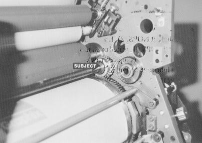
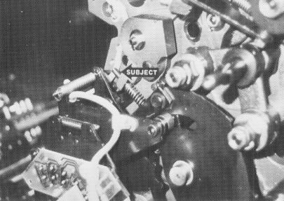
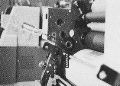
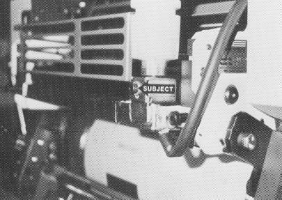
11 DISASSEMBLY 7 Remove the spring (#1), housing with clutch (#2), and infinite water control (#3, held on by 4 bolts) from the end of the water fountain roller shaft. (Older model 2 colors had an arm and ratchet assembly with a gear. Remove these pieces if the press does not have the infinite water control. The gear has a set screw in it that needs to be loosened before you can remove it.) These are located at the OPS. 8 Drive the pin out of the arm (#1) and remove it. Remove the screws near the subject arrows. The arrows on the left indicate the housings for the metal rollers and ductor. The upper arrow, on the right, is the water pan block, the lower arrow is the tie bar bolts. These are at the OPS. NOTE : A new tie bar will be installed in the press during the dampener installation. 9 Remove the long stop pin from the housing on the water form adjustment and screw block (#1) and the bolt from the wiper bar (#2). These are located at the OPS. (On older models, the bolt holding the wiper bar is at the NOPS.) Remove the wiper bar. NOTE : This picture has the parts already removed. 11
12 12
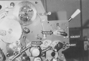
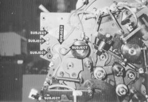
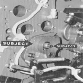
13 DISASSEMBLY 10 Unhook the wires from the solenoid at the NOPS (subject arrow) and remove it from the press. 3 screws hold the solenoid. Each screw has a washer and a spacer. Be sure these parts do not fall in the press. 11 Drive the pin out and remove the arm (subject arrows at far right.) Remove the screws near the other subject arrows except for the one at the very bottom of the page. (Arrow at the bottom of the page has only one screw.) These are at the NOPS. 12 Remove the bolt and spool from the end of the oscillator (subject arrow). The easiest way to do this is: 1. Rotate the press, by hand, until the oscillator has moved all the way to the NOPS. 2. Remove the bolt and lock washer from the end of the oscillator. 3. Remove the oscillator bushing at the OPS and slide the oscillator roller by hand to the OPS. The spool will come off. 13

14 14
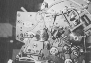
15 DISASSEMBLY 13 Remove the cap screw (subject arrow) holding the two pieces of the water fountain roller together. Remove the bushings from the side frame holding the roller, slide the two pieces apart, and remove the pan roller and extension from the press. (Older model 2 colors have a single piece fountain roller.) 14 Remove the 2 screws and bushing (near #2) for the oscillator at the NOPS. Slide the oscillator roller out of the press. 15 The water ductor mechanism (subject arrow) has a series of set screws holding it to the shaft. Loosen all the set screws, including the one in the brass collar in the middle. Remove the bushings holding the shaft in the side frames. Gently tap the shaft towards the OPS until it clears the inside of the press frame. The entire assembly can be removed. 15
16 16
17 DISASSEMBLY 16 Remove the water form night latch as follows : 1) Put the handle on the shaft at NOPS. 2) Knock the pin out and remove the collar on the shaft at the OPS. (Located outside the side frame.) 3) Loosen the two set screws in the collar (subject arrow). 4) Clean the shaft thoroughly and spray with a lubricant. 5) Pull the shaft towards the NOPS to remove shaft, collar and gear. 17 Loosen set screw (subject arrow) and remove set screw and lock nut (#1). Gently tap inner ring until it is flush with the middle ring. Tighten set screw and replace set screw and lock nut. THIS IS ONLY DONE AT NOPS. 18 Remove the bolt and spring loaded assembly (subject arrow) at OPS & NOPS. 17

18 18
19 DISASSEMBLY 19 Remove the studs (#2) from inside the press frame. There is one stud in the first printing unit and 3 in the second printing unit. YOU ARE NOW READY TO INSTALL CRESTLINE. 19


20 20
21 INSTALLATION 1 Tighten screw (subject arrow) until it is flush with cast metal arm that it is threaded through. This tightens the spring and prevents the entire housing from moving. Screws are located at OPS & NOPS. 2 Reinstall small side covers. On older presses, also install gray plates taken off with the small side covers. (Photo shown with covers on.) Also, note the two holes below the cover (subject arrow). These holes are used in step 3. 3 Install the mounting blocks as shown. Push down on the block when tightening. The bolts are threaded into the holes mentioned in the previous step. 21

22 22
23 INSTALLATION 4 Install the eccentric cams over the ring where the water form shaft from the old dampener was positioned. Each eccentric has two set screws. Only install one set screw st this time. The second one is installed later. Position the cam so the allen wrench is parallel to the mounting block. 5 Place the bolts, mounting spools, and set collars into the mounting blocks as shown (subject arrow). The set collar should be flush against the mounting block and the spool should not extend past the set collar. 6 Slide the front edge of the dampener underneath the casting (subject arrow). Making sure the gears mesh, align the threaded hole in the back of the dampener with the spool installed in the previous step. Place the bolt through the spool and thread it into the hole in the dampener frame. Tighten until the bolt does not turn. After tightening the bolt at both OPS & NOPS, move the set collar (located between dampener frame and mounting block) against the mounting block and tighten. Now, snug up the bolt. CAUTION : Do not overtighten the mounting bolts. This may cause the dampener to be cocked and create gear noise. 23
24 24
25 INSTALLATION 7 Install the tie bar and compression spring at OPS & NOPS as shown (subject arrow). The tie bar rests over the post. 8 Install the compression clip, washer, and bolt as shown (subject arrow). Washer goes between bolt head and clip with pin in the clip in the spring. The cut off corner of the clip goes towards the center of the press. Tighten the bolt thoroughly. 9 Install the small, brass tipped set screw in the threaded hole of the water form adjusting screw block (subject arrow). DO NOT TIGHTEN AT THIS TIME. 25

26 26
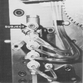
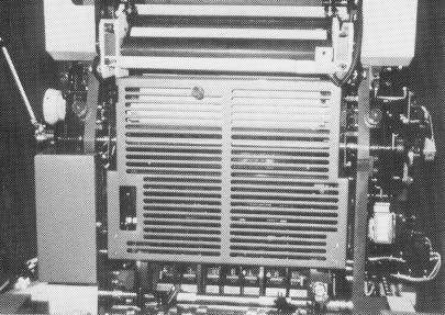
27 INSTALLATION 10 Close off the upper oil lines in the central lubrication system with the pipe plugs and zip ties (subject arrows). OPS side is at left, NOPS at right. NOTE : The solenoid wires are also tied off with the oil line at NOPS. Be sure to wrap them in electrical tape before tying them off. 11 Mount the water pan as shown. Check to make sure the front edge of the pan does not touch the metering/transfer roller of the dampener. If it appears like the roller is going to touch the pan, loosen the pan block bolts (outside of dampener frame) and swing the blocks towards the feed end of the press to lower the front edge of the pan. Use the older water clip to hold the water hose. 12 Install the largest guard on the first printing unit, using the hinges and handle from the previous guard. Install the smallest guard on the second printing unit on the existing hinges. 27
28 28
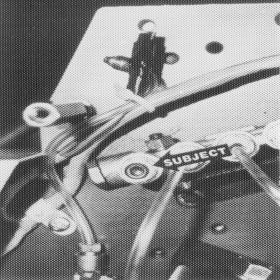
29 INSTALLATION 13 Install the guard over the dampener as shown. 14 Adjust the gear depth of the dampener to the plate cylinder as follows : 1. Place the thick end of the gauge tool between the water form roller shaft and the chrome surface of the plate cylinder. (Gauge shown by subject arrow). 2. Using a long, 1/8" allen wrench, loosen the set screw in the eccentric cam and rotate the cam down until the shaft holds the tool firmly in place. Tighten the set screw. NOTE: Tightening the set screw raises the cam slightly, loosening the gauge. This does not adversely effect the gear depth. 3. Use this procedure at OPS & NOPS of each printing head. When finished, put the second set screw in the eccentric cam. 29

30 30
31 FINAL ADJUSTMENTS 1 Mount a metal plate to both plate cylinders. 2 Dab a small amount of ink on the dampener oscillator and run press at 3000iph to distribute it evenly on all rollers. 3 Drop the dampener to the plate using the operation handle. The dampener drops when moving the handle to the first position (same as with the molletons). An even 5/32" stripe should be used from water form roller to the plate. Turn the water from adjusting knobs (used to adjust pressure of molleton roller to plate) to vary the stripe. Turning the knobs makes a thinner stripe. After getting an even 5/ 32" across the plate, lock the knobs in position using the small set screws installed in step 9 of the dampener installation procedures. 31

32 32
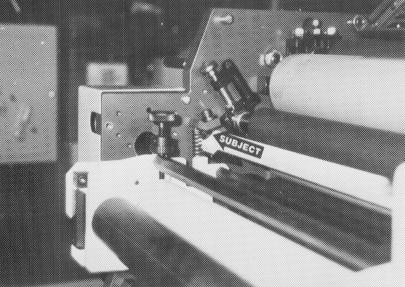
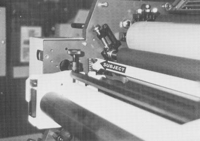
33 FINAL ADJUSTMENTS 4 Set metering pressure between the metering and pan rollers as follows : 1. Spin the ratchet gear (subject arrow) down until it stops against the cross bar. 2. Adjust the knurled knob down until an even 5/32" stripe is obtained between the pan and metering rollers. Always check the stripe on the pan roller. 3. Lock the ratchet gear to the knurled knob by tightening the two set screws in the ratchet gear. (They are brass tipped and should not damage the threads on the knurled knob). 5 Place the water bottle in the bracket with some water in it. Adjust the water height by raising or lowering the bracket with the bolt (subject arrow). The water should be about 1/2 to 3/4 the way up the side of the water pan. 33
34 BASIC OPERATION START OF DAY A. Make sure the oscillator, lower intermediate and metering rollers are in place. B. Spin knurled knobs until the shoulder on the ratchet stops against the stud bar. C. Place water bottle in bracket. NOTE: Accel recommends using the proper fountain solution for the plate material being run on the press. A good acid/gum etch should be used with metal plates. D. Mount plate to cylinder. Wipe down all plates before running. Pre-ink the Crestline dampener before running the plates with an extremely light coverage of ink. Dab the ink on the oscillator only. RUNNING DURING THE DAY A. In general, the Crestline Dampener should not have to be adjusted from job to job. The form roller setting should never be changed unless it has deviated from the factory specification of 5/32" to the plate. B. Adjustments to the amount of water fed to the plate are made by the knurled knobs that apply pressure to the metering roller. The dampener has been set up for minimum water. To increase the water to the plate, turn the knurled knobs counter clockwise 1 or 2 clicks at a time. This opens the gap between the metering and pan rollers and allows more water to the plate. C. In general, more water will only be required when going from a metal plate to an electrostatic or Silvermaster-type plate. 34
35 CLEANING & MAINTENANCE WASH UPS DURING THE DAY 1. Remove bottle and drain the excess water from the pan. 2. Mount a metal plate to the press. 3. Turn on the press and squirt a small amount of press wash on the ink rollers. 4. Drop both the dampener and ink forms to the plate. It will be necessary to drop the forms manually rather than by the single lever. In general, the dampener will pick up enough roller wash off the plate to clean itself. Apply wash directly to the dampener only when necessary. 5. Use wash up attachment as normal. The plate cylinder is being used as a bridge between the dampener and inker. Solution transfers from the dampener to the plate, plate to inker, and inker to wash up attachment. 6. Remove water pan and clean any solution left in it. 7. Be sure to wipe excess clean up solution from the ends of the dampener metering and pan rollers. END OF THE DAY 1. Wash up dampener. Pay close attention to cleaning the ends of the pan and metering rollers that extend past the form rollers. 2. Spin the knurled knobs up until the metering roller can be removed. 3. Remove metering roller and wipe down thoroughly to remove any excess wash that may be on the roller. 35
36 CLEANING & MAINTENANCE DEGLAZING THE DAMPENER Periodic deglazing of water-soluble contaminants will be necessary with the Crestline. Typically, once every 2-3 weeks will be sufficient, unless you are running electrostatic plates on a daily basis whereas deglazing should be performed weekly. A 50/50 solution of household ammonia and hot water can be used for deglazing purposes. If you prefer a commercially available deglazer, avoid those containing pumice or gritty substances. Always follow deglazing with straight water and then roller wash. Accel offers a product called COMPOUND X that we recommend for deglazing our system. Contact your dealer or Accel for more information. OILING AND GREASING THE DAMPENER A. Place a small amount of grease on the gears once a month. B. Inject grease into the oscillator grease fitting once a month. 36
37 CLEANING & MAINTENANCE CRESTLINE CLEANING & MAINTENANCE CHART Daily Weekly Bi-Weekly Monthly Wash Rollers Deglaze Rollers Metal Plate Users Silvermaster Plate Users Electrostatic Plate Users Grease Gears Inspect Ball Bearings Check Roller Pressures Check Roller Surfaces 37
38 38
39 39
40 40
41 41
42 42
43 43
44 44
45
46 11103 Indian Trail, Dallas, TX Phone , Fax Web Site
Crestline Dampening System. Installation Instructions. Ryobi 2700, 2800, 3200, 3200E Itek 950, 960, 975 Parent. X /98 Rev-A
 Crestline Dampening System Installation Instructions Ryobi 2700, 2800, 3200, 3200E Itek 950, 960, 975 Parent X88-30 3/98 Rev-A GENERAL INFORMATION ATTENTION CRESTLINE DAMPENER OWNER! Accel Graphic Systems
Crestline Dampening System. Installation Instructions. Hamada RS34 & VS34 Parent Unit DU34 Upper Unit. For Presses Originally Equipped With
 Crestline Dampening System Installation Instructions Hamada RS34 & VS34 Parent Unit DU34 Upper Unit For Presses Originally Equipped With Molleton Dampeners X88-78 01/2001 Rev-A GENERAL INFORMATION ATTENTION
Crestline Dampening System. Installation Instructions. Shinohara 66. X /98 Rev-A 2598
 Crestline Dampening System Installation Instructions Shinohara 66 X88-58 8/98 Rev-A 2598 GENERAL INFORMATION ATTENTION CRESTLINE DAMPENER OWNER! Accel Graphic Systems provides parts and service through
Inventory MODEL T10096 TAPER ATTACHMENT FOR G0509 & G0509G LATHE INSTRUCTIONS. Inventory (Figure 1) Needed Items
 Needed Items") MODEL T10096 TAPER ATTACHMENT FOR G0509 & G0509G LATHE INSTRUCTIONS Inventory The Model T10096 taper attachment was carefully packed when it left our warehouse. If you discover it is damaged after you
MODEL T10096 TAPER ATTACHMENT FOR G0509 & G0509G LATHE INSTRUCTIONS Inventory The Model T10096 taper attachment was carefully packed when it left our warehouse. If you discover it is damaged after you
N. 15th Street, Middlesboro, KY FLIP TARP DUMP BODY INSTALLATION INSTRUCTIONS
 1-800-248-7717 1002 N. 15th Street, Middlesboro, KY 40965 FLIP TARP DUMP BODY INSTALLATION INSTRUCTIONS Congratulations on your purchase of a Mountain Flip Tarp Dump Body tarping system. With tarping systems
Inventory MODEL H7937 TAPER ATTACHMENT FOR THE G0600 LATHE INSTRUCTIONS. Inventory (Figure 1) Needed Items
 Needed Items") MODEL H7937 TAPER ATTACHMENT FOR THE G0600 LATHE INSTRUCTIONS Inventory The Model H7937 taper attachment was carefully packed when it left our warehouse. If you discover it is damaged after you have signed
MODEL H7937 TAPER ATTACHMENT FOR THE G0600 LATHE INSTRUCTIONS Inventory The Model H7937 taper attachment was carefully packed when it left our warehouse. If you discover it is damaged after you have signed
FLIP TARP SINGLE & DOUBLE UNDERBODY TRAILERS
 1-800-248-7717 1002 N. 15th Street, Middlesboro, KY 40965 FLIP TARP SINGLE & DOUBLE UNDERBODY TRAILERS INSTALLATION INSTRUCTIONS Congratulations on your purchase of a Mountain Flip Tarp Trailer system.
EXIT DEVICE OPERATION FIRE DOOR LABELS, STRIKES AND FRAME SCREWS FOR INFORMATION CALL OR VISIT RITEDOOR.COM
 RECORD & LABELS WHAT THIS OWNER'S CAN DO FOR YOU It explains exactly how The Rite Door operates. It explains periodic maintenance requirements necessary to assure reliable operation. It explains simple
CV1B Sliding Table Installation and Setup Guide
 CV1B Sliding Table Installation and Setup Guide Tech Mark, Inc 7901 Industry Drive North Little Rock, AR 72117 tel (501) 945-9393 fax (501) 945-0312 www.tech-mark.com email: info@tech-mark.com The CV1B
Installation and Assembly - Universal Articulating Swivel Double-Arm for 42" - 60" Plasma Screens
 Installation and Assembly - Universal Articulating Swivel Double-Arm for 42" - 60" Plasma Screens Models: PLAV 70-UNL, PLAV 70-UNL-S PLAV 70-UNLP, PLAV 70-UNLP-S R This product is UL Listed. It must be
HYDRAULIC CONTROL DETAILS PARTS LIST
 Always give model number, serial number and part number when ordering repair parts. HYDRAULIC CONTROL DETAILS PARTS LIST REF NO. PART NUMBER DESCRIPTION 1 101939 Hydraulic Tank 2 101940 Hydraulic Tank
Astro-Physics Inc. 400QMD Lubrication/Maintenance Guide
 Astro-Physics Inc. 400QMD Lubrication/Maintenance Guide The following guidelines should be followed to lubricate the three main parts of the 400QMD mount. The QMD stands for Quartz Micro-Drive controller.
Daily Maintenance. 2. Insert bobbin cases in to rotary hooks. Make sure bobbin thread is not over 2 inches long. Close bobbin case covers.
 Rotary hook 1. Open bobbin case covers and remove bobbin cases. Use brush to remove lint build up in and around rotary hooks. Compressed air may also be used. Daily Maintenance Cle aning Oiling Rotary
Model: SCD430 SCD640. Installation & Operation Guide P/N SCD640-95
 Model: SCD430 SCD640 Installation & Operation Guide P/N SCD640-95 Model SCD430 and SCD640 Kurt has two Self-Centering vises, a four-inch jaw width (SCD430) and a six-inch jaw width (SCD640). Jaw opening
SECTION 9: PARTS. Headstock A 126A 127A-1 REF PART # DESCRIPTION REF PART # DESCRIPTION
 SECTION 9: PARTS Headstock 120 121 113 115 112 111 110 109 108 105 106 107 135 101 119A 121 120 118 114 115 107 106 104 123 122 118 114 126A 105 126 103 102 126B 127A-1 131 127A 124 133 134 126C 129 130
Installation and Assembly - Universal Articulating Swivel Double-Arm for 42" - 60" Plasma Screens
 Installation and Assembly - Universal Articulating Swivel Double-Arm for 42" - 60" Plasma Screens Models: PLAV 70-UNL, PLAV 70-UNL-S PLAV 70-UNLP, PLAV 70-UNLP-S R This product is UL Listed. It must be
SUPER PRO GUN & SUPER PRO GUN II
 MAGNUM VENUS PRODUCTS Maintenance & Repair Manual Part No. M6707-1-1 Revision 04.14.01 Maintenance & Repair Corporate HQ & Mfg. Phone: (727) 573-2955 Fax: (727) 571-3636 Email: info@magind.com Web: www.magind.com
MS25 OPERATION MANUAL
 SAFETY INSTRUCTIONS SPECIFICATIONS OPERATING INSTRUCTIONS MAINTENANCE ADJUSTMENTS REPLACEMENT OF PARTS MS25 DIAGRAM MS25 PARTS LIST MS25 OPERATION MANUAL SAFETY INSTRUCTIONS Please read these instructions
RTI TECHNOLOGIES, INC.
 RTI TECHNOLOGIES, INC. BRC500 & BRC550 Arbor/Spindle Mechanism Adjustment & Service Technical Instructions The arbor/spindle mechanism of the BRC500/550 is designed to be robust for long life. Occasionally
STENCIL MACHINE OPERATION uline.com H-259, H-347 H-408 CUTTING THE OIL BOARD INSERTING THE OIL BOARD
 H-259, H-347 H-408 π STENCIL MACHINE 1-800-295-5510 uline.com OPERATION NOTE: No assembly is necessary after you unpack your machine. INSERTING THE OIL BOARD 1. Move the release lever to the right. This
STEINBERGER TRANSTREM (TYPE 2) TECHNICAL DOCUMENT
 TECHNICAL DOCUMENT") STEINBERGER TRANSTREM (TYPE 2) TECHNICAL DOCUMENT These instructions apply to newer style TransTrems only (non-threaded ball type or modified threaded ball type). For purposes of discussion, these TransTrems
STEINBERGER TRANSTREM (TYPE 2) TECHNICAL DOCUMENT These instructions apply to newer style TransTrems only (non-threaded ball type or modified threaded ball type). For purposes of discussion, these TransTrems
Ringblaster Mark IV Maintenance Guide. Version 1.5
 Ringblaster Mark IV Maintenance Guide Version 1.5 WARNING Winchester Industrial Equipment and Loads must be properly stored, handled and maintained for safe and proper function. Mishandling or failure
SERVICE MANUAL AND PARTSLIST
 SERVICE MANUAL AND PARTSLIST Next 20 CONTENTS WHAT TO DO WHEN... 1~3 SERVICE ACCESS FACE COVER... 4 TOP COVER... 4 BASE COVER... 5 REAR COVER... 6 FRONT COVER... 7 MECHANICAL ADJUSTMENT NEEDLE THREAD TENSION...
Click Here to Go Back
 Click Here to Go Back Fig. -94 Fig. -97 CC42D 10. Remove the cap screw securing the gear shift stopper plate pin retainer; then remove the retainer. Fig. -95 CC45D 12. Remove the link arm and account for
LSU Duct Liner Sizer. LSU Duc DUCT LINER SIZER MACHINERY DIVISION OWNER S MANUAL
 LSU Duct Liner Sizer LSU Duc DUCT LINER SIZER OWNER S MANUAL MACHINERY DIVISION ASSEMBLY INSTRUCTIONS IMPORTANT: DO NOT TIGHTEN THE NUTS UNTIL THE UNIT IS COMPLETELY ASSEMBLED. A) Assemble the cutting
Replacing the build plate clamps
 Repair manual Replacing the build plate clamps Instructions The build plate clamps hold the glass plate in place on the heated bed. There are two fixed in place at the back of the heated bed and two at
CORVETTE CORVETTE REV: Made in USA U.S. PATENT #6,808,223; #6,845,547; #7,140,075; #7,059,655 and other patents pending.
 CORVETTE 2005-2006 CORVETTE 2005-2007 REV: 7-2-07 Made in USA U.S. PATENT #6,808,223; #6,845,547; #7,140,075; #7,059,655 and other patents pending. Page 1 of 12 CORVETTE C6 2005-2007 THIS KIT INCLUDES:
Preference Collection and Treatment Console INSTALLATION GUIDE
 Preference Collection 5580.69 and 5580.96 Treatment Console INSTALLATION GUIDE WARNING Failure to install the 5580 as described in this installation guide may cause the unit to collapse, resulting in serious
Installation Instructions
 Contents Page General Information and Installer Tips.......... 2 Panels & Posts............................. 3 Enclosure Description..................... 4 Hinge Door Hardware................... 4-5 Step-by-Step
Hydraulic Clamp Carrier. Installation & Operation Manual
 Hydraulic Clamp Carrier Installation & Operation Manual Hydraulic Clamp Carrier Installation & Operation Manual Quick Machinery Company 8272 Peninsula Drive Kelseyville, CA 95451 phone: (707) 272-6719
Operating Instructions
 Operating Instructions Holding the material against the angle gauge slide it into the forming head. Be sure that the material remains against the gauge until work is finished. NOTE: This machine will handle
LSU Duct Liner Sizer. LSU Duct UCT LINER SIZER MACHINERY DIVISION OWNER S MANUAL
 LSU Duct Liner Sizer LSU Duct LDUC UCT LINER SIZER OWNER S MANUAL MACHINERY DIVISION assembly Instructions IMPORTANT: DO NOT TIGHTEN THE NUTS UNTIL THE UNIT IS COMPLETELY ASSEMBLED. A) Assemble the cutting
Replacing the Reciprocator on an SWF Multi-head.
 Replacing the Reciprocator on an SWF Multi-head. Follow the instructions below to replace the reciprocator in the SWF multi-head machines. The tools required are found in the tool kit that came with the
Side Winder R o u t e r L i f t.
 Woodpeckers PRECISION WOODWORKING TOOLS Side Winder R o u t e r L i f t. INSTALLATION INSTRUCTIONS The wrench handle must be pointing left in order to fully insert or remove it. Lift Wrench Once fully
Motorized M3 AX7200 Rotary-Style Gasket Cutter Operating Instructions
 Motorized M3 AX7200 Rotary-Style Gasket Cutter Operating Instructions INTRODUCTION Congratulations! You are the owner of the finest rotary-style gasket cutter in the world. Originally developed and patented
Gared Pro-S Portable Backstop
 Models: 9616 & 9618 Installation, Operation and Maintenance Instructions Please read all instructions before attempting installation or operation of these units SAVE THESE INSTRUCTIONS FOR FUTURE USE PUBLICATION
INSTALLATION GUIDE 2009-CURRENT HUMMER H3T PRODUCT CODE:
 INSTALLATION GUIDE 2009-CURRENT HUMMER H3T PRODUCT CODE: 268 June 22, 2010 TOOLS NEEDED COMPONENTS INCLUDED P2 Tip 3/8" Drill Rubber Gasket(s) x 2 Bracket(s) x 2 1/2" Drill Bit Bulkhead Flange #2 Phillips
Installation and Assembly: In-wall Mount for 32" to 71" Flat Panel Displays
 Installation and Assembly: In-wall Mount for 32" to 71" Flat Panel Displays Model# Display size range IM760P, IM760P-S 32" to 71" (81 to 180 cm) IM760PU, IM760PU-S 32" to 65" (81 to 165 cm) This product
SERVICE PARTS LIST PAGE 1 OF 6 BASE ASSEMBLY SPECIFY CATALOG NO. AND SERIAL NO. WHEN ORDERING PARTS 12" DUAL BEVEL COMPOUND MITER SAW B27B
 PAGE 1 OF 6 BASE ASSEMBLY 00 0 EXAMPLE: Component Parts (Small #) Are Included When Ordering The Assembly (Large #). SPECIFY CATALOG NO. AND NO. WHEN ORDERING PARTS = Part number change from previous service
Removing Right-Side. Components. Right-Side. Components. Click Here to Go Back AT THIS POINT
 Click Here to Go Back NOTE: There is an oil passage beneath the driven gear/drive gear assembly. This passage should be plugged prior to removing the driven gear and drive gear. Failure to do so could
Midwest RDH Handpiece Repair Procedure
 Midwest RDH Handpiece Repair Procedure The Midwest RDH handpiece is fairly common and is used by hygienists to clean teeth. The most common problems for this handpiece include a bad prophy head or a dirty
Preference Collection 5543 Central Console INSTALLATION GUIDE
 Preference Collection 5543 Central Console INSTALLATION GUIDE WARNING Failure to install the 5543 as described in this installation guide may cause the unit to collapse, resulting in serious injury to
Fig Remove chain cover plate bolts. Fig Remove hammer member. Fig Loosen set screws at base of 12-tooth sprocket.
 Fig. 17.2. Remove chain cover plate bolts. Fig. 17.1. Remove hammer member. Fig. 17.3. Remove chain cover plate. Fig. 17.4. Loosen set screws at base of 12-tooth sprocket. Page 61 Fig. 17.5. Remove socket
LS2-B891 LT2-B892 LS2-B891-05, LT2-B892-05
 LS2-B891 LT2-B892 Single Needle Unison Feed Lock Stitcher Single Needle Unison Feed Lock Stitcher with Thread Trimmer Twin Needle Unison Feed Lock Stitcher Twin Needle Unison Feed Lock Stitcher with Thread
SERVICE PARTS LIST PAGE 1 OF 6 BASE ASSEMBLY SPECIFY CATALOG NO. AND SERIAL NO. WHEN ORDERING PARTS 12" SLIDING COMPOUND MITER SAW
 PAGE 1 OF 6 BASE ASSEMBLY 00 0 CATALOG NO. EXAMPLE: SPECIFY CATALOG NO. AND NO. WHEN ORDERING PARTS 6955-20 1 02-80-0050 Thrust Bearing (1) 2 05-80-0510 M5 x 12mm Flat Head T-20 Screw (5) 3 05-81-0135
THIS KIT INCLUDES: 8 M8-1.25X40MM BOLTS WITH WASHERS 8 M8-1.25X30MM BOLTS WITH WASHERS RIGHT AND LEFT HINGE
 Sal es@lambodoorscanada. com 2407A Kal adarave,ottawa,on K1V 8B9 THIS KIT INCLUDES: 8 M8-1.25X40MM BOLTS WITH WASHERS 8 M8-1.25X30MM BOLTS WITH WASHERS RIGHT AND LEFT HINGE 2 SHOCKS 565 PSI 2 SHOULDER
Maintenance & Parts list for:
 Maintenance & Parts list for: Industrial gun GB 2 Juni 2017 This Maintenance & Parts list for industrial gun is prepared by : Winchester Europe Service V. Parbst & Søn as a comprehensive maintenance guide
MantelMount. TM1A Installation Instructions IMPORTANT SAFETY INSTRUCTIONS - SAVE THESE INSTRUCTIONS
 MantelMount TMA Installation Instructions IMPORTANT SAFETY INSTRUCTIONS - SAVE THESE INSTRUCTIONS TM Thank you for choosing the MantelMount television wall mount. Please read this entire manual before
FACTORY CAT TOMCAT CORPORATION
 FACTORY CAT RPS TOMCAT CORPORATION Artificial Turf and Carpet Sweeping Install Kit #349-641 & #349-642 1. Detach batteries so that there is no power running through the machine before starting. 2. Start
 488 PARTS LIST 1 3 SCREWS FOR NO. 2 2 FLYWHEEL CAP 3 FLYWHEEL 4 END NUT FOR NO. 10 5 BALL BEARING FOR NO. 3 (1 st ) 6 BALLBEARING FOR NO. 3 (2nd) 7A CLUTCH RACE KEY 7B CLUTCH RACE 7C CLUTCH SPRING 7D 7
M4 Foot Operated Underpinner Instruction Manual
 M4 Foot Operated Underpinner Instruction Manual M4 Walker Rd, Bardon Hill, Coalville, Leicestershire LE67 1TU, England Tel. +44 (0)130 1692, Fax +44 (0)130 16929 e mail sales@framerscorner.co.uk M4 Underpinner
LPK1550 Hydraulic Crimping Tool 15-ton
 SERVICE MANUAL LPK1550 Hydraulic Crimping Tool 15-ton Serial Code FYF Read and understand all of the instructions and safety information in this manual before operating or servicing this tool. Register
SINGER 531B-8BL. From the library of: Superior Sewing Machine & Supply LLC
 SINGER 53B-8BL PERSPECTIVE THREAD TENSION, GUIDE, NEEDLE PLATE i SINGER 4 THREAD TENSION, GUIDE, NEEDLE PLATE 3 Fig. No. Parts No. Quantity Name of Parts Fig. No. Parts No. Quantity Name of Parts 0698
Quick-Release Front Vise 05G34.01
 Quick-Release Front Vise 05G34.01 Patent Pending Introduction A front vise is the most generally useful vise on a typical workbench. It can be used for clamping parts on edge within the jaws, for clamping
CONTENTS PRECAUTIONS BEFORE STARTING OPERATION PREPARATION FOR OPERATION CAUTIONS ON USE OPERATION
 CONTENTS PRECAUTIONS BEFORE STARTING OPERATION ------------------------------------- 1 PREPARATION FOR OPERATION 1. Adjustment of needle bar stop position ---------------------------------------------------------
WX8800 WX8700 LX5801 WX8842 WX MC30
 WX8800 WX8700 LX5801 WX8842 WX8842-1 MC30 First published : August 1991 Third edition : August 2004 No. 040037 INTRODUCTION Thank you for your purchasing Kansai Special's WX Series. Read and study this
ETCHING PRESS MANUAL
 ETCHING PRESS MANUAL FOR ALL SPEEDBALL ETCHING PRESSES Updated October 2018 TABLE OF CONTENTS Delivery Notes 3 Unpacking 4 Floor Stands 6 Safety Tips 6 Maintenance 7 Diagram 8 Warranty Card 9 2 This manual
1. Turn off or disconnect power to unit (machine). 2. Push IN the release bar on the quick change base plate. Locking latch will pivot downward.
. 2. Push IN the release bar on the quick change base plate. Locking latch will pivot downward.") Figure 1 Miniature Quick Change Applicators, of the end feed type, are designed to crimp end feed strip terminals to prestripped wires. Each applicator is set up to accept the strip form of certain specific
Figure 1 Miniature Quick Change Applicators, of the end feed type, are designed to crimp end feed strip terminals to prestripped wires. Each applicator is set up to accept the strip form of certain specific
The Bowflex Revolution XP Home Gym Assembly Instructions. P/N: Rev ( /0 )
") P/N: 001-7057 Rev ( /0 ) The Bowflex Revolution XP Home Gym Assembly Instructions 2 Table of Contents Before You Start... 2 Tools You Will Need / Hardware Contents... 3 Box Contents... 6 Assembling Your
P/N: 001-7057 Rev ( /0 ) The Bowflex Revolution XP Home Gym Assembly Instructions 2 Table of Contents Before You Start... 2 Tools You Will Need / Hardware Contents... 3 Box Contents... 6 Assembling Your
Hardware and Components:
 Hardware and Components: (A) 4X 5/16 x 1 Carriage Bolt (B) 2X 5/16 x 2-1/4 Carriage Bolt (C) 2X 5/16 x 3-1/4 Hex Bolt (D) 2X 5/16 x 3/4 Hex Bolt (E) 2X 5/16 x 1-1/4 Hex Bolt (F) 5/16 x 2-1/4 Hex Bolt (G)
USER MANUAL & PARTS LIST MODEL 136A S/N:
 NUMBERALL STAMP & TOOL CO., INC. USER MANUAL & PARTS LIST MODEL 136A S/N: P.O. BOX 187, 1 HIGH ST. SANGERVILLE, ME 04479 www.numberall.com office@numberall.com TEL: 207-876-3541 FAX: 207-876-3566 MODEL
Ideal 1000 Manual
 Ideal 1000 Manual 20016-6111 Contents 1. Introduction.................................................................... 2 1.0 Introduction................................................................
Preference Collection 5580 Treatment Console INSTALLATION GUIDE
 Preference Collection 5580 Treatment Console INSTALLATION GUIDE 0 WARNING Failure to install the 5580 as described in this installation guide may cause the unit to collapse, resulting in serious injury
WARNING: Prior to installation, turn the power off to the vending machine and unplug it from its power source. Also, make sure to level the machine.
 Installation of Gum and Mint Tray for National 147, 157, 167 Important Note: Please read all instructions thoroughly before continuing with installation of kit. If you are having problems installing the
HDL(M)6 Nut/Screw Assembly
6 Nut/Screw Assembly") HDL(M)6 Nut/Screw Assembly Remove, repair, and reassemble the nut and screw assembly in your HDL series double lock vise. In these instructions when we refer to the front of the vise or nut/screw assembly,
HDL(M)6 Nut/Screw Assembly Remove, repair, and reassemble the nut and screw assembly in your HDL series double lock vise. In these instructions when we refer to the front of the vise or nut/screw assembly,
Installation and Assembly: In-wall Mount for 32" to 71" Flat Panel Screens
 Installation and Assembly: In-wall Mount for 32" to 71" Flat Panel Screens Model# IM760P, IM760P-S IM760PU, IM760PU-S Screen size range 32" to 71" (81 to 180 cm) 32" to 60" (81 to 152 cm) IM760P IM760P-S
M14 MODULAR CHASSIS SYSTEM (MOD 1) INSTRUCTION MANUAL. West Springfield, MA Phone: (866) FAX: (413)
 INSTRUCTION MANUAL. West Springfield, MA Phone: (866) FAX: (413)") M14 MODULAR CHASSIS SYSTEM (MOD 1) INSTRUCTION MANUAL Troy Industries, Inc. WWW.TROYIND.COM West Springfield, MA 01089 Phone: (866) 788-6412 FAX: (413) 383-0339 Thank You M14/M1A MODULAR CHASSIS SYSTEM
M14 MODULAR CHASSIS SYSTEM (MOD 1) INSTRUCTION MANUAL Troy Industries, Inc. WWW.TROYIND.COM West Springfield, MA 01089 Phone: (866) 788-6412 FAX: (413) 383-0339 Thank You M14/M1A MODULAR CHASSIS SYSTEM
25000 Series Lo-T TM Butterfly Control Valve Instructions
 November 2001 25000 Series Lo-T TM Butterfly Control Valve Instructions Instruction No. 25.1:IM PRELIMINARY STEPS Before installation, note the flow direction arrow on the valve body. The flow should enter
Water Line and Water Line Assembly Gasket
 1 Preparation for Repair 1) Remove tip from scaler 2) Remove scaler from air supply 3) Remove gasket from back end of scaler. Examine gasket for obvious wear or disfigurement. Replace if necessary. 2 Remove
MOTOR & BULK HEAD. A Manual for Repair and Maintenance Technicians
 MOTOR & BULK HEAD A Manual for Repair and Maintenance Technicians CAUTION This manual is designed to help technicians who are already experienced in workshop procedures and know how to handle tools. Only
Maintenance Information
 16601023 Edition 2 January 2014 Air Impact Wrench 2705P1 Maintenance Information Save These Instructions Product Safety Information WARNING Failure to observe the following warnings, and to avoid these
M14 MODULAR CHASSIS SYSTEM (MOD 1) INSTRUCTION MANUAL. West Springfield, MA Phone: (866) FAX: (413)
 INSTRUCTION MANUAL. West Springfield, MA Phone: (866) FAX: (413)") M14 MODULAR CHASSIS SYSTEM (MOD 1) INSTRUCTION MANUAL Troy Industries, Inc. WWW.TROYIND.COM West Springfield, MA 01089 Phone: (866) 788-6412 FAX: (413) 383-0339 Thank You M14/M1A MODULAR CHASSIS SYSTEM
M14 MODULAR CHASSIS SYSTEM (MOD 1) INSTRUCTION MANUAL Troy Industries, Inc. WWW.TROYIND.COM West Springfield, MA 01089 Phone: (866) 788-6412 FAX: (413) 383-0339 Thank You M14/M1A MODULAR CHASSIS SYSTEM
SERIES I MILLING MACHINES
 INSTALLATION, OPERATION, MAINTENANCE, AND PARTS LIST SERIES I MILLING MACHINES TP5260 Revised: August 29, 2005 Manual No. M-450 Litho in U.S.A. Part No. M -0009500-0450 June, 2003 MAINTENANCE PROCEDURES
H8508 Impact Wrench SERVICE MANUAL. Model (Serial Code FWN) Model (Serial Code FWP)
 Model (Serial Code FWP)") SERVICE MANUAL H8508 Impact Wrench Model 48755 (Serial Code FWN) Model 48760 (Serial Code FWP) Read and understand all of the instructions and safety information in this manual before operating or servicing
SERVICE MANUAL H8508 Impact Wrench Model 48755 (Serial Code FWN) Model 48760 (Serial Code FWP) Read and understand all of the instructions and safety information in this manual before operating or servicing
B-Too Drilling and Tapping Machine Instruction and Maintenance Manual
 B-Too Drilling and Tapping Machine Instruction and Maintenance Manual Thank you for your purchase of the B-Too Drilling and Tapping Machine. Please read and understand this short operation manual. Our
Coolant Tank Screen Leg Idle End Lockwasher 64 B-015B Leg Drive End Machine Screw 1/4-20 x 3/4 Round Head
 Always give model number, serial number and part number when ordering repair parts. BED, COOLANT & DASH POT PARTS LIST (Cont'd.) REF NO. PART NUMBER DESCRIPTION 19 B-077 Vise Slide Block 20 B-045 Vise
UNPACKING. Thank you for purchasing the Manual Capsule Filling Machine from KARISHMA PHARMA MACHINES.
 UNPACKING Thank you for purchasing the Manual Capsule Filling Machine from KARISHMA PHARMA MACHINES. Please take sufficient time and read this manual carefully before you start installation and operation
OPERATIONS MANUAL. Port-O-Slitter
 Tapco Products Company The World Leader in Specialty Tools for the Professional Port-O-Slitter OPERATIONS MANUAL General instructions, set up, accessories and guide to using your portable precision slitting,
Electric Skein Winder
 Electric Skein Winder Assembly and Use Package Contents 1 - Triangular Body (w/ motor) 1 - Cross Arm 1 - Left Foot (w/ yarn guide) 1 - Right Foot 1 - Adjustable Finger (w/ yarn clip) 3 - Adjustable Fingers
Main Drive Components
 Pipe and Bolt Threading Machine Main Drive Components 0 0 Rear Centering Head Centering Jaw Set Spiral Pins () 00 Centering Scroll Retaining Ring 0 Rear Bearing 0 Oil Ball Valve () # - x / Screw Motor
This instruction manual is an in-depth look and explanation of how to assemble and install the Murphy Bed properly and efficiently.
 This instruction manual is an in-depth look and explanation of how to assemble and install the Murphy Bed properly and efficiently. Don t be put off by the size of the instruction manual as the large diagrams
EZ-HAUL GARDEN CRATE WAGON
 099 EZ-HAUL GARDEN CRATE WAGON 855 00 FarmTek All Rights Reserved. Reproduction is prohibited without permission. STK# Description 099 Garden Wagon Revision date: 09.0.0 CARE AND MAINTENANCE READ THIS
Installation Instructions
 The IMS ETERNAL FIX PATENT PENDING Installation Instructions EPS recommends professional installation for the Eternal IMS Fix. Please take all precautionary safety measures. We also recommend putting the
QB78 CO 2 Pellet Rifle
 QB78 CO 2 Pellet Rifle Maintenance Instructions Text and photos by George Fox Lang The Chinese QB78 pellet rifle is one of the nicest and most popular CO 2 rifles ever produced. Here are the long-wanted
3D PRINTER. Pack 11. Anything you can imagine, you can make! 3D technology is now available for you at home! BUILD YOUR OWN
 BUILD YOUR OWN Pack 11 Anything you can imagine, you can make! 3D PRINTER Compatible with Windows 7 & 8 Mac OS X 3D technology is now available for you at home! BUILD YOUR OWN 3D PRINTER CONTENTS PACK
Topo Freestanding Applications - Private Office
 4 3 2 Topo Freestanding Applications - Private Office Combo Wrench If you have a problem, question, or request, call your local dealer, or Coalesse at 1.800.627.6770 Or visit our website: www.coalesse.com
YALE FIGURE 500 & 500R CLOSURE OPERATION AND MAINTENANCE INSTRUCTIONS
 YALE FIGURE 500 & 500R CLOSURE OPERATION AND MAINTENANCE INSTRUCTIONS IMPORTANT INFORMATION Note To Supervisor: Please share this information with your employees and make sure they have received training
RULTRACT RETRACTOR CABLE REPLACEMENT INSTRUCTIONS. Rultract, Inc. is the ONLY authorized service center in the U.S.A.
 RULTRACT RETRACTOR CABLE REPLACEMENT INSTRUCTIONS Rultract, Inc. is the ONLY authorized service center in the U.S.A. When your Rultract instrument needs repair or service, contact Rultract Inc. or Rultract
Installation Instructions
 VON DUPRIN Installation Instructions 98/9947WDC Concealed Vertical Rod Exit Device Wood Door Applications Devices covered by these instructions: 98/9947WDC Concealed Vertical Rod Device 98/9947WDC-F (Fire)
RZ 200 Parts Diagram. To avoid confusion during installation remove this page and router being installed pages, return others to box.
 Collar Page 1 To avoid confusion during installation remove this page and router being installed pages, return others to box. Caution: Before and during installation of Router Raizer make sure power switch
RYOBI 10 in. TABLE SAW - MODEL NO. BT3000
 FOR MITER TABLE ASSEMBLY, REFER TO FIGURE 0 RYOBI 0 in. TABLE SAW - MODEL NO. BT000 FIGURE 5: 0 in. TABLE SAW FOR BLADE GUARD ASSEMBLY, REFER TO FIGURE FOR RIP FENCE ASSEMBLY, REFER TO FIGURE FOR MOTOR
18000 HDL FOUR POST LIFT LB CAPACITY INSTALLATION AND OWNER'S MANUAL
 18000 HDL FOUR POST LIFT 18000 LB CAPACITY INSTALLATION AND OWNER'S MANUAL WARNING! Do not raise a vehicle unless the front stops are in place, the parking brake is set, and the wheels are chocked. Stay
PFW 6875 Installation Guide Installationsanleitung, Guía de Instalacíon, Guida de Installazione, Guide d Installation, Installatie gids
 Maximum Flat Panel Weight: 160 lb. / 72.57 kg. Included Components Wall Mount (Qty 1) Extension Brackets (Qty 2) Bracket (Qty 1 Pair) 5/16 Flat Washers (Qty 4) Universal Spacers (Qty 8) M5 Allen Driver
STRINGING MACHINE OWNER'S MANUAL. Copyright 1998 GAMMA Sports - All Rights Reserved
 6002 STRINGING MACHINE OWNER'S MANUAL Issue 3 - June 20, 1998 Copyright 1998 GAMMA Sports - All Rights Reserved 6002 OWNER'S MANUAL TABLE OF CONTENTS PAGE 1... WARRANTY PAGE 2... FEATURES PAGE 3... ASSEMBLY
OPERATIONS AND MAINTENANCE MANUAL DOUBLE KNIFE EDGE RCM DOOR
 OPERATIONS AND MAINTENANCE MANUAL DOUBLE KNIFE EDGE RCM DOOR NOTICE: INFORMATION IN THIS MANUAL IS THE PROPERTY OF LINDGREN RF ENCLOSURES AND MAY BE COVERED BY PENDING PATENTS. THIS INFORTMATION IS PROVIDED
MODELS 49 RA 49 RAZ 49 RAC
 General Safety and Maintenance Manual MODEL grinder featuring a rear exhaust. Model Number Exhaust Direction REAR Throttle Type (L) Lever or (K) Safety Lever Speed 12000 to 14000 R.P.M (13500rpm is standard)
Continuum Frame Assembly Instructions
 Continuum Frame Assembly Instructions Copyright January 1, 2017 Jim M. Bagley, GraceWood, Inc (Reproduction Prohibited) Version 2.2 Table of Contents Continuum Frame Table of Contents... i Warranty...ii
No. 412, 414, 416 Operations Manual
 No. 412, 414, 416 Operations Manual CARE: Occasional oiling of moving parts with machine oil will ease operation and extend the life of the brake. Occasionally check and tighten the lower beam bracket
SERVICE MANUAL FOR DT4-B281 FOUR NEEDLE DOUBLE CHAIN STITCHER WITH PULLER. From the library of: Superior Sewing Machine & Supply LLC
 SERVICE MANUAL FOR DT4-B281 FOUR NEEDLE DOUBLE CHAIN STITCHER WITH PULLER Table of Contents [A] Model Plate Display... 1 [B] Specifications... 2 [C] Description of Mechanism... 3 [) Needle bar mechanism...
Cam Handle Service Guide
 Cam Handle Service Guide Page 2. Introduction Page 3. Troubleshooting guide Page 4-5. Adjusting the clamp force Page 6-7. Disassembling, greasing and replacing components Page 8-9. Replacing the post bearings