Crestline Dampening System. Installation Instructions. Hamada RS34 & VS34 Parent Unit DU34 Upper Unit. For Presses Originally Equipped With
|
|
|
- Calvin James
- 5 years ago
- Views:
Transcription
1 Crestline Dampening System Installation Instructions Hamada RS34 & VS34 Parent Unit DU34 Upper Unit For Presses Originally Equipped With Molleton Dampeners X /2001 Rev-A
2 GENERAL INFORMATION ATTENTION CRESTLINE DAMPENER OWNER! Accel Graphic Systems provides parts and service through its authorized distributors and dealers. Therefore, all requests for parts and service should be directed to your local dealer. The philosophy of Accel Graphic Systems is to continually improve all of its products. Written notices of changes and improvements are sent to Accel Graphic Systems' Dealers. If the operating characteristics or the appearance of your product differs from those described in this manual, please contact your local Accel Graphic Systems Dealer for updated information and assistance. Always update your dampener when improvements are made available, especially those related to safety. YOUR AUTHORIZED CRESTLINE DEALER IS: THE SERIAL NUMBER OF YOUR CRESTLINE DAMPENER(S) IS: SAFETY INFORMATION FOR YOUR SAFETY, DO NOT DISENGAGE OR REMOVE ANY GUARDS FROM THE CRESTLINE DAMPENER. THE DAMPENER CONTAINS SOME INWARD ROTATING ROLLER NIPS THAT CAN CAUSE INJURY IF LEFT UNGUARDED. 2
3 GENERAL INFORMATION BASIC CONFIGURATION OF CRESTLINE c. 3/16" (5mm) P M I b. 1/8" - 5/32" (3.5-4mm) d. 3/32" (2.5mm) B F a. 5/32" (4mm) Adjustments a. Form to Plate b. Metering to Intermediate c. Metering to Pan d. Bridge to Water Form PLATE CYLINDER Roller Description P = Pan M = Metering I = Intermediate F = Form B = Bridge TERMINOLOGY OPS = Operator's Side NOPS = Non Operator's Side TECHNICAL ASSISTANCE For technical assistance during the installation, please contact: ACCEL GRAPHIC SYSTEMS Indian Trail Dallas, TX (972) FAX (800) accel@dallas.net WEB SITE Crestline is covered by U.S. Patents and Patents Pending 3
4 REQUIRED TOOLS 1. Phillips Screwdriver 2. Standard Screwdriver mm Open End mm Open End mm Allen Wrench mm Allen Wrench 7. 3 mm Allen Wrench 8. 4 mm Allen Wrench 9. 5 mm Allen Wrench mm Allen Wrench mm Punch mm Punch mm Punch 14. Hammer GENERAL INFORMATION 4
5 PRE-INSTALLATION INFORMATION 1. Cut the ties holding the rollers and examine rollers for gouges, scratches, or nicks. 2. Check box and parts board to make sure all pieces are present and nothing has broken in shipping. 3. Check the dampener for parallel. (Cutter bed works best.) If dampener rocks, it needs to be realigned. Loosen tie bar bolts at OPS and align the frames on the flat surface. Retighten bolts. 5
6 6
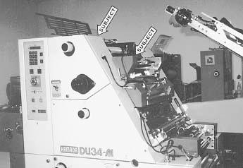
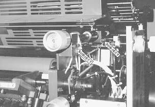
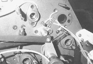
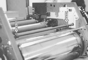
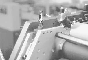
7 DISASSEMBLY 1 Disconnect and remove plate inserter from DU34 parent, right hand subject arrow. 2 Remove side covers at OPS & NOPS, left hand subject arrow, in picture from step 1. Also, remove top inker guard and dampener/ plate cylinder guard as well as their hinges. Save for reinstallation. 3 Remove molleton rollers and water pan from existing dampener. Also, remove small rider roller from top of the first ink form. 7


8 8
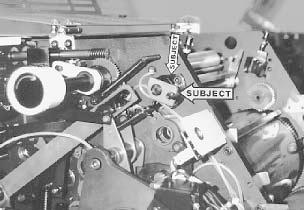
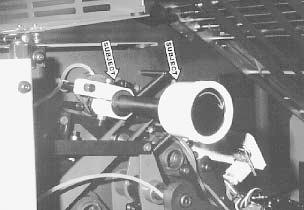
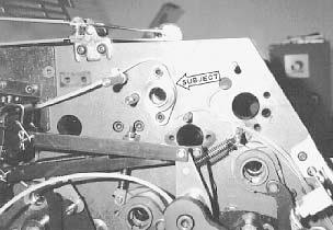
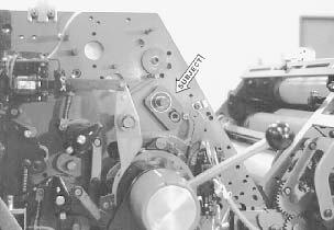
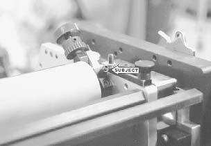
9 DISASSEMBLY 4 At OPS, remove water oscillator drive by punching out roll pin and guide pin, then remove cap screws (subject arrow). 5 Remove oscillator guide spool and drive at NOPS by punching out roll and guide pins and removing cap screws (subject arrow). 6 Optional! Remove oscillator drive link at NOPS (subject arrow). 9
10 10
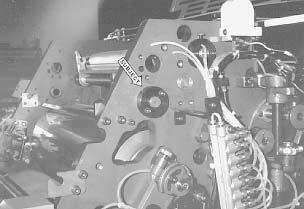
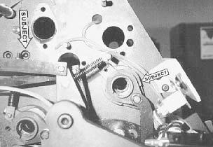
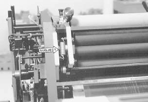
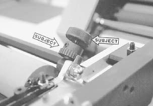
11 DISASSEMBLY 7 Remove water form drive gear from NOPS (subject arrow). 8 Remove pan roller bearing housing at NOPS, loosen screw holding pan roller to journal at OPS and remove pan roller (subject arrow). 9 At OPS, remove water adjustment knob by removing cap screws and guide blocks at OPS (subject arrows). 11

12 12
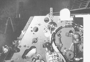
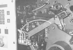
13 DISASSEMBLY 10 Remove knob from end of pan roller journal at OPS (right hand subject arrow). Remove "E" ring, loosen tension block and pull off (left hand subject arrow). Remove second "E" ring, push shaft in and remove from press. 11 At OPS, remove water pan roller drive arm by removing "E" ring at pivot point (left hand subject arrow). The arm is behind the ink fountain roller drive arm. After removing arm, insert the provided spacer in its place and reconnect the ink fountain roller drive arm. 12 Remove water ductor connecting link at OPS (subject arrow) by removing nut and stud at bottom of link, loosening set screw in top of link and pulling out pin. 13
14 14
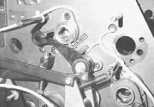
15 DISASSEMBLY 13 Remove link attached to ductor shaft at OPS (subject arrow) by loosening set screw and pushing shaft in. 14 At OPS, loosen set collar on ductor shaft, knock out roll pin in center of the shaft, pull shaft out of the press towards NOPS (subject arrow). After shaft is out, removing bushing at OPS. 15 Remove pan roller bushing at OPS (subject arrow). 15
16 16
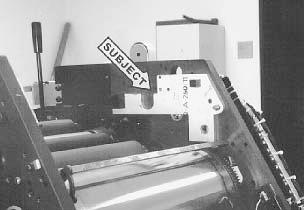
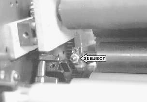
17 DISASSEMBLY 16 At OPS, disconnect water form roller connecting link and remove water form roller housing (right subject arrow). Link remains on press. Remove the tie bar bolt (left subject arrow) and tie bar from the press. You are now ready to install Crestline 17

18 18
19 INSTALLATION 1 Install mounting frames at OPS & NOPS as shown (subject arrow) by placing the pin mounted to the frame in the hole that housed the pan roller. 2 Secure the frame to the press with the provided m5 & m6 socket cap head screws. The m6 bolt uses a flanged spool through the press frame to secure it in place (subject arrow). Bolts installed from the outside of the press frame at OPS & NOPS. 3 Insert actuation shaft halfway through the press frame, undercut on the shaft to the OPS. 19
20 20
21 INSTALLATION 4 Slide lift cams on shaft and align the threads in the cam with the dimples on the shaft. Make sure both cams are facing the same direction with the flats pointing towards the floor (subject arrow). 5 Slide the shaft all the way through the press and install a washer and snap ring on shaft at NOPS. 6 Install support block on actuating shaft and secure with an m8 screw (subject arrow). 21


22 22
23 INSTALLATION 7 Pull the shaft all the way to the OPS and install washer and snap ring at OPS. This sets the side to side position. 8 Slide control block on shaft and attach to existing water form link using m6 screw and spool (subject arrow). Do not tighten set screw in control block. Final position of the cams is set later. 9 Drop dampener in place with the bearings on the end of the pivot studs fitting into the pockets on the mounting brackets. Attach bearing caps to mounting bracket. Note: the set screw in the center of the cap has been preset at factory. Do not adjust. Be sure that the bridge roller on the dampener is disengaged. 23

24 24
25 INSTALLATION 10 Attach springs from stud on mounting frame to stud on dampener frame (subject arrow). 11 Position the lift cams as follows: 1. Place single lever in "Water On" position. 2. Rotate shaft so flats are pointing up, just under, but not touching the lift bearings on the dampener frame (subject arrow). 3. Holding this position, tighten set screw in control block into the undercut groove in lift shaft. 4. Return single lever to "Water Off" position. Cams should rotate up and lift the dampener off the plate cylinder. 12 Install new press tie bar using m5 socket cap screws and washers (subject arrow). M5 Cap screws goes through a tapped m6 hole that is being used as a through hole. 25


26 26
27 INSTALLATION 13 Install water pan and route water hose as illustrated. 14 Install new guard in press as shown using original guard hardware and mounting brackets (subject arrow). 15 If the press is equipped with a satellite unit, remove the small guard attached to the original Hamada cylinder guard. Using the original hardware, reattach the small guard to the Accel dampener/cylinder guard. Originally, the hinges lined up with holes towards the outside edge of the guards (see illustration). However, Hamada has recently moved the hinges towards the center of the guard. 27
28 28
29 INSTALLATION 16 In order to accomodate both the old and new versions, additional holes have been added to the Accel dampener/cylinder guard. The guard has eight holes in it. Simply line up the proper hole positions with the small hinged guard from Hamada. 29

30 30
31 FINAL ADJUSTMENTS 1 Mount a metal plate to the plate cylinder With the single lever in the "Off" position, adjust the amount of lift of the water form off the plate. Lift is adjusted by changing the position of the eccentric cams on the dampener frame (subject arrow). Adjust each eccentric until there is an even.050 gap between the plate and form roller. 2 Dab ink on the dampener on a hard roller and turn the press by hand at first to distribute the ink. Slowly jog and run the press until the ink is distributed evenly on all the dampener rollers. P B M I F 3 Water Form to Plate Drop the water form roller to the plate and check the stripe. It should be 5/32" (4mm). Adjust the stripe using the stop screws on the dampener frame (subject arrow). Turning the screw down decreases the stripe. Lock in place using lock nut. 5/32" (4mm) PLATE CYLINDER 31
32 32
33 FINAL ADJUSTMENTS O B M I F 4 1/8" - 5/32" (3.5-4mm) Metering to Intermediate Check the stripe between the metering and intermediate rollers by dropping the water form to the plate and rotating the press backwards. (Clutches prevent dampener from turning backwards with the water form off the plate. Dropping the form to the plate allows the ink to drive the unit backwards.) PLATE CYLINDER Stripe should be 1/8" - 5/32" (3.5mm - 4mm). Adjust by turning the screw on top of the hanger (subject arrow). Turning the screw down increases the stripe. Tighten lock nut when finished. 5 Intermediate to Form This pressure is set automatically when setting the metering to intermediate in set 4 above. 3/16" (5mm) P B M I F PLATE CYLINDER 6 Metering to Pan Jog the press forward and observe the stripe on the pan roller. It should be 3/16" (4.5mm - 5mm). Turn the knurled metering knobs (right subject arrow) clockwise to increase the stripe. When the proper stripe has been obtained, spin the ratchet gears (left subject arrow) down until they bottom out on the stud and secure the ratchet gear to the knurled knobs with the set screws. 33

34 34
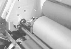
35 FINAL ADJUSTMENTS 1/8" (2.5mm) O B M I F 7 Bridge to Water Form Adjust the pressure by turning the adjusting screw (subject arrow) on the bridge roller cap. Turning the screw in increases the stripe. The stripe should be no more than 1/8" (2.5 mm) and even all the way across the roller. Overpressuring the roller can cause the oscillating mechanism to fail. Lock in place with lock nut. PLATE CYLINDER The bridge roller is intended to make inking and washing up the dampener easier. See sections entitled "Start of Day" and "Wash Ups During The Day". The bridge should not be used during normal operation of the press. 8 Adjust water level in pan by raising or lowering the original water bottle mechanism. 35
36 BASIC OPERATION START OF DAY A. Make sure all the rollers are in place. B. Spin knurled knobs until the ratchet stops. C. Mount plate to cylinder. Wipe down all plates before running. Pre-ink the Crestline dampener before running the plates with an extremely light coverage of ink by engaging the bridge roller. Bridge roller engages by rotating the levers at the OPS & NOPS towards the delivery end of the press, dropping the bridge onto the ink form roller. Disengage by pulling back on the levers until bearing on bridge roller drops into detent. D. Place water bottle in bracket. NOTE: Accel recommends using the proper fountain solution for the plate material being run on the press. A good acid/gum etch should be used with metal plates. RUNNING DURING THE DAY A. In general, the Crestline should not have to be adjusted from job to job. The form roller setting should never be changed unless it has deviated from the factory specification of 5/32" (4mm) to the plate. B. Adjustments to the amount of water fed to the plate are made by the knurled knobs that apply pressure to the metering roller. The dampener has been set up for minimum water. To increase the water to the plate, turn the knurled knobs counter clockwise 1 or 2 clicks at a time. This opens the gap between the metering and pan rollers and allows more water to the plate. C. In general, more water will only be required when going from a metal plate to an electrostatic or Silvermaster type plate. 36
37 CLEANING & MAINTENANCE WASH UPS DURING THE DAY 1. Remove bottle and drain the excess water from the pan. 2. Mount a metal plate to the press. 3. Turn on the press and squirt a small amount of press wash on the ink rollers. 4. Engage the bridge roller by rotating the levers at the OPS & NOPS towards the delivery end of the press, dropping the bridge onto the ink form roller. 5. Use wash up attachment as normal. When the press is clean disengage bridge roller by pulling back on the levers until bearing on bridge roller drops into detent. 6. Remove water pan and clean any solution left in it. 7. Be sure to wipe excess clean up solution from the ends of the dampener metering and pan rollers. END OF THE DAY 1. Wash up press. Pay close attention to cleaning the ends of the pan and metering rollers that extend past the form rollers. 2. Spin the knurled knobs up until the metering roller can be removed. 3. Remove metering roller and wipe down thoroughly to remove any excess wash that may be on the roller. 37
38 CLEANING & MAINTENANCE DEGLAZING THE DAMPENER If you are running electrostatic masters on a daily basis, the dampener should be deglazed at least once a week with Accel's Compound X, deep cleaner and deglazer. If using other plate materials, this should be done every 2-4 weeks. ACCEL RECOMMENDS AVOIDING DEGLAZERS CONTAIN- ING PUMICE OR GRITTY SUBSTANCES. Avoid washes that are extremely fast drying. Crestline 's form and pan rollers are made of relatively soft rubber and should not be subjected to harsh, fast drying washers, especially those containing acetone. Fast drying washes should be used for blankets only! OILING AND GREASING THE DAMPENER A. Place a small amount of grease on the gears once a month. B. Inject grease into the oscillator grease fitting once a month. 38
39 CLEANING & MAINTENANCE CRESTLINE CLEANING & MAINTENANCE CHART Daily Weekly Bi-Weekly Monthly Wash Rollers Deglaze Rollers Metal Plate Users Silvermaster Plate Users Electrostatic Plate Users Grease Gears Inspect Ball Bearings Check Roller Pressures Check Roller Surfaces 39
40 40
41 41
42 42
43 43
44 44
45 45
46 46
47 47
48 48
49 49
50 50
51 51
52 52
53 53
54 54
55 55
56 56
57
58 11103 Indian Trail, Dallas, TX Phone , Fax Web Site
Crestline Dampening System. Installation Instructions. Ryobi 2700, 2800, 3200, 3200E Itek 950, 960, 975 Parent. X /98 Rev-A
 Crestline Dampening System Installation Instructions Ryobi 2700, 2800, 3200, 3200E Itek 950, 960, 975 Parent X88-30 3/98 Rev-A GENERAL INFORMATION ATTENTION CRESTLINE DAMPENER OWNER! Accel Graphic Systems
Crestline Dampening System. Installation Instructions. 4 ROLL DAMPENER Ryobi 3302M Itek 3985 A.B. Dick 9985 X /98
 Crestline Dampening System Installation Instructions 4 ROLL DAMPENER Ryobi 3302M Itek 3985 A.B. Dick 9985 X88-49 1/98 GENERAL INFORMATION ATTENTION CRESTLINE DAMPENER OWNER! Accel Graphic Systems provides
Crestline Dampening System. Installation Instructions. Shinohara 66. X /98 Rev-A 2598
 Crestline Dampening System Installation Instructions Shinohara 66 X88-58 8/98 Rev-A 2598 GENERAL INFORMATION ATTENTION CRESTLINE DAMPENER OWNER! Accel Graphic Systems provides parts and service through
Replacing the Reciprocator on an SWF Multi-head.
 Replacing the Reciprocator on an SWF Multi-head. Follow the instructions below to replace the reciprocator in the SWF multi-head machines. The tools required are found in the tool kit that came with the
Inventory MODEL T10096 TAPER ATTACHMENT FOR G0509 & G0509G LATHE INSTRUCTIONS. Inventory (Figure 1) Needed Items
 Needed Items") MODEL T10096 TAPER ATTACHMENT FOR G0509 & G0509G LATHE INSTRUCTIONS Inventory The Model T10096 taper attachment was carefully packed when it left our warehouse. If you discover it is damaged after you
MODEL T10096 TAPER ATTACHMENT FOR G0509 & G0509G LATHE INSTRUCTIONS Inventory The Model T10096 taper attachment was carefully packed when it left our warehouse. If you discover it is damaged after you
INSTALLATION GUIDE 2009-CURRENT HUMMER H3T PRODUCT CODE:
 INSTALLATION GUIDE 2009-CURRENT HUMMER H3T PRODUCT CODE: 268 June 22, 2010 TOOLS NEEDED COMPONENTS INCLUDED P2 Tip 3/8" Drill Rubber Gasket(s) x 2 Bracket(s) x 2 1/2" Drill Bit Bulkhead Flange #2 Phillips
EXIT DEVICE OPERATION FIRE DOOR LABELS, STRIKES AND FRAME SCREWS FOR INFORMATION CALL OR VISIT RITEDOOR.COM
 RECORD & LABELS WHAT THIS OWNER'S CAN DO FOR YOU It explains exactly how The Rite Door operates. It explains periodic maintenance requirements necessary to assure reliable operation. It explains simple
Installation Instructions
 The IMS ETERNAL FIX PATENT PENDING Installation Instructions EPS recommends professional installation for the Eternal IMS Fix. Please take all precautionary safety measures. We also recommend putting the
Preference Collection and Treatment Console INSTALLATION GUIDE
 Preference Collection 5580.69 and 5580.96 Treatment Console INSTALLATION GUIDE WARNING Failure to install the 5580 as described in this installation guide may cause the unit to collapse, resulting in serious
Electric Skein Winder
 Electric Skein Winder Assembly and Use Package Contents 1 - Triangular Body (w/ motor) 1 - Cross Arm 1 - Left Foot (w/ yarn guide) 1 - Right Foot 1 - Adjustable Finger (w/ yarn clip) 3 - Adjustable Fingers
Preference Collection 5580 Treatment Console INSTALLATION GUIDE
 Preference Collection 5580 Treatment Console INSTALLATION GUIDE 0 WARNING Failure to install the 5580 as described in this installation guide may cause the unit to collapse, resulting in serious injury
HYDRAULIC CONTROL DETAILS PARTS LIST
 Always give model number, serial number and part number when ordering repair parts. HYDRAULIC CONTROL DETAILS PARTS LIST REF NO. PART NUMBER DESCRIPTION 1 101939 Hydraulic Tank 2 101940 Hydraulic Tank
Daily Maintenance. 2. Insert bobbin cases in to rotary hooks. Make sure bobbin thread is not over 2 inches long. Close bobbin case covers.
 Rotary hook 1. Open bobbin case covers and remove bobbin cases. Use brush to remove lint build up in and around rotary hooks. Compressed air may also be used. Daily Maintenance Cle aning Oiling Rotary
RTI TECHNOLOGIES, INC.
 RTI TECHNOLOGIES, INC. BRC500 & BRC550 Arbor/Spindle Mechanism Adjustment & Service Technical Instructions The arbor/spindle mechanism of the BRC500/550 is designed to be robust for long life. Occasionally
Replacing the build plate clamps
 Repair manual Replacing the build plate clamps Instructions The build plate clamps hold the glass plate in place on the heated bed. There are two fixed in place at the back of the heated bed and two at
Installation and Assembly - Universal Articulating Swivel Double-Arm for 42" - 60" Plasma Screens
 Installation and Assembly - Universal Articulating Swivel Double-Arm for 42" - 60" Plasma Screens Models: PLAV 70-UNL, PLAV 70-UNL-S PLAV 70-UNLP, PLAV 70-UNLP-S R This product is UL Listed. It must be
N. 15th Street, Middlesboro, KY FLIP TARP DUMP BODY INSTALLATION INSTRUCTIONS
 1-800-248-7717 1002 N. 15th Street, Middlesboro, KY 40965 FLIP TARP DUMP BODY INSTALLATION INSTRUCTIONS Congratulations on your purchase of a Mountain Flip Tarp Dump Body tarping system. With tarping systems
Inventory MODEL H7937 TAPER ATTACHMENT FOR THE G0600 LATHE INSTRUCTIONS. Inventory (Figure 1) Needed Items
 Needed Items") MODEL H7937 TAPER ATTACHMENT FOR THE G0600 LATHE INSTRUCTIONS Inventory The Model H7937 taper attachment was carefully packed when it left our warehouse. If you discover it is damaged after you have signed
MODEL H7937 TAPER ATTACHMENT FOR THE G0600 LATHE INSTRUCTIONS Inventory The Model H7937 taper attachment was carefully packed when it left our warehouse. If you discover it is damaged after you have signed
SERVICE MANUAL AND PARTSLIST
 SERVICE MANUAL AND PARTSLIST Next 20 CONTENTS WHAT TO DO WHEN... 1~3 SERVICE ACCESS FACE COVER... 4 TOP COVER... 4 BASE COVER... 5 REAR COVER... 6 FRONT COVER... 7 MECHANICAL ADJUSTMENT NEEDLE THREAD TENSION...
H8508 Impact Wrench SERVICE MANUAL. Model (Serial Code FWN) Model (Serial Code FWP)
 Model (Serial Code FWP)") SERVICE MANUAL H8508 Impact Wrench Model 48755 (Serial Code FWN) Model 48760 (Serial Code FWP) Read and understand all of the instructions and safety information in this manual before operating or servicing
SERVICE MANUAL H8508 Impact Wrench Model 48755 (Serial Code FWN) Model 48760 (Serial Code FWP) Read and understand all of the instructions and safety information in this manual before operating or servicing
Gared Pro-S Portable Backstop
 Models: 9616 & 9618 Installation, Operation and Maintenance Instructions Please read all instructions before attempting installation or operation of these units SAVE THESE INSTRUCTIONS FOR FUTURE USE PUBLICATION
SERVICE PARTS LIST PAGE 1 OF 6 BASE ASSEMBLY SPECIFY CATALOG NO. AND SERIAL NO. WHEN ORDERING PARTS 12" SLIDING COMPOUND MITER SAW
 PAGE 1 OF 6 BASE ASSEMBLY 00 0 CATALOG NO. EXAMPLE: SPECIFY CATALOG NO. AND NO. WHEN ORDERING PARTS 6955-20 1 02-80-0050 Thrust Bearing (1) 2 05-80-0510 M5 x 12mm Flat Head T-20 Screw (5) 3 05-81-0135
HD38, HD58, HD78 REV
 HD38, HD58, HD78 REV. 07.29.2014 COVER for HD38, HD58, HD78 5 P004868 1/4-20x3/4 Button Head Cap Screw Stainless Steel 2 6 P001450 Lockwasher - Internal Tooth.250 6 8 P005200 Wave Disc Washer 4 10 P004869
Installation and Assembly: In-wall Mount for 32" to 71" Flat Panel Screens
 Installation and Assembly: In-wall Mount for 32" to 71" Flat Panel Screens Model# IM760P, IM760P-S IM760PU, IM760PU-S Screen size range 32" to 71" (81 to 180 cm) 32" to 60" (81 to 152 cm) IM760P IM760P-S
DYNATRAC BALL JOINT REBUILD INSTRUCTIONS V4.0
 DYNATRAC PRODUCTS 2007-2016 4X4 JEEP JK HEAVY DUTY BALL JOINT JP44-2X3050-C DYNATRAC BALL JOINT REBUILD INSTRUCTIONS V4.0 WARNING: Improper use or installation of this product can cause major failures
SUPER PRO GUN & SUPER PRO GUN II
 MAGNUM VENUS PRODUCTS Maintenance & Repair Manual Part No. M6707-1-1 Revision 04.14.01 Maintenance & Repair Corporate HQ & Mfg. Phone: (727) 573-2955 Fax: (727) 571-3636 Email: info@magind.com Web: www.magind.com
Cam Handle Service Guide
 Cam Handle Service Guide Page 2. Introduction Page 3. Troubleshooting guide Page 4-5. Adjusting the clamp force Page 6-7. Disassembling, greasing and replacing components Page 8-9. Replacing the post bearings
MS25 OPERATION MANUAL
 SAFETY INSTRUCTIONS SPECIFICATIONS OPERATING INSTRUCTIONS MAINTENANCE ADJUSTMENTS REPLACEMENT OF PARTS MS25 DIAGRAM MS25 PARTS LIST MS25 OPERATION MANUAL SAFETY INSTRUCTIONS Please read these instructions
REPLACEMENT TARP for SRT-2 SPOOL ROLL TARP
 REPLACEMENT TARP for SRT-2 SPOOL ROLL TARP NOTICE TO INSTALLER: Even if familiar with product, read instructions prior to installation as improvements may be made without notice. Always handle components
Parts list Instruction guide Warnings Please read carefully before assembling and using product.
 Parts list Instruction guide Warnings Please read carefully before assembling and using product. Jet Rail XL Part Number 27377 Tools required for assembly Hammer 9/16 Wrench 3/4 Wrench Ratchet 9/16 Socket
Installation and Assembly: In-wall Mount for 32" to 71" Flat Panel Displays
 Installation and Assembly: In-wall Mount for 32" to 71" Flat Panel Displays Model# Display size range IM760P, IM760P-S 32" to 71" (81 to 180 cm) IM760PU, IM760PU-S 32" to 65" (81 to 165 cm) This product
PROSTEER BALL JOINT REBUILD INSTRUCTIONS V1.0
 DYNATRAC PRODUCTS 2003-2010 4X4 DODGE 2500/3500 HEAVY DUTY BALL JOINT PROSTEER BALL JOINT REBUILD INSTRUCTIONS V1.0 WARNING: Improper use or installation of this product can cause major failures that could
Inventory (Figure 2)
") MODEL T10127 12" SPIRAL CUTTERHEAD INSTRUCTIONS The Model T10127 indexable insert spiral cutterhead is designed to replace the straightknife cutterhead from the Grizzly jointer Model G0609. The total procedure
MODEL T10127 12" SPIRAL CUTTERHEAD INSTRUCTIONS The Model T10127 indexable insert spiral cutterhead is designed to replace the straightknife cutterhead from the Grizzly jointer Model G0609. The total procedure
INSTALLATION GUIDE. Model:B60 RECESSED IN WALL MOUNT
 INSTALLATION GUIDE Model:B60 RECESSED IN WALL MOUNT Features: Installs between 16 (406mm) wood stud centers Mounting Pattern Compliance: VESA 100*100mm up to 600 x 400mm Level 5 degree horizontal adjustment
M14 MODULAR CHASSIS SYSTEM (MOD 1) INSTRUCTION MANUAL. West Springfield, MA Phone: (866) FAX: (413)
 INSTRUCTION MANUAL. West Springfield, MA Phone: (866) FAX: (413)") M14 MODULAR CHASSIS SYSTEM (MOD 1) INSTRUCTION MANUAL Troy Industries, Inc. WWW.TROYIND.COM West Springfield, MA 01089 Phone: (866) 788-6412 FAX: (413) 383-0339 Thank You M14/M1A MODULAR CHASSIS SYSTEM
M14 MODULAR CHASSIS SYSTEM (MOD 1) INSTRUCTION MANUAL Troy Industries, Inc. WWW.TROYIND.COM West Springfield, MA 01089 Phone: (866) 788-6412 FAX: (413) 383-0339 Thank You M14/M1A MODULAR CHASSIS SYSTEM
DO35 MAINTENANCE INSTRUCTIONS
 CUSTOMER INFORMATION SHEET NO. 038 DO35 MAINTENANCE INSTRUCTIONS (DO35 V3 LAUNCHED PRODUCTION JUNE 2017) Table of Contents 1.0 Replacing Spindle Bushes V3... 22 2.0 Replacing Locking Mechanism V3... 6
Preference Collection 5543 Central Console INSTALLATION GUIDE
 Preference Collection 5543 Central Console INSTALLATION GUIDE WARNING Failure to install the 5543 as described in this installation guide may cause the unit to collapse, resulting in serious injury to
M14 MODULAR CHASSIS SYSTEM (MOD 1) INSTRUCTION MANUAL. West Springfield, MA Phone: (866) FAX: (413)
 INSTRUCTION MANUAL. West Springfield, MA Phone: (866) FAX: (413)") M14 MODULAR CHASSIS SYSTEM (MOD 1) INSTRUCTION MANUAL Troy Industries, Inc. WWW.TROYIND.COM West Springfield, MA 01089 Phone: (866) 788-6412 FAX: (413) 383-0339 Thank You M14/M1A MODULAR CHASSIS SYSTEM
M14 MODULAR CHASSIS SYSTEM (MOD 1) INSTRUCTION MANUAL Troy Industries, Inc. WWW.TROYIND.COM West Springfield, MA 01089 Phone: (866) 788-6412 FAX: (413) 383-0339 Thank You M14/M1A MODULAR CHASSIS SYSTEM
MOTORIZED STANDARD SHADE WITH CABLES Installation Instructions
 Tools Needed Drill Measuring Tape Pencil 2 Level Plumb Line ¼ Masonry Drill Bit Hammer Linesmans Pliers Cable Cutters Phillips & Flat-Head Screw Driver 11/32 Socket or Open End Wrench 5/32 Allen Wrench
TorqueMaster Replacement Spring
 TorqueMaster Replacement Spring Installation Instructions NOTE: Use these installation instructions in conjunction with the TorqueMaster Repair / Replacement Spring Program literature. Copyright 999 Wayne-Dalton
Model: SCD430 SCD640. Installation & Operation Guide P/N SCD640-95
 Model: SCD430 SCD640 Installation & Operation Guide P/N SCD640-95 Model SCD430 and SCD640 Kurt has two Self-Centering vises, a four-inch jaw width (SCD430) and a six-inch jaw width (SCD640). Jaw opening
APS Small Seeds Box Assembly Instructions
 APS Small Seeds Box Assembly Instructions For APS15 Series All Purpose Seeder Manual No. 313-473M Before You Start! When you see this symbol, the subsequent instructions and warnings are serious - follow
PFW 6875 Installation Guide Installationsanleitung, Guía de Instalacíon, Guida de Installazione, Guide d Installation, Installatie gids
 Maximum Flat Panel Weight: 160 lb. / 72.57 kg. Included Components Wall Mount (Qty 1) Extension Brackets (Qty 2) Bracket (Qty 1 Pair) 5/16 Flat Washers (Qty 4) Universal Spacers (Qty 8) M5 Allen Driver
Fortress Fe Posts must always be secured to the deck framing. Fortress Fe Posts should never be attached to only the deck boards.
 Installation Instructions for FortressCable H-Series Stair Panels with Simplified Stair Bracket SSB-05 and Fe Posts It is the responsibility of the installer to meet all code and safety requirements, and
Maintenance Information
 16601023 Edition 2 January 2014 Air Impact Wrench 2705P1 Maintenance Information Save These Instructions Product Safety Information WARNING Failure to observe the following warnings, and to avoid these
Installation and Assembly - Universal Articulating Swivel Double-Arm for 42" - 60" Plasma Screens
 Installation and Assembly - Universal Articulating Swivel Double-Arm for 42" - 60" Plasma Screens Models: PLAV 70-UNL, PLAV 70-UNL-S PLAV 70-UNLP, PLAV 70-UNLP-S R This product is UL Listed. It must be
RYOBI. 10 in. (254 mm) TABLE SAW MODEL NO. BTS15 REPAIR SHEET
 TABLE SAW MODEL NO. BTS15 REPAIR SHEET") RYOBI 0 in. ( mm) TABLE SAW MODEL NO. BTS REPAIR SHEET FIGURE A 0 0 0 0 The model number will be found on a plate attached to the motor housing. Always mention the model number in all correspondence regarding
RYOBI 0 in. ( mm) TABLE SAW MODEL NO. BTS REPAIR SHEET FIGURE A 0 0 0 0 The model number will be found on a plate attached to the motor housing. Always mention the model number in all correspondence regarding
Installing the Partridge RA Extension on Losmandy G11
 Installing the Partridge RA Extension on Losmandy G11 Michael Herman July 20, 2015 Tools: 3/16 inch hex key (allen wrench) [If desired for DEC indicator ring friction improvement: flat screwdriver, and
ABM International, Inc.
 ABM International, Inc. Lightning Stitch required 1 1.0: Parts List head and motor assembly (Qty. 1) Reel stand (Qty. 1) Needle bar frame clamp (Qty. 1) Motor drive (Qty. 1) 2 Cable harness with bracket
SECTION 9: PARTS. Headstock A 126A 127A-1 REF PART # DESCRIPTION REF PART # DESCRIPTION
 SECTION 9: PARTS Headstock 120 121 113 115 112 111 110 109 108 105 106 107 135 101 119A 121 120 118 114 115 107 106 104 123 122 118 114 126A 105 126 103 102 126B 127A-1 131 127A 124 133 134 126C 129 130
SERVICE PARTS LIST PAGE 1 OF 6 BASE ASSEMBLY SPECIFY CATALOG NO. AND SERIAL NO. WHEN ORDERING PARTS 12" DUAL BEVEL COMPOUND MITER SAW B27B
 PAGE 1 OF 6 BASE ASSEMBLY 00 0 EXAMPLE: Component Parts (Small #) Are Included When Ordering The Assembly (Large #). SPECIFY CATALOG NO. AND NO. WHEN ORDERING PARTS = Part number change from previous service
25000 Series Lo-T TM Butterfly Control Valve Instructions
 November 2001 25000 Series Lo-T TM Butterfly Control Valve Instructions Instruction No. 25.1:IM PRELIMINARY STEPS Before installation, note the flow direction arrow on the valve body. The flow should enter
PHG-1000X. Owner s Manual HOME GYM
 HOME GYM Owner s Manual WWW.BODYSOLID.COM THERE IS A RISK ASSUMED BY INDIVIDUALS WHO USE THIS TYPE OF EQUIPMENT. TO MINIMIZE RISK, YOU MUST FOLLOW THESE RULES:! " # $ % & ' ( ) * + ' (, ' " -. *, * ) )
RULTRACT RETRACTOR CABLE REPLACEMENT INSTRUCTIONS. Rultract, Inc. is the ONLY authorized service center in the U.S.A.
 RULTRACT RETRACTOR CABLE REPLACEMENT INSTRUCTIONS Rultract, Inc. is the ONLY authorized service center in the U.S.A. When your Rultract instrument needs repair or service, contact Rultract Inc. or Rultract
RZ 200 Parts Diagram. To avoid confusion during installation remove this page and router being installed pages, return others to box.
 Collar Page 1 To avoid confusion during installation remove this page and router being installed pages, return others to box. Caution: Before and during installation of Router Raizer make sure power switch
General Features. Low Profile. The SMART BOXX stands only 1.5 off of the bed of your truck so cargo space is maximized
 General Features Low Profile. The SMART BOXX stands only 1.5 off of the bed of your truck so cargo space is maximized Two Sizes Short Box :74 L X 47 W X 7 T and Long Box 92 L X 47 W X 7 T All Aluminium
MODEL H " BYRD SHELIX CUTTERHEAD INSTRUCTIONS
 MODEL H9291 12" BYRD SHELIX CUTTERHEAD INSTRUCTIONS The Model H9291 12" Byrd Shelix cutterhead is designed to replace the straight-knife cutterhead on the Grizzly jointer Model G0609. The total procedure
FACTORY CAT TOMCAT CORPORATION
 FACTORY CAT RPS TOMCAT CORPORATION Artificial Turf and Carpet Sweeping Install Kit #349-641 & #349-642 1. Detach batteries so that there is no power running through the machine before starting. 2. Start
400A 40113V, 401A 40120V, & 401AL 40120VL ALUMINUM VERTICAL 4000 LB LIFT INCLUDES SCREW LEG ASSEMBLY INSTRUCTIONS
 12/11/07 PAGE 1 OF 12 400A 40113V, 401A 40120V, & 401AL 40120VL ALUMINUM VERTICAL 4000 LB LIFT INCLUDES SCREW LEG ASSEMBLY INSTRUCTIONS Thank you for purchasing our product! *Please read these instructions
CV1B Sliding Table Installation and Setup Guide
 CV1B Sliding Table Installation and Setup Guide Tech Mark, Inc 7901 Industry Drive North Little Rock, AR 72117 tel (501) 945-9393 fax (501) 945-0312 www.tech-mark.com email: info@tech-mark.com The CV1B
LEG CURL IP-S1315 INSTALLATION INSTRUCTIONS
 LEG CURL IP-S35 INSTALLATION INSTRUCTIONS Copyright 2009. Star Trac by Unisen, Inc. All rights reserved, including those to reproduce this book or parts thereof in any form without first obtaining written
Side Winder R o u t e r L i f t.
 Woodpeckers PRECISION WOODWORKING TOOLS Side Winder R o u t e r L i f t. INSTALLATION INSTRUCTIONS The wrench handle must be pointing left in order to fully insert or remove it. Lift Wrench Once fully
TRUE TECHNICAL SERVICE MANUAL - ALL MODELS. DOORS/DRAWERS/LIDS
 DOORS/DRAWERS/LIDS 55 56 NOTES DOORS/DRAWERS/LIDS Springs 97 TORSION SPRING REPLACEMENT GDM RADIUS FRONT - SWING DOOR INSTALLATION INSTRUCTIONS Tools Required (2) - 1 8" drift Punch (forged) Needle-Nose
Replacing the Reciprocator on the SWF Compact Series Machine (601C and 1201C)
") Follow the instructions below to replace the reciprocator in the SWF Compact series machines. The tools required can be found in the tool kit that came with the machine. Preparation 1. First, place the
Follow the instructions below to replace the reciprocator in the SWF Compact series machines. The tools required can be found in the tool kit that came with the machine. Preparation 1. First, place the
The Bowflex Revolution XP Home Gym Assembly Instructions. P/N: Rev ( /0 )
") P/N: 001-7057 Rev ( /0 ) The Bowflex Revolution XP Home Gym Assembly Instructions 2 Table of Contents Before You Start... 2 Tools You Will Need / Hardware Contents... 3 Box Contents... 6 Assembling Your
P/N: 001-7057 Rev ( /0 ) The Bowflex Revolution XP Home Gym Assembly Instructions 2 Table of Contents Before You Start... 2 Tools You Will Need / Hardware Contents... 3 Box Contents... 6 Assembling Your
3.2.3 Rear Door Window and Quarter Window Carrier Assembly
 Tighten all bolts. Tighten bolts marked -1- and -2- in specified sequence. Tightening torque: 8 Nm Remaining bolts can be tightened in any sequence. Insert door window -3- through window recess without
FLIP TARP SINGLE & DOUBLE UNDERBODY TRAILERS
 1-800-248-7717 1002 N. 15th Street, Middlesboro, KY 40965 FLIP TARP SINGLE & DOUBLE UNDERBODY TRAILERS INSTALLATION INSTRUCTIONS Congratulations on your purchase of a Mountain Flip Tarp Trailer system.
Click Here to Go Back
 Click Here to Go Back Fig. -94 Fig. -97 CC42D 10. Remove the cap screw securing the gear shift stopper plate pin retainer; then remove the retainer. Fig. -95 CC45D 12. Remove the link arm and account for
CORVETTE CORVETTE REV: Made in USA U.S. PATENT #6,808,223; #6,845,547; #7,140,075; #7,059,655 and other patents pending.
 CORVETTE 2005-2006 CORVETTE 2005-2007 REV: 7-2-07 Made in USA U.S. PATENT #6,808,223; #6,845,547; #7,140,075; #7,059,655 and other patents pending. Page 1 of 12 CORVETTE C6 2005-2007 THIS KIT INCLUDES:
Pantry IMPORTANT NOTE Carefully remove all the parts from the carton and put them individually on a soft cloth to prevent scratches or oth
 88 5076 691 Pantry IMPORTANT NOTE Carefully remove all the parts from the carton and put them individually on a soft cloth to prevent scratches or other damages occurring to the parts. We have taken great
SINGER 531B-8BL. From the library of: Superior Sewing Machine & Supply LLC
 SINGER 53B-8BL PERSPECTIVE THREAD TENSION, GUIDE, NEEDLE PLATE i SINGER 4 THREAD TENSION, GUIDE, NEEDLE PLATE 3 Fig. No. Parts No. Quantity Name of Parts Fig. No. Parts No. Quantity Name of Parts 0698
Astro-Physics Inc. 400QMD Lubrication/Maintenance Guide
 Astro-Physics Inc. 400QMD Lubrication/Maintenance Guide The following guidelines should be followed to lubricate the three main parts of the 400QMD mount. The QMD stands for Quartz Micro-Drive controller.
GlideRite Retractable Cover System For Hot Spot Spas (SE & SLX only)
") List of Contents Quantity Description 12 #10 x 1 ½ Flat Head Phillips Screw (see pg. 2) 2 #10 x ½ Pan Head Phillips Screw (see pg. 2) 8 ¼ x 2 ½ Lag Bolt (see pg. 2) 7 ¼ 20 x 5 / 8 Hex Head Bolt (see pg.
List of Contents Quantity Description 12 #10 x 1 ½ Flat Head Phillips Screw (see pg. 2) 2 #10 x ½ Pan Head Phillips Screw (see pg. 2) 8 ¼ x 2 ½ Lag Bolt (see pg. 2) 7 ¼ 20 x 5 / 8 Hex Head Bolt (see pg.
OPERATIONAL MANUAL V1.0. Removing/Replacing Blades
 OPERATIONAL MANUAL V1.0 BLUEROCK WS-212 Wire Stripper Removing/Replacing Blades CAUTION!! IMPORTANT!! DANGER!! WARNING!! DISCONNECT MACHINE FROM POWER BEFORE PROCEEDING!! Estimated Completion Time: 90
Sentinel Series Cigar Humidor End Tables
 Sentinel Series Cigar Humidor End Tables Assembly Instructions Models: Sentinel 500, 1000 and 1500 Style: Traditional SENTINEL ASSEMBLY INSTRUCTIONS Congratulations! You have purchased a superior cigar
EPPA2-KIT DUAL MONITOR ARM CONVERSION
 EPPA2-KIT DUAL MONITOR ARM CONVERSION EPPA2-KIT Rev A 10/17 Model EPPA2-KIT-XXX ASSEMBLY AND ADJUSTMENT EPPA2-KIT PARTS AND TOOLS PLEASE REVIEW these instructions before beginning the assembly and adjustment
EZ-Lock Assembly Manual
 ABM International, Inc. EZ-Lock Assembly Manual 1 ABM International, Inc. Series: 1018/1022/1026 V1.0 EZ-Lock Parts List - Structural frame profiles Slotted beam: (Qty. 2) 15.75 Commercial Parts - Liner
STOP. V00029AC Rev. 04 READ ALL OF THE FOLLOWING INSTRUCTIONS BEFORE REMOVING CABINET FROM SKID TOOL LIST. NET-ACCESS S-Type Network Cabinets
 Rev. 04 STOP READ ALL OF THE FOLLOWING INSTRUCTIONS BEFORE REMOVING CABINET FROM SKID NET-ACCESS S-Type Network Cabinets -Phillips screwdriver -Flatblade screwdriver -22mm socket wrench -15mm socket wrench
6625 WEST WILSHIRE BLVD. OKLAHOMA CITY, OK (405) FAX (405)
 FAX (405)") INSTALLATION INSTRUCTIONS FOR THE TAILGATE WITH LATCH AND LINK ASSEMBLY 76-87 FORD SHORT & 53-87 FORD LONG FLARESIDES 1. Assemble the bed and make sure the box is square. Measure the distance between the
INSTALLATION INSTRUCTIONS FOR THE TAILGATE WITH LATCH AND LINK ASSEMBLY 76-87 FORD SHORT & 53-87 FORD LONG FLARESIDES 1. Assemble the bed and make sure the box is square. Measure the distance between the
LPK1550 Hydraulic Crimping Tool 15-ton
 SERVICE MANUAL LPK1550 Hydraulic Crimping Tool 15-ton Serial Code FYF Read and understand all of the instructions and safety information in this manual before operating or servicing this tool. Register
REPAIR INSTRUCTIONS: CABLE
 The repair instructions describe replacing the Cable in the Easy Sun PARASOL Sunshade. These repair instructions are intended only for persons with experience of using the tools required. Please read the
3D PRINTER. Pack 11. Anything you can imagine, you can make! 3D technology is now available for you at home! BUILD YOUR OWN
 BUILD YOUR OWN Pack 11 Anything you can imagine, you can make! 3D PRINTER Compatible with Windows 7 & 8 Mac OS X 3D technology is now available for you at home! BUILD YOUR OWN 3D PRINTER CONTENTS PACK
MPA-9000 Universal Ceiling Projector Mount Kit
 I N S T R U C T I O N M A N U A L Universal Ceiling Projector Mount Kit The Universal Ceiling Projector Mount provides a unique, simplified method of ceiling mounting your inverted projector. This low
DYNATRAC BALL JOINT REBUILD INSTRUCTIONS V5.0
 DYNATRAC PRODUCTS 2007-2018 JEEP JK HEAVY DUTY BALL JOINT JP44-2X3050-C DYNATRAC BALL JOINT REBUILD INSTRUCTIONS V5.0 WARNING: Improper use or installation of this product can cause major failures that
Service Manual. 600 Series Box Frame Steering Shaft and Segment Gear Servicing
 Service Manual 600 Series Box Frame (These procedures are appropriate for box frame tractors produced after November 2002) IMPORTANT: READ SAFETY RULES AND INSTRUCTIONS CAREFULLY This Service Manual is
GlideRite Retractable Cover System For HotSpring & Tiger River Spas (except Classic & pre-2000 Landmark Spas)
") List of Contents Quantity Description 12 #10 x 1 ½ Flat Head Phillips Screw (see pg. 2) 2 #10 x ½ Pan Head Phillips Screw (see pg. 2) 8 ¼ x 2 ½ Lag Bolt (see pg. 2) 7 ¼ 20 x 5 / 8 Hex Head Bolt (see pg.
List of Contents Quantity Description 12 #10 x 1 ½ Flat Head Phillips Screw (see pg. 2) 2 #10 x ½ Pan Head Phillips Screw (see pg. 2) 8 ¼ x 2 ½ Lag Bolt (see pg. 2) 7 ¼ 20 x 5 / 8 Hex Head Bolt (see pg.
Motorized M3 AX7200 Rotary-Style Gasket Cutter Operating Instructions
 Motorized M3 AX7200 Rotary-Style Gasket Cutter Operating Instructions INTRODUCTION Congratulations! You are the owner of the finest rotary-style gasket cutter in the world. Originally developed and patented
Fortress Fe Posts must always be secured to the deck framing. Fortress Fe Posts should never be attached to only the deck boards.
 Installation Instructions for Fortress Horizontal Cable Panel System with UB-05 Brackets and Fe Posts It is the responsibility of the installer to meet all code and safety requirements, and to obtain all
PFW Installation Guide Installationsanleitung, Guía de Instalacíon, Guida de Installazione, Guide d Installation, Installatie gids
 Maximum Flat Panel Weight: 100 lb. / 45.35 kg. Included Components Wall Mount (Qty 1) Extension Bracket (Qty 1 Pair) Bracket (Qty 1 Pair) 5/16 Flat Washers (Qty 4) Universal Spacers (Qty 8) M5 Allen Driver
MODELS 49 RA 49 RAZ 49 RAC
 General Safety and Maintenance Manual MODEL grinder featuring a rear exhaust. Model Number Exhaust Direction REAR Throttle Type (L) Lever or (K) Safety Lever Speed 12000 to 14000 R.P.M (13500rpm is standard)
STENCIL MACHINE OPERATION uline.com H-259, H-347 H-408 CUTTING THE OIL BOARD INSERTING THE OIL BOARD
 H-259, H-347 H-408 π STENCIL MACHINE 1-800-295-5510 uline.com OPERATION NOTE: No assembly is necessary after you unpack your machine. INSERTING THE OIL BOARD 1. Move the release lever to the right. This
MOTOR & BULK HEAD. A Manual for Repair and Maintenance Technicians
 MOTOR & BULK HEAD A Manual for Repair and Maintenance Technicians CAUTION This manual is designed to help technicians who are already experienced in workshop procedures and know how to handle tools. Only
3/8-16 x 3/4 cap screw. 3/8-16 hex nut for above screws. 1/4-20 x 3/4 socket cap screw. 3/16 short arm hex key (not to scale)
") Super Slab Roller 24, 30 and 36 models Worktable Assembly Directions P.O. Box 89 Cheney, WA 99004 USA 509.235.9200/800.23.7896 Fax: 509.235.9203 www.northstarequipment.com Revised September, 2006. All
Super Slab Roller 24, 30 and 36 models Worktable Assembly Directions P.O. Box 89 Cheney, WA 99004 USA 509.235.9200/800.23.7896 Fax: 509.235.9203 www.northstarequipment.com Revised September, 2006. All
IMPORTANT! Recommended Tools. 7/16 Deep socket Phillips screwdriver
 IMPORTANT! Read all instructions carefully before commencing any work. Always wear proper safety equipment. Some installation steps will require two or more installers. Recommended Tools Ratchet 10-mm
Arc Trainer Main Frame Assembly
 Arc Trainer Main Frame Assembly Kit No. 610AK019-4 Kit No. 630AK019-4 NOTE: This instruction sheet describes how to replace the main frame assembly in the Arc Trainer 610A. Tools Required 3/16 Allen wrench
Queen Wingback Bed King Wingback Bed
 Parts and Hardware List A. Side Rails with Attachment Hooks 2 pcs B. Foot Rail 1 pc C. Head Rail 1 pc D. Center Support Slat 1 pc E. Leg Supports 3 pcs F. Support Slats 4 pcs G. Flat Washers 8 pcs H. Lock
OPERATING INSTRUCTIONS 3421UX VETERANS BLVD, CARLSTADT, NJ 07072
 OPERATING INSTRUCTIONS 3421UX5-1 400 VETERANS BLVD, CARLSTADT, NJ 07072 CONTENTS DESCRIPTION... 3 OPERATOR INFORMATION... 5-8 INSTALLATION...... 4 ADJUSTMENT... 8-17 LUBRICATION... 5 INDEX Description
OTECO INC. MODEL ,000 PSI 4-1/16 PORT DM GATE VALVE MAINTENANCE MANUAL
 Page 1 of 7 OTECO INC. MODEL 45 4 5,000 PSI 4-1/16 PORT DM GATE VALVE MAINTENANCE MANUAL Page 2 of 7 TABLE OF CONTENTS 1. Assembly Blowout 2. Repair Kit Contents & Technical Specifications 3. Disassembly
Removing Right-Side. Components. Right-Side. Components. Click Here to Go Back AT THIS POINT
 Click Here to Go Back NOTE: There is an oil passage beneath the driven gear/drive gear assembly. This passage should be plugged prior to removing the driven gear and drive gear. Failure to do so could
Display-Top Apothecary Cabinet. Assembly Instructions. Page 1
 Display-Top Apothecary Cabinet Assembly Instructions Page 1 Display-Top Apothecary Cabinet Parts List Please check packaging for all parts and hardware before discarding. Unpack and lay parts on clean,