TO OPERATE AUTO-GUIDE POWER. 24 Gauge Pittsburgh Operating Instructions FLANGING ATTACHMENT
|
|
|
- Blanche Ross
- 5 years ago
- Views:
Transcription
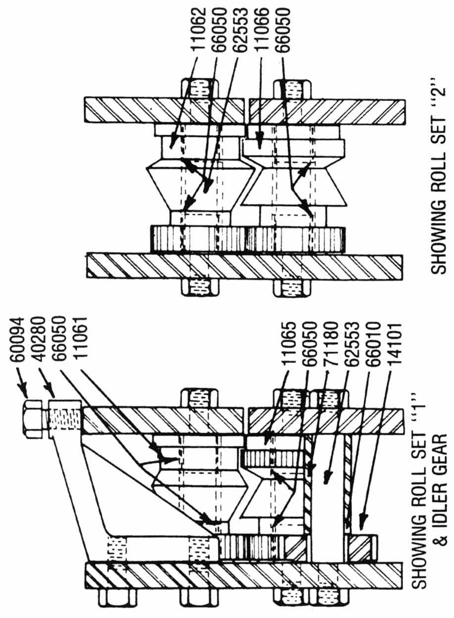
1 24 Gauge Pittsburgh Operating Instructions Holding the material against the angle gauge slide it into the forming head. Be sure that the material remains against the gauge until work is finished. Make "Hold-Down Adjustment" to meet any variation in the material of your locality. Do not adjust unless material slips, tends to leave gauge, or curls up at finish. If the material slips, tighten the studs equally until the condition is overcome. It is very important that long sheets be fed into the machine flat and against the gauge for the start. IMPORTANT: If proper care is taken, the small knife edge roll that holds the pocket of the Pittsburgh Lock open will not break. If burrs and twists from snip cuts are not flattened out, it will sometimes strike against the opening roll causing it to break. SPECIFICATIONS GENERAL: Recess for Pittsburgh Lock Flange is 5/16 deep... Hammer-over edge adjustable for width... Uses about 7/8 of material... One piece Pittsburgh lock rolls, gears and shafts... FORMING UNIT: Hardened and ground steel shafts, precision made case hardened steel forming rolls, machine cut gears... CAPACITY. 24 gauge and lighter MOTOR: Standard equipment V3 H.P., V, 60 cycle, single phase, A.C., plugs into regular light socket (other types available) DRIVE: single V belt... STAND: arc-welded steel construction finished in blue machinery enamel, heavy top plate DIMENSIONS: 30 long, 14 wide, 16 ½ high overall including Power Flanger, 12 high without flanger, cabinet height 8 WEIGHT: 150 lbs. ROLLER BEARINGS THROUGHOUT. Power Flanger makes ¼ Right Angle Flange on either straight or curved pieces to a radius as small as 1 ¾. It is fitted with an adjustable guide which can be set to hold metal to the gauge and automatically turn a flange to a given radius or a straight line. TO OPERATE AUTO-GUIDE POWER FLANGING ATTACHMENT ADJUST UNIT FOR GAUGE To adjust clearance between flanging MATERIAL TO BE USED rolls, tighten the adjusting screw on the front of the block of the machine all the way, then loosen the screw approximately one eighth of a turn. (This setting is usually correct for 26 gauge material.) Do not set front gauge adjusting screw too tight. It should be set just tight enough to draw the metal through the rolls. Too tight a setting will stretch and wrinkle the material. To adjust the spring tension on the compensator arm, tighten the adjusting dial on the back side of the flanger to the stop and then turn back to the proper gauge setting shown on the adjusting dial. TURN UP A "STARTING FLANGE" on the material before inserting it into the rolls. This is done by inserting the leading edge of the work to be flanged in the slot cut into the table and bending the piece away from the operator approximately 45º. Start the leading edge of the material into the rolls. As the material posses through the rolls, the compensator arm will make contact with the material and guide it through the rolls. If the material pulls out of the rolls, it is on indication that either the front adjusting screw is too loose or the back adjusting dial is not tight enough. IMPORTANT. When starting ci partially formed section that contains an inside curve, push the compensator arm back until it locks out of position. Feed partially formed section into the rolls and the machine will pull the material through. As the rolls approach the section that is not formed, bring the compensator arm to the material holding the spring tension off the piece until the unformed section comes to the rolls; then bear pressure to the piece until the flange picks up, then release compensator arm so that "automatic" guiding is resumed. Lubrication The slow speed shafts do not require lubrication. Check oil in motor occasionally. If machine is used out of doors an oil or grease film will prevent rusting of surfaces. TO INSTALL AUTO-GUIDE POWER FLANGING ATTACHMENT 1. Remove top cover from Lockformer by removing the two hold-down studs and lifting the cover from the machine. 2. Replace the two hold-down studs and adjust. 3. Set the flanging attachment over the forming head so that the combination bevel and spur gear meshes with the Pittsburgh Lock roll No Place the two 3/8" x 1 1/4" Hex-Head cap screws and lock washers into flanging attachment mounting holes and tighten.
2 24 GAUGE PITTSBURGH MACHINE PARTS LIST AND DESCRIPTION Part Number Description Pieces Per Unit Part Number Description Pieces Per Unit Back Housing Plate Lower Front Housing Plate UpperFront Housing Plate Feed Gauge Bar Bottom Forming Roll B Bottom Forming Roll B Bottom Forming Roll B Bottom Forming Roll B Bottom Forming Roll B Top Forming Roll T4 & T Top Forming Roll T Top Forming Roll T Top Forming Roll T lst Drive Shaft w/integral Gear nd Drive Shaft w/integral Gear Gear Driven with Hub Sheave Machine 9-1/ Opening Roll Hldr Assembly Machine Support Bracket Cast Bearing B1012 Torr Bearing B128 Torr Opening Roll Bearing B812 Torr Bearing B108 Torr /16-18 x 1/2 HHCS Spacer Spacer Step Thrust Collar Idler Gear (need 1 (6601 c)) #9 Woodruff Key Upper Idler Roll (need ) Lower Idler Roll (need ) Idler Roll Pin /8-16 x 1-1/4 HHCS FT /16-18 x 3/4 HHCS Spacer Stud Stand Assembly Toggle Switch Cover Assembly A5 23 5/8 Sheave /16-18 x 5/16 SSS /16-18 HN Heavy SF /8-16 x 3/8 SSS /4-20 x 1/4 SSS /8-16 Jam Nut SF /8-24 Lck. Nut Cord 14-3 x 10 Ft L 500 Belt /3 HP BX Connector 1/ /16-18 x 3/4 FHMS /16 Lck. Washer /16 Drive Screw U Cad Lf. Cap Name Plate /4 x.031 Brs. Washer /8-16 x 1 HHCS /16 x 1/16 Stl. Washer /8 Lock Washer Sta. Kon Connector Bl Insulating Cap Wire Joint Toggle Switch Plate Lockformer Logo 1
3
4
5

6
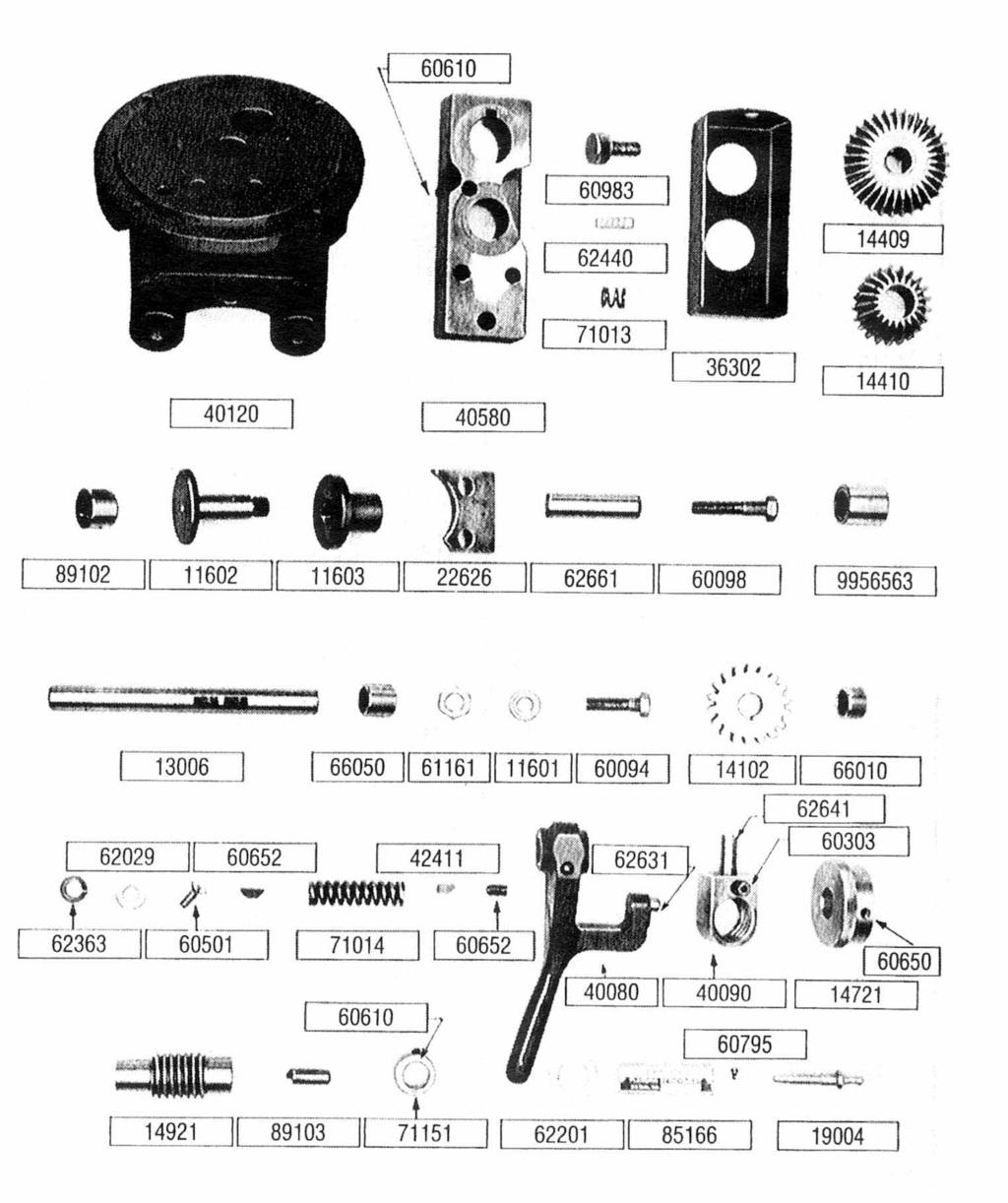
7 24 GAUGE FLANGING ATTACHMENT PARTS LIST AND DESCRIPTION Part Number Description Pieces Per Unit Cast Iron Base Steel Forming Head Special Machine Key Concave Compression Spring 3/8 ID Cover Gear Bevel Gear Comb. Spur & Bevel Lifter Plug Knurled Forming Roll Plain Forming Roll Spacer Plate /8 x 2-1/4 Dowell Pin /8-16 x 2 HHCS Inner Race Assembly Roll Shaft Bearing B /2-20 NF Hex. Nut Adjustable Guide Roll /8-16 x 1-1 /4 HHCS Gear Gearing B108 Torr /8 Lock Washer /4-20 x 112 FHMS / 16 Sq. x 1-1 / 2 Key /16-18 x 1/2 SSS Dowel Pin 3/8 x 3/ /4-20 x 114 Set Screw Woodruff Key Modified Compensator Arm Tension Screw Nut Gauge Dial Tension Screw Tension Spring Push Rod /16 x 1-1/2 Dowel Pin Spring Compression Sensory Casting /8 Collar Washer 518 x 1/ /4-20 x 3/4 SHCS Name Plate x 3/16 Drive Screw Forming Table /8-16 x 1 STS /8 x 1/16 Washer Removable Cover Bearing 1
8
24 GA. PITTS ROLLFORMER
 1 TIN KNOCKER 24 GA. PITTS ROLLFORMER INSTRUCTIONS & PARTS DIAGRAM Shown with Stand and Optional Flanging Attachment Rev. 092606 TAAG MACHINERY CO. (Master Distributor) 1257-B Activity Dr. Vista, CA 92081
Operating Instructions
 Operating Instructions Holding the material against the angle gauge slide it into the forming head. Be sure that the material remains against the gauge until work is finished. NOTE: This machine will handle
Operating Instructions For Lockformer Button Punch Flanger
 Capacity: 20 to 28 Gauge Galvanize Operating Instructions For Lockformer Button Punch Flanger To satisfactorily form the 90º button punch flange on light gauge materials, it was necessary to form the metal
No. 412, 414, 416 Operations Manual
 No. 412, 414, 416 Operations Manual CARE: Occasional oiling of moving parts with machine oil will ease operation and extend the life of the brake. Occasionally check and tighten the lower beam bracket
Lockformer / 16 Gauge Speednotch
 Lockformer / 16 Gauge Speednotch INSTALLATION PRELIMINARY: After uncrating, locate unit, with or without base skid, to area of operation. Unbind foot switch cord and cylinder hoses and remove gauge pin
INSTRUCTION MANUAL AND PARTS LIST MODEL 14-10
 VERTICAL BAND SAWS INSTRUCTION MANUAL AND PARTS LIST MODEL 1-10 DAKE/PARMA WHEN ORDERING PARTS GIVE COMPLETE SERIAL NUMBER OF MACHINE GIVE PART NUMBER AND NAME GIVE AMOUNT REQUIRED Unless the above data
MODEL 36 Di-Acro Hand Shear
 OPERATOR S MANUAL & INSTRUCTIONS MODEL 36 Di-Acro Hand Shear Di-Acro, Incorporated PO Box 9700 Canton, Ohio 44711 3713 Progress Street N.E. Canton, Ohio 44705 330-455-1942 330-455-0220 (fax) Revised 01/02
ITEM NO. PART NO DESCRIPTION QTY.
 PUMP MAINTENANCE ITEM NO. PART NO DESCRIPTION QTY. 1 52002 Center Case 1 2 52052 Back End Plate 1 3 52051 Front End Plate 1 4 55090 Octagonal Nut 1 5 53001 Idler Gear 1 6 53002 Drive Gear 1 7 28062 Bushing
OPERATION & MAINTENANCE MANUAL
 OPERATION & MAINTENANCE MANUAL AUTOMATIC PECAN CRACKER Food Processing Equipment and Machinery Specializing in the Pecan Industry Mailing: PO Box 817, Mansfield, Louisiana 71052 Located: 280 Independence
G0513X2 Main -87- G0513 Series Bandsaws 82V V2 82-6V2 95A V2 82-5V2 82-1V2 82-4V V A
 G0513X2 Main 23 55 22 48 17 17-1 17-2 21 7 17-3 17-2 17-4 24 17-5 18-5 22 24 21 55A 50 8 9 49 11 12 13 14 15 47 16 10 46 45 3 44 43 39 38 37 39 40 32 33 36 42 34 35 2 25 28 18-4 18-2 18-3 31 30 29 18-1
HYDRAULIC CONTROL DETAILS PARTS LIST
 Always give model number, serial number and part number when ordering repair parts. HYDRAULIC CONTROL DETAILS PARTS LIST REF NO. PART NUMBER DESCRIPTION 1 101939 Hydraulic Tank 2 101940 Hydraulic Tank
SERVICE MANUAL AND PARTSLIST
 SERVICE MANUAL AND PARTSLIST Next 20 CONTENTS WHAT TO DO WHEN... 1~3 SERVICE ACCESS FACE COVER... 4 TOP COVER... 4 BASE COVER... 5 REAR COVER... 6 FRONT COVER... 7 MECHANICAL ADJUSTMENT NEEDLE THREAD TENSION...
Operating Instructions and Parts Manual 10-inch Table Saw
 Operating Instructions and Parts Manual 10-inch Table Saw Model 66 shown with optional extension table and legs, mobile base, and motor cover WMH TOOL GROUP 2420 Vantage Drive Elgin, Illinois 60123 Part
Astro-Physics Inc. 400QMD Lubrication/Maintenance Guide
 Astro-Physics Inc. 400QMD Lubrication/Maintenance Guide The following guidelines should be followed to lubricate the three main parts of the 400QMD mount. The QMD stands for Quartz Micro-Drive controller.
AndyMark DART 12.
 AndyMark DART 12 Part Number Description QTY These Parts Are Pre-Assembled by AndyMark am-0031 Bearing, 3/16"ID (R3) 1 am-0209 Bearing, 3/8"ID 1614ZZ 2 am-1028 Screw, #10-32x3/8 Pan Head Philips 8 am-1121
Parts Catalog. S-Series Slicer Manual Frozen Option S13. Model:
 , 07 995 ECN 08 Parts Catalog S S-Series Slicer Manual Frozen Option Model: S 05/0/07 Rev. G IMPORTANT! TO EXPEDITE SHIPMENT OF PARTS, ALWAYS SPECIFY MODEL, REV, PART NUMBER, AND SERIAL NUMBER OF UNIT.
General Four-Way Operation, Maintenance & Service Manual
 General Four-Way Operation, Maintenance & Service Manual SCOPE Included in the following pages you will find assembly drawings, exploded views, parts lists, assembly tips, operational descriptions and
G0513X2 Main. G0513 Series Bandsaws (Mfd. Since 07/18) A V2
 A V2") G0513X2 Main 55 17 48 7 16 55A 14 15 49 13 47 50 12 10 71 70 72 73 59 69 74 46 11 9 8 76 5 75 4 68 81 80 67 66 48 50 39 78 79 23 17-3 17-2 17-1 17-4 17-2 21 22 24 17-5 32 33 34 35 28 2 45 3 38 44 39 43
G0513X2 Main 55 17 48 7 16 55A 14 15 49 13 47 50 12 10 71 70 72 73 59 69 74 46 11 9 8 76 5 75 4 68 81 80 67 66 48 50 39 78 79 23 17-3 17-2 17-1 17-4 17-2 21 22 24 17-5 32 33 34 35 28 2 45 3 38 44 39 43
SERVICE MANUAL PARTS LIST MODEL: NH40
 SERVICE MANUAL & PARTS LIST MODEL: NH40 CONTENTS What to do when... 1-3 SERVICE ACCESS Face Cover... 4 Bed Cover... 5 Free-arm Cover... 6 Front Cover... 7 Rear Cover... 8 MECHANICAL ADJUSTMENT Presser
Number Wheeler P/N Description Set Rex P/N Notes Base 1 J Support, Right 1 J Support, Left 1 J Nut (M8)
") 1 603500 Base 1 J001 2 603501 Support, Right 1 J002 3 603502 Support, Left 1 J003 4 600328 Nut (M8) 4 5 600130 Spring Washer (8mm) 4 6 600344 Roll Pin (M6x30) 4 7 600129 Socket Hd Cap Screw (M8x25) 4 8
1 603500 Base 1 J001 2 603501 Support, Right 1 J002 3 603502 Support, Left 1 J003 4 600328 Nut (M8) 4 5 600130 Spring Washer (8mm) 4 6 600344 Roll Pin (M6x30) 4 7 600129 Socket Hd Cap Screw (M8x25) 4 8
Tire Chain Kit. Replacing Shear Pins. Weight Kits. Drift Cutter
 Replacing Shear Pins The augers are secured to the spiral shaft with two shear pins and cotter pins. If the auger should strike a foreign object or ice jam, the snow thrower is designed so that the pins
SECTION 9: PARTS. Headstock A 126A 127A-1 REF PART # DESCRIPTION REF PART # DESCRIPTION
 SECTION 9: PARTS Headstock 120 121 113 115 112 111 110 109 108 105 106 107 135 101 119A 121 120 118 114 115 107 106 104 123 122 118 114 126A 105 126 103 102 126B 127A-1 131 127A 124 133 134 126C 129 130
M2 Assembly. M2 Sub-Assemblies mm Belt Sub-Assembly mm Belt Sub-Assembly Spider Sub-Assembly... 4
 M2 Assembly Table of Contents M2 Sub-Assemblies... 3 630mm Belt Sub-Assembly... 3 702mm Belt Sub-Assembly... 3 Spider Sub-Assembly... 4 Idler Bolt Sub-Assembly... 8 Y Motor Sub-Assembly... 9 X Motor Sub-Assembly...
CATALOG OF REPLACEMENT PARTS
 The Choice of Experience CATALOG OF REPLACEMENT PARTS MODELS 909A 919A 909E 919E 909M 919M SLICERS EFFECTIVE MARCH 2009 - 2 - Table of Contents 5 ELECTRICAL COMPONENTS (909A & 919A) 7 ELECTRICAL COMPONENTS
Hydraulic Clamp Carrier. Installation & Operation Manual
 Hydraulic Clamp Carrier Installation & Operation Manual Hydraulic Clamp Carrier Installation & Operation Manual Quick Machinery Company 8272 Peninsula Drive Kelseyville, CA 95451 phone: (707) 272-6719
LS2-B891 LT2-B892 LS2-B891-05, LT2-B892-05
 LS2-B891 LT2-B892 Single Needle Unison Feed Lock Stitcher Single Needle Unison Feed Lock Stitcher with Thread Trimmer Twin Needle Unison Feed Lock Stitcher Twin Needle Unison Feed Lock Stitcher with Thread
REPAIR INSTRUCTIONS. Cat. No Cat. No MILWAUKEE ELECTRIC TOOL CORPORATION. SDS Max Demolition Hammer. SDS Max Rotary Hammer
 Cat. No. 9-0 SDS Max Demolition Hammer Cat. No. -0 SDS Max Rotary Hammer MILWAUKEE ELECTRIC TOOL CORPORATION W. LISBON ROAD BROOKFIELD, WISCONSIN 00-0 8-9-0 d 000 8-9-0 d Special Tools Require Forcing
Parts Catalog. S-Series Slicer Smart Manual SG13. Model:
 , 07 99507 ECN 065 Parts Catalog S-Series Slicer Smart Manual Model: SG SG 0/0/07 Rev. G IMPORTANT! TO EXPEDITE SHIPMENT OF PARTS, ALWAYS SPECIFY MODEL, REV, PART NUMBER, AND SERIAL NUMBER OF UNIT. GLOBE
RYOBI 10 in. TABLE SAW - MODEL NO. BT3000
 FOR MITER TABLE ASSEMBLY, REFER TO FIGURE 0 RYOBI 0 in. TABLE SAW - MODEL NO. BT000 FIGURE 5: 0 in. TABLE SAW FOR BLADE GUARD ASSEMBLY, REFER TO FIGURE FOR RIP FENCE ASSEMBLY, REFER TO FIGURE FOR MOTOR
RYOBI 10 IN (254 MM) TABLE SAW MODEL NO. BT REPAIR SHEET
 TABLE SAW MODEL NO. BT REPAIR SHEET") RYOBI 0 IN (2 MM) TABLE SAW MODEL NO. BT00- REPAIR SHEET 2 RYOBI 0 in. (2 mm) TABLE SAW - MODEL NO. BT00- FOR MITER TABLE ASSEMBLY, REFER TO FIGURE B FOR BLADE GUARD ASSEMBLY, REFER TO FIGURE E FOR RIP
RYOBI 0 IN (2 MM) TABLE SAW MODEL NO. BT00- REPAIR SHEET 2 RYOBI 0 in. (2 mm) TABLE SAW - MODEL NO. BT00- FOR MITER TABLE ASSEMBLY, REFER TO FIGURE B FOR BLADE GUARD ASSEMBLY, REFER TO FIGURE E FOR RIP
D('00 D]^ ('&'. G8IKJ
![D('00 D]^ ('&'. G8IKJ](/thumbs/90/103707123.jpg "D('00 D]^ ('&'. G8IKJ") 1 2 5 6 7 8 11 12 10 13 14 15 27 28 16 26 29 30 25 17 19 20 22 21 32 23 24 31 42 43 33 34 40 41 35 49 36 37 51 52 53 44 45 46 47 38 39 48 18-40- 1 XM1099001 CONTROL PANEL FACE 29 XPCAP50M CAP SCREW M5-.8
1 2 5 6 7 8 11 12 10 13 14 15 27 28 16 26 29 30 25 17 19 20 22 21 32 23 24 31 42 43 33 34 40 41 35 49 36 37 51 52 53 44 45 46 47 38 39 48 18-40- 1 XM1099001 CONTROL PANEL FACE 29 XPCAP50M CAP SCREW M5-.8
Motorized M3 AX7200 Rotary-Style Gasket Cutter Operating Instructions
 Motorized M3 AX7200 Rotary-Style Gasket Cutter Operating Instructions INTRODUCTION Congratulations! You are the owner of the finest rotary-style gasket cutter in the world. Originally developed and patented
Operating Instructions and Parts Manual 5-ft. Radial Arm Drill Press Models J-1600R, J-1600R-4
 Operating Instructions and Parts Manual 5-ft. Radial Arm Drill Press Models J-1600R, J-1600R-4 JET 427 New Sanford Road LaVergne, Tennessee 37086 Part No. M-320038 Ph.: 800-274-6848 Revision H 01/2016
SECTION 9: PARTS Main
 SECTION 9: PARTS Main 58 63 67 66 65 67 66 59 58 49 58 48 49 61A 61 64 62 55 50 35-3 34 35-1 57 56 41 42 151 51 50 33A 35-2 30A 30A-1 35 38 39 31 32 18 40 43 44 68 51 41 45 46 57 56 55 47 152 153 20 21
Figure 1A. Solid Waste Can / Glass Shredder Assembly
 Figure A. Solid Waste Can / Glass Shredder Assembly Figure B. Solid Waste Mod Plastics Shredder Assembly Solid Waste Can / Glass Shredder & Solid Waste Mod. I Plastics Shredder Assemblies FIG. INDEX PART
INSTRUCTIONS AND PARTS LIST POWER HAMMER
 INSTRUCTIONS AND PARTS LIST POWER HAMMER DAKE (Division of JSJ) 724 Robbins Road Grand Haven, Michigan 49417 616.842.7110 Phone 800-937-3253 616.842.0859 Fax 800-846-3253 Web: www.dakecorp.com E-mail :
CATALOG OF REPLACEMENT PARTS
 CATALOG OF REPLACEMENT PARTS 3000 SERIES AUTOMATIC SLICERS 3713 ML-136144 3713 (Canada) ML-136177 3713N ML-136181 3713N (Canada) ML-136184 3913 ML-136145 3913 (Canada) ML-136179 3913N ML-136183 3913N (Canada)
JARVIS. Model BR-3 Blade Reconditioner ... EQUIPMENT TABLE OF
 - Model BR-3 Blade Reconditioner EQUIPMENT SELECTION.......... Ordering No. TABLE OF CONTENTS............................ Page Model BR-3 (100 mm Blade) 115V/60Hz............ 4011003 220V/50Hz............
3000, 4000, 4100, 7500, 7700
 3000, 4000, 4100, 7500, 7700 Drum & Disc Brake Lathes s Identification READ these instructions before placing unit in service. KEEP these and other materials delivered with the unit in a binder near the
Wheeler Rex Ashtabula, Ohio Tel: Fax:
 Wheeler Rex Ashtabula, Ohio Tel: 800 321 7950 Fax: 440 992 2925 wheeler@wheelerrex.com www.wheelerrex.com December 2012 There are three different types of shell cutters. Nominal Hole Size Part No. 4" 3395
PARTS G9729 Lathe Bed
 PARTS G9729 Lathe Bed 114 132 126 125 131 133 129 128 130 127 139 124 10 124 123 122 135 137 147 144 121 148 146 149 136 138 140 150 152 142 143 141 151 153 21 168 20 19 18 17 162 22 147 13315 14 13131
C70 Window Roller Repair Taken from: Heres the problem:
 C70 Window Roller Repair Taken from: http://www.volvospeed.com/vs_forum/topic/115086-how-to-c70-window-rollers-permanent-fix/ Heres the problem: This happened to two separate window assemblys on my c70
RYOBI 10 in. (254 mm) TABLE SAW MODEL NO. BT3100 REPAIR SHEET
 TABLE SAW MODEL NO. BT3100 REPAIR SHEET") RYOBI 0 in. (4 mm) TABLE SAW MODEL NO. BT00 REPAIR SHEET FOR MITER TABLE ASSEMBLY, REFER TO FIGURE B FOR BLADE GUARD ASSEMBLY, REFER TO FIGURE E FOR RIP FENCE ASSEMBLY, REFER TO FIGURE C FOR MOTOR ASSEMBLY,
RYOBI 0 in. (4 mm) TABLE SAW MODEL NO. BT00 REPAIR SHEET FOR MITER TABLE ASSEMBLY, REFER TO FIGURE B FOR BLADE GUARD ASSEMBLY, REFER TO FIGURE E FOR RIP FENCE ASSEMBLY, REFER TO FIGURE C FOR MOTOR ASSEMBLY,
SERVICE PARTS LIST PAGE 1 OF 6 BASE ASSEMBLY SPECIFY CATALOG NO. AND SERIAL NO. WHEN ORDERING PARTS 12" SLIDING COMPOUND MITER SAW
 PAGE 1 OF 6 BASE ASSEMBLY 00 0 CATALOG NO. EXAMPLE: SPECIFY CATALOG NO. AND NO. WHEN ORDERING PARTS 6955-20 1 02-80-0050 Thrust Bearing (1) 2 05-80-0510 M5 x 12mm Flat Head T-20 Screw (5) 3 05-81-0135
HD installation guide
 JANUS INTERNATIONAL 1 866 562 2580 www.janusintl.c o m 1950 1950HD installation guide RIGHT DRIVE END SHOWN LH OPPOSITE LEFT TENSION END SHOWN RH OPPOSITE PUSH-UP OPERATION 1950 1950HD SHOWN A rolling
HANDWHEEL ASSEMBLY UPGRADE
 HANDWHEEL ASSEMBLY UPGRADE PURPOSE The purpose of the notice is to document the procedures involved in removing old handwheel assembly parts and replacing them with new parts. The new parts allow the handwheel
400A 40113V, 401A 40120V, & 401AL 40120VL ALUMINUM VERTICAL 4000 LB LIFT INCLUDES SCREW LEG ASSEMBLY INSTRUCTIONS
 12/11/07 PAGE 1 OF 12 400A 40113V, 401A 40120V, & 401AL 40120VL ALUMINUM VERTICAL 4000 LB LIFT INCLUDES SCREW LEG ASSEMBLY INSTRUCTIONS Thank you for purchasing our product! *Please read these instructions
RECOMMENDED SPARE PARTS FOR NORMAL ONE (1) YEAR OPERATION OF VD CRUSHER
 YEAR OPERATION OF VD CRUSHER") RECOMMENDED SPARE PARTS FOR NORMAL ONE (1) YEAR OPERATION OF VD CRUSHER 2 ea. VD-65 Toggle 2 ea. VD-70A Right Hand Bearing Split Bushing 2 ea. VD-70B Left Hand Bearing Split Bushing 2 ea. VD-82 Plate for
RECOMMENDED SPARE PARTS FOR NORMAL ONE (1) YEAR OPERATION OF VD CRUSHER 2 ea. VD-65 Toggle 2 ea. VD-70A Right Hand Bearing Split Bushing 2 ea. VD-70B Left Hand Bearing Split Bushing 2 ea. VD-82 Plate for
Di-Acro 36 Power Shear
 OPERATOR S MANUAL & INSTRUCTIONS Di-Acro 36 Power Shear Di-Acro, Incorporated PO Box 9700 Canton, Ohio 44711 3713 Progress Street N.E. Canton, Ohio 44705 330-455-1942 330-455-0220 (fax) Revised 01/02 Sale
th St N Oak Park Heights, MN Phone: Fax:
 12430 55 th St N Oak Park Heights, MN 55082 Phone: 651.342.1756 Fax: 651.342.1293 Email: info@diacro.com SAFETY INFORMATION PG. 3 MAINTENANCE PG. 3 #4 BENDER BREAKDOWN AND PARTS LIST PG. 4-6 QUIK-LOK BREAKDOWN
12. Mechanical Drawings & Parts Breakdown List
 12. Mechanical Drawings & Parts Breakdown List Note: When ordering parts, please be prepared with, 1. Machine model & serial number. 2. Item number. 3. Part number and description. 4. Year of Production.
Square Wheel Belt Grinder Models: 4103, 4106, and 4126AC
 This Manual is Bookmarked Operating Instructions Parts Manual Square Wheel Belt Grinder Models: 4103, 4106, and 4126AC WHM TOOL GROUP 2420 Vantage Drive Elgin, Illinois 60123 Ph.: 800-274-6848 www.wmhtoolgroup.com
Horizontal and Vertical. Metal Cutting Band Saw MODEL: BS-115
 Horizontal and Vertical Metal Cutting Band Saw MODEL: BS-5 SAFETY. Know your band saw. Read the operator s Manual carefully. Learn the operations, applications and limitation.. Use recommended accessories.
STARTING SERIAL NUMBER PARTS LIST FOR. Wellsaw MODEL 600 METAL CUTTING BAND SAW
 STARTING SERIAL NUMBER 11075 PARTS LIST FOR Wellsaw MODEL 600 METAL CUTTING BAND SAW Wellsaw 2829 N. Burdick, Kalamazoo, MI 49004 Phone: 269-345-1132 Fax: 269-345-0095 Rev 171005 INSTALLATION, OPERATION
Headstock PARTS -61- REF PART # DESCRIPTION REF PART # DESCRIPTION
 For Machines Mfg. Since 8/11 Headstock Model SB1001 8K Lathe 3 2 1 43 46 4 5 6 8 7 47 48 49 11 10 11 9 13 12 14 15 16 17 18 19 44 45 42 41 40 39 38 37 36 34 33 32 15 20 21 22 23 24 25 26 27 28 29 30 31
BRAVO STERN DRIVE 3 C BRAVO ONE
 RAVO STERN DRIVE 3 C 22439 RAVO ONE Table of Contents Page Specifications............................... 3C-1 Torque Specifications..................... 3C-1 Preloads................................ 3C-1
H8508 Impact Wrench SERVICE MANUAL. Model (Serial Code FWN) Model (Serial Code FWP)
 Model (Serial Code FWP)") SERVICE MANUAL H8508 Impact Wrench Model 48755 (Serial Code FWN) Model 48760 (Serial Code FWP) Read and understand all of the instructions and safety information in this manual before operating or servicing
SERVICE MANUAL H8508 Impact Wrench Model 48755 (Serial Code FWN) Model 48760 (Serial Code FWP) Read and understand all of the instructions and safety information in this manual before operating or servicing
Bead Roller Operating, Servicing, and Safety Instruction Manual
 Bead Roller Operating, Servicing, and Safety Instruction Manual CAUTION: Read and Understand These Operating, Servicing, and Safety Instructions, Before Using This Machine. 1-800-67-26 10 Cooperative Way
installation guide
 JANUS INTERNATIONAL 1 866 562 2580 w w w. j a n u s i n t l. c o m 2000 2500 3000 installation guide RIGHT DRIVE END SHOWN LH OPPOSITE LEFT TENSION END SHOWN RH OPPOSITE PUSH-UP OPERATION 2000 2500 3000
SERIES I MILLING MACHINES
 INSTALLATION, OPERATION, MAINTENANCE, AND PARTS LIST SERIES I MILLING MACHINES TP5260 Revised: August 29, 2005 Manual No. M-450 Litho in U.S.A. Part No. M -0009500-0450 June, 2003 MAINTENANCE PROCEDURES
Typical Group D Rear Acoustical Cover Installation
 SERIES 60 SERVICE MANUAL 1. Gear Case Cover 5. Bolt 2. Gear Case 6. Acoustical Cover 3. Acoustical Cover Snap 7. Acoustical Cover 4. Acoustical Cover Clip 8. Nut Figure 1-179 Typical Group D Rear Acoustical
W & A PARTS MANUAL STACKER BUSTER LEVEL BANDER. Model No Quality Products from W & A MANUFACTURING COMPANY
 W & A PARTS MANUAL 12 ROW @ 38 STACKER BUSTER LEVEL BANDER Model No. 3668 SPECIALIZED FARM EQUIPMENT Quality Products from W & A MANUFACTURING COMPANY P.O. Box 5238, Pine Bluff, Arkansas 71611 Phone: (870)
25-200H. 12 Planer / Jointer. with Helical Cutterhead. Parts List.
 25-200H 12 Planer / Jointer with Helical Cutterhead 4001824 Parts List www.rikontools.com CABINET ASSEMBLY PARTS EXPLOSION & PARTS LIST KEY NO. DESCRIPTION KEY NO. DESCRIPTION 1 Pan Head Screw M6x12 P25-200H-1
20" WOODTURNING LATHE Model 3520A
 20" WOODTURNING LATHE Model 3520A Instruction Manual & Parts List M-0460221 (800) 248-0144 www.powermatic.com SPECIFICATIONS: 3520A Lathe Table with standard extensions... 28 x 38 Distance Between Centers...
3850, Drum & Disc Brake Lathes. Parts Identification
 3850, 3860 Drum & Disc Brake Lathes Parts Identification READ these instructions before placing unit in service. KEEP these and other materials delivered with the unit in a binder near the machine for
SERVICING MANUAL 419S/423S
 SERVICING MANUAL 415 419S/423S TROUBLESHOOTING PROBLEM CAUSE REMEDY REFERENCE 1. SKIPPING 1. NEEDLE IS NOT INSERTED INSERT THE NEEDLE PROPERLY. STITCHES PROPERLY. 2. NEEDLE IS BENT OR WORN. CHANGE THE
ST1014 PARTS ST1014 Headstock Breakdown
 ST1014 PARTS ST1014 Headstock Breakdown 112 114 23 104 105 108 102 106 20 19 21 22 101 100 103 111 38 14 15 37 46 44 47 45 107 93 39 41 40 67 110 109 74 75 76 11 12 13 9 8 6 10 31-2 31-3 3 2 7 26 24 31-1
6000, Heavy Duty Drum/Disc Lathe. Parts Identification
 6000, 6002 Heavy Duty Drum/Disc Lathe Parts Identification READ these instructions before placing unit in service. KEEP these and other materials delivered with the unit in a binder near the machine for
TURBO DRIVE INSTALLATION MODEL 1582T KNEE FEED Lagun Mill
 TURBO DRIVE INSTALLATION MODEL 1582T KNEE FEED Lagun Mill NOTE This Turbo Drive Knee Feed is configured for mounting the feed on the front of the knee with the keypad facing left. The lead screw pitch
Model W1739 Variable Speed Planer Moulder Manual Insert
 Model W1739 Variable Speed Planer Moulder Manual Insert READ and understand this W1739 manual insert and the W1693 instruction manual before using this machine. Ignoring this warning may lead to serious
PARTS LIST COMMANDER 20 VAC-TRAC COMMANDER 27 VAC-TRAC FH 541V
 PARTS LIST COMMANDER 20 VAC-TRAC COMMANDER 27 VAC-TRAC FH 541V UPPER ASSEMBLY 101 6190481 THROTTLE CABLE FOR MODELS WITH ADDITIONAL CHOKE CABLE 1 101 6190751 THROTTLE CABLE FOR MODELS WITH OUT ADDITIONAL
Depending on the size you ordered you will have either 5 Foot sections which will build the 10 Foot frame or 6 Foot sections which will build the 12
 XL Quilting Frame 1 Depending on the size you ordered you will have either 5 Foot sections which will build the 10 Foot frame or 6 Foot sections which will build the 12 Foot frame Printed 2 June 2014 Updated
Section A Gear Box September A
 Section A Gear Box September 06 1A Index 1. 1-10016-000 Gear Box Oil Pan. 1-100486-000 Clutch Lever Assembly, See Page 9A for breakdown. 1-1004-000 Clutch Cam, for all A machines prior to Serial #5 1-104-000
FM2113PC/FM2114PC SBC Top Mount Alt, w/ A/C & Power Steering
 10) At this time assemble the power steering bracket and pump assembly from the instructions provided with the power steering bracket beginning at step 7. Return to step 10 on this sheet when complete.
MODEL G0759 MILL/DRILL w/stand & DRO MANUAL INSERT
 MODEL G0759 MILL/DRILL w/stand & DRO MANUAL INSERT The Model G0759 is the same machine as the Model G0704 except the Model G0759 has a 3-axis DRO. Besides the differences noted in this insert, all other
Operating, Servicing, and Safety Manual Model " Foot Shear CAUTION: Read and Understand
 Operating, Servicing, and Safety Manual Model 3000 52" Foot Shear CAUTION: Read and Understand These Operating, Servicing, and Safety Instructions, Before Using This Machine. SAFETY The purpose of the
TK 1014 A POWER SHEAR
 TIN KNOCKER TK 1014 A POWER SHEAR Parts Diagram & Operating Instructions TAAG INDUSTRIES CORP. 1550 SIMPSON WAY, ESCONDIDO, CA 92029 Tel: (800) 640-0746 Fax: (760) 727-9948 Website: www.tinknocker.com
RS 34 / 36 Squeeze Roller assembly instructions
 RS 34 / 36 Squeeze Roller assembly instructions 83 259 Step 1. Assemble new bearing Make sure the tapper is going the correct direction Use fixture to press bearings into upper and lower rollers Press
FM2113PC/FM2114PC SBC Top Mount Alt, w/ A/C & Power Steering
 10) At this time assemble the power steering bracket and pump assembly from the instructions provided with the power steering bracket beginning at step 7. Return to step 10 on this sheet when complete.
SECTION 11: PARTS Main
 SECTION 11: PARTS Main 55 48 21 20 22 7 18 19 23 17 17 18 21 22 14 15 16 32 33 34 26 27 50 49 13 47 35 2 18 20 55A 12 11 8 10 45 46 3 38 37 44 53 36 51 42 25 30 29 28 43 99 103 98 100 52 101 5 4 58 57
3/8-16 x 3/4 cap screw. 3/8-16 hex nut for above screws. 1/4-20 x 3/4 socket cap screw. 3/16 short arm hex key (not to scale)
") Super Slab Roller 24, 30 and 36 models Worktable Assembly Directions P.O. Box 89 Cheney, WA 99004 USA 509.235.9200/800.23.7896 Fax: 509.235.9203 www.northstarequipment.com Revised September, 2006. All
Super Slab Roller 24, 30 and 36 models Worktable Assembly Directions P.O. Box 89 Cheney, WA 99004 USA 509.235.9200/800.23.7896 Fax: 509.235.9203 www.northstarequipment.com Revised September, 2006. All
Main Drive Components
 Pipe and Bolt Threading Machine Main Drive Components 0 0 Rear Centering Head Centering Jaw Set Spiral Pins () 00 Centering Scroll Retaining Ring 0 Rear Bearing 0 Oil Ball Valve () # - x / Screw Motor
SERVICE PARTS LIST PAGE 1 OF 6 BASE ASSEMBLY SPECIFY CATALOG NO. AND SERIAL NO. WHEN ORDERING PARTS 12" DUAL BEVEL COMPOUND MITER SAW B27B
 PAGE 1 OF 6 BASE ASSEMBLY 00 0 EXAMPLE: Component Parts (Small #) Are Included When Ordering The Assembly (Large #). SPECIFY CATALOG NO. AND NO. WHEN ORDERING PARTS = Part number change from previous service
How to program the digital speed display (This is factory set and will only need to be programmed if the unit is replaced)
") How to program the digital speed display (This is factory set and will only need to be programmed if the unit is replaced) 1. Press and hold the set button (top left corner) until the display shows Fun
How to program the digital speed display (This is factory set and will only need to be programmed if the unit is replaced) 1. Press and hold the set button (top left corner) until the display shows Fun
52 5 N. Instructions & Parts List. From the library of: Superior Sewing Machine & Supply LLC
 52 5 N Instructions & Parts List z L.f) N L!) _J w 0 0 ~ INSTRUCTION BOOK FOR MODEL 5 2 5 N 1. Starting. Attach the operation handle (No.54) to the machine and after confirming that the switch (No.56)
OPERATORS MANUAL. Band Saw by. Model SFI-60. (877) East (800) West
 East (800) West") OPERATORS MANUAL Band Saw by INVICTA Model SFI-60 INVICTA USA (877) 308-6423 - East (800) 499-4682 - West English Version General Instructions Thank you for purchasing this quality machine from INVICTA.
OPERATORS MANUAL Band Saw by INVICTA Model SFI-60 INVICTA USA (877) 308-6423 - East (800) 499-4682 - West English Version General Instructions Thank you for purchasing this quality machine from INVICTA.
OPERATIONS MANUAL. Port-O-Slitter
 Tapco Products Company The World Leader in Specialty Tools for the Professional Port-O-Slitter OPERATIONS MANUAL General instructions, set up, accessories and guide to using your portable precision slitting,
Legacy Woodworking Machinery a division of Phantom Engineering. The Legacy CNC. Assembly Manual
 Legacy Woodworking Machinery a division of Phantom Engineering The Legacy CNC Assembly Manual New Orientation of the Legacy Step one: Re-orientation of the machine Remove the X-axis screw and supports.
The Phoenix. Professional Quilting Frame. Copyright January 1, 2016 Jim M. Bagley, GraceWood, Inc (Reproduction Prohibited) Version 2.
 Version 2.") The Phoenix Professional Quilting Frame Copyright January 1, 2016 Jim M. Bagley, GraceWood, Inc (Reproduction Prohibited) Version 2.1 1 The Phoenix Professional Quilting Frame Parts List Box 1...3 Box
The Phoenix Professional Quilting Frame Copyright January 1, 2016 Jim M. Bagley, GraceWood, Inc (Reproduction Prohibited) Version 2.1 1 The Phoenix Professional Quilting Frame Parts List Box 1...3 Box
Pneumatic Clamp Carrier. Installation & Operation Manual
 Pneumatic Clamp Carrier Installation & Operation Manual Pneumatic Clamp Carrier Installation & Operation Manual Quick Machinery Company 8272 Peninsula Drive Kelseyville, CA 95451 phone: (707) 272-6719
Due to possible damage in shipping, the vertical stop assembly has been removed from this machine.
 Due to possible damage in shipping, the vertical stop assembly has been removed from this machine. To assemble, insert the threaded rod through the shroud opening in the top of the machine. Start the four
FABA. Installation Instructions. Conductor Bar System. Publication #FABA-03 3/1/04 Part Number: Copyright 2004 Electromotive Systems
 FABA Conductor Bar System Installation Instructions Publication #FABA-03 3/1/04 Part Number: 005-1062 Copyright 2004 Electromotive Systems 1S 100 Z Installation Instructions Contents: Basic Diagram - -
PFT CABLE GYM INSTRUCTION MANUAL
 PFT CABLE GYM INSTRUCTION MANUAL QUESTION? As a quality home gym supplier we are committed to your complete satisfaction. If you have questions, or find missing or damaged parts, we will guarantee your
SECTION 9: PARTS. Headstock
 SECTION 9: PARTS We do our best to stock replacement parts when possible, but we cannot guarantee that all parts shown are available for purchase. Call (800) 52-4777 or visit www.grizzly.com/parts to check
Lumber Smith. Assembly Manual. If you are having problems assembling the saw and need assistance, please contact us at:
 Lumber Smith Assembly Manual If you are having problems assembling the saw and need assistance, please contact us at: 804-577-7398 info@lumbersmith.com 1 Step 1 Safety Carefully read the Owners Manual.
SECTION 9: PARTS. Table Breakdown REF PART # DESCRIPTION REF PART # DESCRIPTION
 SECTION 9: PARTS Table Breakdown 1 2 3 4 5 6 7 8 9 10 11 12 13 14 15 16 17 18 19 20 21 22 23 24 23 25 17 26 27 8 1 P0675001 CAP SCREW M8-1.25 X 30 15 P0675015 SUPPORT BLOCK 2 P0675002 TABLE SUPPORT BLOCK
FLIP TARP SINGLE & DOUBLE UNDERBODY TRAILERS
 1-800-248-7717 1002 N. 15th Street, Middlesboro, KY 40965 FLIP TARP SINGLE & DOUBLE UNDERBODY TRAILERS INSTALLATION INSTRUCTIONS Congratulations on your purchase of a Mountain Flip Tarp Trailer system.
MS25 OPERATION MANUAL
 SAFETY INSTRUCTIONS SPECIFICATIONS OPERATING INSTRUCTIONS MAINTENANCE ADJUSTMENTS REPLACEMENT OF PARTS MS25 DIAGRAM MS25 PARTS LIST MS25 OPERATION MANUAL SAFETY INSTRUCTIONS Please read these instructions
Giraud Tool Company, Inc.
 Motor Upgrade for Gracey Trimmer This package is intended to allow the user to upgrade their Gracey trimmer with a higher rpm motor and convenience features not found in the production offering. This upgrade
Side Winder R o u t e r L i f t.
 Woodpeckers PRECISION WOODWORKING TOOLS Side Winder R o u t e r L i f t. INSTALLATION INSTRUCTIONS The wrench handle must be pointing left in order to fully insert or remove it. Lift Wrench Once fully