Automatic Package and Board Decoupling Capacitor Placement Using Genetic Algorithms and M-FDM
|
|
|
- Tyrone Todd
- 5 years ago
- Views:
Transcription

1 June th 2008 Automatic Package and Board Decoupling Capacitor Placement Using Genetic Algorithms and M-FDM Krishna Bharath, Ege Engin and Madhavan Swaminathan School of Electrical and Computer Engineering Georgia Institute of Technology
2 Outline Is there ife in ASICs in the era of nanometer designs? l The Power argument Multiple-supply voltages Multiple-threshold voltages Voltage Islands Fine Grained, Coarse Grained eakage control Pushing ASIC performance with power neutral techniques 2

3 Competition: the problem with configurable fabrics What do you put on there : IP blocks, Memories, Datapaths, top-level logic Compounded by the problem of IP on chip. Gets even worse by all the options you want to consider to minimize power: Multiple voltages Multi-thresholds Voltage Islands Coarse Grain, Fine Grain eakage 3
4 The Power arrgument: exploiting ASICs Multi Vdd Multi threshold Voltage Islands With headers/footers Their application is very design specific. How many voltage islands, what size, what header/footer, how many lowvt gates etc.. Difficult to capture in configurable fabrics. ead to very interesting physical design problems 4

5 Flexible physical Design approach for dual-supply voltage design 5

6 Generic Voltage Island Power Grid 6

7 Fine grained voltage islands 7

8 Physical Design for Ultra--low leakage The same concept can be used to control leakage current with F/H cells in SOC designs 8
9 Voltage Island Power Issues Power Islands design Pros Reducing switching power dissipation Saving Standby component of power dissipation Cons More complicated with respect to static timing, Power planning and routing Floorplaning 9
10 Basic Data Structure Each core for individual islands Move two core each other Possibility of merging them each other ead to lower cost ower over head for level shifter 0
11 Integrated Floorplanning Chip level floorplanning Trying arrange the compatible islands in adacent position by cost function Island level floorplanning Applying to each newly merged island The composing cores inside the merged islands egalizing the newly generated floorplan
12 Solution Perturbation Island split move Split up into a set of islands Island voltage change move Voltage island support two or more legal supply voltage Voltage level switched to one of its legal voltages Multi-island voltage change move All the islands which supports li will be assigned to voltage li 2
13 Island Merging Chip level floorplanning The islands that are compatible are likely to be placed in adacent position Two high power consumers and heater dissipater can not be placed each to relief the heat and power issue. 3

14 Reliability-Aware SoC Voltage Islands Partition and Floorplan 4
15 Soft Error Rate (SER) & Component Reliability evel (CR) Characterization of component reliability level for a particular node: Soft error rate: Component reliability level: 5
16 Soft Error Rate (SER) & Component Reliability evel (CR) (cont.) Component reliability level for a macro cell Chip reliability level 6

17 Reliability-aware SoC voltage Island Partition Algorithm Penalty function: 7
18 Z Broadband Decoupling with Multiple Decoupling Capacitors Multiple decoupling capacitors with resonance at different frequencies are used for broadband decoupling However cross resonances (or anti resonances) occur and are undesirable Response is a function of placement Z target Of all possible combinations of decaps and corresponding placements, only a small fraction will satisfy specs C C2 C3 Frequency Automatic placement can be accomplished using an optimization engine 8
19 Single Plane Pair Case: Finite Difference Scheme Helmholtz wave equation: 2 2 t k u dj z Finite difference mesh using square cells (mesh size h) h At boundary, homogeneous Neumann condition is used (open circuit) A five-point approximation is applied to the aplace operator k d d t 2 2 dx dy d C h d 2 For lossless case, wave equation reduces to ui, ui, ui, ui, 4ui, Cui, I 0 This gives rise to an equivalent circuit 9

 where w is the")

20 Single Plane Pair Case: Equivalent Circuit Representative equivalent circuit Unit cell model Number of nodes increases as O(w 2 ) where w is the linear dimension Overall admittance matrix size can be large What about solution efficiency? 20
21 Multilayer Finite Difference Method (M-FDM) Inductance matrix in multilayer unit cells An inductive loop is formed between each pair of planes However, each inductive loop is with reference to a local ground representing a return current path Shift reference nodes of each plane pair to the common ground Cross-sectional view of 3-layered package Plane Plane 2 Plane 3 Plane Plane 2 Plane 2 Plane 3 2
22 Inductance: Equivalent Circuit and Interpretation Combining the grounds results in a pair of coupled inductors + represents the total loop inductance between plane and plane 3 represents the loop inductance between plane 2 and plane 3 There is complete coupling of the magnetic fields between the two loops This is represented by the mutual element + 22
 time an O(Nlog(N)) memory + R2 C G R2 G2 C2 R2 R2 Matrix structure is similar (block tridiagonal) K. Bharath, A.E. Engin, M. Swaminathan, K. Uriu and T.")
23 M-FDM: Combined Unit Cell and Equivalent Circuit Equivalent circuit R + + R + R + R C G R2 Unit cell model R + + R + R R R R + R + R + R R R C G C G + + R2 R2 R2 R2 R2 R2 R2 G2 R2 G2 C2 C2 R2 R2 Efficiency scales as R2 G2 C2 O(N.5 ) time an O(Nlog(N)) memory + R2 C G R2 G2 C2 R2 R2 Matrix structure is similar (block tridiagonal) K. Bharath, A.E. Engin, M. Swaminathan, K. Uriu and T. Yamada, Computationally Efficient Power Integrity Simulation for System on Package Applications, in Proc. of 44th DAC, pp , June
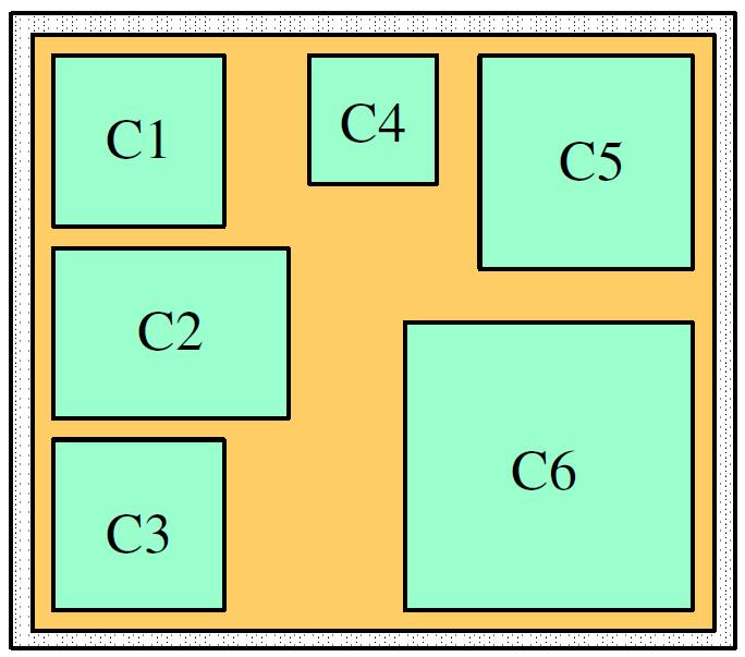
24 Approach Inputs: ibrary of decoupling capacitors Package/Board design with noise source locations Target impedance requirements (impedance, bandwidth) Number of capacitors to place Methodology: Each chromosome is a string containing decap values and corresponding locations GA works on an initial random population Uses concepts of elitism, mutation and crossover Output: Decap values and location that best satisfy target impedance 24
25 GA Encoding and Mechanics 2 No. of capacitors: 5 Chromosome length: 0 3 Parent C C3 C C5 C Parent Child C3 C2 C C4 C Crossover C C3 C C4 C Mutation C C2 C C4 C
26 Fitness Function Z Z target Fitness function: f i N port N freq w Z tar, Z, ( k) w2 Z tar, Z, ( k) k w and w 2 : empirically determined weights Frequency Z tar, : Target impedance (specification) at the th port Z, : Self impedance (simulated) at the th port 26
27 Capacitor ibrary Cap ESR (mω) ES (nh) Res. Freq (GHz) 27 pf nf Cap ESR (mω) ES (nh) Res. Freq (GHz) uf Madhavan Swaminathan and Ege Engin, Power Integrity Modeling and Design for Semiconductors and Systems, Prentice Hall,


28 Results: Placement 50 µm- 70 Capacitors 25 µm- 20 Capacitors 8 µm- 40 Capacitors 28
29 Results: Test Case Z tar 50 µm- 70 Capacitors 25 µm- 20 Capacitors Simulation Specs: - Time/ GA iteration: 20 s - Max iterations: µm- 40 Capacitors 29


30 Test Case 2: Multilayer Structure SSN can couple vertically in multi-layer structures Port 2 Port Decap placement can be optimized to suppress coupling between vertically separated ports Dimensions 2 mm X 97 mm Solid top and bottom layers Number of Decaps : 200 Z tar = 200 mohm 30
31 After Cap Placement No Capacitors Results: Test Case 2 Z tar 3
32 Thank you! 32
33 Reference Node Assignment for Two-Port Admittance Matrices V l I Y A V r V al I al Y A I ar V ar I 2 I bl I br V 2 l Y B V 2r V bl Y B V br Y Y A B V V l 2l Y Y A 2 B 2 V r V 2r I KC equations for isolated systems written When shifting ground of Y A to ground of Y B, enforce node current I bl to contain return I Rewrite KC equations for revised system I Provides complete system matrix 2 Y I V bl where, I Y V Y l I V 2 al I 2 V r ar 2l bl 2r br A A Val Vbl ) Y2 ( Var Vbr ) bl B ; V V B 2 V V V ; V V ( I I I I I I al ar bl br Y Y A A Y bl Y A A Y B V V V V V br bl br al ar br al 33
34 Reference Assignment for Inductances In this case, The combined 4-port system is represented by Can this be represented by an equivalent circuit? 34 Plane Plane 2 Plane 2 Plane 3 V l V 2l V r V 2r Y A Y B Y A Y B Y

/freq point 2 38,800 0.")


35 M-FDM Results: Scalability and Timing Simulation setup: Dual processor 3.2 GHz workstation with 3 GB RAM # ayers # Nodes Time (s)/freq point 2 38, , , , , , , , representative layers of a realistic package 0 349,

36 Introduction VSI design issues Power optimization High performance, low power consumption Multi-function device on single chip Battery operated power saving chip 36
37 Introduction (cont.) Power consumption Active power and dynamic power 37
 Voltage islands Reduce active power and dynamic power Performance critical logics (procesor)use highest voltage Memory and")
38 Introduction (cont.) Voltage islands Reduce active power and dynamic power Performance critical logics (procesor)use highest voltage Memory and control logics use lower voltage Place to nearby power pins evel converters needed Area and delay overhead 38
Signal Integrity Design of TSV-Based 3D IC
 Signal Integrity Design of TSV-Based 3D IC October 24, 21 Joungho Kim at KAIST joungho@ee.kaist.ac.kr http://tera.kaist.ac.kr 1 Contents 1) Driving Forces of TSV based 3D IC 2) Signal Integrity Issues
Design of the Power Delivery System for Next Generation Gigahertz Packages
 Design of the Power Delivery System for Next Generation Gigahertz Packages Madhavan Swaminathan Professor School of Electrical and Computer Engg. Packaging Research Center madhavan.swaminathan@ece.gatech.edu
Broadband Methodology for Power Distribution System Analysis of Chip, Package and Board for High Speed IO Design
 DesignCon 2009 Broadband Methodology for Power Distribution System Analysis of Chip, Package and Board for High Speed IO Design Hsing-Chou Hsu, VIA Technologies jimmyhsu@via.com.tw Jack Lin, Sigrity Inc.
Design, Modeling and Characterization of Embedded Capacitor Networks for Mid-frequency Decoupling in Semiconductor Systems
 Design, Modeling and Characterization of Embedded Capacitor Networks for Mid-frequency Decoupling in Semiconductor Systems Prathap Muthana, Madhavan Swaminathan, Rao Tummala, P.Markondeya Raj, Ege Engin,Lixi
Decoupling Capacitance
 Decoupling Capacitance Nitin Bhardwaj ECE492 Department of Electrical and Computer Engineering Agenda Background On-Chip Algorithms for decap sizing and placement Based on noise estimation Decap modeling
433MHz front-end with the SA601 or SA620
 433MHz front-end with the SA60 or SA620 AN9502 Author: Rob Bouwer ABSTRACT Although designed for GHz, the SA60 and SA620 can also be used in the 433MHz ISM band. The SA60 performs amplification of the
Magnetic-free non-reciprocity and isolation based on parametrically modulated coupled-resonator loops
 Magnetic-free non-reciprocity and isolation based on parametrically modulated coupled-resonator loops Nicholas A. Estep, Dimitrios L. Sounas, Jason Soric, and Andrea Alù * Department of Electrical & omputer
Wire Layer Geometry Optimization using Stochastic Wire Sampling
 Wire Layer Geometry Optimization using Stochastic Wire Sampling Raymond A. Wildman*, Joshua I. Kramer, Daniel S. Weile, and Philip Christie Department University of Delaware Introduction Is it possible
Practical Limitations of State of the Art Passive Printed Circuit Board Power Delivery Networks for High Performance Compute Systems
 Practical Limitations of State of the Art Passive Printed Circuit Board Power Delivery Networks for High Performance Compute Systems Presented by Chad Smutzer Mayo Clinic Special Purpose Processor Development
On Chip Active Decoupling Capacitors for Supply Noise Reduction for Power Gating and Dynamic Dual Vdd Circuits in Digital VLSI
 ELEN 689 606 Techniques for Layout Synthesis and Simulation in EDA Project Report On Chip Active Decoupling Capacitors for Supply Noise Reduction for Power Gating and Dynamic Dual Vdd Circuits in Digital
CIRCUITS. Raj Nair Donald Bennett PRENTICE HALL
 POWER INTEGRITY ANALYSIS AND MANAGEMENT I CIRCUITS Raj Nair Donald Bennett PRENTICE HALL Upper Saddle River, NJ Boston Indianapolis San Francisco New York Toronto Montreal London Munich Paris Madrid Capetown
A Resonance-Free Power Delivery System Design Methodology applying 3D Optimized Extended Adaptive Voltage Positioning.
 A Resonance-Free Power Delivery System Design Methodology applying 3D Optimized Extended Adaptive Voltage Positioning Tao Xu Brad Brim Agenda Adaptive voltage positioning (AVP) Extended adaptive voltage
An Active Decoupling Capacitance Circuit for Inductive Noise Suppression in Power Supply Networks
 An Active Decoupling Capacitance Circuit for Inductive Noise Suppression in Power Supply Networks Sanjay Pant, David Blaauw University of Michigan, Ann Arbor, MI Abstract The placement of on-die decoupling
Low Power System-On-Chip-Design Chapter 12: Physical Libraries
 1 Low Power System-On-Chip-Design Chapter 12: Physical Libraries Friedemann Wesner 2 Outline Standard Cell Libraries Modeling of Standard Cell Libraries Isolation Cells Level Shifters Memories Power Gating
AMultistory Multi-story Power Delivery Technique for 3D Integrated Circuits
 AMultistory Multi-story Power Delivery Technique for 3D ntegrated Circuits Pulkit Jain, Tae-Hyoung Kim, John Keane, and Chris H. Kim University of Minnesota Department of Electrical and Computer Engineering
Ruixing Yang
 Design of the Power Switching Network Ruixing Yang 15.01.2009 Outline Power Gating implementation styles Sleep transistor power network synthesis Wakeup in-rush current control Wakeup and sleep latency
Electromagnetic Analysis of Decoupling Capacitor Mounting Structures with Simbeor
 Simbeor Application Note #2008_01, March 2008 2008 Simberian Inc. Electromagnetic Analysis of Decoupling Capacitor Mounting Structures with Simbeor Simberian, Inc. www.simberian.com Simbeor: Easy-to-Use,
Interconnect-Power Dissipation in a Microprocessor
 4/2/2004 Interconnect-Power Dissipation in a Microprocessor N. Magen, A. Kolodny, U. Weiser, N. Shamir Intel corporation Technion - Israel Institute of Technology 4/2/2004 2 Interconnect-Power Definition
The challenges of low power design Karen Yorav
 The challenges of low power design Karen Yorav The challenges of low power design What this tutorial is NOT about: Electrical engineering CMOS technology but also not Hand waving nonsense about trends
CORRELATION OF PDN IMPEDANCE WITH JITTER AND VOLTAGE MARGIN IN HIGH SPEED CHANNELS
 CORRELATION OF PDN IMPEDANCE WITH JITTER AND VOLTAGE MARGIN IN HIGH SPEED CHANNELS A Thesis Presented to The Academic Faculty By Vishal Laddha In Partial Fulfillment of the Requirements for the Degree
Synthesis of Optimal On-Chip Baluns
 Synthesis of Optimal On-Chip Baluns Sharad Kapur, David E. Long and Robert C. Frye Integrand Software, Inc. Berkeley Heights, New Jersey Yu-Chia Chen, Ming-Hsiang Cho, Huai-Wen Chang, Jun-Hong Ou and Bigchoug
Power Distribution Status and Challenges
 Greetings from Georgia Institute of Institute Technology of Technology Power Distribution Status and Challenges Presented by Madhavan Swaminathan Packaging Research Center School of Electrical and Computer
POWER GATING. Power-gating parameters
 POWER GATING Power Gating is effective for reducing leakage power [3]. Power gating is the technique wherein circuit blocks that are not in use are temporarily turned off to reduce the overall leakage
Data Sheet. VMMK GHz Variable Gain Amplifier in SMT Package. Features. Description. Specifications (6 GHz, Vdd = 5 V, Zin = Zout = 50 Ω)
") VMMK-. - 18 GHz Variable Gain Amplifier in SMT Package Data Sheet Description The VMMK- is a small and easy-to-use, broadband, variable gain amplifier operating in various frequency bands from.-18 GHz.
VMMK-. - 18 GHz Variable Gain Amplifier in SMT Package Data Sheet Description The VMMK- is a small and easy-to-use, broadband, variable gain amplifier operating in various frequency bands from.-18 GHz.
Low-Power VLSI. Seong-Ook Jung VLSI SYSTEM LAB, YONSEI University School of Electrical & Electronic Engineering
 Low-Power VLSI Seong-Ook Jung 2013. 5. 27. sjung@yonsei.ac.kr VLSI SYSTEM LAB, YONSEI University School of Electrical & Electronic Engineering Contents 1. Introduction 2. Power classification & Power performance
A design of 16-bit adiabatic Microprocessor core
 194 A design of 16-bit adiabatic Microprocessor core Youngjoon Shin, Hanseung Lee, Yong Moon, and Chanho Lee Abstract A 16-bit adiabatic low-power Microprocessor core is designed. The processor consists
Foundry WLSI Technology for Power Management System Integration
 1 Foundry WLSI Technology for Power Management System Integration Chuei-Tang Wang, Chih-Lin Chen, Jeng-Shien Hsieh, Victor C.Y. Chang, Douglas Yu R&D,TSMC Oct. 2016 2 Motivation Outline PMIC system integration
Noise Aware Decoupling Capacitors for Multi-Voltage Power Distribution Systems
 Noise Aware Decoupling Capacitors for Multi-Voltage Power Distribution Systems Mikhail Popovich and Eby G. Friedman Department of Electrical and Computer Engineering University of Rochester, Rochester,
UNIT-III POWER ESTIMATION AND ANALYSIS
 UNIT-III POWER ESTIMATION AND ANALYSIS In VLSI design implementation simulation software operating at various levels of design abstraction. In general simulation at a lower-level design abstraction offers
544 IEEE TRANSACTIONS ON ADVANCED PACKAGING, VOL. 31, NO. 3, AUGUST /$ IEEE
 544 IEEE TRANSACTIONS ON ADVANCED PACKAGING, VOL. 31, NO. 3, AUGUST 2008 Modeling and Measurement of Interlevel Electromagnetic Coupling and Fringing Effect in a Hierarchical Power Distribution Network
Features. FREQUENCY 900MHz 1950MHz 2450MHz NF (db) NF (db) IIP3 (dbm) GAIN (db)
 NF (db) IIP3 (dbm) GAIN (db)") EVALUATION KIT AVAILABLE MAX// to.ghz, Low-Noise, General Description The MAX// miniature, low-cost, low-noise downconverter mixers are designed for lowvoltage operation and are ideal for use in portable
EVALUATION KIT AVAILABLE MAX// to.ghz, Low-Noise, General Description The MAX// miniature, low-cost, low-noise downconverter mixers are designed for lowvoltage operation and are ideal for use in portable
CHAPTER 3 NEW SLEEPY- PASS GATE
 56 CHAPTER 3 NEW SLEEPY- PASS GATE 3.1 INTRODUCTION A circuit level design technique is presented in this chapter to reduce the overall leakage power in conventional CMOS cells. The new leakage po leepy-
Active Decap Design Considerations for Optimal Supply Noise Reduction
 Active Decap Design Considerations for Optimal Supply Noise Reduction Xiongfei Meng and Resve Saleh Dept. of ECE, University of British Columbia, 356 Main Mall, Vancouver, BC, V6T Z4, Canada E-mail: {xmeng,
Thank you for downloading one of our ANSYS whitepapers we hope you enjoy it.
 Thank you! Thank you for downloading one of our ANSYS whitepapers we hope you enjoy it. Have questions? Need more information? Please don t hesitate to contact us! We have plenty more where this came from.
Data Sheet. VMMK GHz Positive Gain Slope Low Noise Amplifier in SMT Package. Features. Description
 VMMK-3603 1-6 GHz Positive Gain Slope Low Noise Amplifier in SMT Package Data Sheet Description The VMMK-3603 is a small and easy-to-use, broadband, positive gain slope low noise amplifier operating in
Design Considerations for Highly Integrated 3D SiP for Mobile Applications
 Design Considerations for Highly Integrated 3D SiP for Mobile Applications FDIP, CA October 26, 2008 Joungho Kim at KAIST joungho@ee.kaist.ac.kr http://tera.kaist.ac.kr Contents I. Market and future direction
JANUARY 28-31, 2013 SANTA CLARA CONVENTION CENTER. World s First LPDDR3 Enabling for Mobile Application Processors System
 JANUARY 28-31, 2013 SANTA CLARA CONVENTION CENTER World s First LPDDR3 Enabling for Mobile Application Processors System Contents Introduction Problem Statements at Early mobile platform Root-cause, Enablers
A Survey of the Low Power Design Techniques at the Circuit Level
 A Survey of the Low Power Design Techniques at the Circuit Level Hari Krishna B Assistant Professor, Department of Electronics and Communication Engineering, Vagdevi Engineering College, Warangal, India
AN4819 Application note
 Application note PCB design guidelines for the BlueNRG-1 device Introduction The BlueNRG1 is a very low power Bluetooth low energy (BLE) single-mode system-on-chip compliant with Bluetooth specification
Chapter 5 OPTIMIZATION OF BOW TIE ANTENNA USING GENETIC ALGORITHM
 Chapter 5 OPTIMIZATION OF BOW TIE ANTENNA USING GENETIC ALGORITHM 5.1 Introduction This chapter focuses on the use of an optimization technique known as genetic algorithm to optimize the dimensions of
AN-1098 APPLICATION NOTE
 APPLICATION NOTE One Technology Way P.O. Box 9106 Norwood, MA 02062-9106, U.S.A. Tel: 781.329.4700 Fax: 781.461.3113 www.analog.com Methodology for Narrow-Band Interface Design Between High Performance
Low Power Design for Systems on a Chip. Tutorial Outline
 Low Power Design for Systems on a Chip Mary Jane Irwin Dept of CSE Penn State University (www.cse.psu.edu/~mji) Low Power Design for SoCs ASIC Tutorial Intro.1 Tutorial Outline Introduction and motivation
400 MHz 4000 MHz Low Noise Amplifier ADL5521
 FEATURES Operation from 400 MHz to 4000 MHz Noise figure of 0.8 db at 900 MHz Including external input match Gain of 20.0 db at 900 MHz OIP3 of 37.7 dbm at 900 MHz P1dB of 22.0 dbm at 900 MHz Integrated
COMPACT MICROSTRIP BANDPASS FILTERS USING TRIPLE-MODE RESONATOR
 Progress In Electromagnetics Research Letters, Vol. 35, 89 98, 2012 COMPACT MICROSTRIP BANDPASS FILTERS USING TRIPLE-MODE RESONATOR K. C. Lee *, H. T. Su, and M. K. Haldar School of Engineering, Computing
Wide and multi-band antenna design using the genetic algorithm to create amorphous shapes using ellipses
 Wide and multi-band antenna design using the genetic algorithm to create amorphous shapes using ellipses By Lance Griffiths, You Chung Chung, and Cynthia Furse ABSTRACT A method is demonstrated for generating
A 0.9 V Low-power 16-bit DSP Based on a Top-down Design Methodology
 UDC 621.3.049.771.14:621.396.949 A 0.9 V Low-power 16-bit DSP Based on a Top-down Design Methodology VAtsushi Tsuchiya VTetsuyoshi Shiota VShoichiro Kawashima (Manuscript received December 8, 1999) A 0.9
Inductorless DC-DC Converters for Portable Applications - Reality or Fantasy?
 Inductorless DC-DC Converters for Portable Applications - Reality or Fantasy? Aditya Makharia Advisor: Prof. Gabriel A Rincón- Mora Georgia Tech Analog Consortium School of Electrical and Computer Engineering
CMD GHz Low Noise Amplifier. Functional Block Diagram. Features. Description
 33- GHz Low Noise Amplifier Features Functional Block Diagram Ultra low noise performance All positive bias Low current consumption Small die size 2 3 Vgg GB RFIN Vdd RFOUT Description The CMD9 is a highly
Power Supply Networks: Analysis and Synthesis. What is Power Supply Noise?
 Power Supply Networs: Analysis and Synthesis What is Power Supply Noise? Problem: Degraded voltage level at the delivery point of the power/ground grid causes performance and/or functional failure Lower
Millimeter Wave RF Front End Design using Neuro-Genetic Algorithms
 Millimeter Wave RF Front End Design using Neuro-Genetic Algorithms Rana J. Pratap, J.H. Lee, S. Pinel, G.S. May *, J. Laskar and E.M. Tentzeris Georgia Electronic Design Center Georgia Institute of Technology,
CMD GHz GaN Low Noise Amplifier. Features. Functional Block Diagram. Description
 Features Functional Block Diagram Ultra wideband performance Low noise figure High RF power survivablility Low current consumption Small die size Vdd Vgg2 RFOUT Description RFIN The CMD2 is a wideband
User s Manual ISL70040SEHEV2Z. User s Manual: Evaluation Board. High Reliability
 User s Manual ISL70040SEHEV2Z User s Manual: Evaluation Board High Reliability Rev 0.00 Nov 2017 USER S MANUAL ISL70040SEHEV2Z Evaluation Board for the ISL70040SEH and ISL70023SEH UG147 Rev.0.00 1. Overview
Decoupling capacitor placement
 Decoupling capacitor placement Covered in this topic: Introduction Which locations need decoupling caps? IC decoupling Capacitor lumped model How to maximize the effectiveness of a decoupling cap Parallel
Introduction to Electromagnetic Compatibility
 Introduction to Electromagnetic Compatibility Second Edition CLAYTON R. PAUL Department of Electrical and Computer Engineering, School of Engineering, Mercer University, Macon, Georgia and Emeritus Professor
Substrate Coupling in RF Analog/Mixed Signal IC Design: A Review
 Substrate Coupling in RF Analog/Mixed Signal IC Design: A Review Ashish C Vora, Graduate Student, Rochester Institute of Technology, Rochester, NY, USA. Abstract : Digital switching noise coupled into
A NOVEL DUAL-BAND BANDPASS FILTER USING GENERALIZED TRISECTION STEPPED IMPEDANCE RESONATOR WITH IMPROVED OUT-OF-BAND PER- FORMANCE
 Progress In Electromagnetics Research Letters, Vol. 21, 31 40, 2011 A NOVEL DUAL-BAND BANDPASS FILTER USING GENERALIZED TRISECTION STEPPED IMPEDANCE RESONATOR WITH IMPROVED OUT-OF-BAND PER- FORMANCE X.
W-CDMA Upconverter and PA Driver with Power Control
 19-2108; Rev 1; 8/03 EVALUATION KIT AVAILABLE W-CDMA Upconverter and PA Driver General Description The upconverter and PA driver IC is designed for emerging ARIB (Japan) and ETSI-UMTS (Europe) W-CDMA applications.
Simple Power IC for the Switched Current Power Converter: Its Fabrication and Other Applications March 3, 2006 Edward Herbert Canton, CT 06019
 Simple Power IC for the Switched Current Power Converter: Its Fabrication and Other Applications March 3, 2006 Edward Herbert Canton, CT 06019 Introduction: A simple power integrated circuit (power IC)
Datorstödd Elektronikkonstruktion
 Datorstödd Elektronikkonstruktion [Computer Aided Design of Electronics] Zebo Peng, Petru Eles and Gert Jervan Embedded Systems Laboratory IDA, Linköping University http://www.ida.liu.se/~tdts80/~tdts80
DIO6970 High-Efficiency 2A, 24V Input Synchronous Step Down Converter
 DIO6970 High-Efficiency 2A, 24V Input Synchronous Step Down Converter Rev 0.2 Features Low R DS(ON) for internal switches (top/bottom) 130mΩ/80mΩ, 2.0A 4.5-24V input voltage range High-Efficiency Synchronous-Mode
CMD GHz Low Noise Amplifier. Functional Block Diagram. Features. Description
 Features Functional Block Diagram Ultra low noise performance Low current consumption Small die size GB 3 Vgg Vdd 4 RFIN RFOUT Description The CMD6 is a highly efficient GaAs MMIC low noise amplifier ideally
Implementation of Power Transmission Lines to Field Programmable Gate Array ICs for Managing Signal and Power Integrity
 Implementation of Power Transmission Lines to Field Programmable Gate Array ICs for Managing Signal and Power Integrity Sang Kyu Kim, Satyanarayana Telikepalli, Sung Joo Park, Madhavan Swaminathan and
Chapter 6. Case Study: 2.4-GHz Direct Conversion Receiver. 6.1 Receiver Front-End Design
 Chapter 6 Case Study: 2.4-GHz Direct Conversion Receiver The chapter presents a 0.25-µm CMOS receiver front-end designed for 2.4-GHz direct conversion RF transceiver and demonstrates the necessity and
SMT Hybrid Couplers, RF Parameters and Applications
 SMT Hybrid Couplers, RF Parameters and Applications A 90 degree hybrid coupler is a four-port device used to equally split an input signal into two signals with a 90 degree phase shift between them. The
Low Power High Performance 10T Full Adder for Low Voltage CMOS Technology Using Dual Threshold Voltage
 Low Power High Performance 10T Full Adder for Low Voltage CMOS Technology Using Dual Threshold Voltage Surbhi Kushwah 1, Shipra Mishra 2 1 M.Tech. VLSI Design, NITM College Gwalior M.P. India 474001 2
3 4 ACG1 ACG2. Vgg2 2 RFIN. Parameter Min Typ Max Units Frequency Range
 Features Functional Block Diagram Ultra wideband performance Positive gain slope High output power Low noise figure Small die size 3 4 ACG ACG Vgg RFOUT & Vdd Description RFIN The CMD9 is wideband GaAs
Improvements of LLC Resonant Converter
 Chapter 5 Improvements of LLC Resonant Converter From previous chapter, the characteristic and design of LLC resonant converter were discussed. In this chapter, two improvements for LLC resonant converter
Two-Port Networks I. Dr. Mohamed Refky Amin
 Two-Port Networks I Amin Electronics and Electrical Communications Engineering Department (EECE) Cairo University elc.n112.eng@gmail.com http://scholar.cu.edu.eg/refky/ OUTLINE Introduction The Impedance
High Speed PWM Controller
 High Speed PWM Controller application INFO available FEATURES Compatible with Voltage or Current Mode Topologies Practical Operation Switching Frequencies to 1MHz 50ns Propagation Delay to Output High
PCB Design Guidelines for GPS chipset designs. Section 1. Section 2. Section 3. Section 4. Section 5
 PCB Design Guidelines for GPS chipset designs The main sections of this white paper are laid out follows: Section 1 Introduction Section 2 RF Design Issues Section 3 Sirf Receiver layout guidelines Section
UM1660. Low Power DC/DC Boost Converter UM1660S SOT23-5 UM1660DA DFN AAG PHO. General Description
 General Description Low Power DC/DC Boost Converter S SOT23-5 DA DFN6 2.0 2.0 The is a PFM controlled step-up DC-DC converter with a switching frequency up to 1MHz. The device is ideal to generate output
20 MHz to 6 GHz RF/IF Gain Block ADL5542
 FEATURES Fixed gain of db Operation up to 6 GHz Input/output internally matched to Ω Integrated bias control circuit Output IP3 46 dbm at MHz 4 dbm at 9 MHz Output 1 db compression:.6 db at 9 MHz Noise
1 Digital EE141 Integrated Circuits 2nd Introduction
 Digital Integrated Circuits Introduction 1 What is this lecture about? Introduction to digital integrated circuits + low power circuits Issues in digital design The CMOS inverter Combinational logic structures
Effect of Power Distribution Network Design on RF circuit performance for 900MHz RFID Reader
 Effect of Power Distribution Network Design on RF circuit performance for 900MHz RFID Reader Youngwon Kim, Chunghyun Ryu, Jongbae Park, and Joungho Kim Terahertz Interconnection and Package Laboratory,
Suppression Techniques using X2Y as a Broadband EMI Filter IEEE International Symposium on EMC, Boston, MA
 Suppression Techniques using X2Y as a Broadband EMI Filter Jim Muccioli Tony Anthony Dave Anthony Dale Sanders X2Y Attenuators, LLC Erie, PA 16506-2972 www.x2y.com Email: x2y@x2y.com Bart Bouma Yageo/Phycomp
Efficient FDTD parallel processing on modern PC CPUs
 Efficient FDTD simulations 1 of 8 Efficient FDTD parallel processing on modern PC CPUs Efficient FDTD simulations W. Simon, A. Lauer, D. Manteuffel, A. Wien, I.Wolff IMST GmbH, Carl-Friedrich-Gauss-Str.
T est POST OFFICE BOX 1927 CUPERTINO, CA TEL E P H ONE (408) FAX (408) ARIES ELECTRONICS
 FAX (408) ARIES ELECTRONICS") G iga T est L abs POST OFFICE BOX 1927 CUPERTINO, CA 95015 TEL E P H ONE (408) 524-2700 FAX (408) 524-2777 ARIES ELECTRONICS BGA SOCKET (0.80MM TEST CENTER PROBE CONTACT) Final Report Electrical Characterization
G iga T est L abs POST OFFICE BOX 1927 CUPERTINO, CA 95015 TEL E P H ONE (408) 524-2700 FAX (408) 524-2777 ARIES ELECTRONICS BGA SOCKET (0.80MM TEST CENTER PROBE CONTACT) Final Report Electrical Characterization
LF to 4 GHz High Linearity Y-Mixer ADL5350
 LF to GHz High Linearity Y-Mixer ADL535 FEATURES Broadband radio frequency (RF), intermediate frequency (IF), and local oscillator (LO) ports Conversion loss:. db Noise figure:.5 db High input IP3: 25
PCB power supply noise measurement procedure
 PCB power supply noise measurement procedure What has changed? Measuring power supply noise in high current, high frequency, low voltage designs is no longer simply a case of hooking up an oscilloscope
400 MHz to 4000 MHz ½ Watt RF Driver Amplifier ADL5324
 Data Sheet FEATURES Operation from MHz to MHz Gain of 14.6 db at 21 MHz OIP of 4.1 dbm at 21 MHz P1dB of 29.1 dbm at 21 MHz Noise figure of.8 db Dynamically adjustable bias Adjustable power supply bias:.
Noise Constraint Driven Placement for Mixed Signal Designs. William Kao and Wenkung Chu October 20, 2003 CAS IEEE SCV Meeting
 Noise Constraint Driven Placement for Mixed Signal Designs William Kao and Wenkung Chu October 20, 2003 CAS IEEE SCV Meeting Introduction OUTLINE Substrate Noise: Some Background Substrate Noise Network
ECEN689: Special Topics in High-Speed Links Circuits and Systems Spring 2012
 ECEN689: Special Topics in High-Speed Links Circuits and Systems Spring 2012 Lecture 5: Termination, TX Driver, & Multiplexer Circuits Sam Palermo Analog & Mixed-Signal Center Texas A&M University Announcements
A Solution to Simplify 60A Multiphase Designs By John Lambert & Chris Bull, International Rectifier, USA
 A Solution to Simplify 60A Multiphase Designs By John Lambert & Chris Bull, International Rectifier, USA As presented at PCIM 2001 Today s servers and high-end desktop computer CPUs require peak currents
An Enhanced Design Methodology for Resonant Clock. Trees
 An Enhanced Design Methodology for Resonant Clock Trees Somayyeh Rahimian, Vasilis Pavlidis, Xifan Tang, and Giovanni De Micheli Abstract Clock distribution networks consume a considerable portion of the
LC Resonant Circuits Dr. Roger King June Introduction
 LC Resonant Circuits Dr. Roger King June 01 Introduction Second-order systems are important in a wide range of applications including transformerless impedance-matching networks, frequency-selective networks,
Fast Placement Optimization of Power Supply Pads
 Fast Placement Optimization of Power Supply Pads Yu Zhong Martin D. F. Wong Dept. of Electrical and Computer Engineering Dept. of Electrical and Computer Engineering Univ. of Illinois at Urbana-Champaign
Leakage Power Minimization in Deep-Submicron CMOS circuits
 Outline Leakage Power Minimization in Deep-Submicron circuits Politecnico di Torino Dip. di Automatica e Informatica 1019 Torino, Italy enrico.macii@polito.it Introduction. Design for low leakage: Basics.
Course Introduction. Content 15 pages. Learning Time 30 minutes
 Course Introduction Purpose This course discusses techniques for analyzing and eliminating noise in microcontroller (MCU) and microprocessor (MPU) based embedded systems. Objectives Learn about how packaging
Through-Silicon-Via Inductor: Is it Real or Just A Fantasy?
 Through-Silicon-Via Inductor: Is it Real or Just A Fantasy? Umamaheswara Rao Tida 1 Cheng Zhuo 2 Yiyu Shi 1 1 ECE Department, Missouri University of Science and Technology 2 Intel Research, Hillsboro Outline
EE241 - Spring 2004 Advanced Digital Integrated Circuits. Announcements. Borivoje Nikolic. Lecture 15 Low-Power Design: Supply Voltage Scaling
 EE241 - Spring 2004 Advanced Digital Integrated Circuits Borivoje Nikolic Lecture 15 Low-Power Design: Supply Voltage Scaling Announcements Homework #2 due today Midterm project reports due next Thursday
Design Fundamentals by A. Ciccomancini Scogna, PhD Suppression of Simultaneous Switching Noise in Power and Ground Plane Pairs
 Design Fundamentals by A. Ciccomancini Scogna, PhD Suppression of Simultaneous Switching Noise in Power and Ground Plane Pairs Photographer: Janpietruszka Agency: Dreamstime.com 36 Conformity JUNE 2007
CMD GHz Distributed Low Noise Amplifier RFIN
 - GHz Distributed Low Noise Amplifier Features Wide bandwidth Single positive supply voltage Low noise figure Small die size Description Applications Wideband communication systems Point-to-point radios
INVENTION DISCLOSURE- ELECTRONICS SUBJECT MATTER IMPEDANCE MATCHING ANTENNA-INTEGRATED HIGH-EFFICIENCY ENERGY HARVESTING CIRCUIT
 INVENTION DISCLOSURE- ELECTRONICS SUBJECT MATTER IMPEDANCE MATCHING ANTENNA-INTEGRATED HIGH-EFFICIENCY ENERGY HARVESTING CIRCUIT ABSTRACT: This paper describes the design of a high-efficiency energy harvesting
EMI Reduction on an Automotive Microcontroller
 EMI Reduction on an Automotive Microcontroller Design Automation Conference, July 26 th -31 st, 2009 Patrice JOUBERT DORIOL 1, Yamarita VILLAVICENCIO 2, Cristiano FORZAN 1, Mario ROTIGNI 1, Giovanni GRAZIOSI
High Speed PWM Controller
 High Speed PWM Controller FEATURES Compatible with Voltage or Current Mode Topologies Practical Operation Switching Frequencies to 1MHz 50ns Propagation Delay to Output High Current Dual Totem Pole Outputs
Towards a Reconfigurable Nanocomputer Platform
 Towards a Reconfigurable Nanocomputer Platform Paul Beckett School of Electrical and Computer Engineering RMIT University Melbourne, Australia 1 The Nanoscale Cambrian Explosion Disparity: Widerangeof
GENETIC ALGORITHM BASED SOLUTION IN PWM CONVERTER SWITCHING FOR VOLTAGE SOURCE INVERTER FEEDING AN INDUCTION MOTOR DRIVE
 AJSTD Vol. 26 Issue 2 pp. 45-60 (2010) GENETIC ALGORITHM BASED SOLUTION IN PWM CONVERTER SWITCHING FOR VOLTAGE SOURCE INVERTER FEEDING AN INDUCTION MOTOR DRIVE V. Jegathesan Department of EEE, Karunya
Hot Topics and Cool Ideas in Scaled CMOS Analog Design
 Engineering Insights 2006 Hot Topics and Cool Ideas in Scaled CMOS Analog Design C. Patrick Yue ECE, UCSB October 27, 2006 Slide 1 Our Research Focus High-speed analog and RF circuits Device modeling,
Advanced Techniques for Using ARM's Power Management Kit
 ARM Connected Community Technical Symposium Advanced Techniques for Using ARM's Power Management Kit Libo Chang( 常骊波 ) ARM China 2006 年 12 月 4/6/8 日, 上海 / 北京 / 深圳 Power is Out of Control! Up to 90nm redu
CMD GHz Low Noise Amplifier. Features. Functional Block Diagram. Description
 Features Functional Block Diagram Ultra low noise performance High linearity Small die size 2 GB 3 Vgg Vdd 4 RFIN RFOUT Description The CMD63 is a high dynamic range GaAs MMIC low noise amplifier ideally