A short introduction to Protection and Automation Philosophy
|
|
|
- Melissa Gibson
- 5 years ago
- Views:
Transcription

1 Training Center A short introduction to Protection and Automation Philosophy Philippe Goossens & Cédric Moors
2 Training Center Contents Definitions and basic concepts Differential and distance protection functions a short introduction Protection system of 150 / 220 / 380 kv interconnections Protection system of busbars Protection system of transformers between busbars Bay arrangements Transformer 150 / 70 teed on 150 kv interconnection line 2 2

3 Training Center Definitions and basic concepts
4 Training Center What is a fault? In the context of this lecture, a fault is: a low-resistance connection between two points in an electric circuit through which the current tends to flow rather than along the Intended path Faults are characterized by: -Their nature Typical examples: 1-phase / 2-phase / 3-phase, phase-to-phase / phase-toground, metallic / with arc resistance, transient / permanent -Their cause Typical examples: lightning strokes, equipment failure, human errors... -Their consequences Direct consequences are low voltage(s) and / or high current(s) 4 4
5 Training Center Typical example 1-phase fault on a overhead line resulting from a lightning strike 5

6 Training Center Surge arrester Goal: stop the propagation of the overvoltage wave travelling on the transmission line 6
7 Training Center Typical example 1-phase fault on a overhead line resulting from a lightning strike 7 7
8 Training Center Typical example 1-phase fault on a overhead line resulting from a lightning strike 2 ka 2 ka 2 ka 2 ka 10 ka 2 ka 12 ka 6 ka 6 ka Uo = U 4 + U 8 + U 12 3 Io = I 4 + I 8 + I

9 Training Center What is a fault? Type of faults registered on the 380 kv between 2006 and
10 Training Center What is a fault? Faults restistance values registered on the 380 kv between 2008 and
11 Training Center What is a fault? Faults can also have important impacts: - Safety - Thermal effects on equipment, with risk of damage / destructions - Mechanical efforts on equipment, with risk of damage / destructions - System instability - Customers installations / processes (power quality / voltage dips) Once a fault happens, it must be eliminated as fast as possible 11 11
12 Training Center What is a protection system? A protection system is the set of equipment and functions aimed at detecting a fault and tripping the network component where this fault is located. Main components of a protection system: Measurement transformers: Current Transformers (CTs) and Voltage Transformers (VTs) Protection function(s): makes the decision to trip the circuit breaker from CTs and VTs measurements Circuit breaker: trips the network component and interrupts the shortcircuit current This lecture is limited to equipment protections (system protections are not considered) 12
13 Training Center What is a protection system? A protection system does not only relate to one bay, but to a set of bays through appropriate coordindation of the corresponding protection functions 13
 Current transformer Can introduce measurement errors and saturate (large current measured during fault)")
14 Training Center Measurement transformers Measurement transformers are devices designed to provide in their secondary coil a signal proportional to the voltage or current in its primary side Voltage transformer Can introduce measurement errors but cannot saturate (low voltage during faults) Current transformer Can introduce measurement errors and saturate (large current measured during fault) Saturation must be avoided during the time required by the protection to make the decision to trip, through appropriate design of the CT (max Icc, burden on secondary side, precision class) 14 14

15 Training Center Circuit breakers Circuit breakers are devices designed to energize / trip network components, with the possibility to interrupt shortcircuit currents. Main characteristics of a circuit breaker: - Nominal voltage - Shortcircuit current - Medium used for arc extinction: SF6, vacuum, air blast, CO2 - Max I²t allowed - Speed of operation 15 15
16 Training Center Characteristics of protections Protection systems can be characterized with the following attributes: - Dependability: «A dependable protection is one that always operates for conditions for which it is designed to operate» [3] - Security: «A secure protection is one that will not operate for conditions for which it is not intended to operate» [3] Dependability enhancement leads to Security worsening, and Security enhancement leads to Dependability worsening 2 protection functions: - more Dependable - but less Secure [3] The Electrical Engineering Handbook, IEEE press, pp
17 Training Center Characteristics of protections - Reliability: the protection system is both dependable and secure, according to the level of dependability and security for which it has been designed - Selectivity of a protection system: the circuit breakers that must be tripped to eliminate the fault are the only ones to be tripped Selectivity OK Selectivity NOK Tripped CB Tripped CB - Speed: relates to the time needed by the protection system to eliminate the fault 17 17
 - Differential protection function (see next slides) -")

18 Training Center Main type of protection functions Most usual protection functions used in TSO application: - Distance protection function (see next slides) - Differential protection function (see next slides) - Under/overcurrent protection function - Under/overvoltage protection function Nowadays, protection functions are implemented through numerical relays. Several protection functions can be used in the same physical device
19 Training Center Protection system design Designing a protection system consists in deciding which protection functions and devices must be implemented at the various substations / bays in order to fulfill the requirements stated in the grid code (see below), while ensuring a good level of selectivity and reliablity
20 Training Center Differential and distance protection functions
21 Training Center Differential protection First Kirchoff law: at any node in an electrical circuit, the sum of currents flowing into that node is equal to the sum of currents flowing out of that node. I 1 I 2 Σ I = 0 I 3 I 4 If the sum of all currents is not 0, there is a fault at the node Application to overhead lines (shunt capacitors neglected): No fault: I1 + I2 = 0 Fault: I1 + I2 0 21
22 Training Center Differential protection I diff = I 1 + I 2 Fault I diff I stab = 0,5 I 1 I 2 No fault Why stabilizing current and 2- slopes characteristic? Shunt capacitors On-load tap changers CTs errors CTs saturation I 22
23 Training Center Telecommunication typical implementation 3-end line differential protection with direct communication through dedicated optical fiber (FO) 2-end line differential protection with communication through TDM («Access») network 23
24 Training Center Differential protection Differential principle applied to lines, cables, transfos and busbars Main characteristics: - Naturally selective - Dependability and security barely dependant from network environment (short-circuits power at different ends, direct and zero-sequence impedances ) - Requires CTs compatibility at all ends - Requires permanent communication between the different ends (with symetrical paths) - Differential protections must be replaced at all ends at the same time (no interoperability between different manufacturers / generations of devices) 24
25 Training Center Distance protection 3-ph fault without arc resistance I I Z d V V Fault R f Z t k0 Z d V I Z d with Zd proportional to the distance between the busbar and the place of the fault Conclusion: measurement of local voltages and currents allows to estimate the distance to the fault 25
26 Training Center Distance protection 2 Locate Zd in the Z, R plane 1 From V and I, calculate Zd 2 3 Fault in zone 1 trip after t1 (0 ms) A P Z 1 t 1 B Z 2 t 2 Z 3 t 3 Z 1 t 1 Z 2 t 2 P P Z 3 t 3 26
27 Training Center Distance protection Each zone is characterized by: Resistance and reactance limits Direction (forward / reverse) Time delay Zone 1: identification of a fault on the line, reactance limit usually set to 80% of the direct impedance of the line. Instantaneous tripping (decision after 30 ms) Zone 2: backup for next forward busbar (busbar fault or circuit breaker failure in the corresponding bays). Reactance limit usually set to 120% of the direct impedance of the line. Typical Tripping time: 500 ms. Zone 3: backup for next forward lines. Reactance limit usually set to cover the longest line. Typical tripping time: 900 ms. 27
28 Training Center Distance protection Impact of fault resistance for 3-phase faults I I d I Z d I d V V R f Z t k0 Z d V I Z d R Impedance to measure f R f I I d Error 28
29 Training Center Distance protection Impact of fault resistance for 1-phase faults I I d I Z d I d V V R f I I d Zt k0 Z d Impedance to measure V R f R f Zd I( 1 k ) 1 k k Error The value of K0 must be provided to the relay in order to compensate its effect I I d 29
30 Training Center Distance protection Distance principle applied to lines, cables, transformers Main characteristics: - Selectivity eached through distance protection settings coordination in various bays - Dependability and security strongly dependent from network environment (short-circuits power at different ends, k0 factor, fault resistance ) - Does not requires CTs compatibility at all ends - Requires communication between different ends (only if POTT logic applied, see next slides) - Distance protections must not be identical at all ends 30
 40 (prot.")
31 Training Center Telecommunication infrastructure requirements Conv Conv - Fault clearing time objective at 380 kv: 100 ms (CB time included) - Performance target for communication channel: (CB time) 40 (prot. decision) 15 (converter) = 5 ms - Other constraints: asymmetry on communication paths < 0,3 ms (current differential protection) 31


32 Training Center Telecommunication infrasructure overview Satellite PROXIMUS NETWORK TELEPHONY SCADA SERVERS Optical TELEPHONY Optical SCADA Optical Optical Radio PROT Optical Optical SERVERS Optical PROT Copper PROT Optical Optical HV SUBSTATION 32
33 Training Center Protection system of 150 / 220 / 380 kv interconnections
34 Training Center Protection system design One of the protections must be a distance protection Two independant protections priority to dependability Consistent with N-1 criterium 34 34
35 Protection scheme150 / 220 / 380 interconnection link Backward (BW) Forward (FW) P1 protection = distance protection with POTT teleprotection logic (see next slides) P2 protection = line differential protection Communication channels: Distance protection: one for POTT logic Line differential protection: one for transmission of currents measurements 35
36 Protection scheme150 / 220 / 380 interconnection link Distance protection zones definition 500 ms 900 ms F1 F2 F3 F4 F5 For this fault: tripping after 550 ms if the line differential protection is not in operation not consistent with grid code requirement 36
37 POTT logic POTT = Protective Overreach Transfer Trip t = 0 ms ZTPR = teleprotection zone 37
38 POTT logic Distance protection on B side detects the fault in TPR zone Sending of the corresponding TPR signal to A side t = 30 ms 38
39 POTT logic The TPR signal arrives to A side, where the distance protection has also detected the fault in TPR zone from t = 30 ms tripping decision without waiting unitl t2 t = 50 ms 39
40 POTT logic Circuit breaker trips on B side t = 80 ms 40
41 POTT logic Circuit breaker trips on A side t = 100 ms 41
42 Training Center Telecommunication typical implementation 2-end line teleprotection with direct communication through dedicated optical fiber 2-end teleprotection with communication through TDM («Access») / Proximus network 42
43 Autoreclose function The autoreclose function is an automatism aimed at reclosing the line as fast as possible (short delay) once the fault has been eliminated, in order to maximize its availability Justification: Most of the faults on overhead lines are not permanent (typical example: lightning strikes), they disappear after arc extinction This function is particularly useful during thunderstorms (several trippings in short periods of time) Principles: Only one tentative is allowed. If the fault is still present, definitive 3-ph tripping of the line. From 150 kv to 380 kv: 1-phase fault: 1-phase tripping, followed by a 1-phase autoreclose attempt 2- and 3-phase faults: 3-phase tripping followed by a 3-phase autoreclose attempt No autoreclose function on cables, transformers and busbars (most of the time: permanent fault) 43
 of slow (10 s) Through send couple logic Half-fast (1 1,5s) of slow (10 s) Through send couple logic.")
44 Autoreclose function kv kv kv 380 kv 1-phase fault None None 1 s 1 s 3-phase fault None Half-fast (1 1,5s) of slow (10 s) Through send couple logic Half-fast (1 1,5s) of slow (10 s) Through send couple logic Half-fast (1 1,5s) of slow (10 s) Through send couple logic. 44
45 Send couple logic Only used with manual closing and 3 phase autoreclose function, in order to prevent false parallels Implemented through synchrocheck function Before transmitting the closing order to the circuit breaker, the synchrocheck checks that one of the following conditions is fulfilled: Send condition: voltage on busbar side, no voltage on line side Couple condition: voltage on both sides of the circuit breakers, with the following condition simultaneously met: - ΔU < 10% - Δφ < 20 - Δf < 20mHz 45
46 Illustration on 3 autreclose t = 0 ms 2 of 3 fault 46
47 Illustration on 3 autreclose t 30 ms Trip protection Trip 2 of 3 fault Trip 47
48 Illustration on 3 autreclose t = 80 ms Fault eliminated 48
49 Illustration on 3 autreclose t = 1 s Send Each end of the line must be assigned to send or couple
50 Illustration on 3 autreclose t = 1,5 s Couple 50
51 Illustration on 1 autreclose t = 0 ms 1 fault 51
52 Illustration on 1 autreclose t 30 ms Trip protections Phase 4 Trip phase 4 1 fault Trip phase 4 52
53 Illustration on 1 autreclose t = 80 ms Fault eliminated 53
54 Illustration on 1 autreclose t = 1 s Autoreclose at both sides 54
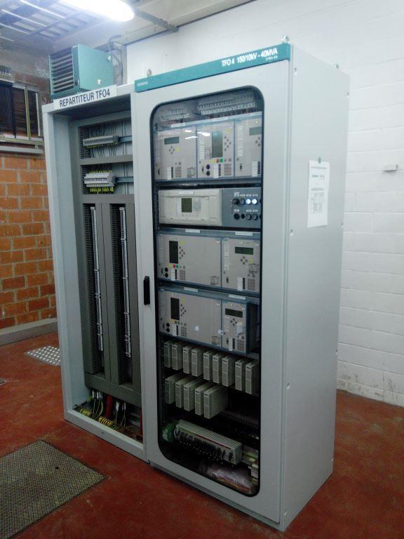
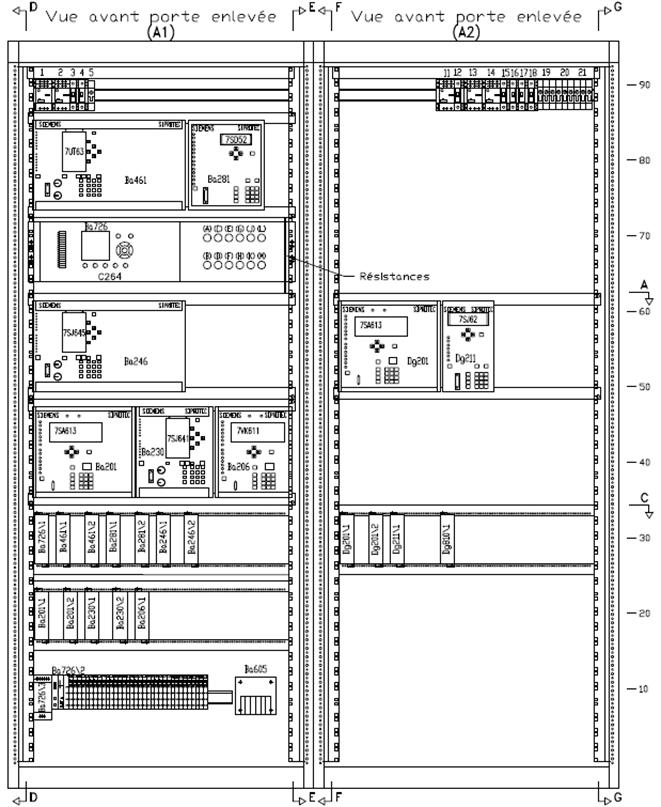
55 Implementation 55
56 Training Center Protection system of busbars
57 Training Center Busbar and circuit breaker failure protection One main protection is sufficient to cover busbar faults Backup protections provided by distance protections 150 kv 380 kv: all substations equippd with busbar and CB failure protections 30 kv 110 kv: 2-busbar substations equipped with busbar and CB failure protections The CB failure protection is implemented in the busbar protection 57 57
58 Busbar protection principle Main protection = differential protection Each busbar is equipped with it own differential function, in order to trip only one busbar in case of fault Each differential function must know at each time which bay is connected to which busbar Example: fault F1 on R1 t = 0 ms F1 58
59 Busbar protection principle t 10 to 20 ms 3-phase trip of R1 differential protection F1 59
60 Busbar protection principle t 60 to 70ms Fault eliminated 60
, there is only one")

61 Busbar protection principle During the transfer of one bay from one busbar to the other (both disconnectors closed), there is only one dfferential function.that protects both busbars In case of a busbar fault at that moment: both busbars are tripped Fault F1 on R1: F1 61
62 Busbar protection principle If the busbar protection is out of service, the fault will be eliminated by the distance protections Coordination of the distance protection of the coupler with the distance protection of the lines is critical to optimize the security of the protection system 62
63 Busbar protection principle - illustration t = 0 ms Fault F1 F1 63
64 Busbar protection principle - illustration t = 250 ms Tripping of the coupler F1 64
65 Busbar protection principle - illustration t = 500 ms Tripping through zone 2 of distance protections F1 (*) (*) tripping initiated by the opening of the CB on primary side 65
66 Busbar protection principle - illustration t = 550 ms Fault elimination F1 (*) (*) tripping initiated by the opening of the CB on primary side 66
67 Busbar protection principle - illustration t = 5 TRIP(*) TRIP(*) (*) tripping through clearing function (automatism) 67
68 Busbar protection principle - illustration t = 5,7 (*) IN (*) circuit breaker clausing though fast transfer function (automatism) 68
69 Circuit breaker failure without CB failure protection t = 0 Fault F F 69
70 Circuit breaker failure without CB failure protection t = 120 ms Circuit breaker failure (no tripping) F 70
71 Circuit breaker failure without CB failure protection t 1000 ms Tripping through zone 2 or zone 3 of distance protections CB failure F 71
72 Circuit breaker failure without CB failure protection t 1050 ms Fault eliminated Both busbars lost due to the failure of a single equipment CB failure 72
73 CB failure protection principle The tripping signal issued by bay protections is sent to the circuit breaker and to the CB failure protection at the same time If current is still flowing through the CB 170 ms after the fault occurence, the other bays connected to the same busbar are tripped Consequence: the CB failure protection is implemented in the busbar protection 170 ms 73
74 CB failure protection principle t = 0 ms Fault 74
75 CB failure protection principle t = 30 ms Trip issued by bay protections 75
76 CB failure protection principle t = 80 ms CB failure CB tripped 76
77 CB failure protection principle t = 90 ms No current CB failure protection reset 77
78 CB failure protection principle t = 200 ms (170 ms after start back-up): trip to other bays 78
79 CB failure protection principle t = 250 ms Fault eliminated 79
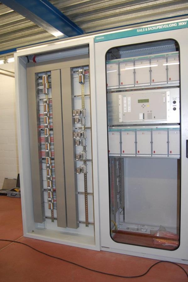
80 Implementation 80
81 Training Center Protection system of transformers between busbars
82 Protection system design One of the protections must be a distance protection Two independant protections for each part of the protection zone priority to dependability Consistent with N-1 criterium 82
83 Transformer protection principle Z1 500 ms Zp 0 ms P1 Distance protections on primary side of the transformer: one zone to detect F1 fault, one zone to detect busbar fault on primary side F1 F2 F3 Internal protection of the transformer (Buchholz): only able to detect internal faults through oil move detection (F2) Distance protections on secondary side of the transformer: one zone to detect F3 fault, one zone to detect busbar fault on secondary side P2 Differentia protection (able to detect F1, F2 and F3 faults) 83
84 Training Center Bay arrangements
85 Double busbar one breaker substation arrangement Training Center One circuit breaker for each bay Main advantages: Any bay can be connected to any busbar without loss of supply Cost Main drawbacks Loss of supply in case of busbar fault Loss of supply during circuit breaker maintenance Disconnector operation needed to supply any bay from the other busbar 85
86 Training Center One and Half substation arrangement 3 circuit breakers used to feed 2 bays 1,5 circuit breaker for each bay Main advantages: No loss of supply in case of busbar fault No loss of supply during circuit breaker maintenance No disconnector operation needed to supply any bay from the other busbar Main drawbacks : Cost (more circuit breakers) Complexity of protections and relaying 86
87 Training Center Ring bus substation arrangement No «classical» busbar, ring topology Main advantages: No loss of supply during circuit breaker maintenance Main drawbacks : Difficult to extend with a new bay Very bad reliability if one circuit breaker is out of operation 87
88 Sequence to switch one bay from busbar 1 to busbar 2 Training Center 1. Close the CB of the bus coupler and block any tripping 2. Close disconnector to busbar 2 3. Open disconnector to busbar 1 4. Release CB of the bus coupler BB1 BB2 88

89 Sequence to switch one bay from busbar 1 to busbar 2 Training Center 1. Close the CB of the bus coupler and block any tripping 2. Close disconnector to busbar 2 3. Open disconnector to busbar 1 4. Release CB of the bus coupler BB1 BB2 89
90 Sequence to switch one bay from busbar 1 to busbar 2 Training Center 1. Close the CB of the bus coupler and block any tripping 2. Close disconnector to busbar 2 3. Open disconnector to busbar 1 4. Release CB of the bus coupler BB1 BB2 90
91 Sequence to switch one bay from busbar 1 to busbar 2 Training Center 1. Close the CB of the bus coupler and block any tripping 2. Close disconnector to busbar 2 3. Open disconnector to busbar 1 4. Release CB of the bus coupler BB1 BB2 91
92 Training Center Transformer 150/70 kv teed on 150 kv interconnection line
93 Transformer 150/70 kv teed on 150 kv interconnection line Interconnection 150 kv Busbar150 kv Busbar 150 kv Connection point Teed150/70 kv transformer 93
94 Transformer 150/70 kv teed on 150 kv interconnection line P2 protection = 3-ends line differential protection Communication channel between each protection Instantaneous tripping of any fault on the interconnection line 94
95 Transformer 150/70 kv teed on 150 kv interconnection line P1 = protection 2 distance protections with POTT logic between A and B ends, and remote tripping of the transformer (validation through local criterium) Communication channel between A and B ends (POTT), and between A and C ends 95
96 Transformer 150/70 kv teed on 150 kv interconnection line 3 zones: Z1: covers. 80% of the line Z2: covers the next busbar (backup for busbar faults) Ztpr must cover the complete line, including a part of the transformer 96
97 Transformer 150/70 kv teed on 150 kv interconnection line 2 zones towards the line 2 zones towards the transfo 97
98 Transformer 150/70 kv teed on 150 kv interconnection line 2 zones towards the transfo 2 zones towards busbar 98
99 Transformer 150/70 kv teed on 150 kv interconnection line F1 F2 F3 P1 Distance protections on primary side of the transformer: one zone to detect F1 fault Internal protection of the transformer (Buchholz): only able to detect internal faults through oil move detection (F2) Distance protections on secondary side of the transformer: one zone to detect F3 fault P2 Differentia protection (able to detect F1, F2 and F3 faults) 99
100 Transformer 150/70 kv teed on 150 kv interconnection line 100
101 Transformer 150/70 kv teed on 150 kv interconnection line 1) t = 0 ms F Fault F 3-phase fault F beyond 85% of the line. Line differential protection out of service How will the fault be eliminated? 101
102 Transformer 150/70 kv teed on 150 kv interconnection line 2) t = 30 ms Tx F Trip The fault is seen in zone 1 by distance protection P1 at B end Tripping order to Db circuit breaker Tx transmission to end A (POTT) 102
103 Transformer 150/70 kv teed on 150 kv interconnection line Tx 3) t = 40 ms Trip F Rx Trip Tx The fault is seen in zone Zptr by the distance protection at end A & reception Rx from end B (POTT) Tripping order to Da circuit breaker Transmission Tx to end C 103
104 Transformer 150/70 kv teed on 150 kv interconnection line Tx 4) t = 50 ms Trip F Rx Trip Tx Rx Trip Receptionl Rx from A side & validation through local criterium 3U<ph/n Tripping order to Dc circuit breaker 104
105 Transformer 150/70 kv teed on 150 kv interconnection line 5) t = 80 ms Trip Rx Tx F Rx Trip Db tripped 105
106 Transformer 150/70 kv teed on 150 kv interconnection line 7) t = 90 ms Trip Rx Tx F Rx Trip Da tripped 106
107 Transformer 150/70 kv teed on 150 kv interconnection line 8) t = 100 ms Rx Trip Dc tripped Fault eliminated 107
108 Transformer 150/70 kv teed on 150 kv interconnection line 9) t = 100 ms Automatic tripping order to dc from open position Dc Meename 108
109 Transformer 150/70 kv teed on 150 kv interconnection line 10) t = 150 ms Tripped dc Transfo 150/70 kv out of service 109
110 Transformer 150/70 kv teed on 150 kv interconnection line Autoreclose 11) t = ~ 1,1 s 1 s Closing order sent to circuit breaker on A side thorgh Send function? 110
111 Transformer 150/70 kv teed on 150 kv interconnection line Autoreclose 12) t = ~ 1,2 s Closed Da circuit breaker Line under voltage 111
112 Transformer 150/70 kv teed on 150 kv interconnection line Autoreclose 1,5 s 13) t = ~ 1,6 s Closing order sent to B end ( couple function) Closing order sent t Dc ( Send function) 1,5 s 112
113 Transformer 150/70 kv teed on 150 kv interconnection line Autoreclose 14) t = ~ 1,7 s Closed CB at B end Closed Dc CB 113
114 Transformer 150/70 kv teed on 150 kv interconnection line Autoreclose 14) t = ~ 1,72 s Closed CB at side Dc 114
115 Transformer 150/70 kv teed on 150 kv interconnection line Autoreclose 15) t = ~ 1,8 s Closed CB at C side ( couple function) 115
116 Transformer 150/70 kv teed on 150 kv interconnection line F 3-phase fault between the Dc CB and the transformer. How will the fault be eliminated? 116
117 Transformer 150/70 kv teed on 150 kv interconnection line 1) t = 0 ms 3-phase fault F F 117
118 Transformer 150/70 kv teed on 150 kv interconnection line 2) t = 25 ms C end: tripping order sent to Dc and dc by transformer differential protection F 118
119 Transformer 150/70 kv teed on 150 kv interconnection line 3) t = 30 ms C end: distance protection at 150 kv side of the tranformer sees the faul in the first zone towards transformer and send tripping orders to DC F Towards Line Towards transformer 119
120 Transformer 150/70 kv teed on 150 kv interconnection line 4) t = 30 ms Tx Tx A and B ends: distance protections see the fault in Ztpr zone. Afstandsbeveiliging ziet de fout in Ztpr and send een POTT signal to the other end F 120
121 Transformer 150/70 kv teed on 150 kv interconnection line 5) t = 40 ms Tx Tx Rx Rx Tx A and B ends: distance protections see the fault in Ztpr zone and receive POTT signals. tripping order sent to Da and Db, translission of tripping signal towards C end F 121
122 Transformer 150/70 kv teed on 150 kv interconnection line 6) t = 60 ms Tx Rx Receptionl Rx from A side & validation through local criterium 3U<ph/n F Tripping order to Dc circuit breaker 122
123 Transformer 150/70 kv teed on 150 kv interconnection line 7) t = 80 ms 90 ms Tx Rx Tripping Da, Db, Dc and dc Fault eliminated 123
124 Transformer 150/70 kv teed on 150 kv interconnection line 1 s 11) t = ~ 1,1 s Closing order sent to circuit breaker on A side through Send function? 124
125 Transformer 150/70 kv teed on 150 kv interconnection line 12) t = ~ 1,2 s Closed Da circuit breaker Line under voltage 125
126 Transformer 150/70 kv teed on 150 kv interconnection line Autoreclose 1,5 s 13) t = ~ 1,6 s Closing order sent to B end ( couple function) Closing order sent t Dc ( Send function) 1,5 s 126
127 Transformer 150/70 kv teed on 150 kv interconnection line Autoreclose 14) t = ~ 1,7 s Closed CB at B end Closed Dc CB 127
128 Transformer 150/70 kv teed on 150 kv interconnection line Autoreclose 14) t = ~ 1,72 s Closed CB at side Dc 128
129 Transformer 150/70 kv teed on 150 kv interconnection line Autoreclose 15) t = ~ 1,8 s Closed CB at C side ( couple function) 129
130 Training Center Many thanks for your attention! ELIA SYSTEM OPERATOR Boulevard de l'empereur Brussels info@ elia.be An Elia Group company
Centralized busbar differential and breaker failure protection function
 Centralized busbar differential and breaker failure protection function Budapest, December 2015 Centralized busbar differential and breaker failure protection function Protecta provides two different types
Single Line Diagram of Substations
 Single Line Diagram of Substations Substations Electric power is produced at the power generating stations, which are generally located far away from the load centers. High voltage transmission lines are
Distributed busbar differential protection function and breaker failure protection
 Distributed busbar differential protection function and breaker failure protection Document ID: PP-13-21321 Budapest, September 2016. Distributed busbar differential protection function and breaker failure
Unit 2. Single Line Diagram of Substations
 Unit 2 Single Line Diagram of Substations Substations Electric power is produced at the power generating stations, which are generally located far away from the load centers. High voltage transmission
Protection Basics Presented by John S. Levine, P.E. Levine Lectronics and Lectric, Inc GE Consumer & Industrial Multilin
 Protection Basics Presented by John S. Levine, P.E. Levine Lectronics and Lectric, Inc. 770 565-1556 John@L-3.com 1 Protection Fundamentals By John Levine 2 Introductions Tools Outline Enervista Launchpad
Protection of Electrical Networks. Christophe Prévé
 Protection of Electrical Networks Christophe Prévé This Page Intentionally Left Blank Protection of Electrical Networks This Page Intentionally Left Blank Protection of Electrical Networks Christophe Prévé
Appendix S: PROTECTION ALTERNATIVES FOR VARIOUS GENERATOR CONFIGURATIONS
 Appendix S: PROTECTION ALTERNATIVES FOR VARIOUS GENERATOR CONFIGURATIONS S1. Standard Interconnection Methods with Typical Circuit Configuration for Single or Multiple Units Note: The protection requirements
Commercial Deployments of Line Current Differential Protection (LCDP) Using Broadband Power Line Carrier (B-PLC) Technology
 Using Broadband Power Line Carrier (B-PLC) Technology") Commercial Deployments of Line Current Differential Protection (LCDP) Using Broadband Power Line Carrier (B-PLC) Technology Nachum Sadan - Amperion Inc. Abstract Line current differential protection (LCDP)
Commercial Deployments of Line Current Differential Protection (LCDP) Using Broadband Power Line Carrier (B-PLC) Technology Nachum Sadan - Amperion Inc. Abstract Line current differential protection (LCDP)
What s New in C TM -2015, IEEE Guide for Protective Relay Applications to Transmission Lines
 What s New in C37.113 TM -2015, IEEE Guide for Protective Relay Applications to Transmission Lines This paper is a product of the IEEE PSRC D36 Working Group. The working group consisted of the following
Hamdy Faramawy Senior Application Specialist ABB Sweden
 Design, Engineering and Application of New Firm Capacity Control System (FCCS) Mohammed Y. Tageldin, MSc. MIET Senior Protection Systems Engineer ABB United Kingdom mohammed.tageldin@gb.abb.com Hamdy Faramawy
PROTECTION of electricity distribution networks
 PROTECTION of electricity distribution networks Juan M. Gers and Edward J. Holmes The Institution of Electrical Engineers Contents Preface and acknowledgments x 1 Introduction 1 1.1 Basic principles of
10. DISTURBANCE VOLTAGE WITHSTAND CAPABILITY
 9. INTRODUCTION Control Cabling The protection and control equipment in power plants and substations is influenced by various of environmental conditions. One of the most significant environmental factor
Bus Protection Fundamentals
 Bus Protection Fundamentals Terrence Smith GE Grid Solutions 2017 Texas A&M Protective Relay Conference Bus Protection Requirements High bus fault currents due to large number of circuits connected: CT
CONTENTS. 1. Introduction Generating Stations 9 40
 CONTENTS 1. Introduction 1 8 Importance of Electrical Energy Generation of Electrical Energy Sources of Energy Comparison of Energy Sources Units of Energy Relationship among Energy Units Efficiency Calorific
Summary Paper for C IEEE Guide for Application of Digital Line Current Differential Relays Using Digital Communication
 Summary Paper for C37.243 IEEE Guide for Application of Digital Line Current Differential Relays Using Digital Communication by: Neftaly Torres, P.E. 70 th Annual Conference for Protective Relay Engineers,
Transmission Line Protection Objective. General knowledge and familiarity with transmission protection schemes
 Transmission Line Protection Objective General knowledge and familiarity with transmission protection schemes Transmission Line Protection Topics Primary/backup protection Coordination Communication-based
Earth Fault Protection
 Earth Fault Protection Course No: E03-038 Credit: 3 PDH Velimir Lackovic, Char. Eng. Continuing Education and Development, Inc. 9 Greyridge Farm Court Stony Point, NY 10980 P: (877) 322-5800 F: (877) 322-4774
Lightning test in lab. Symmetrical fault and protection. Olof Samuelsson
 Lightning test in lab Symmetrical fault and protection Olof Samuelsson Outline Three-phase short-circuit fault current Network representation Circuit breakers and disconnectors Measurement transformers
Transmission Protection Overview
 Transmission Protection Overview 2017 Hands-On Relay School Daniel Henriod Schweitzer Engineering Laboratories Pullman, WA Transmission Line Protection Objective General knowledge and familiarity with
Electricity Ten Year Statement November Electricity Ten Year Statement November Appendix D
 Electricity Ten Year Statement November 2017 01 Electricity Ten Year Statement November 2017 001 Appendix D 1 Short-circuit currents 02 2 Short-circuit current terminology 04 3 Data requirements 07 4 Fault
Table of Contents. Introduction... 1
 Table of Contents Introduction... 1 1 Connection Impact Assessment Initial Review... 2 1.1 Facility Design Overview... 2 1.1.1 Single Line Diagram ( SLD )... 2 1.1.2 Point of Disconnection - Safety...
RAIDK, RAIDG, RAPDK and RACIK Phase overcurrent and earth-fault protection assemblies based on single phase measuring elements
 RAIDK, RAIDG, RAPDK and RACIK Phase overcurrent and earth-fault protection assemblies based on single phase measuring elements User s Guide General Most faults in power systems can be detected by applying
G. KOEPPL Koeppl Power Experts Switzerland
 PS3: Substation Design: New Solutions and Experiences Bus-Node Substation A Big Improvement in Short-Circuit and Switching Properties at Reduced Substation Costs G. KOEPPL Koeppl Power Experts Switzerland
EH27401 Communication and Control in Electric Power Systems Lecture 2. Lars Nordström
 EH27401 Communication and Control in Electric Power Systems Lecture 2 Lars Nordström larsn@ics.kth.se 1 Course map 2 Outline 1. Power System Topologies Transmission Grids vs Distribution grids Radial grids
Numbering System for Protective Devices, Control and Indication Devices for Power Systems
 Appendix C Numbering System for Protective Devices, Control and Indication Devices for Power Systems C.1 APPLICATION OF PROTECTIVE RELAYS, CONTROL AND ALARM DEVICES FOR POWER SYSTEM CIRCUITS The requirements
EH2741 Communication and Control in Electric Power Systems Lecture 2
 KTH ROYAL INSTITUTE OF TECHNOLOGY EH2741 Communication and Control in Electric Power Systems Lecture 2 Lars Nordström larsno@kth.se Course map Outline Transmission Grids vs Distribution grids Primary Equipment
Application for A Sub-harmonic Protection Relay. ERLPhase Power Technologies
 Application for A Sub-harmonic Protection Relay ERLPhase Power Technologies 1 Outline Introduction System Event at Xcel Energy Event Analysis Microprocessor based relay hardware architecture Sub harmonic
Transmission Lines and Feeders Protection Pilot wire differential relays (Device 87L) Distance protection
 Distance protection") Transmission Lines and Feeders Protection Pilot wire differential relays (Device 87L) Distance protection 133 1. Pilot wire differential relays (Device 87L) The pilot wire differential relay is a high-speed
Transmission Lines and Feeders Protection Pilot wire differential relays (Device 87L) Distance protection 133 1. Pilot wire differential relays (Device 87L) The pilot wire differential relay is a high-speed
2015 Relay School Bus Protection Mike Kockott March, 2015
 2015 Relay School Bus Protection Mike Kockott March, 2015 History of Bus Protection Circulating current differential (1900s) High impedance differential (1940s) Percentage restrained differential (1960s)
Southern Company Interconnection Requirements for Inverter-Based Generation
 Southern Company Interconnection Requirements for Inverter-Based Generation September 19, 2016 Page 1 of 16 All inverter-based generation connected to Southern Companies transmission system (Point of Interconnection
Summary Paper for C IEEE Guide for Application of Digital Line Current Differential Relays Using Digital Communication
 Summary Paper for C37.243 IEEE Guide for Application of Digital Line Current Differential Relays Using Digital Communication Participants At the time this draft was completed, the D32 Working Group had
PIPSPC. Prepared by Eng: Ahmed Safie Eldin. And. Introduction. Protection Control. Practical. System. Power
 PIPSPC Practical Introduction Power System Protection Control Practical Introduction To Power System Protection And Control Prepared by Eng: Ahmed Safie Eldin 2005 Contents POWER SYSTEMS PRINCIPALS. 1
Distance Protection for Distribution Feeders. Presented By: Yordan Kyosev, P.Eng. & Curtis Ruff, P.Eng.
 Distance Protection for Distribution Feeders Presented By: Yordan Kyosev, P.Eng. & Curtis Ruff, P.Eng. Why use distance protection for distribution feeders? Distance protection is mainly used for protecting
Power System Protection Where Are We Today?
 1 Power System Protection Where Are We Today? Meliha B. Selak Power System Protection & Control IEEE PES Distinguished Lecturer Program Preceding IEEE PES Vice President for Chapters melihas@ieee.org PES
Appendix D Fault Levels
 Appendix D Fault Levels Page 1 Electricity Ten Year Statement November 2013 D.1 Short Circuit Currents Short Circuit Currents Three phase to earth and single phase to earth short circuit current analyses
Power systems Protection course
 Al-Balqa Applied University Power systems Protection course Department of Electrical Energy Engineering 1 Part 5 Relays 2 3 Relay Is a device which receive a signal from the power system thought CT and
COPYRIGHTED MATERIAL. Index
 Index Note: Bold italic type refers to entries in the Table of Contents, refers to a Standard Title and Reference number and # refers to a specific standard within the buff book 91, 40, 48* 100, 8, 22*,
ESB National Grid Transmission Planning Criteria
 ESB National Grid Transmission Planning Criteria 1 General Principles 1.1 Objective The specific function of transmission planning is to ensure the co-ordinated development of a reliable, efficient, and
REB500 TESTING PROCEDURES
 Activate HMI 500/REBWIN ver 6.10 or 7.xx. The following screen will appear. Check out the Read Only box & type the password System. Click ok. Connect the black communication cable from the Com port until
Transformer protection IED RET 670
 Gunnar Stranne Transformer protection IED RET 670 Santiago Septiembre 5, 2006 1 Transformer protection IED RET670 2 Introduction features and applications Differential protection functions Restricted Earth
BUS2000 Busbar Differential Protection System
 BUS2000 Busbar Differential Protection System Differential overcurrent system with percentage restraint protection 1 Typical Busbar Arrangements Single Busbar Double Busbar with Coupler Breaker and a Half
Optimizing HV Capacitor-Bank Design Protection & Testing
 Optimizing HV Capacitor-Bank Design Protection & Testing Benton Vandiver III ABB Inc. 71st Annual Conference for Protective Relay Engineers Texas A&M University Introduction Shunt Capacitor Bank Considerations
NERC Protection Coordination Webinar Series June 9, Phil Tatro Jon Gardell
 Power Plant and Transmission System Protection Coordination GSU Phase Overcurrent (51T), GSU Ground Overcurrent (51TG), and Breaker Failure (50BF) Protection NERC Protection Coordination Webinar Series
PJM Manual 07:: PJM Protection Standards Revision: 2 Effective Date: July 1, 2016
 PJM Manual 07:: PJM Protection Standards Revision: 2 Effective Date: July 1, 2016 Prepared by System Planning Division Transmission Planning Department PJM 2016 Table of Contents Table of Contents Approval...6
PROTECTION SIGNALLING
 PROTECTION SIGNALLING 1 Directional Comparison Distance Protection Schemes The importance of transmission system integrity necessitates high-speed fault clearing times and highspeed auto reclosing to avoid
Smart Grid Where We Are Today?
 1 Smart Grid Where We Are Today? Meliha B. Selak, P. Eng. IEEE PES DLP Lecturer melihas@ieee.org 2014 IEEE ISGT Asia, Kuala Lumpur 22 nd May 2014 2 Generation Transmission Distribution Load Power System
La protection sélective des réseaux électriques
 La protection sélective des réseaux électriques ULG 21. 11. 2012 The T&D grids Generation Transmission Distribution Industry The electricity network ensure an efficient supply of energy High Voltage Transformers
Tab 2 Voltage Stresses Switching Transients
 Tab 2 Voltage Stresses Switching Transients Distribution System Engineering Course Unit 10 2017 Industry, Inc. All rights reserved. Transient Overvoltages Decay with time, usually within one or two cycles
UProtection Requirements. Ufor a Large scale Wind Park. Shyam Musunuri Siemens Energy
 UProtection Requirements Ufor a Large scale Wind Park Shyam Musunuri Siemens Energy Abstract: In the past wind power plants typically had a small power rating when compared to the strength of the connected
Line protection with transformer in the protection zone
 Line protection with transformer in the protection zone www.siemens.com/siprotec5 Three-end line protection with transformer in the protection range SIPROTEC 5 Application Three-end line protection with
Line Protection Roy Moxley Siemens USA
 Line Protection Roy Moxley Siemens USA Unrestricted Siemens AG 2017 siemens.com/digitalgrid What is a Railroad s Biggest Asset? Rolling Stock Share-holders Relationships Shipping Contracts Employees (Engineers)
Condition Assessment of High Voltage Insulation in Power System Equipment. R.E. James and Q. Su. The Institution of Engineering and Technology
 Condition Assessment of High Voltage Insulation in Power System Equipment R.E. James and Q. Su The Institution of Engineering and Technology Contents Preface xi 1 Introduction 1 1.1 Interconnection of
Current Transformer Requirements for VA TECH Reyrolle ACP Relays. PREPARED BY:- A Allen... APPROVED :- B Watson...
 TECHNICAL REPORT APPLICATION GUIDE TITLE: Current Transformer Requirements for VA TECH Reyrolle ACP Relays PREPARED BY:- A Allen... APPROVED :- B Watson... REPORT NO:- 990/TIR/005/02 DATE :- 24 Jan 2000
Utility Interconnection and System Protection
 Utility Interconnection and System Protection Alex Steselboim President, Advanced Power Technologies, Inc. Utility paralleling vs. isolated operation. Isochronous kw load sharing Reactive power (VAR) sharing
This webinar brought to you by The Relion Product Family Next Generation Protection and Control IEDs from ABB
 This webinar brought to you by The Relion Product Family Next Generation Protection and Control IEDs from ABB Relion. Thinking beyond the box. Designed to seamlessly consolidate functions, Relion relays
Unit Protection Differential Relays
 Unit Protection PROF. SHAHRAM MONTASER KOUHSARI Current, pu Current, pu Protection Relays - BASICS Note on CT polarity dots Through-current: must not operate Internal fault: must operate The CT currents
Notes 1: Introduction to Distribution Systems
 Notes 1: Introduction to Distribution Systems 1.0 Introduction Power systems are comprised of 3 basic electrical subsystems. Generation subsystem Transmission subsystem Distribution subsystem The subtransmission
Texas Reliability Entity Event Analysis. Event: May 8, 2011 Loss of Multiple Elements Category 1a Event
 Texas Reliability Entity Event Analysis Event: May 8, 2011 Loss of Multiple Elements Category 1a Event Texas Reliability Entity July 2011 Page 1 of 10 Table of Contents Executive Summary... 3 I. Event
Harmonic Analysis of a High Speed Automatic Reclosing on a 400 kv Overhead Transmission Line
 Harmonic Analysis of a High Speed Automatic Reclosing on a 400 kv Overhead Transmission Line ANGELA IAGAR, SORIN IOAN DEACONU, CORINA DANIELA CUNTAN, IOAN BACIU Department of Electrotechnical Engineering
High speed bus transfer function block description Operation Manual
 Operation anual FDE Rev.A Page 2 sur 27 User s manual version information Version Date odification Compiled by Version 1.0 30.06.2016. First edition Kiss - Petri A 15/06/2017 Change cover and diffusion
SEL-311C TRANSMISSION PROTECTION SYSTEM
 SEL-3C TRANSMISSION PROTECTION SYSTEM ADVANCED TRANSMISSION LINE PROTECTION, AUTOMATION, AND CONTROL Bus ANSI NUMBERS/ACRONYMS AND FUNCTIONS 52 3 3 2 P G 8 O U 27 68 50BF 67 P G Q 50 P G Q 59 P G Q 5 P
Impedance protection on power transformer.
 Impedance protection on power transformer www.siemens.com/siprotec5 SIPROTEC 5 Application Impedance Protection on Power Transformer APN-045, Edition 1 Content 1...3 1.1 Introduction...3 1.2 Application
Phase earthing system - method for faulty phase selection with phase-to-earth faults. Ari Nikander Tampere University of Technology
 Phase earthing system - method for faulty phase selection with phase-to-earth faults Ari Nikander Tampere University of Technology - 2 - Preface This report has been done as a part of the research work
Digital Fault Recorder Deployment at HVDC Converter Stations
 Digital Fault Recorder Deployment at HVDC Converter Stations On line continuous monitoring at HVDC Converter Stations is an important asset in determining overall system performance and an essential diagnostic
Requirements for Offshore Grid Connections. in the. Grid of TenneT TSO GmbH
 Requirements for Offshore Grid Connections in the Grid of TenneT TSO GmbH Bernecker Straße 70, 95448 Bayreuth Updated: 5th October 2010 1/10 Requirements for Offshore Grid Connections in the Grid of TenneT
SIPROTEC Protection Technology. The Basis for Highest Availability of Supply
 SIPROTEC Protection Technology The Basis for Highest Availability of Supply Unrestricted Siemens AG 2016 www.siemens.com/ Objectives of this Brochure Objective The following examples give an overview of
New Smart Multi-Ended Differential Solution for Power Networks. GE Grid Solutions, UK
 New Smart Multi-Ended Differential Solution for Power Networks. G. Lloyd *, Joao Jesus *, Simon Richards *, Hengxu Ha * * GE Grid Solutions, UK Abstract Line current differential protection is based on
ARC FLASH HAZARD ANALYSIS AND MITIGATION
 ARC FLASH HAZARD ANALYSIS AND MITIGATION J.C. Das IEEE PRESS SERIES 0N POWER ENGINEERING Mohamed E. El-Hawary, Series Editor IEEE IEEE PRESS WILEY A JOHN WILEY & SONS, INC., PUBLICATION CONTENTS Foreword
Transformer Protection
 Transformer Protection Transformer Protection Outline Fuses Protection Example Overcurrent Protection Differential Relaying Current Matching Phase Shift Compensation Tap Changing Under Load Magnetizing
Data. Dr Murari Mohan Saha ABB AB. KTH/EH2740 Lecture 3. Data Acquisition Block. Logic. Measurement. S/H and A/D Converter. signal conditioner
 Digital Protective Relay Dr Murari Mohan Saha ABB AB KTH/EH2740 Lecture 3 Introduction to Modern Power System Protection A digital protective relay is an industrial microprocessor system operating in real
ANALYSIS OF A FLASHOVER OPERATION ON TWO 138KV TRANSMISSION LINES
 ANALYSIS OF A FLASHOVER OPERATION ON TWO 138KV TRANSMISSION LINES Authors: Joe Perez, P.E.: SynchroGrid, College Station, Texas Hung Ming Chou, SynchroGrid, College Station, Texas Mike McMillan, Bryan
Transmission Availability Data System Definitions
 Table of Contents Transmission Availability Data System Definitions February 1, 2018 1 of 31 3353 Peachtree Road NE Suite 600, North Tower Atlanta, GA 30326 404-446-2560 www.nerc.com Table of Contents
This webinar brought to you by the Relion product family Advanced protection and control IEDs from ABB
 This webinar brought to you by the Relion product family Advanced protection and control IEDs from ABB Relion. Thinking beyond the box. Designed to seamlessly consolidate functions, Relion relays are smarter,
Reducing the Effects of Short Circuit Faults on Sensitive Loads in Distribution Systems
 Reducing the Effects of Short Circuit Faults on Sensitive Loads in Distribution Systems Alexander Apostolov AREVA T&D Automation I. INTRODUCTION The electric utilities industry is going through significant
Communication Aided Tripping. Common Methods, Schemes and Considerations
 Communication Aided Tripping Common Methods, Schemes and Considerations Presented by: Matt Horvath, P.E. March 13, 2017 Content Summary Background Purpose Methods and Mediums Schemes Considerations Application:
MV network design & devices selection EXERCISE BOOK
 MV network design & devices selection EXERCISE BOOK EXERCISES 01 - MV substation architectures 02 - MV substation architectures 03 - Industrial C13-200 MV substation 04 - Max. distance between surge arrester
POWER SYSTEM PRINCIPLES APPLIED IN PROTECTION PRACTICE. Professor Akhtar Kalam Victoria University
 POWER SYSTEM PRINCIPLES APPLIED IN PROTECTION PRACTICE Professor Akhtar Kalam Victoria University The Problem Calculate & sketch the ZPS, NPS & PPS impedance networks. Calculate feeder faults. Calculate
T/3000 T/3000. Substation Maintenance and Commissioning Test Equipment
 T/3000 Substation Maintenance and Commissioning Test Equipment MULTI FUNCTION SYSTEM FOR TESTING SUBSTATION EQUIPMENT SUCH AS: CURRENT, VOLTAGE AND POWER TRANSFORMERS, ALL TYPE OF PROTECTION RELAYS, ENERGY
SAFETY ASPECTS AND NOVEL TECHNICAL SOLUTIONS FOR EARTH FAULT MANAGEMENT IN MV ELECTRICITY DISTRIBUTION NETWORKS
 SAFETY ASPECTS AND NOVEL TECHNICAL SOLUTIONS FOR EARTH FAULT MANAGEMENT IN MV ELECTRICITY DISTRIBUTION NETWORKS A. Nikander*, P. Järventausta* *Tampere University of Technology, Finland, ari.nikander@tut.fi,
N. TEST TEST DESCRIPTION
 Multi function system for testing substation equipment such as: current, voltage and power transformers, all type of protection relays, energy meters and transducers Primary injection testing capabilities
Chapter -3 ANALYSIS OF HVDC SYSTEM MODEL. Basically the HVDC transmission consists in the basic case of two
 Chapter -3 ANALYSIS OF HVDC SYSTEM MODEL Basically the HVDC transmission consists in the basic case of two convertor stations which are connected to each other by a transmission link consisting of an overhead
Busbars and lines are important elements
 CHAPTER CHAPTER 23 Protection of Busbars and Lines 23.1 Busbar Protection 23.2 Protection of Lines 23.3 Time-Graded Overcurrent Protection 23.4 Differential Pilot-Wire Protection 23.5 Distance Protection
PROTECTION APPLICATION HANDBOOK
 BOOK No 6 Revision 0 Global Organization Innovative Solutions Product & Substation System Business Business PROTECTION APPLICATION HANDBOOK BA THS / BU Transmission Systems and Substations LEC Support
ENOSERV 2014 Relay & Protection Training Conference Course Descriptions
 ENOSERV 2014 Relay & Protection Training Conference Course Descriptions Day 1 Generation Protection/Motor Bus Transfer Generator Protection: 4 hours This session highlights MV generator protection and
High Voltage DC Transmission 2
 High Voltage DC Transmission 2 1.0 Introduction Interconnecting HVDC within an AC system requires conversion from AC to DC and inversion from DC to AC. We refer to the circuits which provide conversion
ELECTRICAL POWER ENGINEERING
 Introduction This trainer has been designed to provide students with a fully comprehensive knowledge in Electrical Power Engineering systems. The trainer is composed of a set of modules for the simulation
SYNCHRONISING AND VOLTAGE SELECTION
 SYNCHRONISING AND VOLTAGE SELECTION This document is for Relevant Electrical Standards document only. Disclaimer NGG and NGET or their agents, servants or contractors do not accept any liability for any
Modeling insulation in high-voltage substations
 38 ABB REVIEW DESIGNED FOR SAFETY DESIGNED FOR SAFETY Modeling insulation in high-voltage substations The goal of insulation coordination is to determine the dielectric strength of transformers and other
Modern transformer relays include a comprehensive set of protective elements to protect transformers from faults and abnormal operating conditions
 1 Transmission transformers are important links in the bulk power system. They allow transfer of power from generation centers, up to the high-voltage grid, and to bulk electric substations for distribution
Comparison of recloser and breaker standards
 s Technical Data TD280024EN Supersedes February 1994 (R280-90-5) COOPER POWER SERIES Comparison of recloser and breaker standards Technical Data TD280024EN Comparison of recloser and breaker standards
EPS AUSTRALIA SERVICES HV TESTING & COMMISSIONING CAPABILITY
 EPS AUSTRALIA SERVICES HV TESTING & COMMISSIONING CAPABILITY EPS AUSTRALIA SERVICES COMPANY OVERVIEW EPS is a recognised company specialising in Electrical, Instrumentation, Structural, Mechanical and
Overview of Grounding for Industrial and Commercial Power Systems Presented By Robert Schuerger, P.E.
 Overview of Grounding for Industrial and Commercial Power Systems Presented By Robert Schuerger, P.E. HP Critical Facility Services delivered by EYP MCF What is VOLTAGE? Difference of Electric Potential
High voltage engineering
 High voltage engineering Overvoltages power frequency switching surges lightning surges Overvoltage protection earth wires spark gaps surge arresters Insulation coordination Overvoltages power frequency
ISO Rules Part 500 Facilities Division 502 Technical Requirements Section Aggregated Generating Facilities Technical Requirements
 Division 502 Technical Applicability 1(1) Section 502.1 applies to: Expedited Filing Draft August 22, 2017 the legal owner of an aggregated generating facility directly connected to the transmission system
NPRG860 & NPRG870 perform synchronization and paralleling of generators with electrical network. NPRG860 features a speed adjustment function.
 REGULATION AUTOMATIC SYNCHRONIZER for GENERATOR NPRG860 & NPRG870 perform synchronization and paralleling of generators with electrical network. NPRG860 features a speed adjustment function. NPRG870 adds
NPRG860 NPRG870 REGULATION. Automatic Synchronizer for Generator
 REGULATION Automatic Synchronizer for Generator NPRG860 & NPRG870 perform synchronization and paralleling of generators with electrical network. NPRG860 features a speed adjustment function. NPRG870 adds
System Protection and Control Subcommittee
 Power Plant and Transmission System Protection Coordination Reverse Power (32), Negative Sequence Current (46), Inadvertent Energizing (50/27), Stator Ground Fault (59GN/27TH), Generator Differential (87G),
Electrical Protection System Design and Operation
 ELEC9713 Industrial and Commercial Power Systems Electrical Protection System Design and Operation 1. Function of Electrical Protection Systems The three primary aims of overcurrent electrical protection
EDS FAULT LEVELS
 Document Number: EDS 08-1110 Network(s): Summary: EPN, LPN, SPN ENGINEERING DESIGN STANDARD EDS 08-1110 FAULT LEVELS This standard provides guidance on the calculation, application and availability of
3. (a) List out the advantages and disadvantages of HRC fuse (b) Explain fuse Characteristics in detail. [8+8]
![3. (a) List out the advantages and disadvantages of HRC fuse (b) Explain fuse Characteristics in detail. [8+8]](/thumbs/77/76027701.jpg "3. (a) List out the advantages and disadvantages of HRC fuse (b) Explain fuse Characteristics in detail. [8+8]") Code No: RR320205 Set No. 1 1. (a) Explain about Bewley s Lattice diagrams and also mention the uses of these diagrams. [6+2] (b) A line of surge impedance of 400 ohms is charged from a battery of constant
Code No: RR320205 Set No. 1 1. (a) Explain about Bewley s Lattice diagrams and also mention the uses of these diagrams. [6+2] (b) A line of surge impedance of 400 ohms is charged from a battery of constant