Summary Paper for C IEEE Guide for Application of Digital Line Current Differential Relays Using Digital Communication
|
|
|
- Phoebe Elliott
- 6 years ago
- Views:
Transcription

1 Summary Paper for C IEEE Guide for Application of Digital Line Current Differential Relays Using Digital Communication by: Neftaly Torres, P.E. 70 th Annual Conference for Protective Relay Engineers, A&M University 04/05/2017
2 D27 Working Group
3 D32 Working Group
4 Table of Contents Overview Current Differential Line Protection Applications Current Differential Operating Methods Communication Scheme Design Application Considerations Testing and troubleshooting
5 Overview - Scope This guide presents practical line current differential schemes using digital communications. operating principles synchronization methods channel requirements current transformer requirements external time reference requirements backup considerations testing considerations troubleshooting It also provides specific guidelines for various application aspects including: multi-terminal lines series compensated lines mutually coupled lines line charging current in-zone transformers and reactors single-phase tripping and reclosing communications channel requirements
6 Operating Principles

7 Current Differential At any node (junction) in an electric circuit, the sum of currents flowing into the node is equal to the sum of currents flowing out of the node; equivalently, the algebraic sum of all the currents at any node in a circuit equals zero. nn kk=1 II kk = 0 I a 1 0 Auto Xfmr Transmission Power Bus Xfmr Line node Black Box (node) I d I b I c II aa + II bb = 0 II aa = II bb Current In = Current Out
8 Current Differential Protection I a +I b I a Ideal Xfmr 1:1 I b I a I b I a I b = 1 0 = II RRRRRRRR II RRRRRRRR 50P II OOOO II aa + II bb = 0 II OOOO = III aa + III bb Basic Operating Signal II RRRRRR = III aa + III bb 22 Basic Restraining Signal
9 Internal Zone Fault I a +I b I a Ideal Xfmr 1:1 I b I a I b I a I b = 1 0 II RRRRRRRR II RRRRRRRR = 0 II OOOO II aa + II bb 0 II OOOO = III aa + III bb Basic Operating Signal II RRRRRR = III aa + III bb 22 Basic Restraining Signal
10 Line Current Differential (87L) I a +I b I a I b SSSSSS AA SSSSSS BB I Local MMMMMMMMMM I Remote I Local I Remote CCCCCCCCCCCCCCCCCCCCCCCCCCCC LLLLLLLL 87 TTTT RRRR TTTT RRRR 87 II LLLLLLLLLL + II RRRRRRRRRRRR = 0 II LLLLLLLLLL = II RRRRRRRRRRRR II RRRRRRRRRRRR II LLLLLLLLLL = 11 Ideal Blocking Point
11 Line Current Differential (87L) LLLLLLLLLL SSSSSS RRRRRRRRRRRR SSSSSS I L MMMMMMMMMM I R I L I R CCCCCCCCCCCCCCCCCCCCCCCCCCCC LLLLLLLL 87 TTTT TTTT RRRR RRRR 87 II LLLLLLLLLL II RRRRRRRRRRRR Current Mismatch Caused by Numerous Factors CT differences, error, and saturation Line charging current Channel time-delay compensation errors (channel asymmetry) Tapped Loads
12 Line Current Differential (87L) LLLLLLLLLL SSSSSS RRRRRRRRRRRR SSSSSS I L MMMMMMMMMM I R I L I R CCCCCCCCCCCCCCCCCCCCCCCCCCCC LLLLLLLL 87 TTTT TTTT RRRR RRRR 87 II LLLLLLLLLL II RRRRRRRRRRRR Current Data Handling and Synchronization Fundamental to LCD. As important as the protection algorithms and logic! Point-to-point communication Channel-based mode: requires no external time source Comm channel tx/rx delays must be nearly identical Internal relay data latencies Algorithm delay Channel delay Delays
13 Current Differential Line Protection Applications Some Advantages Highly sensitive for internal faults and highly secure for external faults Significant selectivity compared to overreaching schemes (e.g. overcurrent and distance relaying) Protects 100% of line without delay Potential devices not required in most cases No need for directional elements in most cases Not susceptible to high loading, power swings, mutual coupling With good comm between terminals LCD can protect regardless of line length, source strength, # of terminals, tap length Insensitive to external faults (no need to coordinate) Some Disadvantages Insensitive to external faults (not a backup) Cost of communication Communication scheme is extremely critical to protection scheme Misoperations could result due to comm failures (i.e. loss of data or jitter) but channel health supervision logic can counter
14 Current Differential Operating Methods Percentage Differential Charge Comparison Alpha Plane Mix of the Above
15 Percentage Differential
16 Percentage Current Differential Protection Idiff I diff max Steady State and Proportional diff current Operating Region Transient diff current from CT saturation I diff min Restraining Region Slope Change Irestraint I a 11 CCCCCCCC Compensation III aa + III bb IIIIIIIIII I b 11 CCCCCCCC Compensation I b I a III aa + III bb 22 IIIIIIIIIIIIIIIIIIII
17 Percentage Current Differential Protection Idiff w/harmonic Restraint I diff max II dddddddd > II dddddddd mmmmmm Unrestrained Trip Steady State and Proportional diff current Operating Region Transient diff current from CT saturation II dddddddd > II rrrrrrrrrrrrrrrrrr SSllllllll xx IIIIIIIIII > IIrrrrrrrrrrrrrrrrrr SSllllllll xx + IIII %HH2 + IIII %HHH Restrained Trip Harmonic Restrained Trip IIIIIIIIII IIIIIIIIIIIIIIIIIIII I diff min ff(ssssss 11, SSSSSS 22 ) IIII 22 IIII 44 IIdddddddd Slope Change + I diff min %HHHH %HHHH - Restraining Region IIdddddddd I diff max IIdddddddd IIrrrrrrrrrrrrrrrr SSllllllll xx Irestraint Trip Unrst Trip Hrst Rst
18 Charge Comparison
19 Charge Comparison Qa[A-s] TTT TTT Q a +Q b TTT TTT Q b[a-s] TTT TTT SSSSSS AA SSSSSS BB I Local MMMMMMMMMM I Remote I Local I Remote CCCCCCCCCCCCCCCCCCCCCCCCCCCC LLLLLLLL 87 TTTT RRRR TTTT RRRR 87 Similar to the % restraint current differential Compares local and remote charges on a half-cycle basis Reduces throughput requirements of the communication channel Allows much greater error in time delay compensation
20 Alpha Plane

21 Alpha Plane LLLLLLLLLL SSSSSS I L RRRRRRRRRRRR SSSSSS I R II RRRRRRRRRRRR II LLLLLLLLLL = III RR III LL (θθ RR θθ LL ) IIII IIII/IIII II RRRRRRRRRRRR II LLLLLLLLLL = 11 Ideal Blocking Point Internal faults w/outfeed at L Internal faults w/outfeed at R -1 RRRR IIII/IIII II RR = 0 Internal Faults Α-Plane Regions for Ideal Fault and Load Conditions
22 Alpha Plane LLLLLLLLLL SSSSSS I L RRRRRRRRRRRR SSSSSS I R IIII IIII/IIII External faults and load conditions Internal faults w/outfeed at L Internal faults w/outfeed at R Internal Faults -1 RRRR IIII/IIII II RR = 0 Α-Plane Channel Delay Compensation Errors and System Impedance Differences
23 Alpha Plane LLLLLLLLLL SSSSSS I L RRRRRRRRRRRR SSSSSS I R IIII IIII/IIII Internal faults w/outfeed at L Internal faults w/outfeed at R Internal Faults -1 RRRR IIII/IIII II RR = 0 Α-Plane Regions for System Power Angle and Impedance Differences
24 Alpha Plane LLLLLLLLLL SSSSSS I L RRRRRRRRRRRR SSSSSS I R IIII IIII/IIII α R Operate -1 Restrain 1/R RRRR IIII/IIII Traditional Α-Plane Channel Operating Characteristic
25 Communication Scheme Design

26 Protective Relaying Communications

27 Protective Relaying Communications Path
28 Communications Requirements End to End Delay Variable Delay, referred to as jitter or wander; change in delay time from one time period to another Asymmetry; different transmit and receive delay paths Interruptions and re-synchronization delays following a switching operation Protection engineer should define requirements for the relay scheme and work closely with telecom architect
29 Reliability Digital networks are typically designed for high availability (99.98% or better) but not error free Errors caused by: Transients Equipment failures Temp variations Changing atmospheric conditions of microwave link Lack of dependability of comm = lack of availability of protection Relaying needs highly accurate, low latency data path Data needs to be timely, error free, and identifiable by remote relay
30 SONET Network / Normal Operation / Substations A and B have equal delay in their primary communications paths
31 SONET Network / Unidirectional Back-Up Operation / The data being received at Substation A has greater delay than the data being received at Substation B
32 SONET Network / Bidirectional Back-Up Operation / The data being received at Substation A has the same delay as the data being received at Substation B

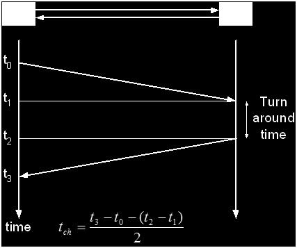
33 Communications Channel Delay
34 Concept of Current Differential Calculation
35 Configuration of GPS synchronous line current differential relay

36 Communications system based on current network technology

37 Communications system based on future network technology
38 Application Requirements Multi-terminal Line Protection Dual Breaker Applications Setting considerations Open CT Conditions CT ratio compensation Mutually coupled lines Charging current compensation Switch-onto fault Weak Infeed Issues
39 Application Requirements Out-of-step CT saturation detection / compensation Stub bus Single phase tripping Multi-phase autoreclosing Series compensated lines Shunt reactors In-zone transformers and tapped loads Backup protection considerations Communications channel cutout switch
40 Mult-Terminal Line Protection For N Terminal Lines, need N-1 ports for communicating to each relay Solution to reduce complexity: set certain relays as key relays to perform differential calculations receive information from slave relays and send trip signals to slave relays Another solution is to each relay to sum its current with adjacent relay and pass on resultant sum to next relay


41 Close-in external fault for breaker and half bus configuration

42 High Resistance Fault
43 Open CT Conditions Could produce undesirable operation Some manufacturers provide open-ct logic Logic could produce alarms or block trip Important for Protection Engineer to be knowledgeable of how scheme works
44 CT Ratio Compensation and Mutually Coupled Lines Identical scaling of currents at all ends Ratio differences handled by relay Settings need to consider differences in CTs including saturation Mutual Effects do not affect line current differential protection schemes
45 Charging Current Compensation LLLLLLLLLL SSSSSS RRRRRRRRRRRR SSSSSS I L MMMMMMMMMM I R 87 CCCCCCCC LLLLLLLL CCCCCCCC LLLLLLLL 87 I c Charging current is a capacitive leakage current on the transmission line. Can be a very large current on long transmission lines or underground cable Charging current entering local terminal is not exiting the remote Can sacrifice sensitivity to internal faults in order to account for charging current Line discharging current can cause misop for external faults Modern relays have charging current compensation (require voltage measurement)
46 Series Compensated Lines LLLLLLLLLL SSSSSS RRRRRRRRRRRR SSSSSS I L X c MMMMMMMMMM I R 87 CCCCCCCC LLLLLLLL CCCCCCCC LLLLLLLL 87 Series compensation is used to alleviate transmission line loading and/or improve system stability. LCD protection is a good choice for series compensated lines. Immune to voltage inversions Alpha plane principle is tolerant to current inversions and sub-harmonic transients
47 Shunt Reactors LLLLLLLLLL SSSSSS RRRRRRRRRRRR SSSSSS I L X c MMMMMMMMMM I R I R 87 CCCCCCCC LLLLLLLL CCCCCCCC LLLLLLLL 87 Used to compensate cap reactance of long transmission lines or HV underground cable; or voltage when line is lightly loaded or open ended. Pros and cons to including or excluding from differential zone. Pro to inclusion: less complex, less wiring Con to inclusion: line protection will operate for reactor fault, charging current compensation will vary based on reactor being in our out of service Transient behavior of shunt reactors and line capacitances may require dynamic restraint for non-fundamental frequencies in diff current
48 CT Saturation Detection/Compensation Main concern is for external faults and falsely tripping One method of compensation is to decrease sensitivity Some percentage restraint current differential relays include a CT saturation detector that increases the bias
49 In-Line Transformer LLLLLLLLLL SSSSSS RRRRRRRRRRRR SSSSSS MMMMMMMMMM CCCCCCCCCCCCCCCCCCCCCCCCCCCC LLLLLLLL 87 TTTT RRRR TTTT RRRR 87 Magnitude compensation including voltage step compensation and CT ratio matching at both voltages Compensation for transformer phase shifts Zero-sequence removal in case wye winding neutral is grounded Inrush and overexcitation detection to block differential when needed Restrained differential algorithms should be mirrored at both terminals
50 Tapped Transformer LLLLLLLLLL SSSSSS RRRRRRRRRRRR SSSSSS MMMMMMMMMM 87 CCCCCCCC LLLLLLLL CCCCCCCC LLLLLLLL 87 Without measurement or communication from tapped station, line current differential can still be applied with certain considerations: Account for total load current of transformer(s) and lines Coordinate or block for low-side transformer faults Account for magnetizing inrush of transformer(s) and capacitive inrush (diff blocking, 2 nd harmonic restraining, or distance element supervision) External ground faults on high-voltage system causing zero sequence from wye grounded neutral winding (can estimate current or remove zero-sequence diff)
51 Testing and Troubleshooting
52 Loopback Testing LLLLLLLLLL SSSSSS RRRRRRRRRRRR SSSSSS MMMMMMMMMM TTTTTTTT SSSSSS CCCCCCCCCCCCCCCCCCCCCCCCCCCC LLLLLLLL 87 TTTT RRRR TTTT RRRR 87 Connecting transmit and receive ports together Least desirable (limited) Tests minimum pick up points Does not test restraint characteristic, tapped load conditions, correct end-to-end current phasing, etc. If comm channel is available, can loopback at remote terminal and confirm channel integrity
53 Local Relay Back to Back Bench Test LLLLLLLLLL SSSSSS RRRRRRRRRRRR SSSSSS MMMMMMMMMM TTTTTTTT SSSSSS 87 TTTT RRRR RRXX TTXX 87 TTTT RRRR 87 Two or more relays required Use direct fiber or through other communication medium Can be used to test simulated faults Success of testing gives sufficient confidence in relaying, but requires validating communications channel
54 Time-Synchronized End-to-End Testing LLLLLLLLLL SSSSSS GPS GPS RRRRRRRRRRRR SSSSSS MMMMMMMMMM TTTTTTTT SSSSSS TTTTTTTT SSSSSS 87 TTTT RRRR CCCCCCCCCCCCCCCCCCCCCCCCCCCC LLLLLLLL TTTT RRRR 87 Involves testing the entire protection system (except CT if current injection is used) Use GPS time synchronized three phase test sets
55 Troubleshooting an In-Service CurrentDifferential System This subclause on troubleshooting is focused on providing guidance on direction the user toward potential sources o data errors on current differential schemes.
56 Annexes Annex A Differential protection of power lines/cables based on Rogowski coil current sensors Annex B - Bibliography
57 Line Current Differential (87L) I a +I b I a I b SSSSSS AA SSSSSS BB I Local MMMMMMMMMM I Remote I Local I Remote II LLLLLLLLLL + II RRRRRRRRRRRR = 0 II LLLLLLLLLL = II RRRRRRRRRRRR kk = II RRRRRRRRRRRR II LLLLLLLLLL = 11 Ideal Blocking Point
58 QUESTIONS?
Summary Paper for C IEEE Guide for Application of Digital Line Current Differential Relays Using Digital Communication
 Summary Paper for C37.243 IEEE Guide for Application of Digital Line Current Differential Relays Using Digital Communication Participants At the time this draft was completed, the D32 Working Group had
Transformer Protection
 Transformer Protection Transformer Protection Outline Fuses Protection Example Overcurrent Protection Differential Relaying Current Matching Phase Shift Compensation Tap Changing Under Load Magnetizing
COPYRIGHTED MATERIAL. Index
 Index Note: Bold italic type refers to entries in the Table of Contents, refers to a Standard Title and Reference number and # refers to a specific standard within the buff book 91, 40, 48* 100, 8, 22*,
This webinar brought to you by The Relion Product Family Next Generation Protection and Control IEDs from ABB
 This webinar brought to you by The Relion Product Family Next Generation Protection and Control IEDs from ABB Relion. Thinking beyond the box. Designed to seamlessly consolidate functions, Relion relays
Line Protection Roy Moxley Siemens USA
 Line Protection Roy Moxley Siemens USA Unrestricted Siemens AG 2017 siemens.com/digitalgrid What is a Railroad s Biggest Asset? Rolling Stock Share-holders Relationships Shipping Contracts Employees (Engineers)
Sequence Networks p. 26 Sequence Network Connections and Voltages p. 27 Network Connections for Fault and General Unbalances p. 28 Sequence Network
 Preface p. iii Introduction and General Philosophies p. 1 Introduction p. 1 Classification of Relays p. 1 Analog/Digital/Numerical p. 2 Protective Relaying Systems and Their Design p. 2 Design Criteria
PJM Manual 07:: PJM Protection Standards Revision: 2 Effective Date: July 1, 2016
 PJM Manual 07:: PJM Protection Standards Revision: 2 Effective Date: July 1, 2016 Prepared by System Planning Division Transmission Planning Department PJM 2016 Table of Contents Table of Contents Approval...6
Power System Protection Part VII Dr.Prof.Mohammed Tawfeeq Al-Zuhairi. Differential Protection (Unit protection)
") Differential Protection (Unit protection) Differential Protection Differential protection is the best technique in protection. In this type of protection the electrical quantities entering and leaving
Differential Protection (Unit protection) Differential Protection Differential protection is the best technique in protection. In this type of protection the electrical quantities entering and leaving
Hands On Relay School Open Lecture Transformer Differential Protection Scott Cooper
 Hands On Relay School Open Lecture Transformer Differential Protection Scott Cooper Transformer Differential Protection ntroduction: Transformer differential protection schemes are ubiquitous to almost
Transformer protection IED RET 670
 Gunnar Stranne Transformer protection IED RET 670 Santiago Septiembre 5, 2006 1 Transformer protection IED RET670 2 Introduction features and applications Differential protection functions Restricted Earth
New Smart Multi-Ended Differential Solution for Power Networks. GE Grid Solutions, UK
 New Smart Multi-Ended Differential Solution for Power Networks. G. Lloyd *, Joao Jesus *, Simon Richards *, Hengxu Ha * * GE Grid Solutions, UK Abstract Line current differential protection is based on
BUS2000 Busbar Differential Protection System
 BUS2000 Busbar Differential Protection System Differential overcurrent system with percentage restraint protection 1 Typical Busbar Arrangements Single Busbar Double Busbar with Coupler Breaker and a Half
NOVEL PROTECTION SYSTEMS FOR ARC FURNACE TRANSFORMERS
 NOVEL PROTECTION SYSTEMS FOR ARC FURNACE TRANSFORMERS Ljubomir KOJOVIC Cooper Power Systems - U.S.A. Lkojovic@cooperpower.com INTRODUCTION In steel facilities that use Electric Arc Furnaces (EAFs) to manufacture
889 Advanced Generator Protection Technical Note
 GE Grid Solutions 8 Series 889 Advanced Generator Protection Technical Note GE Publication Number: GET-20056 Copyright 2017 GE Multilin Inc. Overview The Multilin 889 is part of the 8 Series platform that
PROTECTION of electricity distribution networks
 PROTECTION of electricity distribution networks Juan M. Gers and Edward J. Holmes The Institution of Electrical Engineers Contents Preface and acknowledgments x 1 Introduction 1 1.1 Basic principles of
NERC Protection Coordination Webinar Series June 9, Phil Tatro Jon Gardell
 Power Plant and Transmission System Protection Coordination GSU Phase Overcurrent (51T), GSU Ground Overcurrent (51TG), and Breaker Failure (50BF) Protection NERC Protection Coordination Webinar Series
2015 Relay School Bus Protection Mike Kockott March, 2015
 2015 Relay School Bus Protection Mike Kockott March, 2015 History of Bus Protection Circulating current differential (1900s) High impedance differential (1940s) Percentage restrained differential (1960s)
What s New in C TM -2015, IEEE Guide for Protective Relay Applications to Transmission Lines
 What s New in C37.113 TM -2015, IEEE Guide for Protective Relay Applications to Transmission Lines This paper is a product of the IEEE PSRC D36 Working Group. The working group consisted of the following
NERC Protection Coordination Webinar Series June 16, Phil Tatro Jon Gardell
 Power Plant and Transmission System Protection Coordination Phase Distance (21) and Voltage-Controlled or Voltage-Restrained Overcurrent Protection (51V) NERC Protection Coordination Webinar Series June
Earth Fault Protection
 Earth Fault Protection Course No: E03-038 Credit: 3 PDH Velimir Lackovic, Char. Eng. Continuing Education and Development, Inc. 9 Greyridge Farm Court Stony Point, NY 10980 P: (877) 322-5800 F: (877) 322-4774
Centralized busbar differential and breaker failure protection function
 Centralized busbar differential and breaker failure protection function Budapest, December 2015 Centralized busbar differential and breaker failure protection function Protecta provides two different types
Hands On Relay School Open Lecture Transformer Differential Protection Scott Cooper
 Hands On Relay School Open Lecture Transformer Differential Protection Scott Cooper Transformer Differential Protection ntroduction: Transformer differential protection schemes are ubiquitous to almost
Bus Protection Fundamentals
 Bus Protection Fundamentals Terrence Smith GE Grid Solutions 2017 Texas A&M Protective Relay Conference Bus Protection Requirements High bus fault currents due to large number of circuits connected: CT
THE ROLE OF SYNCHROPHASORS IN THE INTEGRATION OF DISTRIBUTED ENERGY RESOURCES
 THE OLE OF SYNCHOPHASOS IN THE INTEGATION OF DISTIBUTED ENEGY ESOUCES Alexander APOSTOLOV OMICON electronics - USA alex.apostolov@omicronusa.com ABSTACT The introduction of M and P class Synchrophasors
Protection of Microgrids Using Differential Relays
 1 Protection of Microgrids Using Differential Relays Manjula Dewadasa, Member, IEEE, Arindam Ghosh, Fellow, IEEE and Gerard Ledwich, Senior Member, IEEE Abstract A microgrid provides economical and reliable
A short introduction to Protection and Automation Philosophy
 Training Center A short introduction to Protection and Automation Philosophy Philippe Goossens & Cédric Moors Training Center Contents Definitions and basic concepts Differential and distance protection
System Protection and Control Subcommittee
 Power Plant and Transmission System Protection Coordination Reverse Power (32), Negative Sequence Current (46), Inadvertent Energizing (50/27), Stator Ground Fault (59GN/27TH), Generator Differential (87G),
Unit Protection Differential Relays
 Unit Protection PROF. SHAHRAM MONTASER KOUHSARI Current, pu Current, pu Protection Relays - BASICS Note on CT polarity dots Through-current: must not operate Internal fault: must operate The CT currents
Impact of transient saturation of Current Transformer during cyclic operations Analysis and Diagnosis
 1 Impact of transient saturation of Current Transformer during cyclic operations Analysis and Diagnosis BK Pandey, DGM(OS-Elect) Venkateswara Rao Bitra, Manager (EMD Simhadri) 1.0 Introduction: Current
PROTECTION SIGNALLING
 PROTECTION SIGNALLING 1 Directional Comparison Distance Protection Schemes The importance of transmission system integrity necessitates high-speed fault clearing times and highspeed auto reclosing to avoid
Protection Basics Presented by John S. Levine, P.E. Levine Lectronics and Lectric, Inc GE Consumer & Industrial Multilin
 Protection Basics Presented by John S. Levine, P.E. Levine Lectronics and Lectric, Inc. 770 565-1556 John@L-3.com 1 Protection Fundamentals By John Levine 2 Introductions Tools Outline Enervista Launchpad
Transmission Line Protection Objective. General knowledge and familiarity with transmission protection schemes
 Transmission Line Protection Objective General knowledge and familiarity with transmission protection schemes Transmission Line Protection Topics Primary/backup protection Coordination Communication-based
Modern transformer relays include a comprehensive set of protective elements to protect transformers from faults and abnormal operating conditions
 1 Transmission transformers are important links in the bulk power system. They allow transfer of power from generation centers, up to the high-voltage grid, and to bulk electric substations for distribution
RAIDK, RAIDG, RAPDK and RACIK Phase overcurrent and earth-fault protection assemblies based on single phase measuring elements
 RAIDK, RAIDG, RAPDK and RACIK Phase overcurrent and earth-fault protection assemblies based on single phase measuring elements User s Guide General Most faults in power systems can be detected by applying
Transmission Protection Overview
 Transmission Protection Overview 2017 Hands-On Relay School Daniel Henriod Schweitzer Engineering Laboratories Pullman, WA Transmission Line Protection Objective General knowledge and familiarity with
Data. Dr Murari Mohan Saha ABB AB. KTH/EH2740 Lecture 3. Data Acquisition Block. Logic. Measurement. S/H and A/D Converter. signal conditioner
 Digital Protective Relay Dr Murari Mohan Saha ABB AB KTH/EH2740 Lecture 3 Introduction to Modern Power System Protection A digital protective relay is an industrial microprocessor system operating in real
Distance Relay Response to Transformer Energization: Problems and Solutions
 1 Distance Relay Response to Transformer Energization: Problems and Solutions Joe Mooney, P.E. and Satish Samineni, Schweitzer Engineering Laboratories Abstract Modern distance relays use various filtering
Transformer Protection Principles
 Transformer Protection Principles 1. Introduction Transformers are a critical and expensive component of the power system. Due to the long lead time for repair of and replacement of transformers, a major
Shortcomings of the Low impedance Restricted Earth Fault function as applied to an Auto Transformer. Anura Perera, Paul Keller
 Shortcomings of the Low impedance Restricted Earth Fault function as applied to an Auto Transformer Anura Perera, Paul Keller System Operator - Eskom Transmission Introduction During the design phase of
Tutorial on Operating Characteristics of Microprocessor-Based Multiterminal Line Current Differential Relays
 Tutorial on Operating Characteristics of Microprocessor-Based Multiterminal Line Current Differential Relays Bogdan Kasztenny, Gabriel Benmouyal, Héctor J. Altuve, and Normann Fischer Schweitzer Engineering
Power System Fundamentals
 Power System Fundamentals Relay Applications PJM State & Member Training Dept. Objectives At the end of this presentation the Student will be able to: Describe the purpose of protective relays Identify
Transformer Protection
 Transformer Protection Nature of transformer faults TXs, being static, totally enclosed and oil immersed develop faults only rarely but consequences large. Three main classes of faults. 1) Faults in Auxiliary
NERC Protection Coordination Webinar Series July 15, Jon Gardell
 Power Plant and Transmission System Protection Coordination Reverse Power (32), Negative Sequence Current (46), Inadvertent Energizing (50/27), Stator Ground Fault (59GN/27TH), Generator Differential (87G),
Protection of a 138/34.5 kv transformer using SEL relay
 Scholars' Mine Masters Theses Student Theses and Dissertations Fall 2016 Protection of a 138/34.5 kv transformer using SEL 387-6 relay Aamani Lakkaraju Follow this and additional works at: http://scholarsmine.mst.edu/masters_theses
AUTOMATIC CALCULATION OF RELAY SETTINGS FOR A BLOCKING PILOT SCHEME
 AUTOMATIC CALCULATION OF RELAY SETTINGS FOR A BLOCKING PILOT SCHEME Donald M. MACGREGOR Electrocon Int l, Inc. USA eii@electrocon.com Venkat TIRUPATI Electrocon Int l, Inc. USA eii@electrocon.com Russell
Distributed busbar differential protection function and breaker failure protection
 Distributed busbar differential protection function and breaker failure protection Document ID: PP-13-21321 Budapest, September 2016. Distributed busbar differential protection function and breaker failure
Bus protection with a differential relay. When there is no fault, the algebraic sum of circuit currents is zero
 Bus protection with a differential relay. When there is no fault, the algebraic sum of circuit currents is zero Consider a bus and its associated circuits consisting of lines or transformers. The algebraic
Catastrophic Relay Misoperations and Successful Relay Operation
 Catastrophic Relay Misoperations and Successful Relay Operation Steve Turner (Beckwith Electric Co., Inc.) Introduction This paper provides detailed technical analysis of several catastrophic relay misoperations
Impact of Incipient Faults on Sensitive Protection
 Impact of Incipient Faults on Sensitive Protection Paper Authors: Ilia Voloh GE Grid Solutions Zhihan Xu, Ilia Voloh GE Grid Solutions Leonardo Torelli CSE-Uniserve Presented by: Tom Ernst GE Grid Solutions
1 INTRODUCTION 1.1 PRODUCT DESCRIPTION
 GEK-00682D INTRODUCTION INTRODUCTION. PRODUCT DESCRIPTION The MDP Digital Time Overcurrent Relay is a digital, microprocessor based, nondirectional overcurrent relay that protects against phase-to-phase
Analyzing the Impact of Shunt Reactor Switching Operations Based on DFR Monitoring System
 Analyzing the Impact of Shunt Reactor Switching Operations Based on DFR Monitoring System Lalit Ghatpande, SynchroGrid, College Station, Texas, 77840 Naveen Ganta, SynchroGrid, College Station, Texas,
Appendix S: PROTECTION ALTERNATIVES FOR VARIOUS GENERATOR CONFIGURATIONS
 Appendix S: PROTECTION ALTERNATIVES FOR VARIOUS GENERATOR CONFIGURATIONS S1. Standard Interconnection Methods with Typical Circuit Configuration for Single or Multiple Units Note: The protection requirements
PRC Generator Relay Loadability. Guidelines and Technical Basis Draft 4: (June 10, 2013) Page 1 of 75
 Page 1 of 75") PRC-025-1 Introduction The document, Power Plant and Transmission System Protection Coordination, published by the NERC System Protection and Control Subcommittee (SPCS) provides extensive general discussion
PRC-025-1 Introduction The document, Power Plant and Transmission System Protection Coordination, published by the NERC System Protection and Control Subcommittee (SPCS) provides extensive general discussion
System Protection and Control Seminar
 System Protection and Control Seminar Desirable Protection We want to detect a fault within 100% of the zone of protection. We want to avoid interrupting non-faulted zones of protection. We want to clear
Detecting and Managing Geomagnetically Induced Currents With Relays
 Detecting and Managing Geomagnetically Induced Currents With Relays Copyright SEL 2013 Transformer Relay Connections Voltage Current Control RTDs Transformer Protective Relay Measures differential current
Extensive LV cable network. Figure 1: Simplified SLD of the transformer and associated LV network
 Copyright 2017 ABB. All rights reserved. 1. Introduction Many distribution networks around the world have limited earth-fault current by a resistor located in the LV winding neutral point of for example
Power Plant and Transmission System Protection Coordination Fundamentals
 Power Plant and Transmission System Protection Coordination Fundamentals NERC Protection Coordination Webinar Series June 2, 2010 Jon Gardell Agenda 2 Objective Introduction to Protection Generator and
Switch-on-to-Fault Schemes in the Context of Line Relay Loadability
 Attachment C (Agenda Item 3b) Switch-on-to-Fault Schemes in the Context of Line Relay Loadability North American Electric Reliability Council A Technical Document Prepared by the System Protection and
Transmission System Phase Backup Protection
 Reliability Guideline Transmission System Phase Backup Protection NERC System Protection and Control Subcommittee Draft for Planning Committee Approval June 2011 Table of Contents 1. Introduction and Need
PRC Generator Relay Loadability. Guidelines and Technical Basis Draft 5: (August 2, 2013) Page 1 of 76
 Page 1 of 76") PRC-025-1 Introduction The document, Power Plant and Transmission System Protection Coordination, published by the NERC System Protection and Control Subcommittee (SPCS) provides extensive general discussion
PRC-025-1 Introduction The document, Power Plant and Transmission System Protection Coordination, published by the NERC System Protection and Control Subcommittee (SPCS) provides extensive general discussion
Generator Protection GENERATOR CONTROL AND PROTECTION
 Generator Protection Generator Protection Introduction Device Numbers Symmetrical Components Fault Current Behavior Generator Grounding Stator Phase Fault (87G) Field Ground Fault (64F) Stator Ground Fault
La protection sélective des réseaux électriques
 La protection sélective des réseaux électriques ULG 21. 11. 2012 The T&D grids Generation Transmission Distribution Industry The electricity network ensure an efficient supply of energy High Voltage Transformers
 Power Station Electrical Protection A 2 B 2 C 2 Neutral C.T E M L } a 2 b 2 c 2 M M M CT Restricted E/F Relay L L L TO TRIP CIRCUIT Contents 1 The Need for Protection 2 1.1 Types of Faults............................
Babak Enayati National Grid Thursday, April 17
 2014 IEEE PES Transmission & Distribution Conference & Exposition Impacts of the Distribution System Renewable Energy Resources on the Power System Protection Babak Enayati National Grid Thursday, April
MODEL POWER SYSTEM TESTING GUIDE October 25, 2006
 October 25, 2006 Document name Category MODEL POWER SYSTEM TESTING GUIDE ( ) Regional Reliability Standard ( ) Regional Criteria ( ) Policy ( ) Guideline ( x ) Report or other ( ) Charter Document date
Busbars and lines are important elements
 CHAPTER CHAPTER 23 Protection of Busbars and Lines 23.1 Busbar Protection 23.2 Protection of Lines 23.3 Time-Graded Overcurrent Protection 23.4 Differential Pilot-Wire Protection 23.5 Distance Protection
Transmission Lines and Feeders Protection Pilot wire differential relays (Device 87L) Distance protection
 Distance protection") Transmission Lines and Feeders Protection Pilot wire differential relays (Device 87L) Distance protection 133 1. Pilot wire differential relays (Device 87L) The pilot wire differential relay is a high-speed
Transmission Lines and Feeders Protection Pilot wire differential relays (Device 87L) Distance protection 133 1. Pilot wire differential relays (Device 87L) The pilot wire differential relay is a high-speed
Power System Protection. Dr. Lionel R. Orama Exclusa, PE Week 3
 Power System Protection Dr. Lionel R. Orama Exclusa, PE Week 3 Operating Principles: Electromagnetic Attraction Relays Readings-Mason Chapters & 3 Operating quantities Electromagnetic attraction Response
Improved power transformer protection using numerical relays
 Improved power transformer protection using numerical relays Bogdan Kasztenny* and Mladen Kezunovic Texas A&M University, USA Large power transformers belong to a class of very expensive and vital components
1
 Guidelines and Technical Basis Introduction The document, Power Plant and Transmission System Protection Coordination, published by the NERC System Protection and Control Subcommittee (SPCS) provides extensive
R10. IV B.Tech I Semester Regular/Supplementary Examinations, Nov/Dec SWITCH GEAR AND PROTECTION. (Electrical and Electronics Engineering)
") R10 Set No. 1 Code No: R41023 1. a) Explain how arc is initiated and sustained in a circuit breaker when the CB controls separates. b) The following data refers to a 3-phase, 50 Hz generator: emf between
R10 Set No. 1 Code No: R41023 1. a) Explain how arc is initiated and sustained in a circuit breaker when the CB controls separates. b) The following data refers to a 3-phase, 50 Hz generator: emf between
This webinar brought to you by the Relion product family Advanced protection and control IEDs from ABB
 This webinar brought to you by the Relion product family Advanced protection and control IEDs from ABB Relion. Thinking beyond the box. Designed to seamlessly consolidate functions, Relion relays are smarter,
ENOSERV 2014 Relay & Protection Training Conference Course Descriptions
 ENOSERV 2014 Relay & Protection Training Conference Course Descriptions Day 1 Generation Protection/Motor Bus Transfer Generator Protection: 4 hours This session highlights MV generator protection and
S1-3: New and re-discovered theories and practices in relay protection
 (Cheboksary, September 9-13, 27) S1-3: New and re-discovered theories and practices in relay protection Practical experience from multiterminal line differential protection installations Z. GAJIĆ, I. BRNČIĆ,
Transmission Line Applications of Directional Ground Overcurrent Relays. Working Group D24 Report to the Line Protection Subcommittee January 2014
 Transmission Line Applications of Directional Ground Overcurrent Relays Working Group D24 Report to the Line Protection Subcommittee January 2014 Working Group Members: Don Lukach (Chairman), Rick Taylor
Communication Aided Tripping. Common Methods, Schemes and Considerations
 Communication Aided Tripping Common Methods, Schemes and Considerations Presented by: Matt Horvath, P.E. March 13, 2017 Content Summary Background Purpose Methods and Mediums Schemes Considerations Application:
This webinar brought to you by the Relion product family Advanced protection and control IEDs from ABB
 This webinar brought to you by the Relion product family Advanced protection and control IEDs from ABB Relion. Thinking beyond the box. Designed to seamlessly consolidate functions, Relion relays are smarter,
ARC FLASH HAZARD ANALYSIS AND MITIGATION
 ARC FLASH HAZARD ANALYSIS AND MITIGATION J.C. Das IEEE PRESS SERIES 0N POWER ENGINEERING Mohamed E. El-Hawary, Series Editor IEEE IEEE PRESS WILEY A JOHN WILEY & SONS, INC., PUBLICATION CONTENTS Foreword
Power System Protection Where Are We Today?
 1 Power System Protection Where Are We Today? Meliha B. Selak Power System Protection & Control IEEE PES Distinguished Lecturer Program Preceding IEEE PES Vice President for Chapters melihas@ieee.org PES
Distance Protection for Distribution Feeders. Presented By: Yordan Kyosev, P.Eng. & Curtis Ruff, P.Eng.
 Distance Protection for Distribution Feeders Presented By: Yordan Kyosev, P.Eng. & Curtis Ruff, P.Eng. Why use distance protection for distribution feeders? Distance protection is mainly used for protecting
Stabilized Differential Relay SPAD 346. Product Guide
 Issued: July 1998 Status: Updated Version: D/21.03.2006 Data subject to change without notice Features Integrated three-phase differential relay, three-phase overcurrent relay and multiconfigurable earth-fault
Impacts of the Renewable Energy Resources on the Power System Protection by: Brent M. Fedele, P.E., National Grid for: 11 th Annual CNY Engineering
 Impacts of the Renewable Energy Resources on the Power System Protection by: Brent M. Fedele, P.E., National Grid for: 11 th Annual CNY Engineering Expo - Nov. 3, 2014 Index Normal Distribution System
SPAD 346 C Stabilized differential relay
 SPAD 346 C Stabilized differential relay Stabilized Differential Relay Type SPAD 346 C Features Integrated three-phase differential relay, three-phase overcurrent relay and multiconfigurable earth-fault
Protection of Electrical Networks. Christophe Prévé
 Protection of Electrical Networks Christophe Prévé This Page Intentionally Left Blank Protection of Electrical Networks This Page Intentionally Left Blank Protection of Electrical Networks Christophe Prévé
3. (a) List out the advantages and disadvantages of HRC fuse (b) Explain fuse Characteristics in detail. [8+8]
![3. (a) List out the advantages and disadvantages of HRC fuse (b) Explain fuse Characteristics in detail. [8+8]](/thumbs/77/76027701.jpg "3. (a) List out the advantages and disadvantages of HRC fuse (b) Explain fuse Characteristics in detail. [8+8]") Code No: RR320205 Set No. 1 1. (a) Explain about Bewley s Lattice diagrams and also mention the uses of these diagrams. [6+2] (b) A line of surge impedance of 400 ohms is charged from a battery of constant
Code No: RR320205 Set No. 1 1. (a) Explain about Bewley s Lattice diagrams and also mention the uses of these diagrams. [6+2] (b) A line of surge impedance of 400 ohms is charged from a battery of constant
PIPSPC. Prepared by Eng: Ahmed Safie Eldin. And. Introduction. Protection Control. Practical. System. Power
 PIPSPC Practical Introduction Power System Protection Control Practical Introduction To Power System Protection And Control Prepared by Eng: Ahmed Safie Eldin 2005 Contents POWER SYSTEMS PRINCIPALS. 1
POWER FACTOR CORRECTION. HARMONIC FILTERING. MEDIUM AND HIGH VOLTAGE SOLUTIONS.
 POWER FACTOR CORRECTION. HARMONIC FILTERING. MEDIUM AND HIGH VOLTAGE SOLUTIONS. This document may be subject to changes. Contact ARTECHE to confirm the characteristics and availability of the products
Level 6 Graduate Diploma in Engineering Electrical Energy Systems
 9210-114 Level 6 Graduate Diploma in Engineering Electrical Energy Systems Sample Paper You should have the following for this examination one answer book non-programmable calculator pen, pencil, ruler,
Optimizing HV Capacitor-Bank Design Protection & Testing
 Optimizing HV Capacitor-Bank Design Protection & Testing Benton Vandiver III ABB Inc. 71st Annual Conference for Protective Relay Engineers Texas A&M University Introduction Shunt Capacitor Bank Considerations
Optimizing HV Capacitor Bank Design, Protection, and Testing Benton Vandiver III ABB Inc.
 Optimizing HV Capacitor Bank Design, Protection, and Testing Benton Vandiver III ABB Inc. Abstract - This paper will discuss in detail a capacitor bank protection and control scheme for >100kV systems
Verifying Transformer Differential Compensation Settings
 Verifying Transformer Differential Compensation Settings Edsel Atienza and Marion Cooper Schweitzer Engineering Laboratories, Inc. Presented at the 6th International Conference on Large Power Transformers
U I. Time Overcurrent Relays. Basic equation. More or less approximates thermal fuse. » Allow coordination with fuses 9/24/2018 ECE525.
 Time Overcurrent Relays More or less approximates thermal fuse» Allow coordination with fuses Direction of Current nduced Torque Restraining Spring Reset Position Time Dial Setting Disk Basic equation
Modular multifunction generator protection
 Modular multifunction generator Page 1 Issued June 1999 Changed since July 1998 Data subject to change without notice (SE970186) Features is a modular generator that enables selection of the desired in
Application for A Sub-harmonic Protection Relay. ERLPhase Power Technologies
 Application for A Sub-harmonic Protection Relay ERLPhase Power Technologies 1 Outline Introduction System Event at Xcel Energy Event Analysis Microprocessor based relay hardware architecture Sub harmonic
Forward to the Basics: Selected Topics in Distribution Protection
 Forward to the Basics: Selected Topics in Distribution Protection Lee Underwood and David Costello Schweitzer Engineering Laboratories, Inc. Presented at the IEEE Rural Electric Power Conference Orlando,
Line Differential Protection Under Unusual System Conditions
 Line Differential Protection Under Unusual System Conditions Yiyan Xue American Electric Power Bogdan Kasztenny, Douglas Taylor, and Yu Xia Schweitzer Engineering Laboratories, Inc. Published in Line Current
Guest Reviewers. Editorial Board. Cover design. Ivan DUDURYCH Tahir LAZIMOV Murari M. SAHA
 Guest Reviewers Ivan DUDURYCH Tahir LAZIMOV Murari M. SAHA Editorial Board Piotr PIERZ art manager Mirosaw UKOWICZ, Jan IYKOWSKI, Eugeniusz ROSOOWSKI, Janusz SZAFRAN, Waldemar REBIZANT, Daniel BEJMERT
Performance Analysis of Traditional and Improved Transformer Differential Protective Relays
 Performance Analysis of Traditional and Improved Transformer Differential Protective Relays Armando Guzmán, Stan Zocholl, and Gabriel Benmouyal Schweitzer Engineering Laboratories, Inc. Hector J. Altuve
EE Lecture 14 Wed Feb 8, 2017
 EE 5223 - Lecture 14 Wed Feb 8, 2017 Ongoing List of Topics: URL: http://www.ece.mtu.edu/faculty/bamork/ee5223/index.htm Labs - EE5224 Lab 3 - begins on Tues Feb 14th Term Project - details posted. Limit
ATP modeling of internal transformer faults for relay performance testing
 Michigan Technological University Digital Commons @ Michigan Tech Dissertations, Master's Theses and Master's Reports - Open Dissertations, Master's Theses and Master's Reports 2011 ATP modeling of internal