System Protection and Control Seminar
|
|
|
- Noah Paul
- 6 years ago
- Views:
Transcription
1 System Protection and Control Seminar
2 Desirable Protection We want to detect a fault within 100% of the zone of protection. We want to avoid interrupting non-faulted zones of protection. We want to clear a fault as quickly as possible. Limit damage to equipment. Limit the impact to external customers.
3 Stand-alone Line Protection It is desirable to have instantaneous clearing over 100% of the line, but that is not attainable without a communications channel. Due to uncertainty of modeling, the stand-alone instantaneous elements can only be set for up to 90% of the line comfortably. The remaining 10 to 15% will have delayed clearing to coordinate with remote terminals. Remote Terminal
4 Stand-alone Overcurrent Protection Similar to impedance relays, overcurrent relays with a graduated operating curve may be applied. An instantaneous element may be set similar to the zone distance elements based on fault magnitudes. The final protection is delayed based on curve stacking.
5 Why Communications Aided Relaying? Stand-alone protective scheme sensitivity (tap range) is limited for low impedance (short) lines. Stand-alone schemes cannot offer instantaneous clearing over 100% of the line. There may be a need for fast fault clearing over 100% of the zone of protection. System stability requires fast clearing of out-of - zone equipment.
6 What is Pilot Relaying? A means of providing fast clearing for 100% of the zone of protection. Requires a communications channel. Power Line Carrier Leased Phone Circuit Microwave / Spread Spectrum Radio Fiber Optic Pilot Wire / Twisted Pair It is an added expense addition to stand-alone relaying systems.
7 Current Differential HCB, LCB, CPD, SPD, REL-356, DLS2000, L90, 311L, LFCB, RFL9300, etc. Local sequence filter converts terminal currents to a single ac signal that is sent to the remote terminal. Logic at each terminal compares local ac signal to received ac signal by magnitude. Signals cancel for external faults and double up for internal faults. Simple relays revert to sensitive non-directional overcurrent protection for loss of channel. Advantage: Simplicity and Fast. Does not need comparator signal to trip. Disadvantage: Requires a continuous channel to avoid an incorrect trip. Does not allow for tapped loads without additional terminals.
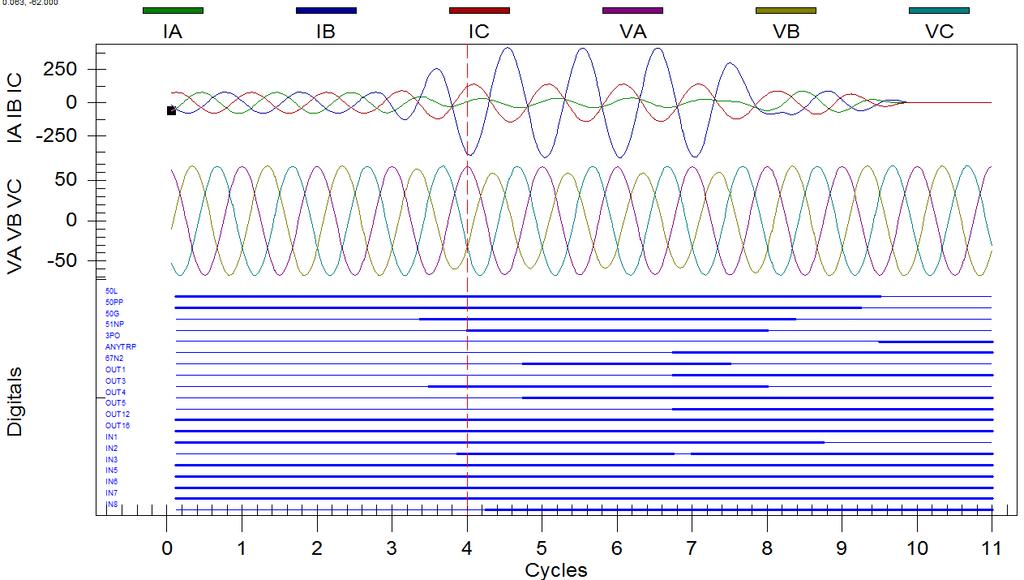
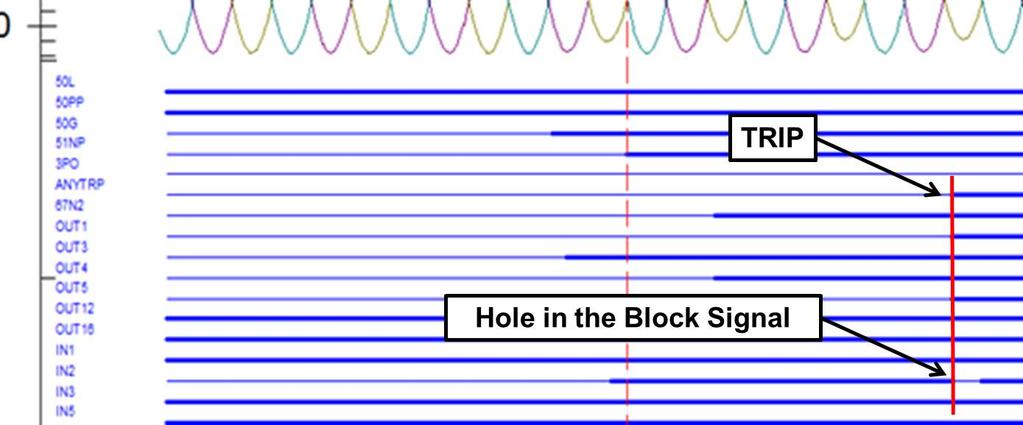
8 Phase Comparison SKBU, REL-352, REL-350, P547, SLD-21, SLD-41, etc. Local current level detectors are required to start comparison process. Local sequence filter converts terminal currents to a square wave signal that is sent to the remote terminal. Logic at each terminal compares local square wave to received square wave by phase shift. Signals form a continuous wave for external faults and is disrupted for internal faults. Relays revert to sensitive non-directional overcurrent protection for loss of channel. Advantage: Simple and (really) Fast. Can be applied to power line carrier. Can accept tapped loads within limits. Disadvantage: It will trip incorrectly if no remote signal is received. Low-side faults on tapped loads may cause a misoperation. Phase shift of the pilot signals can lead to misoperation from holes in the signal.
9 Directional Comparison Overview A Z L B System consists of: a single zone phase distance relay looking into the protected line. a single zone phase distance relay looking in reverse from the protected line. a non-directional ground overcurrent relay a directional ground relay looking into the protected line. The reverse phase relay is set greater than the over-reach of the remote forward looking relay. The non-directional ground relay is set as low as possible without nuisance keying from neutral imbalance. The directional ground relay (either overcurrent or impedance based) is set with the same pickup setting as the stand-alone directional ground (or for impedance based the same as a zone 2 element).
10 Directional Comparison Blocking Tripping Relay A B F Carrier Start Relay Tripping Relay X/0 AND Trip Carrier Start Relay 0/Y Carrier Start KDAR KD/KA/KR (KR, TC, TC-10, TC10B); CEY/CEB (CS26; CS27); most micro-processor relays; etc. Local non-directional current fault detectors are required to start carrier. Local directional relays either: Continue to key the carrier transmitter for faults in the reverse direction. Stop transmitter keying for faults in the forward direction. Advantage: Does not require carrier signal to trip. Allows tapped loads. Reliable tripping. Disadvantage: Not secure. It will over trip if the remote terminal fails to send blocking carrier. Requires random channel testing to verify working order of channel.
; microprocessor relays; etc.")


11 Directional Comparison UnBlocking KDAR KD/KA/KR, SKDU(A2B1A) (TCF, TCF-10, TCF-10B); CEY/CEB, SLYP/SLYCN(Type 50, 60, 70s); microprocessor relays; etc. Carrier guard signal is sent continuously to determine channel health. Local directional relays either: Continue to key carrier guard for faults in the reverse direction. Shift carrier signal to trip frequency for faults in the forward direction. Advantage: Reasonably secure, relative to Directional Carrier Blocking logic. Allows tapped loads. Channel is continuously monitored by guard signal. Disadvantage: Can over trip during trip permission window. Uses more frequency spectrum. Continuous radio transmission contributes to radio frequency interference.
12 Permissive Under-Reach A Z L B KD, SKD, GCY, GCX, CEY, SLY, SLYP; any microprocessor relay; etc. Can be On/Off or Frequency Shift Keying. Local terminal trips if the forward directional sensing element is picked up or direct transfer trip is received from the remote end. Local terminal sends direct transfer trip to the remote end for faults within the forward zone of protection. Advantage: Reasonably secure. Allows tapped loads. Does not require channel to trip locally for in zone forward fault. Disadvantage: Can trip by direct trip signal, accidentally. (Needs fault detector to reduce this exposure). Needs a secure channel to have 100% coverage.
13 Permissive Over-Reach A Z L B KD, SKD, GCY, GCX, CEY, SLY, SLYP; any microprocessor relay; etc. Can be On/Off or Frequency Shift Keying. Local terminal trips if the forward directional sensing element is picked up and direct transfer trip is received from the remote end. Local terminal sends direct transfer trip to the remote end for faults within the forward zone of protection. Advantage: Secure. Allows tapped loads. Disadvantage: Must have a secure and reliable channel. Can not trip without remote trip permission.
. Advantage: Fast. Allows tapped loads.")
14 Can be On/Off or Frequency Shift Keying. Local terminal trips if direct transfer trip signal is received from the remote end. Local terminal sends direct transfer trip to the remote end by local logic (Breaker Failure, AOM remote breaker, etc.). Advantage: Fast. Allows tapped loads. May be more economical than adding additional breakers. Disadvantage: Single channel applications are not secure. Requires a second transmitter/receiver to improve security and reliability. Direct Transfer Trip
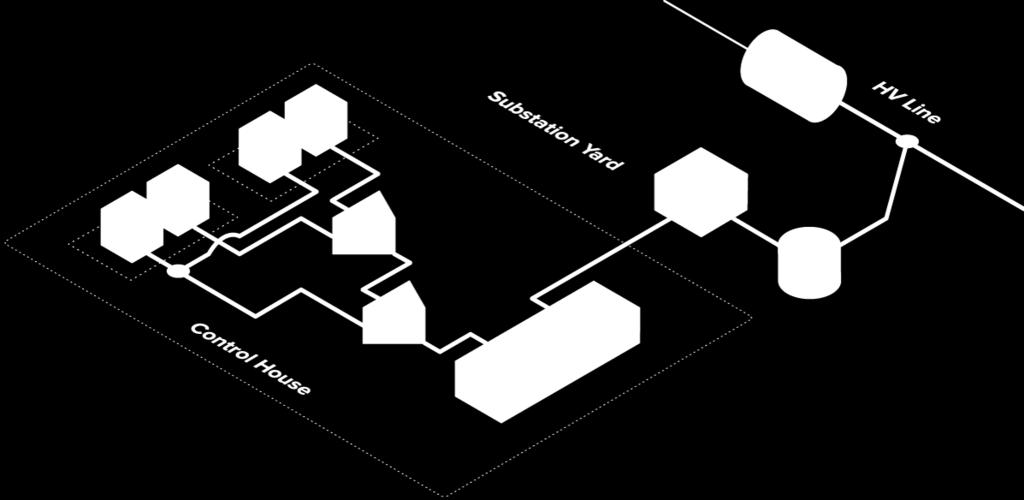
15 Power Line Coupling Network Bus Circuit Breaker Line Tuning Unit Transmitter/ Receiver Relay
16 A Field Engineer s Perspective Best Practices Jeff Brown October 2014
17 Two Things to remember about Pilot Systems! Pilot Systems give you the capability to have instantaneous tripping for 100% of the line. Pilot Systems are a balance between Speed vs. Security

18 Speed vs Security

19 Reliability APPLICATION ENGINEER COMPLIANCE ENGINEER Speed FIDVR Critical Carriers Tighter Systems Security Fewer Misops Slower trip times More Reliable

20 DCUB Guard Holes 6 msec 10 msec 6 msec 7 msec
21 DCB Misop
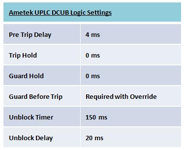
22 Reliability Timers in Radio Timers in Relay DCUB Unblock Security Timer = 20 ms DCB Block Extend =???
23 SERC Requirements
24 Best Practices 1. Mediums and Possible Errors 2. Schemes and Common Flaws 3. The Future 4. Open the Floor to Questions

25 1. Mediums

26 Power Line Carrier
27 COAX CABLE

28 Fiber Dirty connectors Tie Wraps Rodents Expensive But it is.. Secure

29 Tone Radio Vendors Bell Companies Parts, Hybrids Expensive Only available for a few more years
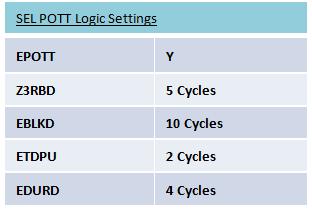
30 2. Schemes DCUB vs POTT DCB POTT (Fiber) Current Diff (Fiber)

31 Utilities get these confused? DCUB Power Line Carrier POTT Fiber Tone Microwave POTT vs. DCUB
32 Timers DCUB Timers Two places Radio or Relay
33 Timers

34 DCUB OPTION #1 Radio set up for DCUB Relay set up for POTT OPTION #2 Radio set up for POTT Relay set up for DCUB
35 How is this a problem Timers in both the relay and radio creates a conflicting race Timers missing from both relay and radio If both ends of the lines don t do it the same Tie Lines Mismatching generations
36 DCB Not as many timers! Requires Automation Local Tx s vs Remote Tx s TX = 160 khz TX = 160 khz
37 Back in the Day Radios required Crystals for the frequency New radios no Crystals Solution is TX = khz RX = khz TX = khz RX = khz

38 Fiber Scheme 1 - POTT Protocols Baud Rates Dirty Fiber Lost Packets
39 Fiber Scheme 2 Line Current Differential
40 Line Current Diff Keying DCUB or DCB does no tripping LCD is not forgiving Transfer Bus Test Switches that isolate currents Training

41 Back to the Future

42 PCM-5350 Power Communications Monitor Advanced Monitoring For Analog Channels (Power Line Carrier or Audio Tone Channels)
43 Feature Highlights 5 Channel Frequency Selective Monitoring Record Events on Changes in Frequency, Level, Reflected Power & Noise. Trend Reflected Power, Level & Noise. Real Time View Remote Access at any time via Ethernet or RS-232/485 Event Driven or Real Time Spectral Analysis of the Communication Path SOE with 32,000 Event Capacity

44 Common Configuration
45 Application Highlights Maintenance Checks with NO Outage required. Extend Maintenance Cycles with constant monitoring. Spectral Analysis synchronization with DFR s or Relay s Assist with Mis-operation evaluation and diagnosis Out of band noise Detection Alarms Verify trip frequency, levels and reflected power during event Review In Band Spectral Analysis during trip/fault occurrence for noise intrusion Monitor Adjacent Line Frequencies for Line Trap Failure Accurate Reflected Power Measurements.
46
47

48 Questions?
Transmission Line Protection Objective. General knowledge and familiarity with transmission protection schemes
 Transmission Line Protection Objective General knowledge and familiarity with transmission protection schemes Transmission Line Protection Topics Primary/backup protection Coordination Communication-based
PROTECTION SIGNALLING
 PROTECTION SIGNALLING 1 Directional Comparison Distance Protection Schemes The importance of transmission system integrity necessitates high-speed fault clearing times and highspeed auto reclosing to avoid
Relay Communication Misoperations. Southwest Power Pool System Protection and Control Working Group
 Relay Communication Misoperations Southwest Power Pool System Protection and Control Working Group Relay Misoperations The fundamental objective of power system protection schemes is to quickly provide
Transmission Protection Overview
 Transmission Protection Overview 2017 Hands-On Relay School Daniel Henriod Schweitzer Engineering Laboratories Pullman, WA Transmission Line Protection Objective General knowledge and familiarity with
Communication Aided Tripping. Common Methods, Schemes and Considerations
 Communication Aided Tripping Common Methods, Schemes and Considerations Presented by: Matt Horvath, P.E. March 13, 2017 Content Summary Background Purpose Methods and Mediums Schemes Considerations Application:
Power System Protection. Dr. Lionel R. Orama Exclusa, PE Week 9
 Power System Protection Dr. Lionel R. Orama Exclusa, PE Week 9 Pilot Relaying Communication channels & signals Pilot wire schemes Opposed voltage Circulating current Blocking schemes Directional comparison
Protective Relaying Philosophy and Design Guidelines. PJM Relay Subcommittee
 PJM Relay Subcommittee July 12, 2018 Contents SECTION 1: Introduction... 1 SECTION 2: Protective Relaying Philosophy... 2 SECTION 3: Generator Protection... 4 SECTION 4: Unit Power Transformer and Lead
This webinar brought to you by the Relion product family Advanced protection and control IEDs from ABB
 This webinar brought to you by the Relion product family Advanced protection and control IEDs from ABB Relion. Thinking beyond the box. Designed to seamlessly consolidate functions, Relion relays are smarter,
NERC Protection Coordination Webinar Series June 9, Phil Tatro Jon Gardell
 Power Plant and Transmission System Protection Coordination GSU Phase Overcurrent (51T), GSU Ground Overcurrent (51TG), and Breaker Failure (50BF) Protection NERC Protection Coordination Webinar Series
Suggested reading for this discussion includes the following SEL technical papers:
 Communications schemes for protection and control applications are essential to the efficient and reliable operation of modern electric power systems. Communications systems for power system protection
Appendix S: PROTECTION ALTERNATIVES FOR VARIOUS GENERATOR CONFIGURATIONS
 Appendix S: PROTECTION ALTERNATIVES FOR VARIOUS GENERATOR CONFIGURATIONS S1. Standard Interconnection Methods with Typical Circuit Configuration for Single or Multiple Units Note: The protection requirements
SEL-311C TRANSMISSION PROTECTION SYSTEM
 SEL-3C TRANSMISSION PROTECTION SYSTEM ADVANCED TRANSMISSION LINE PROTECTION, AUTOMATION, AND CONTROL Bus ANSI NUMBERS/ACRONYMS AND FUNCTIONS 52 3 3 2 P G 8 O U 27 68 50BF 67 P G Q 50 P G Q 59 P G Q 5 P
Protection Basics Presented by John S. Levine, P.E. Levine Lectronics and Lectric, Inc GE Consumer & Industrial Multilin
 Protection Basics Presented by John S. Levine, P.E. Levine Lectronics and Lectric, Inc. 770 565-1556 John@L-3.com 1 Protection Fundamentals By John Levine 2 Introductions Tools Outline Enervista Launchpad
Data. Dr Murari Mohan Saha ABB AB. KTH/EH2740 Lecture 3. Data Acquisition Block. Logic. Measurement. S/H and A/D Converter. signal conditioner
 Digital Protective Relay Dr Murari Mohan Saha ABB AB KTH/EH2740 Lecture 3 Introduction to Modern Power System Protection A digital protective relay is an industrial microprocessor system operating in real
Figure 1 System One Line
 Fault Coverage of Memory Polarized Mho Elements with Time Delays Hulme, Jason Abstract This paper analyzes the effect of time delays on the fault resistance coverage of memory polarized distance elements.
This webinar brought to you by The Relion Product Family Next Generation Protection and Control IEDs from ABB
 This webinar brought to you by The Relion Product Family Next Generation Protection and Control IEDs from ABB Relion. Thinking beyond the box. Designed to seamlessly consolidate functions, Relion relays
6CARRIER-CURRENT-PILOT AND MICROWAVE-PILOT RELAYS
 6CARRIER-CURRENT-PILOT AND MICROWAVE-PILOT RELAYS Chapter 5 introduced the subject of pilot relaying, gave the fundamental principles involved, and described some typical wire-pilot relaying equipments.
Busbars and lines are important elements
 CHAPTER CHAPTER 23 Protection of Busbars and Lines 23.1 Busbar Protection 23.2 Protection of Lines 23.3 Time-Graded Overcurrent Protection 23.4 Differential Pilot-Wire Protection 23.5 Distance Protection
Agenda Notes for 4 th Meeting of Sub Group in respect of Preparation of Reliability Standards for Protection System and Communication System
 Agenda Notes for 4 th Meeting of Sub Group in respect of Preparation of Reliability Standards for Protection System and Communication System Meeting Date: 27.03.2017 Time: 1430 Hrs Venue: NRPC Conference
1 INTRODUCTION 1.1 PRODUCT DESCRIPTION
 GEK-00682D INTRODUCTION INTRODUCTION. PRODUCT DESCRIPTION The MDP Digital Time Overcurrent Relay is a digital, microprocessor based, nondirectional overcurrent relay that protects against phase-to-phase
Power System Fundamentals
 Power System Fundamentals Relay Applications PJM State & Member Training Dept. Objectives At the end of this presentation the Student will be able to: Describe the purpose of protective relays Identify
APPLICATION OF A SINGLE POLE PROTECTION SCHEME TO A DOUBLE-CIRCUIT 230 KV TRANSMISSION LINE
 APPLICATION OF A SINGLE POLE PROTECTION SCHEME TO A DOUBLE-CIRCUIT 230 KV TRANSMISSION LINE By Barry W. Jackson Duke Energy Martin Best Duke Engineering & Services Ronald H. Bergen RFL Electronics Presented
Power systems Protection course
 Al-Balqa Applied University Power systems Protection course Department of Electrical Energy Engineering 1 Part 5 Relays 2 3 Relay Is a device which receive a signal from the power system thought CT and
Commercial Deployments of Line Current Differential Protection (LCDP) Using Broadband Power Line Carrier (B-PLC) Technology
 Using Broadband Power Line Carrier (B-PLC) Technology") Commercial Deployments of Line Current Differential Protection (LCDP) Using Broadband Power Line Carrier (B-PLC) Technology Nachum Sadan - Amperion Inc. Abstract Line current differential protection (LCDP)
Commercial Deployments of Line Current Differential Protection (LCDP) Using Broadband Power Line Carrier (B-PLC) Technology Nachum Sadan - Amperion Inc. Abstract Line current differential protection (LCDP)
SOLUTIONS FOR AN EVOLVING WORLD RFL Programmable FSK Powerline carrier system
 SOLUTIONS FOR AN EVOLVING WORLD RFL 9780 Programmable FSK Powerline carrier system Your world is changing and so are we. At RFL, we know your needs change much faster than your infrastructure. Our comprehensive
Protection Challenges for Transmission Lines with Long Taps
 Protection Challenges for Transmission Lines with Long Taps Jenny Patten, Majida Malki, Quanta Technology, Matt Jones, American Transmission Co. Abstract Tapped transmission lines are quite common as they
Summary Paper for C IEEE Guide for Application of Digital Line Current Differential Relays Using Digital Communication
 Summary Paper for C37.243 IEEE Guide for Application of Digital Line Current Differential Relays Using Digital Communication Participants At the time this draft was completed, the D32 Working Group had
Summary Paper for C IEEE Guide for Application of Digital Line Current Differential Relays Using Digital Communication
 Summary Paper for C37.243 IEEE Guide for Application of Digital Line Current Differential Relays Using Digital Communication by: Neftaly Torres, P.E. 70 th Annual Conference for Protective Relay Engineers,
Hands On Relay School 2017
 Hands On Relay School 2017 RFL Electronics Inc. www.rflelect.com PLC Teleprotection 2 Application of TPS PLC IEEE Std 643 2004 The PLC uses the Power lines to transmit and receive signals from station
FIBER OPTIC COMMUNICATIONS FOR UTILITY SYSTEMS
 FIBER OPTIC COMMUNICATIONS FOR UTILITY SYSTEMS Technical Publication F045-P0195 By Roger E. Ray AMETEK Power Instruments 4050 NW 121st Avenue Coral Springs, FL USA 33065 1 954-344-9822 www.pulsartech.com
Reducing the Effects of Short Circuit Faults on Sensitive Loads in Distribution Systems
 Reducing the Effects of Short Circuit Faults on Sensitive Loads in Distribution Systems Alexander Apostolov AREVA T&D Automation I. INTRODUCTION The electric utilities industry is going through significant
System Protection and Control Subcommittee
 Power Plant and Transmission System Protection Coordination Reverse Power (32), Negative Sequence Current (46), Inadvertent Energizing (50/27), Stator Ground Fault (59GN/27TH), Generator Differential (87G),
No. SSIEC-PRC SHINSUNG. Polymer Recloser SIREC SERIES 15kV, 27kV, 38kV 400A, 630A, 800A
 No. SSIEC-PRC-00803-1 SHINSUNG Polymer Recloser SIREC SERIES 15kV, 27kV, 38kV 400A, 630A, 800A Introduction SIREC(Solid Insulated Recloser) is designed for outdoor application with lightweight, longlife,
High-Speed Distribution Protection Made Easy: Communications-Assisted Protection Schemes for Distribution Applications
 High-Speed Distribution Protection Made Easy: Communications-Assisted Protection Schemes for Distribution Applications Roy Moxley and Ken Fodero Schweitzer Engineering Laboratories, Inc. Published in the
2015 Relay School Bus Protection Mike Kockott March, 2015
 2015 Relay School Bus Protection Mike Kockott March, 2015 History of Bus Protection Circulating current differential (1900s) High impedance differential (1940s) Percentage restrained differential (1960s)
NERC Protection Coordination Webinar Series July 15, Jon Gardell
 Power Plant and Transmission System Protection Coordination Reverse Power (32), Negative Sequence Current (46), Inadvertent Energizing (50/27), Stator Ground Fault (59GN/27TH), Generator Differential (87G),
PJM Manual 07:: PJM Protection Standards Revision: 2 Effective Date: July 1, 2016
 PJM Manual 07:: PJM Protection Standards Revision: 2 Effective Date: July 1, 2016 Prepared by System Planning Division Transmission Planning Department PJM 2016 Table of Contents Table of Contents Approval...6
BUS2000 Busbar Differential Protection System
 BUS2000 Busbar Differential Protection System Differential overcurrent system with percentage restraint protection 1 Typical Busbar Arrangements Single Busbar Double Busbar with Coupler Breaker and a Half
EE 741 Spring Electric Power Distribution Systems An Overview
 EE 741 Spring 2017 Electric Power Distribution Systems An Overview Basic Power System Layout There are over 100 substations in the Las Vegas Valley pic of closest substation Substation Design Substation
THE ADVANTAGES OF CONTINUOUS MONITORING OF POWER LINE CARRIER (PLC) CHANNELS APPLIED TO PROTECTION SYSTEMS
 CHANNELS APPLIED TO PROTECTION SYSTEMS") THE ADVANTAGES OF CONTINUOUS MONITORING OF POWER LINE CARRIER (PLC) CHANNELS APPLIED TO PROTECTION SYSTEMS Roger Ray, Alan Jayson & Ray Fella, PowerComm Solutions, LLC, Jeffrey E Brown, Georgia Transmission;
THE ADVANTAGES OF CONTINUOUS MONITORING OF POWER LINE CARRIER (PLC) CHANNELS APPLIED TO PROTECTION SYSTEMS Roger Ray, Alan Jayson & Ray Fella, PowerComm Solutions, LLC, Jeffrey E Brown, Georgia Transmission;
Distance Protection for Distribution Feeders. Presented By: Yordan Kyosev, P.Eng. & Curtis Ruff, P.Eng.
 Distance Protection for Distribution Feeders Presented By: Yordan Kyosev, P.Eng. & Curtis Ruff, P.Eng. Why use distance protection for distribution feeders? Distance protection is mainly used for protecting
Switch-on-to-Fault Schemes in the Context of Line Relay Loadability
 Attachment C (Agenda Item 3b) Switch-on-to-Fault Schemes in the Context of Line Relay Loadability North American Electric Reliability Council A Technical Document Prepared by the System Protection and
U I. Time Overcurrent Relays. Basic equation. More or less approximates thermal fuse. » Allow coordination with fuses 9/24/2018 ECE525.
 Time Overcurrent Relays More or less approximates thermal fuse» Allow coordination with fuses Direction of Current nduced Torque Restraining Spring Reset Position Time Dial Setting Disk Basic equation
COPYRIGHTED MATERIAL. Index
 Index Note: Bold italic type refers to entries in the Table of Contents, refers to a Standard Title and Reference number and # refers to a specific standard within the buff book 91, 40, 48* 100, 8, 22*,
PD300. Transformer, generator and motor protection Data sheet
 PD300 Transformer, generator and motor protection Data sheet DSE_PD300_eng_AO No part of this publication may be reproduced by whatever means without the prior written permission of Ingeteam T&D. One of
REB500 TESTING PROCEDURES
 Activate HMI 500/REBWIN ver 6.10 or 7.xx. The following screen will appear. Check out the Read Only box & type the password System. Click ok. Connect the black communication cable from the Com port until
Using a Multiple Analog Input Distance Relay as a DFR
 Using a Multiple Analog Input Distance Relay as a DFR Dennis Denison Senior Transmission Specialist Entergy Rich Hunt, M.S., P.E. Senior Field Application Engineer NxtPhase T&D Corporation Presented at
TESTING PROCEDURE for SEL 311L DISTANCE and DIFFERENTIAL RELAY
 1 TESTING PROCEDURE for SEL 311L DISTANCE and DIFFERENTIAL RELAY 2 CONTENTS 1. Launching COMMUNICATION and GETTING Setting Parameters from RELAY 2. MEASUREMENT 3. DIFFERENTIAL TEST 4. OVERCURRENT TEST
Arizona Public Service Company and the Transmission Partnership for National Electric Power Company of Jordan
 Arizona Public Service Company and the Transmission Partnership for National Electric Power Company of Jordan Mark Hackney October 5-8, 2009 Amman, Jordan Energy Control Center Layout 2 Energy Control
This is by far the most ideal method, but poses some logistical problems:
 NXU to Help Migrate to New Radio System Purpose This Application Note will describe a method at which NXU Network extension Units can aid in the migration from a legacy radio system to a new, or different
NERC Protection Coordination Webinar Series June 16, Phil Tatro Jon Gardell
 Power Plant and Transmission System Protection Coordination Phase Distance (21) and Voltage-Controlled or Voltage-Restrained Overcurrent Protection (51V) NERC Protection Coordination Webinar Series June
PTR-1500 AUDIO TONE TELEPROTECTION TERMINAL FEATURES DESCRIPTION
 PTR-1500 AUDIO TONE TELEPROTECTION TERMINAL FEATURES Up to four channels per unit Full on-board programmability Available pilot tone channel Single end manual and automatic testing Modular design Audio
DIFFERENTIAL CURRENT GENERATOR «POCDIF» (AC/DC - 32A - 50V - 12 ranges)
") PERFORMANCES 12 ranges of AC current from 16 ma to 128 A peak AC permanent current up to 26 ARMS Nine ranges of DC permanent current from 16 ma to 12 A DC current ± 6mA or ± 10 ma stackable to AC current
PERFORMANCES 12 ranges of AC current from 16 ma to 128 A peak AC permanent current up to 26 ARMS Nine ranges of DC permanent current from 16 ma to 12 A DC current ± 6mA or ± 10 ma stackable to AC current
Transmission System Phase Backup Protection
 Reliability Guideline Transmission System Phase Backup Protection NERC System Protection and Control Subcommittee Draft for Planning Committee Approval June 2011 Table of Contents 1. Introduction and Need
USING RS-232 to RS-485 CONVERTERS (With RS-232, RS-422 and RS-485 devices)
") ICS DataCom Application Note USING RS- to RS- CONVERTERS (With RS-, RS- and RS- devices) INTRODUCTION Table RS-/RS- Logic Levels This application note provides information about using ICSDataCom's RS-
ICS DataCom Application Note USING RS- to RS- CONVERTERS (With RS-, RS- and RS- devices) INTRODUCTION Table RS-/RS- Logic Levels This application note provides information about using ICSDataCom's RS-
SPECIAL SPECIFICATION 6744 Spread Spectrum Radio
 2004 Specifications CSJ 0924-06-244 SPECIAL SPECIFICATION 6744 Spread Spectrum Radio 1. Description. Furnish and install spread spectrum radio system. 2. Materials. Supply complete manufacturer specifications
Speed and Security Considerations for Protection Channels
 Speed and Security Considerations for Protection Channels Shankar V. Achanta, Ryan Bradetich, and Ken Fodero Schweitzer Engineering Laboratories, Inc. 2016 IEEE. Personal use of this material is permitted.
CARRIER-AIDED PROTECTION OF TRANSMISSION LINES
 CARRIER-AIDED PROTECTION OF TRANSMISSION LINES Need for Carrier-aided Protection Fault statistics Typical de-ionization times Only 60% of line length in the middle gets high speed protection from both
(Circuits Subject to Requirements R1 R5) Generator Owner with load-responsive phase protection systems as described in
 Generator Owner with load-responsive phase protection systems as described in") A. Introduction 1. Title: Transmission Relay Loadability 2. Number: PRC-023-3 3. Purpose: Protective relay settings shall not limit transmission loadability; not interfere with system operators ability
A. Introduction 1. Title: Transmission Relay Loadability 2. Number: PRC-023-3 3. Purpose: Protective relay settings shall not limit transmission loadability; not interfere with system operators ability
PROTECTIVE RELAYING & COMMUNICATIONS
 PROTECTIVE RELAYING & COMMUNICATIONS TOPICS The Power System Components Protection Principles Protection System Components 2 TOPOLOGY OF TYPICAL POWER SYSTEM 3 POWER SYSTEM COMPONENTS Generators (Alternators)
Protection & Control Challenges with Distributed Generation
 2015 Hydro One. All rights reserved. Operating Effectiveness Hydro One Networks Inc Protection & Control Challenges with Distributed Generation Pankaj Sharma, P Eng. Grid Operations Manager Operating Effectiveness
Phase Comparison Relaying
 MULTILIN GER-2681B GE Power Management Phase Comparison Relaying PHASE COMPARISON RELAYING INTRODUCTION Phase comparison relaying is a kind of differential relaying that compares the phase angles of the
Line Protection Roy Moxley Siemens USA
 Line Protection Roy Moxley Siemens USA Unrestricted Siemens AG 2017 siemens.com/digitalgrid What is a Railroad s Biggest Asset? Rolling Stock Share-holders Relationships Shipping Contracts Employees (Engineers)
What s New in C TM -2015, IEEE Guide for Protective Relay Applications to Transmission Lines
 What s New in C37.113 TM -2015, IEEE Guide for Protective Relay Applications to Transmission Lines This paper is a product of the IEEE PSRC D36 Working Group. The working group consisted of the following
Relaying 101. by: Tom Ernst GE Grid Solutions
 Relaying 101 by: Tom Ernst GE Grid Solutions Thomas.ernst@ge.com Relaying 101 The abridged edition Too Much to Cover Power system theory review Phasor domain representation of sinusoidal waveforms 1-phase
Module 9. Fault Type Form 4.X RELIABILITY ACCOUNTABILITY
 Module 9 Fault Type Form 4.X 1 M9 Fault Type The descriptor of the fault, if any, associated with each Automatic Outage of an Element. 1. No fault 2. Phase-to-phase fault (P-P) 3. Single phase-to-ground
Bus Protection Fundamentals
 Bus Protection Fundamentals Terrence Smith GE Grid Solutions 2017 Texas A&M Protective Relay Conference Bus Protection Requirements High bus fault currents due to large number of circuits connected: CT
www. ElectricalPartManuals. com Transformer Differential Relay MD32T Transformer Differential Relay
 Transformer Differential Relay The MD3T Transformer Differential Relay is a member of Cooper Power Systems Edison line of microprocessor based protective relays. The MD3T relay offers the following functions:
Transformer Protection
 Transformer Protection Transformer Protection Outline Fuses Protection Example Overcurrent Protection Differential Relaying Current Matching Phase Shift Compensation Tap Changing Under Load Magnetizing
Communications Assisted Islanding Detection
 Communications Assisted Islanding Detection Contrasting Direct Transfer Trip and Methods Brian Dob and Craig Palmer Hubbell Power Systems, Inc. Boonton Twp NJ, USA Abstract A power system island is a part
Power Monitoring in Multicarrier systems
 Power Monitoring in Multicarrier systems It is the responsibility of the engineer to fully understand the hardware used in their design and reduce the risk of not delivering the requirements included in
No. SSIEC-SEW SHINSUNG. Solid Insulation Eco Load Break Switch (SILO) SILO SERIES 15kV, 27kV 400A, 630A
 SILO SERIES 15kV, 27kV 400A, 630A") SHINSUNG Solid Insulation Eco Load Break Switch (SILO) SILO SERIES 15kV, 27kV 400A, 630A Enhanced Self Healing System General SILO is 3 phase, solid insulated load break switch (LBS) and vacuum interruption
SHINSUNG Solid Insulation Eco Load Break Switch (SILO) SILO SERIES 15kV, 27kV 400A, 630A Enhanced Self Healing System General SILO is 3 phase, solid insulated load break switch (LBS) and vacuum interruption
www. ElectricalPartManuals. com Generator Differential Relay MD32G Rotating Machine Differential Relay
 Generator Differential Relay The MD3G Rotating Machine Differential Relay is a member of Cooper Power Systems Edison line of microprocessor based protective relays. The MD3G relay offers the following
Protecting Large Machines for Arcing Faults
 Protecting Large Machines for Arcing Faults March 2, 2010 INTRODUCTION Arcing faults occur due to dirty insulators or broken strands in the stator windings. Such faults if undetected can lead to overheating
Sequence Networks p. 26 Sequence Network Connections and Voltages p. 27 Network Connections for Fault and General Unbalances p. 28 Sequence Network
 Preface p. iii Introduction and General Philosophies p. 1 Introduction p. 1 Classification of Relays p. 1 Analog/Digital/Numerical p. 2 Protective Relaying Systems and Their Design p. 2 Design Criteria
Setting Generic Distance Relay UTP-100#WPSC1. in the. Computer-Aided Protection Engineering System (CAPE)
") Setting Generic Distance Relay UTP-100#WPSC1 in the Computer-Aided Protection Engineering System (CAPE) Prepared for CAPE Users' Group August 6, 1998 Revised August 24, 1998 Electrocon International, Inc.
Setting Generic Distance Relay UTP-100#WPSC1 in the Computer-Aided Protection Engineering System (CAPE) Prepared for CAPE Users' Group August 6, 1998 Revised August 24, 1998 Electrocon International, Inc.
ARC FLASH PPE GUIDELINES FOR INDUSTRIAL POWER SYSTEMS
 The Electrical Power Engineers Qual-Tech Engineers, Inc. 201 Johnson Road Building #1 Suite 203 Houston, PA 15342-1300 Phone 724-873-9275 Fax 724-873-8910 www.qualtecheng.com ARC FLASH PPE GUIDELINES FOR
Standard Development Timeline
 Standard Development Timeline This section is maintained by the drafting team during the development of the standard and will be removed when the standard is adopted by the Board of Trustees. Description
O V E R V I E W O F T H E
 A CABLE Technicians TESTING Approach to Generator STANDARDS: Protection O V E R V I E W O F T H E 1 Moderator n Ron Spataro AVO Training Institute Marketing Manager 2 Q&A n Send us your questions and comments
SOLUTIONS FOR AN EVOLVING WORLD RFL DSP Powerline Carrier System
 SOLUTIONS FOR AN EVOLVING WORLD RFL 9508 DSP Powerline Carrier System Your world is changing and so are we. At RFL, we know your needs change much faster than your infrastructure. Our comprehensive line
Home & Building Automation. parte 2
 Home & Building Automation parte 2 Corso di reti per l automazione industriale Prof. Orazio Mirabella Technologies for Home automation Main distribution 230V TP (Twisted Pair) Socket Lighting Sun blinds
UNIT-4 POWER QUALITY MONITORING
 UNIT-4 POWER QUALITY MONITORING Terms and Definitions Spectrum analyzer Swept heterodyne technique FFT (or) digital technique tracking generator harmonic analyzer An instrument used for the analysis and
Distribution Automation Smart Feeders in a Smart Grid World Quanta Technology LLC
 Distribution Automation Smart Feeders in a Smart Grid World DA Communications Telecommunications Services This diagram depicts the typical telecommunications services used to interconnect a Utility s customers,
EE Lecture 14 Wed Feb 8, 2017
 EE 5223 - Lecture 14 Wed Feb 8, 2017 Ongoing List of Topics: URL: http://www.ece.mtu.edu/faculty/bamork/ee5223/index.htm Labs - EE5224 Lab 3 - begins on Tues Feb 14th Term Project - details posted. Limit
 Power Station Electrical Protection A 2 B 2 C 2 Neutral C.T E M L } a 2 b 2 c 2 M M M CT Restricted E/F Relay L L L TO TRIP CIRCUIT Contents 1 The Need for Protection 2 1.1 Types of Faults............................
8902/RE and 8902/RR Resolver Speed Feedback Options
 8902/RE and 8902/RR Resolver Speed Feedback Options Technical Manual HA469251U002 Issue 1 Compatible with Version 2.x and 3.x Software Copyright 2009 Parker SSD Drives, a division of Parker Hannifin Ltd.
THE ROLE OF SYNCHROPHASORS IN THE INTEGRATION OF DISTRIBUTED ENERGY RESOURCES
 THE OLE OF SYNCHOPHASOS IN THE INTEGATION OF DISTIBUTED ENEGY ESOUCES Alexander APOSTOLOV OMICON electronics - USA alex.apostolov@omicronusa.com ABSTACT The introduction of M and P class Synchrophasors
Digital Line Protection System
 Digital Line Protection System! Microprocessor Based Protection, Control and Monitoring System! Waveform Sampling! Proven Protection! Economical! Ease of Retrofit 1 DLP-D D Enhancements ASCII SUBSET Three
Type REL 350 High-Speed Segregated Phase Comparison Line Protection System
 A Automation Inc Descriptive ulletin Substation and Automation Division 41-461M Coral Springs, FL Allentown, PA September 2000 Device Number: 78 For Phase and Ground Fault Protection of Transmission Lines
Use of Voter Comparators to Improve Railroad Radio Communications
 Use of Voter Comparators to Improve Railroad Radio Communications Purpose This Application Note will describe the use of the SNV-12 Voter Comparator to expand radio coverage in railroad applications. Introduction
Model 4xx. Plug-in Series Of FSK Modems USER GUIDE. (TI) 20 Jan 06 DWG: A GDI COMMUNICATIONS LLC PO Box I-80 Exit 1 Verdi, NV 89439
 20 Jan 06 DWG: A GDI COMMUNICATIONS LLC PO Box I-80 Exit 1 Verdi, NV 89439") Model 4xx Plug-in Series Of FSK s USER GUIDE (TI) 20 Jan 06 DWG: A01164 GDI COMMUNICATIONS LLC PO Box 1330 280 I-80 Exit 1 Verdi, NV 89439 Phone: (775) 345-8000 Fax: (775) 345-8010 Web: www.sgdi.com Email:
Model 4xx Plug-in Series Of FSK s USER GUIDE (TI) 20 Jan 06 DWG: A01164 GDI COMMUNICATIONS LLC PO Box 1330 280 I-80 Exit 1 Verdi, NV 89439 Phone: (775) 345-8000 Fax: (775) 345-8010 Web: www.sgdi.com Email:
Protection of Microgrids Using Differential Relays
 1 Protection of Microgrids Using Differential Relays Manjula Dewadasa, Member, IEEE, Arindam Ghosh, Fellow, IEEE and Gerard Ledwich, Senior Member, IEEE Abstract A microgrid provides economical and reliable
PLAN... RESPOND... RESTORE! Utility Automation & Information Technology... Automation Rising
 Automation Rising Q U A R T E R LY First Quarter 2013 The Digital Magazine of Automation & Information Technology for Electric, Gas and Water Utilities Utility Automation & Information Technology... PLAN...
Shortcomings of the Low impedance Restricted Earth Fault function as applied to an Auto Transformer. Anura Perera, Paul Keller
 Shortcomings of the Low impedance Restricted Earth Fault function as applied to an Auto Transformer Anura Perera, Paul Keller System Operator - Eskom Transmission Introduction During the design phase of
Moxa ICF-1280I Series Industrial PROFIBUS-to-Fiber Converter
 Moxa ICF-1280I Series Industrial PROFIBUS-to-Fiber Converter Hardware Installation Guide First Edition, August 2013 2013 Moxa Inc. All rights reserved. P/N: 1802012800011 Introduction The ICF-1280I series
Smart Grid Smarter Protection: Lessons Learned
 1 Smart Grid Smarter Protection: Lessons Learned Kevin Damron and Randy Spacek Avista Utilities Abstract Avista embarked on a smart grid initiative through grants provided by the Department of Energy (DOE)
A New Use for Fault Indicators SEL Revolutionizes Distribution System Protection. Steve T. Watt, Shankar V. Achanta, and Peter Selejan
 A New Use for Fault Indicators SEL Revolutionizes Distribution System Protection Steve T. Watt, Shankar V. Achanta, and Peter Selejan 2017 by Schweitzer Engineering Laboratories, Inc. All rights reserved.
 UNIT I FUNDAMENTALS OF ANALOG COMMUNICATION Introduction In the Microbroadcasting services, a reliable radio communication system is of vital importance. The swiftly moving operations of modern communities
Optimizing HV Capacitor Bank Design, Protection, and Testing Benton Vandiver III ABB Inc.
 Optimizing HV Capacitor Bank Design, Protection, and Testing Benton Vandiver III ABB Inc. Abstract - This paper will discuss in detail a capacitor bank protection and control scheme for >100kV systems
Power Plant and Transmission System Protection Coordination
 Agenda Item 5.h Attachment 1 A Technical Reference Document Power Plant and Transmission System Protection Coordination Draft 6.9 November 19, 2009 NERC System Protection and Control Subcommittee November