U I. Time Overcurrent Relays. Basic equation. More or less approximates thermal fuse. » Allow coordination with fuses 9/24/2018 ECE525.
|
|
|
- Jonas Oliver
- 5 years ago
- Views:
Transcription
1 Time Overcurrent Relays More or less approximates thermal fuse» Allow coordination with fuses Direction of Current nduced Torque Restraining Spring Reset Position Time Dial Setting Disk Basic equation Operating torque T s p Restraining Torque Kd t s = restraining spring torque = applied current p = pick up current K d = disk damping factor = angle of disk rotation (proportional to Time Dial Setting (TDS)
2 Relay Response t t K p d s t K d p s. Operating torque = Restraining Torque. ntegrate w.r.t. Time trip time K TDS p d s 3. TDS (setting angle), where triptime = t -t Relay Response 4. Finding trip time M A TDS K TDS trip time p s d Where: M = / p A = K d /t s
3 Standard Curves -- standard formats Reset Time (M < ) tr C TDS M Trip time (M ) tt TDS M A B p Some manufacturers include disk inertia in B US and EC curve parameters Curve A B C P U.S. Moderately inverse (U) U.S. nverse (U) U.S. Very inverse (U3) U.S. Extremely inverse (U4) U.S. Short-time inverse (U5) E.C. Class A - Standard inverse (C) E.C. Class B Very inverse (C) E.C. Class C Extremely inverse (C3) E.C Long-time inverse (C4) E.C Short-time inverse (C5)
")
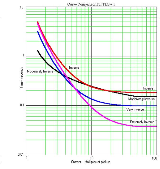
4 US nverse (U) Characteristic Comparison of curves 4
 3 3 4")
5 Extremely nverse Curve and 50E fuse Example Bus # Local Bus # Local Bus #3 Source Vs Z R Z R3 Z3 R4 Local Z4 Faulted Line Want the relay on the faulted line, R4, to be the only relay to trip Max and min fault current (based on ends of faulted line)
6 Example continued The desired coordination can be accomplished by: increasing the time dial settings as one proceeds toward the source.» f relay R is expected to provide backup protection for relay R4,» Then R4, the relay with the greatest source impedance, would be set with the lowest time dial setting Example continued» f MN is defined as the minimum fault current,» Then the pickup current must be set at or below this current but above maximum load current.» Usually with a margin around both» For relays R and R3, the TDS must be set to trip no faster then the next downstream device when the fault current is maximum for an out of zone fault 6

7 EMTP relay simulation R Bus Gen Source mpedance 30KV Xfmr S Bus Breaker 69KV Breaker 5 5 Fault # C-G Fault # C-G resistive fault is initiated at 8.3 ms and progresses to a 5 fault at 6 ms as can occur by a tree branch coming in contact with the wire. Example with a trip 7

 8")
8 Comparing relay coordination (light load) Comparing relay coordination (heavy load) 8
9 Directional Control vs Direction Supervision Reference Signal Phase Current Directional Element (3) 3 DC Bus + 3 Reference Signal Phase Current Directional Element (3) 3 DC Bus + Phase Current Overcurrent Element (50 or 5) 50/ 5 50/5 Phase Current 3 Overcurrent Element (50 or 5) 50/ 5 50/5 5 AC Circuit Breaker 5 AC Circuit Breaker a. Directional Supervision DC Bus - b. Directional Control DC Bus - Directional Step-Time Overcurrent (ANS 67) The directional overcurrent relay can be perceived as a type 50 instantaneous element controlled by a type 3 directional element f the type 67 relay element is to provide backup protection, they use definite time delay for downstream coordination The 67 element requires more attention to detail for coordination than do type 5 relays» The advantage that the stepped time has over the 5 is that the time steps are independently set.» The disadvantage is that overreach errors have a more pronounced affect that often proves difficult to coordinate 9
10 Directional Step-Time Overcurrent (ANS 67) Bus S 67 5 ncreasing time G F F F3 F Overcurrent Elements in Microprocessor Relays Expect the relay to be able to coordinate with fuses and electromechanical relays mplement relay function using the standard curve equations Use digital filters to compute RMS magnitude from measured currents Add directional supervision Take advantage of some calculations difficult to do without microprocessor 0
Time-current Coordination
 269 5.2.3.1 Time-current Coordination Time that is controlled by current magnitude permits discriminating faults at one location from another. There are three variables available to discriminate faults,
Transmission Line Protection Objective. General knowledge and familiarity with transmission protection schemes
 Transmission Line Protection Objective General knowledge and familiarity with transmission protection schemes Transmission Line Protection Topics Primary/backup protection Coordination Communication-based
1 INTRODUCTION 1.1 PRODUCT DESCRIPTION
 GEK-00682D INTRODUCTION INTRODUCTION. PRODUCT DESCRIPTION The MDP Digital Time Overcurrent Relay is a digital, microprocessor based, nondirectional overcurrent relay that protects against phase-to-phase
Protection Introduction
 1.0 Introduction Protection 2 There are five basic classes of protective relays: Magnitude relays Directional relays Ratio (impedance) relays Differential relays Pilot relays We will study each of these.
POWER SYSTEM ANALYSIS TADP 641 SETTING OF OVERCURRENT RELAYS
 POWER SYSTEM ANALYSIS TADP 641 SETTING OF OVERCURRENT RELAYS Juan Manuel Gers, PhD Protection coordination principles Relay coordination is the process of selecting settings that will assure that the relays
ARC FLASH PPE GUIDELINES FOR INDUSTRIAL POWER SYSTEMS
 The Electrical Power Engineers Qual-Tech Engineers, Inc. 201 Johnson Road Building #1 Suite 203 Houston, PA 15342-1300 Phone 724-873-9275 Fax 724-873-8910 www.qualtecheng.com ARC FLASH PPE GUIDELINES FOR
Transmission Protection Overview
 Transmission Protection Overview 2017 Hands-On Relay School Daniel Henriod Schweitzer Engineering Laboratories Pullman, WA Transmission Line Protection Objective General knowledge and familiarity with
Distance Protection for Distribution Feeders. Presented By: Yordan Kyosev, P.Eng. & Curtis Ruff, P.Eng.
 Distance Protection for Distribution Feeders Presented By: Yordan Kyosev, P.Eng. & Curtis Ruff, P.Eng. Why use distance protection for distribution feeders? Distance protection is mainly used for protecting
Generator Protection GENERATOR CONTROL AND PROTECTION
 Generator Protection Generator Protection Introduction Device Numbers Symmetrical Components Fault Current Behavior Generator Grounding Stator Phase Fault (87G) Field Ground Fault (64F) Stator Ground Fault
Transformer Protection
 Transformer Protection Transformer Protection Outline Fuses Protection Example Overcurrent Protection Differential Relaying Current Matching Phase Shift Compensation Tap Changing Under Load Magnetizing
Protective Relays Digitrip 3000
 New Information Technical Data Effective: May 1999 Page 1 Applications Provides reliable 3-phase and ground overcurrent protection for all voltage levels. Primary feeder circuit protection Primary transformer
Overcurrent Protective Relays
 Power System Protection Overcurrent Protective Relays Dr.Professor Mohammed Tawfeeq Lazim Alzuhairi 99 Power system protection Dr.Mohammed Tawfeeq Overcurrent Protective Relays Overcurrent relays Overcurrent
Protection of a 138/34.5 kv transformer using SEL relay
 Scholars' Mine Masters Theses Student Theses and Dissertations Fall 2016 Protection of a 138/34.5 kv transformer using SEL 387-6 relay Aamani Lakkaraju Follow this and additional works at: http://scholarsmine.mst.edu/masters_theses
Reducing the Effects of Short Circuit Faults on Sensitive Loads in Distribution Systems
 Reducing the Effects of Short Circuit Faults on Sensitive Loads in Distribution Systems Alexander Apostolov AREVA T&D Automation I. INTRODUCTION The electric utilities industry is going through significant
9 Overcurrent Protection for Phase and Earth Faults
 Overcurrent Protection for Phase and Earth Faults Introduction 9. Co-ordination procedure 9.2 Principles of time/current grading 9.3 Standard I.D.M.T. overcurrent relays 9.4 Combined I.D.M.T. and high
NERC Protection Coordination Webinar Series June 9, Phil Tatro Jon Gardell
 Power Plant and Transmission System Protection Coordination GSU Phase Overcurrent (51T), GSU Ground Overcurrent (51TG), and Breaker Failure (50BF) Protection NERC Protection Coordination Webinar Series
Overcurrent Elements
 Exercise Objectives Hands-On Relay Testing Session Overcurrent Elements After completing this exercise, you should be able to do the following: Identify overcurrent element settings. Determine effective
Phase and neutral overcurrent protection
 Phase and neutral overcurrent protection Page 1 ssued June 1999 Changed since July 1998 Data subject to change without notice (SE970165) Features Two-phase or three-phase time-overcurrent and earth fault
DISTRIBUTION DEVICE COORDINATION
 DISTRIBUTION DEVICE COORDINATION Kevin Damron & Calvin Howard Avista Utilities Presented March th, 08 At the 5 th Annual Hands-On Relay School Washington State University Pullman, Washington TABLE OF CONTENTS
POWER SYSTEM ANALYSIS TADP 641 SETTING EXAMPLE FOR OVERCURRENT RELAYS
 POWER SYSTEM ANALYSIS TADP 641 SETTING EXAMPLE FOR OVERCURRENT RELAYS Juan Manuel Gers, PhD Example - Single Line Example 1 - Data Calculate the following: 1. The three phase short circuit levels on busbars
Height: inches Width: inches Depth: inches, inches. Listings/Certification UL 1053 ANSI C37-90 IEC 255. General Description
 1rcJll Cutler-Hammer New nformation Applications Provides reliable 3-phase and ground overcurrent protection for all voltage levels. Primary feeder circuit protection Primary transformer protection Backup
Bus Protection Fundamentals
 Bus Protection Fundamentals Terrence Smith GE Grid Solutions 2017 Texas A&M Protective Relay Conference Bus Protection Requirements High bus fault currents due to large number of circuits connected: CT
NERC Protection Coordination Webinar Series June 16, Phil Tatro Jon Gardell
 Power Plant and Transmission System Protection Coordination Phase Distance (21) and Voltage-Controlled or Voltage-Restrained Overcurrent Protection (51V) NERC Protection Coordination Webinar Series June
O V E R V I E W O F T H E
 A CABLE Technicians TESTING Approach to Generator STANDARDS: Protection O V E R V I E W O F T H E 1 Moderator n Ron Spataro AVO Training Institute Marketing Manager 2 Q&A n Send us your questions and comments
A Tutorial on the Application and Setting of Collector Feeder Overcurrent Relays at Wind Electric Plants
 A Tutorial on the Application and Setting of Collector Feeder Overcurrent Relays at Wind Electric Plants Martin Best and Stephanie Mercer, UC Synergetic, LLC Abstract Wind generating plants employ several
Protecting Feeders With Distributed Resource Scott Elling HDR Inc HDR, all rights reserved.
 Protecting Feeders With Distributed Resource Scott Elling HDR Inc. 2015 HDR, all rights reserved. Background Several Hundred Mega Watts of distributed PV Distribution Grid is no longer radial Protection
A NEW DIRECTIONAL OVER CURRENT RELAYING SCHEME FOR DISTRIBUTION FEEDERS IN THE PRESENCE OF DG
 A NEW DIRECTIONAL OVER CURRENT RELAYING SCHEME FOR DISTRIBUTION FEEDERS IN THE PRESENCE OF DG CHAPTER 3 3.1 INTRODUCTION In plain radial feeders, the non-directional relays are used as they operate when
Transmission System Phase Backup Protection
 Reliability Guideline Transmission System Phase Backup Protection NERC System Protection and Control Subcommittee Draft for Planning Committee Approval June 2011 Table of Contents 1. Introduction and Need
Static Breaker Back-up Relay Type SBC Relay SBC231B
 GEK 106210 Supplement GEK-100637 GE Power Management Static Breaker Back-up Relay Type SBC Relay SBC231B INSTRUCTIONS These instructions, GEK-106210 together with GEK-100637, constitute the complete instructions
Power systems Protection course
 Al-Balqa Applied University Power systems Protection course Department of Electrical Energy Engineering 1 Part 5 Relays 2 3 Relay Is a device which receive a signal from the power system thought CT and
AUTOMATIC CALCULATION OF RELAY SETTINGS FOR A BLOCKING PILOT SCHEME
 AUTOMATIC CALCULATION OF RELAY SETTINGS FOR A BLOCKING PILOT SCHEME Donald M. MACGREGOR Electrocon Int l, Inc. USA eii@electrocon.com Venkat TIRUPATI Electrocon Int l, Inc. USA eii@electrocon.com Russell
Relay Coordination in the Protection of Radially- Connected Power System Network
 Relay Coordination in the Protection of Radially- Connected Power System Network Zankhana Shah Electrical Department, Kalol institute of research centre, Ahemedabad-Mehshana Highway, kalol, India 1 zankhu.shah@gmail.com
Introduce system protection relays like underfrequency relays, rate of change of frequency relays, reverse - power flow
 Module 1 : Fundamentals of Power System Protection Lecture 3 : Protection Paradigms - System Protection Objectives In this lecture we will: Overview dynamics in power systems. Introduce system protection
Directional Inverse Time Overcurrent Relay for Meshed Distribution Systems with Distributed Generation with Additional Continuous Relay Settings
 Directional nverse Time Overcurrent Relay for Meshed Distribution Systems with Distributed Generation with dditional Continuous Relay Settings Hebatallah Mohamed Sharaf, H. H. Zeineldin*,, Doaa Khalil
Data. Dr Murari Mohan Saha ABB AB. KTH/EH2740 Lecture 3. Data Acquisition Block. Logic. Measurement. S/H and A/D Converter. signal conditioner
 Digital Protective Relay Dr Murari Mohan Saha ABB AB KTH/EH2740 Lecture 3 Introduction to Modern Power System Protection A digital protective relay is an industrial microprocessor system operating in real
Types CDG 11 and CDG 16 Inverse Time Overcurrent and Earth Fault Relay
 Types CDG 11 and CDG 16 Inverse Time Overcurrent and Earth Fault Relay Types CDG 11 and CDG 16 Inverse Time Overcurrent and Earth Fault Relay Relay withdrawn from case Application The type CDG 11 relay
POWER SYSTEM PRINCIPLES APPLIED IN PROTECTION PRACTICE. Professor Akhtar Kalam Victoria University
 POWER SYSTEM PRINCIPLES APPLIED IN PROTECTION PRACTICE Professor Akhtar Kalam Victoria University The Problem Calculate & sketch the ZPS, NPS & PPS impedance networks. Calculate feeder faults. Calculate
Power System Protection Manual
 Power System Protection Manual Note: This manual is in the formative stage. Not all the experiments have been covered here though they are operational in the laboratory. When the full manual is ready,
PSV3St _ Phase-Sequence Voltage Protection Stage1 (PSV3St1) Stage2 (PSV3St2)
 Stage2 (PSV3St2)") 1MRS752324-MUM Issued: 3/2000 Version: D/23.06.2005 Data subject to change without notice PSV3St _ Phase-Sequence Voltage Protection Stage1 (PSV3St1) Stage2 (PSV3St2) Contents 1. Introduction... 2 1.1
1MRS752324-MUM Issued: 3/2000 Version: D/23.06.2005 Data subject to change without notice PSV3St _ Phase-Sequence Voltage Protection Stage1 (PSV3St1) Stage2 (PSV3St2) Contents 1. Introduction... 2 1.1
Transmission Line Applications of Directional Ground Overcurrent Relays. Working Group D24 Report to the Line Protection Subcommittee January 2014
 Transmission Line Applications of Directional Ground Overcurrent Relays Working Group D24 Report to the Line Protection Subcommittee January 2014 Working Group Members: Don Lukach (Chairman), Rick Taylor
Solutions to Common Distribution Protection Challenges
 Solutions to Common Distribution Protection Challenges Jeremy Blair, Greg Hataway, and Trevor Mattson Schweitzer Engineering Laboratories, Inc. Copyright SEL 2016 Common Distribution Protection Problems
UPGRADING SUBSTATION RELAYS TO DIGITAL RECLOSERS AND THEIR COORDINATION WITH SECTIONALIZERS
 UPGRADING SUBSTATION RELAYS TO DIGITAL RECLOSERS AND THEIR COORDINATION WITH SECTIONALIZERS 1 B. RAMESH, 2 K. P. VITTAL Student Member, IEEE, EEE Department, National Institute of Technology Karnataka,
Distance Relay Response to Transformer Energization: Problems and Solutions
 1 Distance Relay Response to Transformer Energization: Problems and Solutions Joe Mooney, P.E. and Satish Samineni, Schweitzer Engineering Laboratories Abstract Modern distance relays use various filtering
Switch-on-to-Fault Schemes in the Context of Line Relay Loadability
 Attachment C (Agenda Item 3b) Switch-on-to-Fault Schemes in the Context of Line Relay Loadability North American Electric Reliability Council A Technical Document Prepared by the System Protection and
RAIDK, RAIDG, RAPDK and RACIK Phase overcurrent and earth-fault protection assemblies based on single phase measuring elements
 RAIDK, RAIDG, RAPDK and RACIK Phase overcurrent and earth-fault protection assemblies based on single phase measuring elements User s Guide General Most faults in power systems can be detected by applying
EE Lecture 14 Wed Feb 8, 2017
 EE 5223 - Lecture 14 Wed Feb 8, 2017 Ongoing List of Topics: URL: http://www.ece.mtu.edu/faculty/bamork/ee5223/index.htm Labs - EE5224 Lab 3 - begins on Tues Feb 14th Term Project - details posted. Limit
EE402-Protection and Switchgear Dept. of EEE
 UNIT II - ELECTROMAGNETIC RELAYS Part A 1. Name the different kinds of over current relays. Induction type non-directional over current relay, Induction type directional over current relay & current differential
Communication Aided Tripping. Common Methods, Schemes and Considerations
 Communication Aided Tripping Common Methods, Schemes and Considerations Presented by: Matt Horvath, P.E. March 13, 2017 Content Summary Background Purpose Methods and Mediums Schemes Considerations Application:
1960 Research Drive, Suite 100, Troy, Michigan with. REVISION: December 10, 2007 (Supersedes previous versions) Prepared by:
 Prepared by:") ENGINEERING SERVICES 1960 Research Drive, Suite 100, Troy, Michigan 48083 ARC FLASH REDUCTION with SEPAM RELAY ZONE SELECTIVE INTERLOCKING REVISION: December 10, 2007 (Supersedes previous versions) Prepared
ENGINEERING SERVICES 1960 Research Drive, Suite 100, Troy, Michigan 48083 ARC FLASH REDUCTION with SEPAM RELAY ZONE SELECTIVE INTERLOCKING REVISION: December 10, 2007 (Supersedes previous versions) Prepared
Distance Protection: Why Have We Started With a Circle, Does It Matter, and What Else Is Out There? What Is a Distance Protection Element?
 Distance Protection: Why Have We Started With a Circle, Does It Matter, and What Else Is Out There? Edmund O. Schweitzer, III and Bogdan Kasztenny Schweitzer Engineering Laboratories Copyright SEL 2017
Setting Generic Distance Relay UTP-100#WPSC1. in the. Computer-Aided Protection Engineering System (CAPE)
") Setting Generic Distance Relay UTP-100#WPSC1 in the Computer-Aided Protection Engineering System (CAPE) Prepared for CAPE Users' Group August 6, 1998 Revised August 24, 1998 Electrocon International, Inc.
Setting Generic Distance Relay UTP-100#WPSC1 in the Computer-Aided Protection Engineering System (CAPE) Prepared for CAPE Users' Group August 6, 1998 Revised August 24, 1998 Electrocon International, Inc.
Line Protection Roy Moxley Siemens USA
 Line Protection Roy Moxley Siemens USA Unrestricted Siemens AG 2017 siemens.com/digitalgrid What is a Railroad s Biggest Asset? Rolling Stock Share-holders Relationships Shipping Contracts Employees (Engineers)
Redundant Bus Protection Using High-Impedance Differential Relays
 Redundant Bus Protection Using High-Impedance Relays Josh LaBlanc, Schweitzer Engineering Laboratories, Inc. (formerly of Minnesota Power) Michael Thompson, Schweitzer Engineering Laboratories, Inc. 2018
Relay Types and Applications Dr. Sasidharan Sreedharan
 O&M of Protection System and Relay Coordination Relay Types and Applications Dr. Sasidharan Sreedharan www.sasidharan.webs.com Detailed Schedule 2 SIMPLE RELAY Magnitude Rate of Change Phase Angle Direction
Electrical Protection System Design and Operation
 ELEC9713 Industrial and Commercial Power Systems Electrical Protection System Design and Operation 1. Function of Electrical Protection Systems The three primary aims of overcurrent electrical protection
TEST PROCEDURE FOR THE RMS-2012AF PROGRAMMABLE LOGIC CONTROLLER USING AN AMPTECTOR SECONDARY TEST SET.
 1 TEST PROCEDURE FOR THE RMS-2012AF PROGRAMMABLE LOGIC CONTROLLER USING AN AMPTECTOR SECONDARY TEST SET. The Amptector Adapter Plug, shown above, is available from WESTRIP to facilitate the testing of
Synchronism Check Equipment
 MULTILIN GER-2622A GE Power Management Synchronism Check Equipment SYNCHRONISM CHECK EQUIPMENT K. Winick INTRODUCTION Synchronism check equipment is that kind of equipment that is used to check whether
BE1-67N GROUND DIRECTIONAL OVERCURRENT RELAY FEATURES ADDITIONAL INFORMATION. FUNCTIONS AND FEATURES Pages 2-4. APPLICATIONS Page 2
 BE1-67N GROUND DIRECTIONAL OVERCURRENT RELAY The BE1-67N Ground Directional Overcurrent Relay provides ground fault protection for transmission and distribution lines by sensing the direction and magnitude
Transmission Lines and Feeders Protection Pilot wire differential relays (Device 87L) Distance protection
 Distance protection") Transmission Lines and Feeders Protection Pilot wire differential relays (Device 87L) Distance protection 133 1. Pilot wire differential relays (Device 87L) The pilot wire differential relay is a high-speed
Transmission Lines and Feeders Protection Pilot wire differential relays (Device 87L) Distance protection 133 1. Pilot wire differential relays (Device 87L) The pilot wire differential relay is a high-speed
Company Replaces previous document Document ID Issue E.ON Elnät Sverige AB Ny engelsk utgåva D
 Document type Page Verksamhetsstyrande 1 (11) Company Replaces previous document Document ID Issue E.ON Elnät Sverige AB Ny engelsk utgåva D17-0008990 1.0 Organisation Valid from Valid until Regionnätsaffärer
PROTECTION SIGNALLING
 PROTECTION SIGNALLING 1 Directional Comparison Distance Protection Schemes The importance of transmission system integrity necessitates high-speed fault clearing times and highspeed auto reclosing to avoid
Motor Protection. May 31, Tom Ernst GE Grid Solutions
 Motor Protection May 31, 2017 Tom Ernst GE Grid Solutions Motor Relay Zone of Protection -Electrical Faults -Abnormal Conditions -Thermal Overloads -Mechanical Failure 2 Setting of the motor protection
Overcurrent relays coordination using MATLAB model
 JEMT 6 (2018) 8-15 ISSN 2053-3535 Overcurrent relays coordination using MATLAB model A. Akhikpemelo 1 *, M. J. E. Evbogbai 2 and M. S. Okundamiya 3 1 Department of Electrical and Electronic Engineering,
Notes 1: Introduction to Distribution Systems
 Notes 1: Introduction to Distribution Systems 1.0 Introduction Power systems are comprised of 3 basic electrical subsystems. Generation subsystem Transmission subsystem Distribution subsystem The subtransmission
Protection Challenges for Transmission Lines with Long Taps
 Protection Challenges for Transmission Lines with Long Taps Jenny Patten, Majida Malki, Quanta Technology, Matt Jones, American Transmission Co. Abstract Tapped transmission lines are quite common as they
Coordination of protective relays in MV transformer stations using EasyPower Protector software
 Coordination of protective relays in MV transformer stations using EasyPower Protector software S. Nikolovski, Member, IEEE, I. Provci and D. Sljivac In this paper, the analysis of digital protection relays
Power System Protection. Dr. Lionel R. Orama Exclusa, PE Week 3
 Power System Protection Dr. Lionel R. Orama Exclusa, PE Week 3 Operating Principles: Electromagnetic Attraction Relays Readings-Mason Chapters & 3 Operating quantities Electromagnetic attraction Response
Distance Element Performance Under Conditions of CT Saturation
 Distance Element Performance Under Conditions of CT Saturation Joe Mooney Schweitzer Engineering Laboratories, Inc. Published in the proceedings of the th Annual Georgia Tech Fault and Disturbance Analysis
This section applies to the requirements for the performance of power system studies by both the Design Engineer and the Contractor.
 Basis of Design This section applies to the requirements for the performance of power system studies by both the Design Engineer and the Contractor. Background Information A Short Circuit and Coordination
Voltage Sag Mitigation by Neutral Grounding Resistance Application in Distribution System of Provincial Electricity Authority
 Voltage Sag Mitigation by Neutral Grounding Resistance Application in Distribution System of Provincial Electricity Authority S. Songsiri * and S. Sirisumrannukul Abstract This paper presents an application
Adaptive Relaying of Radial Distribution system with Distributed Generation
 Adaptive Relaying of Radial Distribution system with Distributed Generation K.Vijetha M,Tech (Power Systems Engineering) National Institute of Technology-Warangal Warangal, INDIA. Email: vijetha258@gmail.com
Transformer Fault Categories
 Transformer Fault Categories 1. Winding and terminal faults 2. Sustained or uncleared external faults 3. Abnormal operating conditions such as overload, overvoltage and overfluxing 4. Core faults 1 (1)
Optimum Coordination of Overcurrent Relays: GA Approach
 Optimum Coordination of Overcurrent Relays: GA Approach 1 Aesha K. Joshi, 2 Mr. Vishal Thakkar 1 M.Tech Student, 2 Asst.Proff. Electrical Department,Kalol Institute of Technology and Research Institute,
Sequence Networks p. 26 Sequence Network Connections and Voltages p. 27 Network Connections for Fault and General Unbalances p. 28 Sequence Network
 Preface p. iii Introduction and General Philosophies p. 1 Introduction p. 1 Classification of Relays p. 1 Analog/Digital/Numerical p. 2 Protective Relaying Systems and Their Design p. 2 Design Criteria
Protection Basics Presented by John S. Levine, P.E. Levine Lectronics and Lectric, Inc GE Consumer & Industrial Multilin
 Protection Basics Presented by John S. Levine, P.E. Levine Lectronics and Lectric, Inc. 770 565-1556 John@L-3.com 1 Protection Fundamentals By John Levine 2 Introductions Tools Outline Enervista Launchpad
Table 1 Various IRD models and their associated time/current characteristics Time/Current Characteristics. Definite Time Moderately Inverse Time
 IRD SCOPE This test procedure covers the testing and maintenance of Westinghouse IRD relays. The Westinghouse Protective Relay Division was purchased by ABB, and new relays carry the ABB label. Refer to
Defining and Measuring the Performance of Line Protective Relays
 Defining and Measuring the Performance of Line Protective Relays Edmund O. Schweitzer, III, Bogdan Kasztenny, Mangapathirao V. Mynam, Armando Guzmán, Normann Fischer, and Veselin Skendzic Schweitzer Engineering
PROTECTION of electricity distribution networks
 PROTECTION of electricity distribution networks Juan M. Gers and Edward J. Holmes The Institution of Electrical Engineers Contents Preface and acknowledgments x 1 Introduction 1 1.1 Basic principles of
Fundamentals of Power System Protection 1
 1 1.1 Overview of Electrical Energy Systems They may occupy different angular positions, but all machines rotate at the same electrical speed. This close knitting implies an embedded interaction of generators
COPYRIGHTED MATERIAL. Index
 Index Note: Bold italic type refers to entries in the Table of Contents, refers to a Standard Title and Reference number and # refers to a specific standard within the buff book 91, 40, 48* 100, 8, 22*,
Hands On Relay School Open Lecture Transformer Differential Protection Scott Cooper
 Hands On Relay School Open Lecture Transformer Differential Protection Scott Cooper Transformer Differential Protection ntroduction: Transformer differential protection schemes are ubiquitous to almost
www. ElectricalPartManuals. com l Basler Electric BE1-50/51M TIME OVERCURRENT RELAY ADVANTAGES ADDITIONAL INFORMATION INSTRUCTION MANUAL
 he BE1-50/51 M ime Overcurrent Relay provides economical overload and fault protection for generators, transformers, lines and motors. ADVANAGES Self powered from 50/60Hz systems, available for 5 or 1
Micro grid Protection Using Digital Relays Mr.Karthik.P 1, Mrs.Belwin J. Brearley 2
 Micro grid Protection Using Digital Relays Mr.Karthik.P 1, Mrs.Belwin J. Brearley 2 PG Student [PED], Dept. of EEE, B.S.AbdurRahman University, Chennai, Tamilnadu, India 1 Assistant professor, Dept. of
Figure 1 System One Line
 Fault Coverage of Memory Polarized Mho Elements with Time Delays Hulme, Jason Abstract This paper analyzes the effect of time delays on the fault resistance coverage of memory polarized distance elements.
Jonathan (Xiangmin) Gao - GE Grid Solutions Douglas Rust - Dandsco LLC Presented by: Tom Ernst GE Grid Solutions
 Gao - GE Grid Solutions Douglas Rust - Dandsco LLC Presented by: Tom Ernst GE Grid Solutions") Jonathan (Xiangmin) Gao - GE Grid Solutions Douglas Rust - Dandsco LLC Presented by: Tom Ernst GE Grid Solutions PRC-001: System protection coordination PRC-019: Coordination with voltage regulating control
Jonathan (Xiangmin) Gao - GE Grid Solutions Douglas Rust - Dandsco LLC Presented by: Tom Ernst GE Grid Solutions PRC-001: System protection coordination PRC-019: Coordination with voltage regulating control
3.0 CHARACTERISTICS. Type CKO Overcurrent Relay. switch, which allows the operation indicator target to drop.
 41-101.3A Type CKO Overcurrent Relay switch, which allows the operation indicator target to drop. The front spring, in addition to holding the target, provides restraint for the armature and thus controls
DIFFERENTIAL TRANSFORMER PROTECTION USING THE SEL 387 AND SEL 587 MICROPROCESSOR RELAYS
 DIFFERENTIAL TRANSFORMER PROTECTION USING THE SEL 387 AND SEL 587 MICROPROCESSOR RELAYS Ryan Chun Senior Project Electrical Engineering Department California Polytechnic State University San Luis Obispo
FUJI Inverter. Standard Specifications
 FUJI Inverter o Standard Specifications Norminal applied motor The rated output of a general-purpose motor, stated in kw. That is used as a standard motor. Rated capacity The rating of an output capacity,
Addendum to Instructions for Installation, Operation and Maintenance of Digitrip 3000 Protective Relays
 Dual-Source Power Supply Addendum to I.B. 17555 Addendum to Instructions for Installation, Operation and Maintenance of Digitrip 3000 Protective Relays Table of Contents Page 1.0 Introduction...1 2.0 General
Power Distribution: Protection Analysis
 Power Distribution: Protection Analysis By: Avneet Singh Samra Senior Project ELECTRICAL ENGINEERING DEPARTMENT California Polytechnic State University San Luis Obispo 2016 1 Abstract The objective of
Relaying 101. by: Tom Ernst GE Grid Solutions
 Relaying 101 by: Tom Ernst GE Grid Solutions Thomas.ernst@ge.com Relaying 101 The abridged edition Too Much to Cover Power system theory review Phasor domain representation of sinusoidal waveforms 1-phase
GE Multilin technical note
 GE Digital Energy Multilin GE Multilin technical note GE Multilin releases fast and dependable short circuit protection enhanced for performance under CT saturation GE publication number: GER-4329 GE Multilin
POWER SYSTEM II LAB MANUAL
 POWER SYSTEM II LAB MANUAL (CODE : EE 692) JIS COLLEGE OF ENGINEERING (An Autonomous Institution) Electrical Engineering Department Kalyani, Nadia POWER SYSTEM II CODE : EE 692 Contacts :3P Credits : 2
Power Plant and Transmission System Protection Coordination of-field (40) and Out-of. of-step Protection (78)
 and Out-of. of-step Protection (78)") Power Plant and Transmission System Protection Coordination Loss-of of-field (40) and Out-of of-step Protection (78) System Protection and Control Subcommittee Protection Coordination Workshop Phoenix,
Power Plant and Transmission System Protection Coordination Loss-of of-field (40) and Out-of of-step Protection (78) System Protection and Control Subcommittee Protection Coordination Workshop Phoenix,
PRC Generator Relay Loadability. Guidelines and Technical Basis Draft 5: (August 2, 2013) Page 1 of 76
 Page 1 of 76") PRC-025-1 Introduction The document, Power Plant and Transmission System Protection Coordination, published by the NERC System Protection and Control Subcommittee (SPCS) provides extensive general discussion
PRC-025-1 Introduction The document, Power Plant and Transmission System Protection Coordination, published by the NERC System Protection and Control Subcommittee (SPCS) provides extensive general discussion
JBC, JBCG & JBCV. Phase & Ground O/C. Directional overcurrent protection of feeders and transmission lines. GE Multilin 1. Protection and Control
 JBC, JBCG & JBCV hase & Ground O/C JBC relay JBCG relay JBCV relay irectional overcurrent protection of feeders and transmission lines. Features and Benefits Mechanical targets inverse time/current characteristics
Power System Protection Part VII Dr.Prof.Mohammed Tawfeeq Al-Zuhairi. Differential Protection (Unit protection)
") Differential Protection (Unit protection) Differential Protection Differential protection is the best technique in protection. In this type of protection the electrical quantities entering and leaving
Differential Protection (Unit protection) Differential Protection Differential protection is the best technique in protection. In this type of protection the electrical quantities entering and leaving
System Protection and Control Seminar
 System Protection and Control Seminar Desirable Protection We want to detect a fault within 100% of the zone of protection. We want to avoid interrupting non-faulted zones of protection. We want to clear
2018 Consultant s Handbook Division 26 Electrical ARC Flash Hazard Analysis
 1 Summary 1.1 Provide a complete Arc Flash Hazard Analysis for the project indicated in the accompanying RFP. The Analysis may be performed: independent of the construction project in concert with the
Transformer protection IED RET 670
 Gunnar Stranne Transformer protection IED RET 670 Santiago Septiembre 5, 2006 1 Transformer protection IED RET670 2 Introduction features and applications Differential protection functions Restricted Earth