Power Distribution: Protection Analysis
|
|
|
- Edmund Barber
- 6 years ago
- Views:
Transcription
1 Power Distribution: Protection Analysis By: Avneet Singh Samra Senior Project ELECTRICAL ENGINEERING DEPARTMENT California Polytechnic State University San Luis Obispo
2 Abstract The objective of this project is to build a radial distribution system that operates on a lower voltage. The system consists of a transmission line protected by a SEL-351 Relay, a threephase transformer protected by a SEL-587 Relay, and a three-phase induction motor protected by a Cooper Form 6 Controller. The SEL-351, SEL-587, and the Cooper Form 6 Controller are microprocessor-based relays that are used to provide protection under faulted conditions. When a fault is detected in the system, the closest upstream relay sends a trip signal to its assigned local breaker. The SEL-351 provides overcurrent protection for the transmission line and the Form 6 Controller provides overcurrent protection for the motor. The SEL-587 protects the transformer by using a current differential protection scheme. The testing involves faulting different locations on the system to analyze each protective relay with its designated protective zone. When the fault was applied to each zone, the responsible relay tripped based on its settings, which verified that the design worked. The benefits of this project are familiarization with protection schemes, the efficient operation of protective equipment and programming different microprocessor-based relays. i
3 Acknowledgments I would like to thank everyone that took part in helping make this project a success. Professor Shaban: Thank you for accepting to be my mentor for my senior project and being able to have input on how to accomplish the goals of my project. James Tuccillo: Thank you for helping with the design aspect of the project. In addition, all Pacific Gas and Electric contributions made the project cost effective. Professor Braun: Thank you for enforcing the curriculum in EE 460 to allow for a well-defined senior project. ii
4 Table of Contents ABSTRACT... i ACKNOWLEDGEMENTS... ii LIST OF TABLES AND FIGURES... iv I. INTRODUCTION / BACKGROUND... 1 II. REQUIREMENTS AND SPEICICATIONS... 3 III. PLANNING... 4 IV. DESIGN Line Protection by SEL Transformer Protection by SEL Load Protection by Form 6 Controller Breakers Transmission Line V. RELAY TRIPPING AND COORDINATION VI. PROGRAMMING SOFTWARE VII. SYSTEM ANALYSIS / DATA Fault 1 SEL 351 Tripping Fault 2 SEL 587 Tripping Fault 3 SEL 351 Tripping Fault 4 Form 6 Controller Tripping VIII. CONCLUSION IX. REFERENCES Appendices A. RELAY SETTINGS i. SEL 351 Settings ii. SEL 587 Settings iii. Form 6 Controller Settings iii
5 List of Tables and Figures TABLES Page 1. Requirements and Specifications Function Table for High Level Bock Diagram Function Table for Low Level Block Diagram SEL 351 Circuit Connections SEL 587 CT Connection Scheme SEL 587 Circuit Connections P3 Pin Descriptions Relay Password Entrance FIGURES Page 1. Relay Coordination Curve Example Gantt Chart High Level Block Diagram Overall System Design SEL 351x1 Front Panel SEL 351x1 Back Panel SEL 351 and Breaker Set-Up SEL 587 Front Panel SEL 587 Back Panel Transformer Delta-Delta Connection SEL 587 and Breaker Set-Up Recloser Controller Front Panel Recloser Controller Back Panel P3 Pin Numbering TB1 Pin Numbering CT Connections for Form 6 Controller iv
6 17. Form 6 and Breaker Set-Up Circuit Breaker Connections Transmission Line Relay Coordination Curve SEL 587 Trip Curve System Fault 4 Location System Fault 2 and 3 Locations System Fault 1 Location System Single Line Circuit with Fault Locations L-L Fault 1 Phase Current L-L Phasor Diagram Fault Φ Fault 1 Phase Current Φ Phasor Diagram Fault L-L Fault 2 Phase Currents L-L Fault 2 IOP Plot L-L Fault 2 Phase B Current Differential Φ Fault 2 IOP Plot Φ Fault 2 Phase Currents L-L Fault 3 Phase Current L-L Phasor Diagram Fault Φ Fault 3 Phase Current Φ Phasor Diagram Fault Φ Fault 4 Phase Currents Φ Fault 4 Logic Levels L-L Fault 4 Phase Currents L-L Fault 4 Logic Levels v
7 I. Introduction/Background Electric Utility Companies provide electricity to their customers through different generation methods: turbines, solar, wind, etc. [13]. The power system grid splits into three different levels: transmission, sub-transmission, and distribution. The transmission level operates on high voltages above 60 kv [14]. The distribution side, on the other hand, operates on lower voltages of 21 kv and under [14]. A distribution system provides power to industrial loads, homes, and businesses. The system is built with a stable and reliable protection scheme to safeguard the equipment and customers. In order to maximize safety, the systems ability to control power to the malfunctioning equipment is crucial. Controlling the power to a faulted scenario is highly dependent on relay tripping and coordination making sure the closest upstream breaker opens to clear the fault. The ultimate goal is to de-energize the faulted part of the system, while maintaining power to the rest of the system. The radial distribution system built in this project uses different relays to protect the transmission line, three-phase transformer, and the three-phase induction motor. The SEL-351, SEL-587, and the Cooper Form 6 Controller are responsible for the protection of their own protective zones. Each relay is programmed with settings that allow for timed tripping in relation to the location of the fault. As the faults occur closer to the source, the fault currents increase in magnitude, due to the lower impedance [3]. Figure 1 below shows an example of inverse time curves for protective devices. Based on the relays chosen, the curves can be adjusted to change the trip speed of the breaker. If an overcurrent appears on the line, the relay picks-up on the fault and trips the local breaker based on the relay settings [10]. 1
![Figure 1: Relay Coordination Curves [9] The system uses two types of relays: overcurrent and differential [1][5][6].](/docs-images/77/75581256/images/8-0.jpg "The first overcurrent relay (SEL 351) protects the first portion of the line, the differential relay (SEL 587) protects the transformer, and the second overcurrent relay (Form 6-LS Relay) protects")
8 Figure 1: Relay Coordination Curves [9] The system uses two types of relays: overcurrent and differential [1][5][6]. The first overcurrent relay (SEL 351) protects the first portion of the line, the differential relay (SEL 587) protects the transformer, and the second overcurrent relay (Form 6-LS Relay) protects the motor. A current difference between the measured primary and secondary side of the transformer allows the SEL-587 relay to send a trip signal to the local breaker. Any overcurrent faults outside SEL-587 zone will trip the SEL-351 or the Form 6 Controller depending on the location of the fault. The design consists of resistive and inductive elements to match an actual transmission line, which is protected through the SEL-351. The Form 6 Controller protects the 3-phase induction motor load. The zone protection scheme provides the system with full protection to prevent any damages to the equipment when a fault is applied to the system. 2
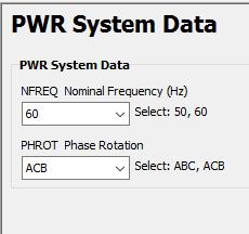
9 II. Requirements and Specifications The objective of the project is to build a radial power system with full protection. Working for Pacific Gas & Electric has enhanced my knowledge about the operation of power systems, which certified my skills to operate the protective equipment and create a functioning distribution system design [14]. The power system courses at Cal Poly helped develop the first phase of the project, which was designing the system. Table 1 below shows all the necessary specifications and requirements needed to construct the project in a safe manner. Each specification validates a major component of the design to address the ACME requirements [15]. Marketing Requirements 2,3,5,7 2,6 5,6 3,8 5 1,3 3,5 Table 1: Requirements and Specifications Engineering Justification Specifications All equipment operates on a 240 AC voltage. Protection relay timing coordinates with fault location. Device closest to the fault from the source side trips first [4]. Experiment includes four fault points, which take on LL and LLL faults. System operates radially current only flows in one direction [8]. Transformer input and output current difference is less than.5%. Transformer operates in a delta-delta configuration. System includes three protective relays, which operate the breakers. Two relays operate as an overcurrent relay and the other operates as a differential relay [14][2]. The Cal Poly lab stations operate at 120/240 V. Experiment uses a threephase 240V source. Protective device have the ability to sectionalize a portion of the line to allow some customers with power. Development of different fault duties allows for understanding how sequence parameters work hand in hand with overcurrent conditions on the system. Some distribution lines have generation from external customers, which can provide a back feed. This experiment only deals with one generating source that feeds one way. Internal magnetizing current that could force false differential tripping. The high and low side of the transformer are both delta connected to account for line loses and produce a 208V Line to Line on the secondary. These devices provide protection to the system equipment. Each device has a designated zone to protect under normal and faulted conditions. Each relay is attached to a local breaker. 3
10 3,5 1,2,3,4,7 Protective devices trip within three seconds from when the fault occurs as back up [9]. Load constructed with three-phase induction motor. Marketing Requirements 1. Low Power Circuit using 240V 2. Safety Protocols 3. Easy Measurements 4. Equipment Protection 5. Multiple Fault Points 6. No external generation 7. System operates on 60Hz 8. Radial System When a fault occurs on the line, its necessary to clear the fault before equipment gets damaged. Operating current can t go beyond 2A due line voltage drop. Motor needs 208V to operate. Additional loads would increase current input, which results in more voltage drop on the line. III. Planning The expected time frame for designing the project, gathering the material, and building was six weeks; however, it nearly doubled due to design complications. The Gantt chart below shows the expected completion of every task throughout my project. The first and only build cycle was implemented within the first 3 weeks of EE 462 build cycle 2 was not necessary. All the testing and retrieval of data was completed towards the eighth week of EE 462. Having all the relay settings completed and a functioning design schematic draw out before starting EE 462 was very beneficial. The estimated completion hours for the whole project were about 160 hours. 4

11 Figure 2: Gantt Chart 5

12 IV. Design This portion of the project includes all the design details for building the distribution system. Figure 3 and Table 2 show the inputs and outputs for the overall system and explain the basic functionality. Figure 4 and Table 3 go into an in-depth internal view of the block 0 diagram in Figure 3. The block diagrams below helped create the basic structure for this project. Table 3 explains each portion of the model to provide a purpose for the design. Module Inputs Output Functionality Table 2: Function Table for High Level Block Diagram Power Distribution Model 240 AC Voltage The line powered through this source. Faults Four locations on the system were faulted to test protection scheme. Measurements Overcurrent measurements from the downloaded relay plots. Power the system and introduce faults at the busses that are visually seen through the functional protection scheme reviewable plots generated per phase. Figure 3: High Level Block Diagram 6

13 Table 3: Function Table for Low Level Block Diagram Module Internals Details 240 AC Voltage The line powered through this source. Overcurrent relay that detects overcurrent in the line SEL 351/CB and trips the breaker to clear the fault. Protects the whole line from damages [5][10]. Resistor/Inductor Represent the transmission line impendences. Differential relay that detects the difference of current across the transformer and trips breaker if current SEL 587/CB exceeds set limit. Protects the transformer and loads from damages [6][10]. Converts the 240 V to 240 V, which allows the Transformer induction motor to operate accounting for line loss. Relay uses the overcurrent technique to protect the loading of the system by sending a signal to the Recloser/CB/CT breaker to open. The controller itself can only take an incoming signal of 1A the CT is used to lower the current of the overall system. The maximum load before the available voltage is to 3-Phase Induction Motor low due to line voltage drop. 1-3 Buses Connection points between line equipment [7]. Figure 4: Overall System Design 7
14 1. Line Protection by SEL 351 The SEL-351 relay is an overcurrent relay, which protects the transmission line. Refer to the transmission line section below for more details. This relay is programmed to trip if it picks-up a current exceeding the 51PP settings. Once the fault conditions are met, the relay will send a trip signal to command the breaker to open refer to the breakers section below for the type of breaker used and Appendix A for the relay settings. Figure 5: SEL 351x1 Front Panel Figure 6: SEL 351x1 Back Panel 8
15 Most relays require a current transformer connection to lower the current from the primary side to an allowable current on the secondary side of the relay. In this case, the currents used in this project don t exceed 2A and the relay itself has a nominal operating current of 5A allowing direct input/output connections from the system to the relay as shown in Table 4. The polarity of the trip signal doesn t matter when connecting the relay to the breaker, but the trip signal in the settings should be inverted, since the connection is made from a normally open relay to a normally closed breaker. Table 4: SEL 351 to Circuit Connections Signal Operation SEL 351 Connection Circuit Connection A Current In 201 CB 1 A Out A Current Out 202 A Line Impedance Connection (In) B Current In 203 CB 1 B Out B Current Out 204 B Line Impedance Connection (In) C Current In 205 CB 1 C Out C Current Out 206 C Line Impedance Connection (In) Trip Breaker (+) A01 CB 1 Trip (+) Trip Breaker (-) A02 CB 1 Trip (-) 9

16 Figure 7: SEL 351 and Breaker Set-Up 10


17 2. Transformer Protection by SEL 587 Figure 8: SEL 587 Front Panel Figure 9: SEL 587 Front Panel The SEL-587 relay front and back panels are shown in Figures 8 and 9 above. The SEL-587 is a differential protection relay used to provide differential current protection for the transformer. The current differential protection is used to catch any faults or anomalies between the primary and secondary windings of the transformer the input current has to be equivalent to the output current assuming it s an ideal transformer. If the relay senses an unbalanced winding current differential in any phase, it will send a trip signal to the breaker. The connections from the relay to the circuit are shown in Table 6 below. The trip signals connected between the relay and breaker are not polarity sensitive, but the signal needs to be inverted in the settings since a normally open relay is connected to a normally closed breaker. The SEL 587 relay contains internal accountability for different transformer connections Table 5 was used to accurately create settings for the design being used. The design for this project uses a delta-delta transformer as shown in Figure

18 Figure 10: Transformer Delta-Delta Connection In the initial design, a delta-wye transformer with a 2:1 ratio was being used. Alterations were made to the original design to allow for a reasonable voltage at the end of the line to meet motor specifications a 1:1 transformer ratio was used by putting two secondary windings on the panel in series to get a 240V:240V transformer. Within the settings for the relay, the value of TRCON = DACDAC and CTCON = YY. In this project, the TAPs were automatically calculated using the values provided for MVA, V LL, and CT Ratio. 12

19 Table 5: SEL 587 CT Connection Scheme Figure 11: SEL 587 and Breaker Set-Up 13
20 Table 6: SEL 587 Circuit Connections Signal Operation SEL 587 Connection Circuit Connection Primary A Current In 101 Line Impedance A (Out) Primary A Current Out 102 CB 2 A In Secondary A Current In 108 Transformer A Out Secondary A Current Out 107 CB 3 A In Primary B Current In 103 Line Impedance B (Out) Primary B Current Out 104 CB 2 B In Secondary B Current In 110 Transformer B Out Secondary B Current Out 109 CB 3 B In Primary C Current In 105 Line Impedance C (Out) Primary C Current Out 106 CB 2 C In Secondary C Current In 112 Transformer C Out Secondary C Current Out 111 CB 3 C In Trip Breaker (+) 203 CB 2 Trip (+) Trip Breaker (-) 204 CB 2 Trip (-) The connections shown in Table 6 were adjusted to conform to the project design. In differential relays, the IOP value should be close to zero, since the primary and secondary currents through the operating coil are 180 degrees out of phase. The issue arose when the secondary current measured by the relay didn t cancel out with the primary. After investigation, it was found that without using a CT, the phase shift of 180 degrees isn t applied. In order to compensate for the shift, the secondary side terminals were flipped on the relay. 14

21 3. Load Protection by Form 6 Controller The Cooper Form 6 Controller shown in Figures 12 and13 is used to act like an overcurrent relay. If the motor starts to draw high current due to a faulted condition, the controller will trip the breaker. Any fault beyond the relay should be accounted for in coordination with the other upstream devices. Figure 12: Recloser Controller Front Panel 15


22 Figure 13: Recloser Control Unit Back Panel Due to the complexity of the controller, the whole unit had to be powered up by the power supply board provided by PG&E. The power board connects to the P4 contact shown in Figure 13, which powers the controller. The ports on the controller have many different uses, but the main contacts used for the project are TB1 and P3. The pin layouts are shown in Figures 14 and 15 and Table 7. Contact P3 allows the controller to measure the current on the line. In order to control the breaker, TB1 contact was programmed as an output trip signal Figure 14: P3 Pin Numbering 16

23 Table 7: P3 Pin Descriptions Pin Number Description 1 VTC (28V Out) 2 Trip 3 Close 17 Phase A In Measurement 18 Phase B In Measurement 19 Phase C In Measurement 20 Neutral Figure 15: TB1 Pin Numbering 17

24 For measuring the currents, pins 17,18, and 19 on P3 are connected to the secondary side of the 100:5 CT in Y configuration. The primary side is connected between the output of CB3 and the motor for each phase. The controller requires a CT due the nominal operating current of 1A for the controller. The system runs a maximum of 1.6A under normal conditions to the motor, which will be dropped down by the CT factor as shown below. Due to the high voltage/current operation in utility, the controller setting doesn t allow for a 100:5 CT ratio setting the minimum is 500:1. Having different CT factors, all readings are adjusted accordingly. Actual CT Ratio: 100:5 (Lab doesn t contain a higher CT ratio) Controller Setting CT Ratio: 500:1 (Use in Industry) I Secondary = I relay = I Primary / Actual CT Ratio = 1.6A / (100:5) = 1.6A / 20 =.08A The controller measures currents that are off by a factor of 25 from the primary due to the different CT ratios. The relay reads 40A going through the line, but the current on the line is still 1.6A a factor of 25 is multiplied to the 1.6A. When preparing the settings, this factor increases the minimum to trip value by factor of 25. Figure 16: CT Connections for Form 6 Controller 18

25 In industry, pins 1,2,and 3 from Table 7 are used to control the breaker, but these pins do not work with an external breaker. The controller has built-in output ports on the TB1 contact shown in Figure 15 that are programmable to trip the breaker. Using Proview 4.0 Software, the output pins 11 & 13 (CO1 Normally Closed) are programmed to trip the breaker. The control trip/close capability is disabled since pins 1-3 are not used. This becomes an issue when the power of the system is turned on, but the controller believes there is no trip/close functionality connected so it trips the breaker through an internal trip failure alarm. The trip failure alarm can be bypassed by adding a short across the trip coil of the breaker before the system starts running. Once the power is turned on to the system, the alarms are reset from the front panel. Once the controller has reset, the short across the trip terminal of the breaker can be removed for normal operation of the Form 6 controller and breaker. Figure 17: Form 6 Unit and Breaker Set-Up 19
![4. Breakers The circuit breakers used for this project were constructed by a former Cal Poly student [17]. The unit has a switch for Normal and Fault operations.](/docs-images/77/75581256/images/26-0.jpg "In each case, three input and three output terminals are provided, which have an internal closed switch position until the breaker receives a relay signal to trip.")
26 4. Breakers The circuit breakers used for this project were constructed by a former Cal Poly student [17]. The unit has a switch for Normal and Fault operations. In each case, three input and three output terminals are provided, which have an internal closed switch position until the breaker receives a relay signal to trip. The breaker has two terminals for the close signal and two terminals for the trip signal. The inverted signal from the relay connects to the trip terminals on the circuit breaker. The unit itself operates on a DC voltage of 125V from an external source. The project focuses on line-line and three-phase faults at four different locations. A line-line fault can be created using the breaker by shorting two phases of the output terminals (black) on the fault switch section and connecting the output terminals of normal switch section to the input terminals (red) on the fault switch section, while the power is off and fault/normal switch is towards normal. Once the connections are made, turn on the power and flip the fault/normal switch to the fault position, which then introduces a line-line fault. Refer to Figure 18 below for circuit breaker connections. Figure 18: Circuit Breaker Connections [17] 20

27 5. Transmission Line The transmission line is modeled using a resistor and an inductor. As Figure 19 shows, the line is built using a 10Ω resistor and a 100mH and 40mH inductors in parallel to reduce line voltage drop. Each phase has a line impedance of 10+j10.8 Ω. Due this impedance, the line drop is close to 30V with a max current of 2A on each phase, which drops the input voltage from 240V to 190V at the terminals. Figure 19: Transmission Line (R with L L) 21
28 V. Relay Tripping & Coordination One of the main components of the project is the coordination between the SEL-351 and the Form 6 Controller. The differential relay does not come into the coordination scheme, since it has an instantaneous trip from the current differential scheme. Both overcurrent relays will trip on a time curve, which is set in the settings of the relay. Coordination is a concept, which allows for proper function of protection equipment based off the fault location. When a fault occurs on the line, the upstream devices closest to the fault should operate before any other devices operate. As impedance increases down the line, the fault currents drop due to I F =V/Z. In the project, the impedance throughout the system does not change drastically, so both relays are set at the same overcurrent trip value. Since the SEL 351 relay is closer to source compared to the Form 6 controller, the 351 uses a slower curve to operate on a fault condition U5 curve with a 1 time dial had to be used to control faults under a certain time restraint. The controller uses a different time characteristics method equations shown below for both relay methods. Time Curve Equations for SEL-351 Time Curve Equations for Form 6 Controller tp = TD*( /(M.02-1)) tr =TD*(0.323/(1-M 2 )) TD = Time Dial M = Multiples of Pickup 22

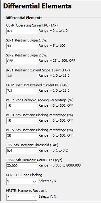
29 Figure 20: Relay Coordination Curve The graph above in Figure 20 shows the U5 curve for SEL 351 and Kyle 103 curve for the Form 6 Controller. As the curves show, when the fault current is higher, the trip time on the y-axis is less. The least amount of impedance tends to be closest to the source, which means very large currents. The detailed settings for both devices are shown in Appendix A. The setting for the maximum current on the 351 is 5A, but due to the factor of 25 offset from the CT to Form 6 Controller, the curves use 130A as the minimum to trip current for coordination purposes. The SEL-587 current differential scheme is constructed using Figure 21 below. By adjusting the O87P, U87P, and the restraint slope in the SEL-587 settings, the primary and secondary side current differential can be tuned to the design parameters. Based on Figure 21 below, the differential will trip if the set U87P value is exceeded or if the IOP does not stay within the operating region. 23

30 Figure 21: SEL 587 Trip Curve The O87P value can be adjusted if the sensitivity is too high, which prevents false tripping from high magnetization current. Full settings for SEL 587 are shown in Appendix A. VI. Programming Software Table 8: Relay Password Entrance Relay Level 1 Password Level 2 Password SEL OTTER TAIL SEL NOVA Form 6 - LS Modify -- The two main software programs used to complete the programming on the relays are SEL s Acselerator Quickset and Proview 4.0. SEL 351 and 587 relays used the quickset software, while the Form 6 Controller used Proview 4.0. The connection between the computer and the SEL relays was using an EIA 232 cable provided in lab, while the Cooper controller was connected using a R232 cable. All relays used in this project contain user manuals on how to use the software and which parameters to program for certain fault conditions. 24


31 VII. System Analysis/Data Fault 4 Location Figure 22: System Fault 4 Location - Motor Fault 3 Location Fault 2 Location Figure 23: System Fault 2 and 3 Locations CB2 and CB3 25


32 Fault 1 Location Figure 24: System Fault 1 Location End of Transmission Line Figure 25: System Single Line Circuit with Fault Locations 26
33 Figures above show the network connections for the project. The system contains four different fault locations, which are used to test the protection scheme. The first fault location is at the end of the transmission line to allow for impedance in the system. If the fault was created closer to the source, the impedance would be close to zero and the fault current would be very high. Faults 1 and 3 are both applied to visually see the SEL 351 relay trip before any other devices trip. The SEL 587 should not trip because the fault current is the same on the primary and secondary resulting in no current differential. The Form 6 Controller won t trip because the fault is upstream from the controller meaning the Form 6 Controller does not see the fault. Fault 2 is within the transformer that allows the breaker to trip instantaneously from a current differential. Since the SEL-587 is instantaneous, the SEL-351 sees the fault, but the fault is already cleared by the SEL-587 relay. The last location is fault 4, which allows the Form 6 controller to trip and tests the coordination. When the motor is faulted, all devices see the overcurrent in the system, but the Form 6 Controller is the fastest to act upon the high current. Each fault location designated in Figure 25 above has a line-line and three-phase fault applied to it. Having two different fault conditions shows how the magnitude of the fault changes with the type of fault due to positive, negative, and zero sequence parameters. In a 3-phase fault, only the positive sequence is used to calculate the fault magnitude, while a line-line fault uses both positive and negative sequence. The data for each fault location is shown below. 27

34 1. Fault 1 SEL 351 Trips for L-L and 3-Φ Faults Figure 26: L-L Fault Phase Currents Figure 27: L-L Phasor Diagram 28

35 Figure 28: 3-Φ Fault Phase Currents Figure 29: 3-Φ Phasor Diagram 29
36 The four figures above show the results of Fault 1 with line-line and three-phase fault applied. In both cases, the SEL 351 tells the breaker to open after 5 cycles of an overcurrent. Phases A and B are connected together to introduce the line-line fault and the data shows that both those phases have currents over 8A, while phase C only has 4A. For the three-phase fault, all phase are connected together and the result show equal amount of overcurrent on all three phases. The higher current amplitude in the three-phase exists because a three-phase fault only uses positive sequence when determining fault currents. The line-line fault uses both positive and negative, which results in a higher impedance. 2. Fault 2 SEL 587 Trips for L-L and 3-Φ Faults Figure 30: L-L Fault Phase Currents Figure 30 above shows the fault currents on the primary and secondary side of the transformer when a line-line fault is introduced. It s hard to distinguish the magnitude of each phase, so Figure 32 below shows the current differential on phase B. Since the fault is line-line, only phase A and B alarm for the differential difference. 30
37 Figure 31: L-L Fault IOP Plot Figure 32: L-L Fault Phase B Current Differential Figure 32 above shows primary and secondary currents for phase B. Curves are taken directly from Figure 30. Since the fault is within the transformer, the primary side sees excess current. The secondary current is fluctuating to zero because the motor is back feeding into the system. Within the second cycle, the secondary current has reached close to zero as expected. 31
38 The IOP curves in Figure 31 show that phases A and B have a current differential. Under normal operation, the primary and secondary currents are equal, which results in an IOP value close to zero. In the faulted case above, the current magnitude on the primary side is high and the current magnitude on the secondary is close to zero. The current differential between the two sides results in a high IOP value, since the currents running through the operating coil do not cancel. The maximum IOP value allowed before the breaker trips is set by the U87P parameter, which is set to 7.3A in the SEL-587 settings. As shown in Figure 31, the U87P value is exceeded for both phases. Figure 33: 3-Φ IOP Plot Figure 34: 3-Φ Fault Phase Currents (Primary/Secondary) 32

39 The same situation for the three-phase fault within the transformer follows. Each phase magnitude is much greater on the primary compared to the secondary, which tells the SEL-587 to trip the breaker instantaneously after five cycles. Compared to the previous IOP curve for the line-line fault, the IOP values in Figure 33 all exceed 7.3A, which initiates the trip. 3. Fault 3 SEL 351 Trips for L-L and 3-Φ Faults Figure 35: L-L Fault Phase Currents Figure 36: L-L Phasor Diagram 33

40 Figure 37: 3-Φ Fault Phase Currents Figure 38: 3-Φ Phasor Diagram Fault 3 uses the SEL-351 relay to trip on an overcurrent. Testing showed that the SEL-351 is the first to trip, since it s the first upstream device providing overcurrent protection. The SEL-587 does see the excess current, but doesn t trip for an overcurrent. 34
41 4. Fault 4 Form 6 Controller Trips for L-L and 3-Φ Faults Once the system receives power, the controller starts to pick-up current values. As shown in Figures 39 and 41, when a line-line or three-phase fault was applied, the breaker tripped after two cycles. Since the Form 6 Controller is at the end of the line, it acts as an instantaneous trip when a fault condition is present. The coordination between the Form 6 Controller and SEL-351 is important in this fault location because both relays see the fault. The coordination section above explains which curves were used for both relays to get the correct tripping. The first few trials, the SEL-351 tripped before the Form 6. Once the time-current curves were adjusted, the system worked as designed. Figure 39: 3-Φ Fault Phase Currents Figure 40: 3-Φ Fault Logic Levels 35
42 Figure 41: L-L Fault Phase Currents Figure 42: L-L Fault Logic Levels 36
43 VIII. Conclusion The overall project turned out to be a success. The initial design went through many adjustment phases to finally result a functional power system that could be tested in the lab. Each zone of the radial system was protected by a relay. The transmission line was protected by SEL-351 relay, the transformer was protected by SEL-587 relay, and the Form 6 Controller protected the motor. Each relay performed its assigned responsibility under line-line and three-phase fault conditions. A major component of the project was to come up with a protection scheme that protected the entire system and allowed for proper coordination. In all four different fault locations, the closest upstream device tripped the local breaker when a fault was present. One downfall of this project was not having the correct sized current transformer for the Form 6 Controller; this introduced some complications in measuring and tripping the breaker. Beside some other minor adjustments, the project was a great way to get hands on experience with industry standard equipment. The progression through electrical engineering courses allows for students to properly understand power system engineering concepts and apply them in industry. Using the knowledge obtained from these courses, a functioning small power distribution system design with a proper protection scheme was developed. In industry, both electromechanical and microprocessor relays are used for system protection, but the concept remains the same. After reading the user manuals, the settings were made based on the system design and programmed into the relay. The system construction and testing process provided good experience in power system protection. Another benefit of this project was familiarization with different relays used in industry. 37
44 IX. References 1. Cooper Power Systems , Reclosers: Form 6 Controller [Online], Available [Jan. 30, 2016]: ntrols/s pdf 2. J. D. Glover, Power System Control, in Power System Analysis and Design, 5th ed. Cengage Learning, 2012, Ch. 12, pp K. Nishijima, Power Distribution Line Protection System, U.S. Patent US , March 15, M. A. Anthony, Electric Power System Protection and Coordination: A Design Handbook for Overcurrent Protection, McGraw Hill, Schweitzer Engineering Laboratories. ( ), SEL 351 Distribution and Transmission Relay [Online], Available [January 30, 2016]: 6. Schweitzer Engineering Laboratories. ( ), SEL 587 Current Differential Relay [Online], Available [January 30, 2016]: 7. S. Hanna, Power Protection Analysis for a Ten Bus System, Senior Project, Dept. Electrical Eng., Cal Poly, San Luis Obispo, California, T. Gonen, Distribution System Planning Models, in Electric Power Distribution Engineering, 3 rd ed. CRC Press, 2014, pp Urdaneta, A.J.; Nadira, R.; Perez Jimenez, L.G. "Optimal coordination of directional overcurrent relays in interconnected power systems", Power Delivery, IEEE Transactions on, On page(s): Volume: 3, Issue: 3, Jul Wikipedia, "Circuit breaker", [Online]. Available: [Accessed: 30- Jan- 2016]. 11. EPA, "The Electricity System Energy and the Environment US EPA", [Online]. Available: [Accessed: 14- Feb- 2016]. 12. P. Giovinazzo, "Electrical Safety: The Fatal Current", Ohio State, [Online]. Available: [Accessed: 20- Feb- 2016]. 13. Eia.gov, "Electric Power Annual U.S. Energy Information Administration", [Online]. Available: [Accessed: 26- Feb- 2016]. 14. J. Tuccillo, "Power Distribution with PG&E Interview, Pacific Gas & Electric, R. Ford and C. Coulston, Design for Electrical and Computer Engineers, McGraw-Hill, IEEE Board of Directors, IEEE Code of Ethics, 2006, Cited 02/26/ O. Corulli, Motor Protection Lab Experiment Using SEL-710, Dept. Elect. Eng., California Polytechnic State Univ., San Luis Obispo, Senior Project Report, Jun


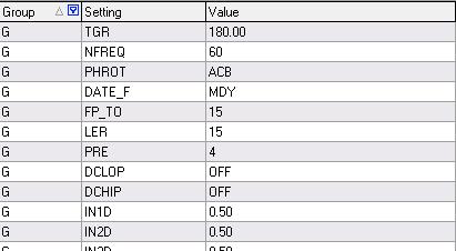
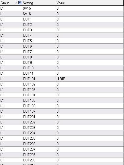
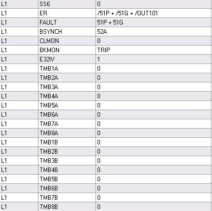
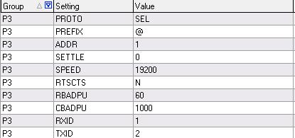
45 Appendix A i. SEL 351 Settings 39

46 40
47 41

48 ii. SEL 587 Settings 42
49 43
50 44
51 45


52 iii. Copper Form 6 Controller Settings NOTE: Ground tripping was not used due to delta system. 46
DIFFERENTIAL TRANSFORMER PROTECTION USING THE SEL 387 AND SEL 587 MICROPROCESSOR RELAYS
 DIFFERENTIAL TRANSFORMER PROTECTION USING THE SEL 387 AND SEL 587 MICROPROCESSOR RELAYS Ryan Chun Senior Project Electrical Engineering Department California Polytechnic State University San Luis Obispo
Microgrid Protection Student Laboratory
 Microgrid Protection Student Laboratory Ian Hellman-Wylie and Joey Navarro Senior Project California Polytechnic State University San Luis Obispo 2017 Abstract To better prepare students for careers in
Verifying Transformer Differential Compensation Settings
 Verifying Transformer Differential Compensation Settings Edsel Atienza and Marion Cooper Schweitzer Engineering Laboratories, Inc. Presented at the 6th International Conference on Large Power Transformers
Transformer Protection
 Transformer Protection Transformer Protection Outline Fuses Protection Example Overcurrent Protection Differential Relaying Current Matching Phase Shift Compensation Tap Changing Under Load Magnetizing
Transformer Differential Protection Lab
 Montana Tech Library Digital Commons @ Montana Tech Proceedings of the Annual Montana Tech Electrical and General Engineering Symposium Student Scholarship 2016 Transformer Differential Protection Lab
Overcurrent Elements
 Exercise Objectives Hands-On Relay Testing Session Overcurrent Elements After completing this exercise, you should be able to do the following: Identify overcurrent element settings. Determine effective
Time-current Coordination
 269 5.2.3.1 Time-current Coordination Time that is controlled by current magnitude permits discriminating faults at one location from another. There are three variables available to discriminate faults,
PROTECTION of electricity distribution networks
 PROTECTION of electricity distribution networks Juan M. Gers and Edward J. Holmes The Institution of Electrical Engineers Contents Preface and acknowledgments x 1 Introduction 1 1.1 Basic principles of
EE Lecture 14 Wed Feb 8, 2017
 EE 5223 - Lecture 14 Wed Feb 8, 2017 Ongoing List of Topics: URL: http://www.ece.mtu.edu/faculty/bamork/ee5223/index.htm Labs - EE5224 Lab 3 - begins on Tues Feb 14th Term Project - details posted. Limit
Power systems Protection course
 Al-Balqa Applied University Power systems Protection course Department of Electrical Energy Engineering 1 Part 5 Relays 2 3 Relay Is a device which receive a signal from the power system thought CT and
NERC Protection Coordination Webinar Series June 9, Phil Tatro Jon Gardell
 Power Plant and Transmission System Protection Coordination GSU Phase Overcurrent (51T), GSU Ground Overcurrent (51TG), and Breaker Failure (50BF) Protection NERC Protection Coordination Webinar Series
Generator Protection GENERATOR CONTROL AND PROTECTION
 Generator Protection Generator Protection Introduction Device Numbers Symmetrical Components Fault Current Behavior Generator Grounding Stator Phase Fault (87G) Field Ground Fault (64F) Stator Ground Fault
www. ElectricalPartManuals. com Transformer Differential Relay MD32T Transformer Differential Relay
 Transformer Differential Relay The MD3T Transformer Differential Relay is a member of Cooper Power Systems Edison line of microprocessor based protective relays. The MD3T relay offers the following functions:
TECHNICAL BULLETIN 004a Ferroresonance
 May 29, 2002 TECHNICAL BULLETIN 004a Ferroresonance Abstract - This paper describes the phenomenon of ferroresonance, the conditions under which it may appear in electric power systems, and some techniques
Numbering System for Protective Devices, Control and Indication Devices for Power Systems
 Appendix C Numbering System for Protective Devices, Control and Indication Devices for Power Systems C.1 APPLICATION OF PROTECTIVE RELAYS, CONTROL AND ALARM DEVICES FOR POWER SYSTEM CIRCUITS The requirements
POWER SYSTEM ANALYSIS TADP 641 SETTING OF OVERCURRENT RELAYS
 POWER SYSTEM ANALYSIS TADP 641 SETTING OF OVERCURRENT RELAYS Juan Manuel Gers, PhD Protection coordination principles Relay coordination is the process of selecting settings that will assure that the relays
AC System Monitoring Device
 AC System Monitoring Device Andrew Jarrett Project Adviser: Professor Steven D.Gutschlag Department of Electrical and Computer Engineering May 11, 2016 ABSTRACT This document covers the design of a device
Protection of a 138/34.5 kv transformer using SEL relay
 Scholars' Mine Masters Theses Student Theses and Dissertations Fall 2016 Protection of a 138/34.5 kv transformer using SEL 387-6 relay Aamani Lakkaraju Follow this and additional works at: http://scholarsmine.mst.edu/masters_theses
Hands On Relay School Open Lecture Transformer Differential Protection Scott Cooper
 Hands On Relay School Open Lecture Transformer Differential Protection Scott Cooper Transformer Differential Protection ntroduction: Transformer differential protection schemes are ubiquitous to almost
Bus Protection Fundamentals
 Bus Protection Fundamentals Terrence Smith GE Grid Solutions 2017 Texas A&M Protective Relay Conference Bus Protection Requirements High bus fault currents due to large number of circuits connected: CT
Distance Relay Response to Transformer Energization: Problems and Solutions
 1 Distance Relay Response to Transformer Energization: Problems and Solutions Joe Mooney, P.E. and Satish Samineni, Schweitzer Engineering Laboratories Abstract Modern distance relays use various filtering
Substation Testing and Commissioning: Power Transformer Through Fault Test
 1 Substation Testing and Commissioning: Power Transformer Through Fault Test M. Talebi, Member, IEEE, Power Grid Engineering Y. Unludag Electric Power System Abstract This paper reviews the advantage of
Arizona Public Service Company and the Transmission Partnership for National Electric Power Company of Jordan
 Arizona Public Service Company and the Transmission Partnership for National Electric Power Company of Jordan Mark Hackney October 5-8, 2009 Amman, Jordan Energy Control Center Layout 2 Energy Control
ISSN: Page 298
 Sizing Current Transformers Rating To Enhance Digital Relay Operations Using Advanced Saturation Voltage Model *J.O. Aibangbee 1 and S.O. Onohaebi 2 *Department of Electrical &Computer Engineering, Bells
Protective Relaying for DER
 Protective Relaying for DER Rogerio Scharlach Schweitzer Engineering Laboratories, Inc. Basking Ridge, NJ Overview IEEE 1547 general requirements to be met at point of common coupling (PCC) Distributed
Protective Relays Digitrip 3000
 New Information Technical Data Effective: May 1999 Page 1 Applications Provides reliable 3-phase and ground overcurrent protection for all voltage levels. Primary feeder circuit protection Primary transformer
Electrical Protection System Design and Operation
 ELEC9713 Industrial and Commercial Power Systems Electrical Protection System Design and Operation 1. Function of Electrical Protection Systems The three primary aims of overcurrent electrical protection
Busbars and lines are important elements
 CHAPTER CHAPTER 23 Protection of Busbars and Lines 23.1 Busbar Protection 23.2 Protection of Lines 23.3 Time-Graded Overcurrent Protection 23.4 Differential Pilot-Wire Protection 23.5 Distance Protection
Hands On Relay School Open Lecture Transformer Differential Protection Scott Cooper
 Hands On Relay School Open Lecture Transformer Differential Protection Scott Cooper Transformer Differential Protection ntroduction: Transformer differential protection schemes are ubiquitous to almost
System Protection and Control Subcommittee
 Power Plant and Transmission System Protection Coordination Reverse Power (32), Negative Sequence Current (46), Inadvertent Energizing (50/27), Stator Ground Fault (59GN/27TH), Generator Differential (87G),
Relay-assisted commissioning
 Relay-assisted commissioning by Casper Labuschagne and Normann Fischer, Schweitzer Engineering Laboratories (SEL) Power transformer differential relays were among the first protection relays to use digital
Protection Introduction
 1.0 Introduction Protection 2 There are five basic classes of protective relays: Magnitude relays Directional relays Ratio (impedance) relays Differential relays Pilot relays We will study each of these.
Event Analysis Tutorial
 1 Event Analysis Tutorial Part 1: Problem Statements David Costello, Schweitzer Engineering Laboratories, Inc. Abstract Event reports have been an invaluable feature in microprocessor-based relays since
EE Lecture 15 (recorded Feb 9, 2011) Fri Feb 15, 2013
 Fri Feb 15, 2013") EE 5223 - Lecture 15 (recorded Feb 9, 2011) Fri Feb 15, 2013 Ongoing List of Topics: URL: http://www.ece.mtu.edu/faculty/bamork/ee5223/index.htm Term Project - structuring, details Exercises posted Today:
EE 5223 - Lecture 15 (recorded Feb 9, 2011) Fri Feb 15, 2013 Ongoing List of Topics: URL: http://www.ece.mtu.edu/faculty/bamork/ee5223/index.htm Term Project - structuring, details Exercises posted Today:
TABLE OF CONTENT
 Page : 1 of 34 Project Engineering Standard www.klmtechgroup.com KLM Technology #03-12 Block Aronia, Jalan Sri Perkasa 2 Taman Tampoi Utama 81200 Johor Bahru Malaysia TABLE OF CONTENT SCOPE 3 REFERENCES
Transmission Protection Overview
 Transmission Protection Overview 2017 Hands-On Relay School Daniel Henriod Schweitzer Engineering Laboratories Pullman, WA Transmission Line Protection Objective General knowledge and familiarity with
Forward to the Basics: Selected Topics in Distribution Protection
 Forward to the Basics: Selected Topics in Distribution Protection Lee Underwood and David Costello Schweitzer Engineering Laboratories, Inc. Presented at the IEEE Rural Electric Power Conference Orlando,
A NEW DIRECTIONAL OVER CURRENT RELAYING SCHEME FOR DISTRIBUTION FEEDERS IN THE PRESENCE OF DG
 A NEW DIRECTIONAL OVER CURRENT RELAYING SCHEME FOR DISTRIBUTION FEEDERS IN THE PRESENCE OF DG CHAPTER 3 3.1 INTRODUCTION In plain radial feeders, the non-directional relays are used as they operate when
Relaying 101. by: Tom Ernst GE Grid Solutions
 Relaying 101 by: Tom Ernst GE Grid Solutions Thomas.ernst@ge.com Relaying 101 The abridged edition Too Much to Cover Power system theory review Phasor domain representation of sinusoidal waveforms 1-phase
Reducing the Effects of Short Circuit Faults on Sensitive Loads in Distribution Systems
 Reducing the Effects of Short Circuit Faults on Sensitive Loads in Distribution Systems Alexander Apostolov AREVA T&D Automation I. INTRODUCTION The electric utilities industry is going through significant
Optimum Coordination of Overcurrent Relays: GA Approach
 Optimum Coordination of Overcurrent Relays: GA Approach 1 Aesha K. Joshi, 2 Mr. Vishal Thakkar 1 M.Tech Student, 2 Asst.Proff. Electrical Department,Kalol Institute of Technology and Research Institute,
POWER SYSTEM ANALYSIS TADP 641 SETTING EXAMPLE FOR OVERCURRENT RELAYS
 POWER SYSTEM ANALYSIS TADP 641 SETTING EXAMPLE FOR OVERCURRENT RELAYS Juan Manuel Gers, PhD Example - Single Line Example 1 - Data Calculate the following: 1. The three phase short circuit levels on busbars
Visualization and Animation of Protective Relay Operation
 Visualization and Animation of Protective Relay Operation A. P. Sakis Meliopoulos School of Electrical and Computer Engineering Georgia Institute of Technology Atlanta, Georgia 30332 George J. Cokkinides
A Tutorial on the Application and Setting of Collector Feeder Overcurrent Relays at Wind Electric Plants
 A Tutorial on the Application and Setting of Collector Feeder Overcurrent Relays at Wind Electric Plants Martin Best and Stephanie Mercer, UC Synergetic, LLC Abstract Wind generating plants employ several
ENOSERV 2014 Relay & Protection Training Conference Course Descriptions
 ENOSERV 2014 Relay & Protection Training Conference Course Descriptions Day 1 Generation Protection/Motor Bus Transfer Generator Protection: 4 hours This session highlights MV generator protection and
Protection Basics Presented by John S. Levine, P.E. Levine Lectronics and Lectric, Inc GE Consumer & Industrial Multilin
 Protection Basics Presented by John S. Levine, P.E. Levine Lectronics and Lectric, Inc. 770 565-1556 John@L-3.com 1 Protection Fundamentals By John Levine 2 Introductions Tools Outline Enervista Launchpad
UPGRADING SUBSTATION RELAYS TO DIGITAL RECLOSERS AND THEIR COORDINATION WITH SECTIONALIZERS
 UPGRADING SUBSTATION RELAYS TO DIGITAL RECLOSERS AND THEIR COORDINATION WITH SECTIONALIZERS 1 B. RAMESH, 2 K. P. VITTAL Student Member, IEEE, EEE Department, National Institute of Technology Karnataka,
ECE 421 Introduction to Power Systems. Lab 02 Power System Feeding Different Loads
 Fall 201 Lab 02 ECE 421 Introduction to Power Systems Lab 02 Power System Feeding Different Loads 1. Objective Analyzing system behavior feeding different types of loads and impacts of load variations;
BE1-67N GROUND DIRECTIONAL OVERCURRENT RELAY FEATURES ADDITIONAL INFORMATION. FUNCTIONS AND FEATURES Pages 2-4. APPLICATIONS Page 2
 BE1-67N GROUND DIRECTIONAL OVERCURRENT RELAY The BE1-67N Ground Directional Overcurrent Relay provides ground fault protection for transmission and distribution lines by sensing the direction and magnitude
Micro grid Protection Using Digital Relays Mr.Karthik.P 1, Mrs.Belwin J. Brearley 2
 Micro grid Protection Using Digital Relays Mr.Karthik.P 1, Mrs.Belwin J. Brearley 2 PG Student [PED], Dept. of EEE, B.S.AbdurRahman University, Chennai, Tamilnadu, India 1 Assistant professor, Dept. of
This document covers common questions concerning the design of an effectively grounded system.
 This document covers common questions concerning the design of an effectively grounded system. To prevent against temporary overvoltage conditions when a line-to-ground fault occurs on the power grid.
Transmission System Phase Backup Protection
 Reliability Guideline Transmission System Phase Backup Protection NERC System Protection and Control Subcommittee Draft for Planning Committee Approval June 2011 Table of Contents 1. Introduction and Need
Overcurrent and Overload Protection of AC Machines and Power Transformers
 Exercise 2 Overcurrent and Overload Protection of AC Machines and Power Transformers EXERCISE OBJECTIVE When you have completed this exercise, you will understand the relationship between the power rating
Transmission Line Protection Objective. General knowledge and familiarity with transmission protection schemes
 Transmission Line Protection Objective General knowledge and familiarity with transmission protection schemes Transmission Line Protection Topics Primary/backup protection Coordination Communication-based
PROTECTION, AUTOMATION, AND FREQUENCY STABILITY ANALYSIS OF A LABORATORY MICROGRID SYSTEM. A Thesis. presented to
 PROTECTION, AUTOMATION, AND FREQUENCY STABILITY ANALYSIS OF A LABORATORY MICROGRID SYSTEM A Thesis presented to the Faculty of California Polytechnic State University, San Luis Obispo In Partial Fulfillment
EEL 3086 SWITCHGEAR AND PROTECTION EXPERIMENT 2 DIFFERENTIAL PROTECTION OF A THREE-PHASE TRANSFORMER
 EEL 3086 SWITCHGEAR AND PROTECTION EXPERIMENT 2 DIFFERENTIAL PROTECTION OF A THREE-PHASE TRANSFORMER Objective To analyse the differential protection scheme as applied to a three-phase power transformer
IDAHO PURPA GENERATOR INTERCONNECTION REQUEST (Application Form)
") IDAHO PURPA GENERATOR INTERCONNECTION REQUEST (Application Form) Transmission Provider: IDAHO POWER COMPANY Designated Contact Person: Jeremiah Creason Address: 1221 W. Idaho Street, Boise ID 83702 Telephone
IDAHO PURPA GENERATOR INTERCONNECTION REQUEST (Application Form) Transmission Provider: IDAHO POWER COMPANY Designated Contact Person: Jeremiah Creason Address: 1221 W. Idaho Street, Boise ID 83702 Telephone
Back to the Basics Current Transformer (CT) Testing
 Testing") Back to the Basics Current Transformer (CT) Testing As test equipment becomes more sophisticated with better features and accuracy, we risk turning our field personnel into test set operators instead of
Back to the Basics Current Transformer (CT) Testing As test equipment becomes more sophisticated with better features and accuracy, we risk turning our field personnel into test set operators instead of
1 INTRODUCTION 1.1 PRODUCT DESCRIPTION
 GEK-00682D INTRODUCTION INTRODUCTION. PRODUCT DESCRIPTION The MDP Digital Time Overcurrent Relay is a digital, microprocessor based, nondirectional overcurrent relay that protects against phase-to-phase
Catastrophic Relay Misoperations and Successful Relay Operation
 Catastrophic Relay Misoperations and Successful Relay Operation Steve Turner (Beckwith Electric Co., Inc.) Introduction This paper provides detailed technical analysis of several catastrophic relay misoperations
Power System Protection Part VII Dr.Prof.Mohammed Tawfeeq Al-Zuhairi. Differential Protection (Unit protection)
") Differential Protection (Unit protection) Differential Protection Differential protection is the best technique in protection. In this type of protection the electrical quantities entering and leaving
Differential Protection (Unit protection) Differential Protection Differential protection is the best technique in protection. In this type of protection the electrical quantities entering and leaving
Transformer Trainer. Electrical Power Systems PSL20. Learning Outcomes. Key Features. Key Specifications
 Electrical Power Systems PSL2 Investigates the principles and operating characteristics of single-phase and three-phase power and distribution transformers Key Features Educational transformers with fully
O V E R V I E W O F T H E
 A CABLE Technicians TESTING Approach to Generator STANDARDS: Protection O V E R V I E W O F T H E 1 Moderator n Ron Spataro AVO Training Institute Marketing Manager 2 Q&A n Send us your questions and comments
ATP modeling of internal transformer faults for relay performance testing
 Michigan Technological University Digital Commons @ Michigan Tech Dissertations, Master's Theses and Master's Reports - Open Dissertations, Master's Theses and Master's Reports 2011 ATP modeling of internal
PRC Generator Relay Loadability. Guidelines and Technical Basis Draft 5: (August 2, 2013) Page 1 of 76
 Page 1 of 76") PRC-025-1 Introduction The document, Power Plant and Transmission System Protection Coordination, published by the NERC System Protection and Control Subcommittee (SPCS) provides extensive general discussion
PRC-025-1 Introduction The document, Power Plant and Transmission System Protection Coordination, published by the NERC System Protection and Control Subcommittee (SPCS) provides extensive general discussion
U I. Time Overcurrent Relays. Basic equation. More or less approximates thermal fuse. » Allow coordination with fuses 9/24/2018 ECE525.
 Time Overcurrent Relays More or less approximates thermal fuse» Allow coordination with fuses Direction of Current nduced Torque Restraining Spring Reset Position Time Dial Setting Disk Basic equation
Overcurrent Protective Relays
 Power System Protection Overcurrent Protective Relays Dr.Professor Mohammed Tawfeeq Lazim Alzuhairi 99 Power system protection Dr.Mohammed Tawfeeq Overcurrent Protective Relays Overcurrent relays Overcurrent
Improving Transformer Protection
 Omaha, NB October 12, 2017 Improving Transformer Protection Wayne Hartmann VP, Customer Excellence Senior Member, IEEE Wayne Hartmann Senior VP, Customer Excellence Speaker Bio whartmann@beckwithelectric.com
ARC FLASH PPE GUIDELINES FOR INDUSTRIAL POWER SYSTEMS
 The Electrical Power Engineers Qual-Tech Engineers, Inc. 201 Johnson Road Building #1 Suite 203 Houston, PA 15342-1300 Phone 724-873-9275 Fax 724-873-8910 www.qualtecheng.com ARC FLASH PPE GUIDELINES FOR
PRC Generator Relay Loadability. Guidelines and Technical Basis Draft 4: (June 10, 2013) Page 1 of 75
 Page 1 of 75") PRC-025-1 Introduction The document, Power Plant and Transmission System Protection Coordination, published by the NERC System Protection and Control Subcommittee (SPCS) provides extensive general discussion
PRC-025-1 Introduction The document, Power Plant and Transmission System Protection Coordination, published by the NERC System Protection and Control Subcommittee (SPCS) provides extensive general discussion
SEL-311C TRANSMISSION PROTECTION SYSTEM
 SEL-3C TRANSMISSION PROTECTION SYSTEM ADVANCED TRANSMISSION LINE PROTECTION, AUTOMATION, AND CONTROL Bus ANSI NUMBERS/ACRONYMS AND FUNCTIONS 52 3 3 2 P G 8 O U 27 68 50BF 67 P G Q 50 P G Q 59 P G Q 5 P
DESIGN OF A DIFFERENTIAL PROTECTION SCHEME FOR A 345 KV TRANSMISSION LINE USING SEL 311L RELAYS TARANGINI KAROOR SUBRAHMANYAM
 DESIGN OF A DIFFERENTIAL PROTECTION SCHEME FOR A 345 KV TRANSMISSION LINE USING SEL 311L RELAYS by TARANGINI KAROOR SUBRAHMANYAM B.E., OSMANIA UNIVERSITY, 2011 A REPORT submitted in partial fulfillment
NERC Protection Coordination Webinar Series June 16, Phil Tatro Jon Gardell
 Power Plant and Transmission System Protection Coordination Phase Distance (21) and Voltage-Controlled or Voltage-Restrained Overcurrent Protection (51V) NERC Protection Coordination Webinar Series June
Poly Canyon Cogeneration System
 Poly Canyon Cogeneration System By Jaideep Gill Senior Project Electrical Engineering Department California Polytechnic State University San Luis Obispo 2011 ii Table of Contents Section Acknowledgements
Distance Element Performance Under Conditions of CT Saturation
 Distance Element Performance Under Conditions of CT Saturation Joe Mooney Schweitzer Engineering Laboratories, Inc. Published in the proceedings of the th Annual Georgia Tech Fault and Disturbance Analysis
COPYRIGHTED MATERIAL. Index
 Index Note: Bold italic type refers to entries in the Table of Contents, refers to a Standard Title and Reference number and # refers to a specific standard within the buff book 91, 40, 48* 100, 8, 22*,
Power System Protection. Dr. Lionel R. Orama Exclusa, PE Week 3
 Power System Protection Dr. Lionel R. Orama Exclusa, PE Week 3 Operating Principles: Electromagnetic Attraction Relays Readings-Mason Chapters & 3 Operating quantities Electromagnetic attraction Response
Appendix S: PROTECTION ALTERNATIVES FOR VARIOUS GENERATOR CONFIGURATIONS
 Appendix S: PROTECTION ALTERNATIVES FOR VARIOUS GENERATOR CONFIGURATIONS S1. Standard Interconnection Methods with Typical Circuit Configuration for Single or Multiple Units Note: The protection requirements
UProtection Requirements. Ufor a Large scale Wind Park. Shyam Musunuri Siemens Energy
 UProtection Requirements Ufor a Large scale Wind Park Shyam Musunuri Siemens Energy Abstract: In the past wind power plants typically had a small power rating when compared to the strength of the connected
Current Transformer Requirements for VA TECH Reyrolle ACP Relays. PREPARED BY:- A Allen... APPROVED :- B Watson...
 TECHNICAL REPORT APPLICATION GUIDE TITLE: Current Transformer Requirements for VA TECH Reyrolle ACP Relays PREPARED BY:- A Allen... APPROVED :- B Watson... REPORT NO:- 990/TIR/005/02 DATE :- 24 Jan 2000
Sequence Networks p. 26 Sequence Network Connections and Voltages p. 27 Network Connections for Fault and General Unbalances p. 28 Sequence Network
 Preface p. iii Introduction and General Philosophies p. 1 Introduction p. 1 Classification of Relays p. 1 Analog/Digital/Numerical p. 2 Protective Relaying Systems and Their Design p. 2 Design Criteria
NERC Protection Coordination Webinar Series July 15, Jon Gardell
 Power Plant and Transmission System Protection Coordination Reverse Power (32), Negative Sequence Current (46), Inadvertent Energizing (50/27), Stator Ground Fault (59GN/27TH), Generator Differential (87G),
Negative-Sequence Based Scheme For Fault Protection in Twin Power Transformer
 Negative-Sequence Based Scheme For Fault Protection in Twin Power Transformer Ms. Kanchan S.Patil PG, Student kanchanpatil2893@gmail.com Prof.Ajit P. Chaudhari Associate Professor ajitpc73@rediffmail.com
www. ElectricalPartManuals. com Type CGR Ratio Ground Relay Descriptive Bulletin Page 1
 November, 1981 New nformation Mailed to: E,D,C/211, 219/DB Westinghouse Electric Corporation Relay-nstrument Division Coral Springs, FL 65 Page 1 Type CGR Ratio Ground Relay "" Page 2 Application Three
Protection Challenges for Transmission Lines with Long Taps
 Protection Challenges for Transmission Lines with Long Taps Jenny Patten, Majida Malki, Quanta Technology, Matt Jones, American Transmission Co. Abstract Tapped transmission lines are quite common as they
Using a Multiple Analog Input Distance Relay as a DFR
 Using a Multiple Analog Input Distance Relay as a DFR Dennis Denison Senior Transmission Specialist Entergy Rich Hunt, M.S., P.E. Senior Field Application Engineer NxtPhase T&D Corporation Presented at
Capstone Turbine Corporation Nordhoff Street Chatsworth CA USA Phone: (818) Fax: (818) Web:
 Fax: (818) Web:") Phone: (818) 734-5300 Fax: (818) 734-5320 Web: www.capstoneturbine.com Technical Reference Capstone MicroTurbine Electrical Installation 410009 Rev F (October 2013) Page 1 of 31 Capstone Turbine Corporation
Phone: (818) 734-5300 Fax: (818) 734-5320 Web: www.capstoneturbine.com Technical Reference Capstone MicroTurbine Electrical Installation 410009 Rev F (October 2013) Page 1 of 31 Capstone Turbine Corporation
www. ElectricalPartManuals. com Generator Differential Relay MD32G Rotating Machine Differential Relay
 Generator Differential Relay The MD3G Rotating Machine Differential Relay is a member of Cooper Power Systems Edison line of microprocessor based protective relays. The MD3G relay offers the following
Pinhook 500kV Transformer Neutral CT Saturation
 Russell W. Patterson Tennessee Valley Authority Presented to the 9th Annual Fault and Disturbance Analysis Conference May 1-2, 26 Abstract This paper discusses the saturation of a 5kV neutral CT upon energization
Shortcomings of the Low impedance Restricted Earth Fault function as applied to an Auto Transformer. Anura Perera, Paul Keller
 Shortcomings of the Low impedance Restricted Earth Fault function as applied to an Auto Transformer Anura Perera, Paul Keller System Operator - Eskom Transmission Introduction During the design phase of
Three Phase Transformers
 EE/CME 392 Laboratory 6-1 Three Phase Transformers Safety The voltages used in this experiment are lethal. Assemble or modify a circuit only with the breakers off. Do not apply power until the wiring has
Unit Protection Differential Relays
 Unit Protection PROF. SHAHRAM MONTASER KOUHSARI Current, pu Current, pu Protection Relays - BASICS Note on CT polarity dots Through-current: must not operate Internal fault: must operate The CT currents
PD300. Transformer, generator and motor protection Data sheet
 PD300 Transformer, generator and motor protection Data sheet DSE_PD300_eng_AO No part of this publication may be reproduced by whatever means without the prior written permission of Ingeteam T&D. One of
DESIGN ANALYSIS AND REALIZATION OF MICROCONTROLLER BASED OVER CURRENT RELAY WITH IDMT CHARACTERISTICS: A PROTEUS SIMULATION
 DESIGN ANALYSIS AND REALIZATION OF MICROCONTROLLER BASED OVER CURRENT RELAY WITH IDMT CHARACTERISTICS: A PROTEUS SIMULATION HARSH DHIMAN Department of Electrical Engineering, The M. S. University, Vadodara,
Adaptive Relaying of Radial Distribution system with Distributed Generation
 Adaptive Relaying of Radial Distribution system with Distributed Generation K.Vijetha M,Tech (Power Systems Engineering) National Institute of Technology-Warangal Warangal, INDIA. Email: vijetha258@gmail.com
NORTH CAROLINA INTERCONNECTION REQUEST. Utility: Designated Contact Person: Address: Telephone Number: Address:
 NORTH CAROLINA INTERCONNECTION REQUEST Utility: Designated Contact Person: Address: Telephone Number: Fax: E-Mail Address: An is considered complete when it provides all applicable and correct information
Impact of transient saturation of Current Transformer during cyclic operations Analysis and Diagnosis
 1 Impact of transient saturation of Current Transformer during cyclic operations Analysis and Diagnosis BK Pandey, DGM(OS-Elect) Venkateswara Rao Bitra, Manager (EMD Simhadri) 1.0 Introduction: Current
Setting Generic Distance Relay UTP-100#WPSC1. in the. Computer-Aided Protection Engineering System (CAPE)
") Setting Generic Distance Relay UTP-100#WPSC1 in the Computer-Aided Protection Engineering System (CAPE) Prepared for CAPE Users' Group August 6, 1998 Revised August 24, 1998 Electrocon International, Inc.
Setting Generic Distance Relay UTP-100#WPSC1 in the Computer-Aided Protection Engineering System (CAPE) Prepared for CAPE Users' Group August 6, 1998 Revised August 24, 1998 Electrocon International, Inc.
POWER SYSTEM PRINCIPLES APPLIED IN PROTECTION PRACTICE. Professor Akhtar Kalam Victoria University
 POWER SYSTEM PRINCIPLES APPLIED IN PROTECTION PRACTICE Professor Akhtar Kalam Victoria University The Problem Calculate & sketch the ZPS, NPS & PPS impedance networks. Calculate feeder faults. Calculate
PJM Manual 07:: PJM Protection Standards Revision: 2 Effective Date: July 1, 2016
 PJM Manual 07:: PJM Protection Standards Revision: 2 Effective Date: July 1, 2016 Prepared by System Planning Division Transmission Planning Department PJM 2016 Table of Contents Table of Contents Approval...6