Power System Fundamentals
|
|
|
- Quentin Horn
- 6 years ago
- Views:
Transcription

1 Power System Fundamentals Relay Applications PJM State & Member Training Dept.
2 Objectives At the end of this presentation the Student will be able to: Describe the purpose of protective relays Identify relay protection scheme characteristics and components Describe the impact of the loss of components on system protection Identify the types of transmission line protection and their characteristics Identify the types of transformer protection and their characteristics Identify the types of bus protection and their characteristics Identify the types of generator protection and their characteristics 2
3 Basic Concepts in Protection
4 Purpose of Protective Relaying To detect and isolate faulted or malfunctioning equipment in order to: 1) limit the extent of the system disturbance and 2) maintain system reliability 4
5 The Source Utility Distribution System 200 A Main Service Entrance Panel Protected Receptacles 15 A 15 A 15 A Individually protected Branch Circuits 72 Plasma TV Individual Device Fuse 5
6 Basic Concepts Relays are the intelligence in a Protective Scheme They monitor system inputs and operate when the monitored quantity exceeds a predefined limit Relay response will initiate a desirable system event that will aid in maintaining system reliability (i.e. trip a circuit breaker, throttle back a unit, etc) 6
7 Basic Concepts Other devices which are used in conjunction with Protective Relays are: Current Transformer (CTs) Potential Transformers (PTs) Other Sensing Devices (e.g. Temperature, Oil Level, Pressure, etc.) Logic Circuits (Analog or Microprocessor) Three Pole Interrupting Devices (CBs, Circuit Switchers, Motor Operated Disc) 7
8 Basic Concepts Most Relay schemes work to control a DC system DC System usually has rack of Batteries and a battery charger Generally controls the tripping of CBs This why NERC compliance includes DC Control Circuitry and Batteries as part of the Relay Standards 8
9 Relay Scheme Components
10 DC Control Systems The power source used for controlling power system equipment must be highly reliable and not subject to interruption by power system transients or outages AC Protection and control circuits are individually fused to guard against disrupting the entire DC system for problems on a particular branch circuit Amber lights often monitor the DC supply to individual branch circuits, giving a visual indication that the circuit is energized 10
11 DC Control Systems With few special exceptions, DC systems operate ungrounded Power plants and most substations have some battery ground detection, very often including ground indicating lamps that visually alert personnel to inadvertent DC system grounds Full DC Voltage Illustration Of Battery Ground Detection Lamps ½ DC Voltage ½ DC Voltage For the normal, ungrounded condition shown, the two lamps each have equal voltage dropped across them and glow with equal brilliance Intentional ground reference connection 11


12 DC Control Systems Illustration Of Actual Battery Ground Indicating Lamps Normal Battery Ground Lamps Approximately Equal Brilliance Battery Ground Lamps Indicate A Solid Ground On The Positive Side Of The DC System This same principal of DC ground detection is used in more sophisticated devices that provide an alarm contact instead of just a visual indication A single inadvertent ground on an ungrounded DC system is not catastrophic the danger is that a second inadvertent ground could occur on the opposite side of the DC supply and short out the battery! 12


13 DC Control Systems COMMON CAUSES OF BATTERY GROUNDS 13
14 Overview of Power System Protection
15 Overview of Power System Protection Key element to remember Protective Schemes are designed to have: OVERLAPPING ZONES OF PROTECTION! 15

16 Overlapping Zones of Protection 16
17 Overview of Power System Protection Critical elements of the power system are protected by Primary and Backup relay systems Primary Schemes are generally high speed schemes (operate speed = 1 cycle) Backup Schemes can also be high speed but don t have to be. System conditions dictate if this scheme has to be as fast as the primary scheme 17
18 Instrument Transformers Instrument Transformers change primary voltages and currents into secondary quantities having proportional magnitudes and identical phase angle relationships Primary current is transformed by CTs (Current Transformers) and LCs (Linear Couplers) Primary voltage is transformed by PTs (Potential Transformers) and CCVTs (Coupling Capacitor Voltage Transformers) 18

19 Current Transformers (CTs) CTs transform high magnitude primary amps to secondary amp quantities within the current ratings of relays and meters CT ratios are typically expressed as Primary Amps/5 For example, a generator CT ratio expressed as 25000/5 means that 5000 amps flowing in the primary circuit results in 1 amp flowing in the secondary circuits CTs that fit around breaker, generator, or transformer bushings are called bushing CTs; these are the most common type of CTs 19
20 Current Transformers (CTs) A CT is a nearly ideal current source within the limits of its construction, a CT produces as much voltage as necessary to push secondary current proportional to the primary current through a connected load, no matter how large the load impedance Ohm s Law, V = Z x I, describes how much voltage, V, a CT must produce to drive its current, I, through connected load impedance, Z as Z gets bigger, V must also increase to satisfy the equation! If the secondary circuit of a load carrying CT is open circuited, the CT can produce high enough voltage to injure or kill personnel 20


21 Slipover CTs Slipover CTs Illustrations Of Externally Applied Current Transformers ABOVE LEFT Slipover CTs installed on a 69kV circuit breaker ABOVE RIGHT Slipover CTs installed on a 500kV circuit breaker BELOW Similar to the bushing CTs pictured above, the window CTs below have a single turn primary winding comprised of the primary current conductor passing through the center of the CT Primary Conductors 21
22 Linear Couplers (LCs) LCs transform high magnitude primary amps to secondary voltages within the voltage ratings of relays and meters Linear Couplers can be thought of as having an air core instead of iron, like a CT. This conceptualization isn t technically correct, but unless you plan to actually build a linear coupler it s good enough to distinguish between CT and LC construction 22
23 Potential Transformer (PTs) PTs transform primary voltages to the 115 VAC or 69 VAC secondary voltages used in relay and metering circuits Large generators usually have two sets of PTs, sometimes referred to as the metering PTs and the regulator PTs. These designations don t necessarily identify function, since both sets of PTs provide voltage to various protective relays and meters Although one set of PTs (the regulator PTs) is the preferred source of voltage to the generator voltage regulator, either set is usually capable of serving this function With a few exceptions, PTs aren t used at transmission voltage levels most higher voltage applications use a derivative of the PT, the Capacitance Potential Device 23
24 Capacitance Potential Devices Known as CCPDs (Coupling Capacitor Potential Devices) or CCVTs (Coupling CapacitorVoltageTransformers) These devices use voltage division to reduce primary voltages to the 115 or 69 VAC needed by relays and metering equipment: Primary voltage divides across porcelain capacitance stacks, the higher the voltage the more units in the stack. A transformer in the CCVT base does the final transformation from several thousand volts to 115/69 VAC Due to voltage division, a failure in one stack can act as a row of dominoes resulting in more failures 24
25 Diagram Of CCVT Construction Primary voltage divides across capacitance stacks C1, C2, and C3 Voltage across C3 equals approximately 20 kv High voltage line or bus C1 C2 Grounding Switch C3 Relays 25


26 Illustration Of 230kV CCVT Notice that the 230kV CCVT has 2 capacitor stacks, while the 500kV CCVT needs 3 stacks to divide the higher primary voltage Illustration Of 500kV CCVT Capacitor Stacks Transformer Enclosure Grounding Switch 26

27 Overview of Power System Protection As with most things, there is a balance between preserving system reliability and economics Must review the cost of the protective scheme against the probability of a particular event occurring 27
28 Relay Scheme Design Considerations Sensitivity can scheme detect all events that it is supposed to? Selectivity will it remove only the faulted piece of equipment? Speed can the scheme clear the fault fast enough to maintain or insure system integrity? Reliability will the scheme be secure and dependable? Security no misoperations Dependability operate when it should Economy Provide the desired level of protection for the least cost Simplicity Attempt to keep designs straightforward 28
29 Relay Devices
30 Definition A relay is a device that will change its output contact status due to the excursion of a monitored system input beyond a preset value Examples: Current exceeds preset value Oil level below required spec Temperature above required spec 30
31 General Functions: Protective remove a system disturbance from the power system Regulating insures system is operated within proper guidelines Auxiliary Other less critical functions (i.e. alarms, reclosing. etc.) 31
32 Electromechanical Solid State 32 Microprocessor
33 IEEE # Universal Numbering System for Protective Relays 21 Distance Relay Device Relay Function IEEE # 25 Synchronizing Relay 27 Undervoltage Relay Requires a combination of high current and low voltage to operate. The various zones of the distance scheme (Z1, Z2, etc.) assist with determining the location of the fault Checks voltage magnitude, phase angle, and frequency to verify synchronism across a CB before allowing a close Operates when voltage falls below a set value 49 Thermal Relay Operates when the temperature (usually a winding) rises above a set level 50 Instantaneous Overcurrent 51 Time Overcurrent 52 Circuit Breaker Operates with no time delay when current rises above a set level Operates on a time delayed basis depending on the amount of current above a set level Device 63 Pressure Relay 67 Directional Overcurrent Relay Function Operates on low or high pressure of a liquid or gas (oil or SF6) or on a rateof change of pressure (sudden pressure) Operates if current is above a set value and flowing in the designated direction 78 Out of Step Detects loss of synchronism. 79 Reclosing Relay 81 Frequency Relay 86 Lockout Relay Circuit Breaker 87 Differential Relay 59 Overvoltage Operate when voltage exceeds a set limit 94 Tripping Relay Relay 33 Initiates an automatic closing of a circuit breaker following a trip condition Operates if frequency goes above or below a set limit An auxiliary relay that can perform many functions (including tripping of breakers) and prevents closing of circuit breakers until it is reset either by hand or electrically Senses a difference in currents entering and leaving power system equipment Auxiliary relay which is activated by a protective relay and which initiates tripping of appropriate breakers
34 Typical Performance Parameters: Overcurrent Required input: Current from CTs Instantaneous No intentional time delay Time delayed Inverse time/current curve Can protect for both Phase and Ground faults. The physical connection determines what current (phase or ground) the relay will respond to 34
35 T I M E 1X 10X 100X Current Inverse Curve Characteristic 35
36 Typical Performance Parameters: Over/Under Voltage: Required input: Voltage from PTs Instantaneous No intentional time delay Time delayed Generally a fixed delay Generally used for automatic sectionalizing control (i.e. auto transfer schemes, etc.) 36
37 Typical Performance Parameters: Directional Capability Required Inputs: Current and Voltage Can be a stand alone relay or associated with another relay element Directionality makes the life of a protection engineer much easier from a relay coordination point of view 37
38 Typical Performance Parameters Stepped Distance Relaying Requires Current and Voltage inputs Operates on the V/I = Z (impedance) principle Constant reach regardless of system Less susceptible to misoperating on load current (when compared to simple phase overcurrent relays) Usually provides three Zones of Protection: Zone 1 Instantaneous Operation Set for approximately 90% of line Zone 2 Fixed Time Delay Operation Set to see entire line + margin Zone 3 Fixed Time Delay Operation Set greater than Zone 2 38
39 Stepped Zone Distance Protection Sub A Sub B Sub C Reactance Sub C Sub B Zone 32 Element (Time Delayed) Zone 2 Element (Time Delayed) Sub A Zone 1 Element (Instantaneous Operation) Resistance 39
40 Backup Transmission Line Protection Note that Zone 1 can only be set to see, at most, 90% of the protected line Cannot be set to see 100% of the line Relay would not be able to distinguish between an internal or external fault Setting relay to see 100% of line to obtain instantaneous clearing would most likely result in an overtrip This is one major disadvantage of a Stepped Distance scheme 40
41 Transient Load Limits Load carrying capability is another concern with distance relays Transient limit represents the maximum secure load carrying capability of the protective relays during actual operating conditions As loading increases the Z viewed by the relay may cross into the Z trip area of the relay setting Operators must be aware of any lines that are restricted not due to their thermal capability, but by the relays themselves. 41
42 Typical Performance Parameters: Differential Required input: Current from CTs Relay generally operates very fast (1 cycle) Normal protection for Generators, Transformers and Bus sections CTs supplying the relay should be matched so that currents into the zone of protection are equal to those currents that leave The difference/mismatch in current is observed in the relays operate coil 42
43 Differential Relay 43
44 Differential Operation 44
45 Typical Performance Parameters: Other Types (not all inclusive): Frequency Typically uses voltage Reclosing Single or Multi shot Thermal Transformer Protection Auxiliary Master Trip, 52X, etc 45
46 Lockout Relays Lockout Relays Special devices operated by dozens of functions that protect generators, transformers, busses and various other pieces of switchyard equipment Relay itself doesn t protect anything; instead, it has multiple contacts that cause multiple devices, like circuit breakers, to operate in order to de energize or isolate failed equipment Serve an important function: if they failed to trip for a fault, for example, the switchyard GCB would stay closed and the equipment would remain energized Because it s so important, the electrical coil that trips the lockout relay is monitored continuously by an amber lamp located immediately above the relay 46
47 Generator Lockouts The amber lamp is normally lit to indicate three important things about the Lockout Relay: 1) There is DC control power available to the lockout relay 2) The lockout relay operating coil is electrically intact 3) The lockout relay is reset and ready to trip If the lamp isn t lit, it means there s no DC power available or that the lockout coil has burned open in either case the lockout wouldn t be able to trip, making this a very serious situation that has to be resolved immediately The Lockout Relay target is an orange semaphore directly above the relay handle. When the lockout operates, the amber light goes out and this colored target appears The Lockout relay handle being at an angle instead of being perpendicular to the floor is another indicator of lockout operation 47


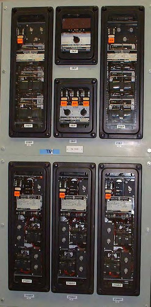
48 Illustrations Of A Lockout Relay CAUTION NEVER HOLD THESE RELAYS IN THE RESET POSITION this can burn up the operate coil and make the relay useless! RESET TRIPPED 48
49 Relay Basics Exercises / Review
50 The purpose of relay protection is to detect and isolate faulted equipment to: 1) Limit extent of disturbance 2) Preserve customer service 3) Maintain reliability 1. 1 and and and 3 50
51 One of the primary functions of protective relays is to ensure continuity of service to customers. A. True B. False 51
52 What parameters are used as inputs to relays? Rank Responses
53 Relays convert system parameters into electrical signals and when these signals reach a set point, the relay: A. Initiates a trip B. Waits for operator instructions C. Triggers an alarm D. Resets its counter 53
54 What is a desirable characteristic of relay systems? Rank 1 Responses
55 A. CTs B. PTs C. BLTs D. Wavetraps Which of the following are input devices for relay schemes? 55
56 In most applications, current transformers scale down full load currents to a value of: A. 1 ampere B. 2 amperes C. 4 amperes D. 5 amperes 56
57 In most applications, potential transformers reduce primary system voltage to approximately: A. 100 volts B. 115 volts C. 208 volts D. 240 volts 57
58 A. 40 B. 80 C. 100 D. 200 How many turns would be required on a CT to achieve the 5 amp relay current if the full load current was 400 amps? PJM /8/2015
59 Current and voltage quantities can be combined in a relay circuit to determine the impedance of a line. A. True B. False 59
60 Which of the following are major design classifications of relays: A. Electromechanical B. Solid State C. Virtual D. Microprocessor based 60
61 Transmission Line Protection
62 Transmission Line Protection A typical power system utilizes three types of lines to deliver power to the end user. They are: 1) Transmission Lines 2) Sub transmission Lines 3) Distribution Lines We will be focusing on the Transmission lines which are defined as lines operating at 100kv and above 62
63 Transmission Line Protection Because these lines carry large amounts of energy and are extremely important to the operation of a power system, it is necessary to use the most advanced relaying methods to insure their integrity Being that important, it is desirable to have instantaneous clearing for all faults on the transmission line under normal operating conditions 63
64 Quick Review A Transmission Line has Impedance (Z) that is composed of resistance (R) and Reactance (X) It can symbolically be represented as: Z = R +j X Consequently, on an R X impedance diagram, any line can be graphically represented See example 64
65 Graphical Representation of a Line Impedance Sub A Inductive Reactance Sub B Inductive Reactance Sub B Line Angle Shunt Capacitance For Overhead Lines, this can generally be ignored. Sub A Resistance 65
66 Transmission Line Protection For reliability, transmission lines utilize Primary and Backup protective schemes The criticality of each line is evaluated to determine if backup protection should be equivalent to primary protection. The factors which influence the decision are: System Stability Concerns Relay Coordination Concerns 66
67 Transmission Line Protection System Stability If stability studies indicate that delayed clearing of faults on a transmission line cause a Generator to go unstable, it indicates that both the primary and backup protective schemes must clear all faults instantaneously These studies are done as part of the initial engineering process 67
68 Transmission Line Protection Relay Coordination: If protection studies determine that coordination of backup relay schemes can not be achieved, dual pilot protection schemes must be employed on the line to be protected Typically happens on Long Line/Short Line situations. See example 68
69 Relay Coordination: Long Line/Short Line Long Line (some R+jX) Short Line (some R+jX) Sub A X Sub B Sub C C Sub B Required Zone 1 relay. B Sub A Required Zone 2 relay. A R Miscoordination exists because Zone 2 of Sub A overreaches Zone 1 of Sub B. 69
70 Primary Transmission Line Protection To obtain instantaneous clearing for all faults, Pilot Relaying is utilized The term pilot implies that a communication channel exists between all terminals of the protected line Power Line Carrier Telephone pair Fiber Optic Microwave 70
71 Primary Transmission Line Protection Several types of pilot protection schemes exist. The ones we will review are: 1) Directional Comparison 2) Direct Under reaching Transferred Trip 3) Permissive (Over & Under reaching) 4) Phase Comparison 5) AC Pilot Wire 6) Optical Fiber Differential 71
72 Logic Gates Overview A B A B AND Gate Needs 2 inputs to get an output Output OR Gate Needs 1 input to get an output Output A B Output A B Output NOT Gate Output is the inverse of the input A A Output Output 72
73 Directional Comparison Blocking Relays set to see beyond remote terminals Under non fault conditions, no signal is sent between the terminals of the line To initiate a breaker trip, two conditions must be met: Operation of a local tripping relay AND Absence of a blocking signal from remote end Testing of communication path is done by Carrier Checkback Scheme 73
74 Directional Comparison Blocking Scheme To Initiate Trip: Over reaching Relay must operate Absence of Blocking Signal from remote end In digital logic: Over reaching Relay Blocking Signal AND Trip Invert AND: Needs two high inputs in order to provide an output 74

75 Directional Comparison Blocking 75

76 Wave Trap and CCVT Illustration Of 500kV Wave Trap & CCVT Wave Trap The carrier signal couples to the transmission line through the CCVT The signal enters and exits the base of the CCVT, then connects to a nearby impedancematching tuning box and then to the transmitter/receiver equipment located inside the substation control house CCVT The carrier signal traffic is bi directional: the local terminal both transmits a signal to the remote terminal and receives a signal from it, all through the same path shown in the illustration The wave trap blocks the carrier signal from exiting the transmission line through any path other than through the CCVT 76


77 Typical Blocking Carrier Controls Carrier Test Switch Received Signal Meter Carrier Blocking Switch Note the red yellow green segments on the Received Signal Meters the received carrier signal is strong enough if it appears in the green region, so so in the yellow region, and bad enough to warrant blocking the carrier relaying if in the red region 77
78 Direct Under reaching Transfer Trip Relays set to under reach the remote terminal Under non fault conditions, a continuous GUARD signal is sent by the local transmitter and monitored by the remote receiver To initiate a breaker trip, one of the following must occur: Local under reaching relay must operate OR Reception of a TRIP signal from the remote end must e received Testing of communication path is continuous via GUARD signal. Loss of guard will generate alarm 78
79 Direct Under reaching Transfer Trip Scheme To Initiate Trip: Under reaching Relay must operate OR Receive a trip signal from the remote end In digital logic: Under reaching Relay Trip Signal from Remote End OR Trip OR: Needs one high input in order to provide an output 79
80 Direct Under reaching Transfer Trip 80
81 Permissive Under reaching Transfer Trip Direct tripping relays set to under reach remote end Fault detector relays set to overreach remote end Under non fault conditions, continuous GUARD signal is sent to remote end To initiate a breaker trip, one of the following must occur: The under reaching relay must operate OR The overreaching relay must respond AND a TRIP signal must be received from remote end Communication path testing is continuous via GUARD signal. Loss of Guard will generate an alarm 81
82 Permissive Under reaching Transfer Trip Scheme To Initiate Trip: Under reaching Relay must operate OR Over reaching relay must operate AND receive a trip signal from the remote end In digital logic: Over reaching Relay Trip Signal from Remote End AND Under reaching Relay OR Trip 82

83 Permissive Under reaching Transfer Trip 83
84 Permissive Over reaching Transfer Trip Relays set to see beyond remote terminals Under non fault conditions, a continuous GUARD signal is sent To initiate a breaker trip, two conditions must be met: Operation of local tripping relay AND Receipt of TRIP signal from remote end Testing of communication path is continuous via GUARD signal. Loss of Guard generates alarm 84
85 Permissive Over reaching Transfer Trip To Initiate Trip: Over reaching Relay must operate AND Receive a trip signal from the remote end In digital logic: Over reaching Relay Trip Signal from Remote End AND Trip 85
86 Permissive Over reaching Transfer Trip 86


87 TRIP Received Lamp GUARD Received Lamp MAINT SWITCH To Key TRIP For Radial Line Operation Illustrations Of Typical POTT Scheme Indications and Controls Example Of Clearly Labeled Indications and Controls On a POTT Control Panel 87
88 Phase Comparison This is a differential scheme that compares the phase angle difference between the currents at the terminals of a transmission line If currents are in phase, no fault is present on this line section If currents are out of phase by about 180 degrees, an internal fault is present Equipment used is same as Directional Comparison scheme Scheme was typically used on the 500 kv system 88
89 Phase Comparison Relaying CT's A WAVE TRAP F2 WAVE TRAP B CT's F3 COUPLING CAPACITOR COUPLING CAPACITOR MIXING NETWORK AND LEVEL DETECTOR COMPARER COMPARER MIXING NETWORK AND LEVEL DETECTOR TRANS- MITTER RECEIVER RF CHOKE RF CHOKE RECEIVER TRANS- MITTER 89
90 AC Pilot Wire Form of differential line protection where phase currents are compared to determine if a fault is internal or external to the protected line segment (similar to phase comparison) Requires a pair of wires between terminals to operate. Economical for short lines Operation is similar to a bus or transformer differential scheme Loss of two wire pair will defeat tripping scheme. No automatic testing of P.W. exists 90
91 Pilot Wire Relaying (Current Differential) Sub A Sub B A B Restraint Restraint Mixing Network V A Insulating Transformer Pilot Wires Insulating Transformer V B Mixing Network Operating Operating 91
92 Optical Fiber Differential Relays operate on a current differential basis Requires the use of optical fiber to transit digital information The digital information contains the current magnitudes and other diagnostic parameters and is transmitted continuously between connected stations Tripping is initiated when differential relay exceed the relays restraint characteristic Failure of the fiber communication path will automatically block the scheme and initiate an alarm 92
93 Backup Transmission Line Protection Can be exactly like primary protection. Depends upon stability or coordination concerns If stability and coordination are not a concern, non pilot relaying can be applied as a backup scheme 93
94 Backup Transmission Line Protection In non pilot applications, line protection generally consists of the following: Stepped Distance for Phase Protection Directional Time and Instantaneous Overcurrent for Ground Protection Due to the recent introduction of microprocessor based relays, additional relay functions are available for use. The more common functions include: Ground Stepped Distance elements Negative Sequence Overcurrent elements 94
95 Backup Transmission Line Protection Directional Overcurrent Ground Relay Equipped with Time & Instantaneous elements Time Element must be coordinated with other ground relays in the system Instantaneous relays must be set short of remote terminal (just like Zone 1 phase relays) Non directional relays can also be applied if they can be coordinated. However, with the new microprocessor relays, directionality is available so might as well use it Aids in coordination 95
96 Backup Transmission Line Protection Directionality how is it achieved? The directional unit of a relay uses the current from the line being protected (i.e. phase current for a phase relay and residual current for a ground relay) in conjunction with a polarizing quantity to determine power flow direction The polarizing quantity is typically voltage 96
97 Other Functions Performed: When either a primary or backup relay responds, the relay scheme will initiate: 1) Tripping of the line terminal CB(s) 2) Stop sending carrier blocking, send trip signal, etc. Depends upon relay scheme 3) Initiate Breaker failure relay scheme/dtt 4) Automatic reclosing (if applicable) 97
98 Breaker Failure Relaying Short Discussion If a stuck breaker condition occurs, a breaker failure scheme will be initiated that will trip the necessary local CBs needed to isolate the failed CB In addition, Direct Transfer Trip may be initiated to trip any remote CBs that could supply the fault. DTT will temporarily block auto reclosing If the failed CB can be automatically isolated by the opening of motor operated disconnects, this will occur and allow reclosing of remote CBs. If there are no MOD s, reclosing remains blocked 98
99 Breaker Failure Relaying Short Discussion Direct Transfer Trip Can be used for the following purposes: Insure tripping of remote terminal for transformer faults Clear the remote terminal for stuck breaker condition at the local station Generally, high security is achieved by using two transmitter/receiver pairs To initiate a trip, both receivers must detect their unique trip signal from the respective transmitter 99
100 Reclosing Practices Just as it is advantageous to clear a fault as fast as possible to minimize the shock to the electrical system, it is also advantageous to return the transmission path to service as soon as possible Since most faults on transmission lines are transient in nature (i.e. disappear when circuit is de energized), automatic reclosing provides the means for returning the power system to a more stable state 100
101 Reclosing Practices On the 230 kv system, multi shot reclosing may be employed. However, this can differ among PJM member companies On the 500 kv system, it is a standard policy to utilize single shot reclosing for lines. The reclosure attempt will take place 5 seconds after the line trips 101
102 Reclosing Practices Where is automatic reclosing not desirable? 1) If protected line is an underground cable 2) If line has a tapped transformer that cannot be automatically disconnected from the line 3) If line is just being returned to service and trips All situations are usually taken care of by the control scheme during design stage 102
103 Reclosing Practices Manual Reclosing This includes supervisory (SCADA) control in addition to control handle closures Used when switching equipment in or out of service. (SCADA is typically used instead of control handle in order to confirm its availability Should fault occur as soon as a CB energizes a piece of equipment, no automatic reclosing will take place 103
104 Reclosing Practices Manual Reclosing Also used for Try Back (testing) of a line after a fault Company policy should be followed when fault testing is being considered The operator should consider the effects that testing may have on the electrical system (shocking the system again) If possible, it is always better to request a patrol of line before trying to restore it to service 104
105 Reclosing Practices In general, reclosing of transmission line CBs is supervised by Synchro check relays Insures that the two systems being ties together are in synchronism with each other (or close to it) If the systems are synchronized such that the angle between the two are within defined limits, reclosing will occur. If they are outside the predefined limits, the relay will block reclosing 105
106 Protective Relay Alarms Via SCADA Depending upon design, receiving of an alarm could mean: 1) Low signal levels on Power Line Carrier Equipment 2) Loss of Guard on one or more Permissive or DTT schemes 106
107 Risks Involved Directional or Phase Comparison Schemes With low signal levels, there is a good chance that the protected line could overtrip for a fault Permissive Transferred Trip Schemes With a continuous loss of guard, the scheme will shut itself down. Little risk of overtripping exists With a sporadic loss of guard, noise is being introduced into communication channel. Fair chance of incorrect tripping exists Momentary loss of guard and return to normal has little risk of overtripping 107
108 Risks Involved Direct Transfer Tripping Schemes A continuous loss of guard will shut down scheme. Little risk of overtripping exists Sporadic loss of guard is indication of noisy communication channel. There is a good chance that an overtrip will occur Momentary loss of guard and return to normal is of little concern. Low risk of overtripping 108
109 Ranking of Risks (Most to Lease Critical) 1) Sporadic Loss of Guard Direct Transferred Trip Schemes 2) Low Signal Levels Directional or Phase Comparison 3) Sporadic Loss of Guard Permissive Transferred Trip Schemes 4) Continuous Loss of Guard Direct Transferred Trip Schemes 5) Continuous Loss of Guard Permissive Transferred Trip Schemes 6) Momentary Loss of Guard Direct Transferred Trip Schemes 7) Momentary Loss of Guard Permissive Transferred Trip Schemes 109
110 Special Relay Schemes Load Shedding via Underfrequency Close In Fault Protection 110
111 Underfrequency Load Shed Used to match load with available generation In this program, PJM Member companies must shed 30% of their base load. Done in 10% steps UF load shedding is coordinated with UF relays at generating stations 111
112 Close in Fault Protection In service for a short period of time after a transmission line has been re energized (i.e. one terminal closed) Simple instantaneous overcurrent relays are utilized to trip the line if a fault (i.e. grounds) exist on the line. The relays are removed from service after a short time delay 112
113 Transmission Line Protection Exercises/Review
114 The two categories of relay schemes commonly used for transmission line protection are: A. Stepped distance & Overcurrent B. Pilot based and Overcurrent C. Pilot based and Stepped Distance D. Under voltage and Overcurrent 114
115 Distance relay schemes employ Ohm s law and divide what two quantities to obtain line impedance? A. Voltage/Resistance B. Voltage/Current C. Current/Resistance D. Current/Voltage 115
116 What is the primary disadvantage of Stepped time distance relay scheme? A. Doesn t cover the entire line B. Delayed clearing for certain faults C. No overlapping zones of protection D. Lack of coordination 116
117 Identify a means of communication used in pilot relay schemes. A. Microwave B. Telephone pair C. Power Line Carrier D. Fiber Optic PJM /8/2015
118 One of the primary advantages of using an impedance (distance) relay for backup transmission line protection rather than overcurrent relay is: A. It has a constant reach B. There is no time delay C. Not susceptible to load current trips D. Non directional protection 118
119 Which of the following are features of Stepped Time Distance relay schemes? 1. Uses Impedance relays 2. Relays are directional 3. All relays have a small time delay 4. Relays are typically grouped in three zones A. 1, 2 and 3 B. 1, 2 and 4 C. 1, 3 and 4 D. 2, 3 and 4 PJM /8/2015
120 A Zone 1 impedance relay is set on both ends of the line and allows instantaneous tripping to protect what percentage of the line? A. 100% B. 90% C. 75% D. 50% PJM /8/2015
121 Pilot relay schemes allow instantaneous tripping for what percentage of the protected line? A. 100 % B. 90% C. 75 % D. 50% PJM /8/2015
122 Directional Phase Comparison schemes protect for a fault on the line because the fault will cause what? A. Max current flow out of the line B. Current flow at both ends into the fault C. High voltage spikes in the fault area D. Voltage flow towards the fault 122
123 Relay Testing Considerations and Concerns
124 Relay Testing Relay testing is important to insure Relays and Relay Schemes are functioning as designed Because testing is usually done when primary equipment is energized, there is a risk that unwanted operation of relay schemes may occur 124
125 Why can tripping occur? Close working conditions Wiring errors Improper Blocking or Isolating of equipment Inexperience (lack of training) Accidental (bump panel or relay) 125
126 Considerations and Concerns for S.O. s: When a request is received from a person doing testing, think about: What could it do to the system? Is the system being operated in a manner that the loss of the equipment protected by the relay scheme will cause serious problems (stability, voltage, overloads etc.) Would the removal of relay scheme go beyond the setting criteria for other relay schemes 126
127 Protection Practice: Protection and Coordination are typically based upon the electrical system being normal or altered by any single contingency A single contingency is the outage of a piece of equipment such as a line, transformer or relay scheme If more than one piece of equipment is outaged at a station, protection or coordination can be compromised The relay engineers should be contacted to insure protection and coordination will still exist 127
128 General Considerations for Dispatchers Following a Relay Operation
129 Know your companies policy regarding Dispatcher response to a relay trip Who do you notify? Who to call to initiate repairs Who to call to perform line patrols, substation inspections, etc. Inter company response & notifications 129
130 Data collection and fault analysis Try to obtain as much data as possible for future detailed analysis (i.e. relay targets, Digital fault recorder information, system conditions) Real time analysis comes with experience Often knowing what has tripped may lead to a determination of the faulted piece of equipment or potential relay problem (See examples) 130
131 Fault analysis Breakers 1 thru 7 trip open. Where is the likely fault location? 131
132 Fault analysis 132
133 Exercise prudence before Trying Back 500 kv lines have a single shot reclosing attempt after 5.0 seconds Testing after 5 minutes is possible with concurrence from PJM and others No Try Back should occur on: 1) Generator SU transformers 2) Underground Cable (Bus Work) 3) Indoor equipment 133
134 Transformer Protection
135 Transformers: At the heart of the Transmission System They make the transport of large amounts of electrical energy economically possible Because of their criticality to the Bulk Power System, high speed clearing for faults is desirable 135
136 Transformer Protection Typical Problems that can occur: Inside the Tank 1) Winding Faults to Ground 2) Winding Turn to Turn Shorts 3) Excessive Winding and/or Oil Temperature 4) Overloads (i.e. winding/oil temperature External to Tank 1) Bushing Lead Failure 2) Bushing Flashover 3) Lightning Arrester Failure 4) Through Faults 136
137 Transformer Protection Transformer Protection is typically provided by differential relaying Transformers provide unique problems for differential relaying that must be accounted for: 1) Different voltage levels (i.e. different current magnitudes) 2) Automatic Tap Changers (LTC s or TCUL s) associated with transformers cause further mismatch between high side and low side currents 3) Energizing a transformer causes magnetizing inrush current which appears as an internal fault to the differential relay 4) Because of Delta Wye connections, the transformer introduces a 30 degree phase angle shift that must be accounted for 137

138 CT Connections for Tapped Transformer 138
139 CT Connections for Bus Connected Transformer 139
140 Transformer Protection It was recognized early that a perfect match of CT ratios, necessary for the differential relay, was practically impossible Mismatch of CT secondary currents can be overcome with a Percentage Differential Characteristic relay This type of relay has operate and restraint coils which are connected in a manner that allows for a certain amount of CT mismatch 140
141 Transformer Protection The inrush current that exists when a transformer is energized is high in harmonics, particularly the second harmonic The use of a Harmonic Restraint element can de sensitize the differential relay to these harmonics and provide the necessary security required 141
142 Inrush Current Applied Voltage Typical Magnetizing Inrush Current Wave Typical Offset Fault Current Wave 142
143 Transformer Protection The 30 degree phase shift that is introduced when protecting wye delta transformer banks can be overcome with the proper connection of the CTs supplying the differential relay The general rule of thumb: CTs on wye side of transformer should be connected in delta, while CTs on the delta side should be connected in wye 143
144 Transformer Protection Bottom Line: The differential relay is the ideal device for transformer protection in that it takes advantage of the zone type of protection to provide sensitive high speed clearing of transformer faults 144
145 Transformer Protection Since high voltage transformers are critical to the Bulk Power System, generally primary and back up differential relays are used for protection Beyond using two discrete differential relays, additional devices are used to protect the transformer 145
146 Transformer Protection Sudden Pressure Relays: If an arcing fault occurs inside the transformer tank, gases are generated which can be detected by a pressure relay Operation of this relay will initiate tripping of the transformer This protection provides back up to the differential relays 146
147 Transformer Protection Gas Analyzers (Combustible Gas Relay): Low magnitude faults produce gases as they breakdown the oil and insulation in the transformer tank The gas analyzer relay constantly monitors the gas space above the transformer oil and will actuate an alarm if gas levels exceed a predetermined level An Alarm provides warning of a possible internal fault which could be catastrophic 147
148 Transformer Protection Winding Temperature Relays: Winding Temperature (referred to as Hot Spot protection) inside the transformer is simulated by using a CT to drive a heating element under oil As the transformer becomes loaded, the heating element produces more heat As the heat increases and predetermined temperature levels are reached, a temperature sensing device will: 1) Start additional cooling groups (if possible) 2) Alarm if temperature continues to increase 3) Trip the transformer 148
149 Transformer Protection Oil Temperature Relays: Oil temperature is monitored by a Top Oil device inside the tank. Similar to the Hot Spot protection, when predetermined temperature levels are reached, a temperature sensing device will: 1) Start additional cooling groups (if possible) 2) Alarm 3) Trip the transformer 149


150 Illustrations Of Analog Gauge Style Winding Temperature and Liquid Temperature Thermal Devices 150

151 Illustration Of Microprocessor Based Thermal Device Liquid Temperature is the upper unit Winding Temperature is the lower unit 151
152 Transformer Protection Transformer Neutral Overcurrent Relay: Relay is connected to a CT located on the neutral connection of a WYE Grounded transformer Used as Back Up protection for Through Faults Must be coordinated with other system ground relays Operation of this relay will trip the transformer 152
153 Transformer Protection Blind Spot Overcurrent Relay: On occasion, tapped transformers are energized from the low side only (i.e. high side MOAB is open). This is typically done to maintain station service Line Relaying may not respond to a fault that could occur between the Transformer Diff. CTs and the MOAB A Blind Spot relay is used to detect this condition It is in service only when the high side MOAB is open Will trip the low side circuit breakers to isolate the fault 153
154 CT Connections for Tapped Transformer Fault 154
155 Transformer Protection Other Protective Devices: Loss of Cooling Relay If all fans and/or oil pumps are lost for any reason, the transformer will be tripped if temperature is above a predetermined level Low Oil Level Lack of proper oil level compromises transformer cooling. This device will alarm and eventually trip the transformer if oil level drops below a certain threshold 155
156 Transformer Protection Operation of any of the above relay schemes will initiate other protective functions The physical design of the electrical system will define what additional actions are taken Some actions include: 1) Initiate Direct Transferred Trip to remote terminals 2) Initiate breaker failure relaying 3) Block reclosing of CBs that are tripped (until transformer is isolated) 4) Close the high speed ground switch 5) Initiate permissive trip/stop sending blocking signal, etc 156
157 Transformer Protection Turn to Turn shorts (non fault condition) Have not discussed this abnormal condition much In general, this condition is very difficult to detect initially As more and more insulation deteriorates, this condition may cause the gas analyzer relay to respond Otherwise, could go undetected until winding flashes over to ground. At that point, normal transformer protection will respond to clear the fault 157
158 Transformer Protection Because a Bulk Power Transformer is a high cost piece of equipment, automatic testing of the transformer is generally not included in the control scheme design If the differential relay responds, a master trip auxiliary relay will trip and block closing of devices which could re energize the transformer To reclose the locked out devices, this master trip relay must be hand reset 158
159 Operator s role if Transformer Protection Operates Know your company policy! Alert all that need to be informed of the operation Be aware of steps required to alleviate possible system overloads, low voltage concerns, etc. In general, do not test (try back) the transformer until it is inspected by qualified individuals 159
160 Bus Protection
161 Typical Bus Designs Single Bus Single Breaker Least flexible of sub designs, but low cost Ring Bus Improved Flexibility, may be difficult to relay. Breaker and a Half Offers most flexibility, but more expensive Double Bus Double Breaker Similar to Breaker and a Half 161
162 Single Bus Single Breaker Arrangement 162
163 Ring Bus Arrangement 163

164 Breaker and a Half Bus Arrangement 164

165 Double Breaker Double Bus Arrangement 165
166 Bus Protection On the Bulk Power System, the most common protection practice to insure high speed clearing of faults on bus work is to use Differential Relays Older, less critical stations may employ Time and Instantaneous Overcurrent relays connected in a differential scheme. These schemes can be less sensitive, slower or both 166
167 Bus Protection Generally, the CTs used for Bus Protection are located on the line or equipment side of the circuit breaker. Consequently, the CB is within the protection zone of the bus differential and the line or piece of equipment (overlapping zones of protection) CTs that are connected in the differential scheme should be of an accuracy class that can withstand maximum expected fault currents (i.e. CTs should not saturate). Failure of application engineers to insure this could lead to a misoperation 167
168 Bus Protection If a bus differential relay operates, the relay will typically do the following: 1) Energize a Master Trip Auxiliary Relay 2) Trip all sources to that bus section (via the Master Trip) 3) Setup the Reset of the Master Trip Relay if bus testing is to occur 4) Block reclosing of all CBs except that of the automatic testing source (if so equipped) 5) Initiate Breaker Failure 6) Initiate an Alarm 168
169 Bus Protection On the 500kv System, automatic bus testing does not occur In general, on voltage levels below 500kv, a single automatic test of the bus might occur. This can vary across the PJM territory 169
170 Bus Protection If the particular station is equipped with bus testing and a successful test occurs, all remaining CBs that were tripped will automatically reclose If the bus test was unsuccessful, all CBs, including the testing CB, will be locked out Although automatic reclosing is blocked, the operator may have the ability to close a CB via supervisory control (SCADA) 170
171 Operator Role is Bus Protection Operates to de energize a Bus Know your company policy! Alert all that need to be informed of operation Be aware of steps required to alleviate possible system overloads, low voltage concerns, etc. (sound familiar?) If the bus trips and locks out, no testing via SCADA should occur until the station is inspected by authorized personnel 171
172 Direct Transferred Trip (DTT) Relaying
173 Clearing Sequence For A Fault On Brunner Island Transformer 20 WEST HEMPFIELD 230/69 kv SUB BRUNNER ISLAND 230 kv PLANT and SWITCHYARD 230 kv CB West Hempfield East 230 kv GCB T20 MOD T20 HSGS 230/13.8/4 kv Transformer 20 To 13.8 kv and 4 kv Lowside CBs inside Plant 69kV CB West Hempfield West 230 kv GCB
174 1) A fault occurs inside Transformer 20 at Brunner Island WEST HEMPFIELD 230/69 kv SUB BRUNNER ISLAND 230 kv PLANT and SWITCHYARD 230 kv CB West Hempfield East 230 kv GCB T20 MOD T20 HSGS 230/13.8/4 kv Transformer 20 To 13.8 kv and 4 kv Lowside CBs inside Plant 69kV CB West Hempfield West 230 kv GCB
175 2) At Brunner Island, Transformer 20 protection operates to immediately trip the West Hempfield East and West 230kV circuit breakers and the 13.8kV and 4kV Transformer 20 lowside circuit breakers. Simultaneously, a DTT TRIP signal is initiated to West Hempfield Sub, the T20 HSGS closes and the T20 MOD starts to open 3) At West Hempfield, the 230kV line and 69kV transformer lowside breakers open immediately upon receipt of the DTT TRIP signal all circuit breakers at West Hempfield are open before the HSGS at Brunner Island closes fully into the transmission line WEST HEMPFIELD 230/69 kv SUB BRUNNER ISLAND 230 kv PLANT and SWITCHYARD 230 kv CB West Hempfield East 230 kv GCB T20 MOD T20 HSGS 230/13.8/4 kv Transformer 20 To 13.8 kv and 4 kv Lowside CBs inside Plant 69kV CB West Hempfield West 230 kv GCB
176 4) At Brunner Island, the T20 MOD opens fully to physically isolate the fault and stops the DTT TRIP signal to West Hempfield all circuit breakers at West Hempfield reclose automatically. The transmission line breakers at Brunner Island also reclose automatically after the failed transformer is isolated, but the T20 lowside breakers are designed to stay open. WEST HEMPFIELD 230/69 kv SUB BRUNNER ISLAND 230 kv PLANT and SWITCHYARD 230 kv CB West Hempfield East 230 kv GCB T20 MOD T20 HSGS 230/13.8/4 kv Transformer 20 To 13.8 kv and 4 kv Lowside CBs inside Plant 69kV CB West Hempfield West 230 kv GCB
177 Bus Protection
178 Illustration Of Automatic Bus Testing In a Transmission Switchyard Following a bus differential operation, a preselected circuit breaker automatically recloses to test the bus
179 Illustration Of Automatic Bus Testing In a Transmission Switchyard Following a bus differential operation, a preselected circuit breaker automatically recloses to test the bus
180 Illustration Of Automatic Bus Testing In a Transmission Switchyard If the bus test is unsuccessful, all circuit breakers lock out and must be closed manually or by SCADA
181 Illustration Of Automatic Bus Testing In a Transmission Switchyard On the other hand, if the bus test is successful, all the other circuit breaker automatically reclose after a time delay to ensure the bus is stable.
182 Bus Testing At Generating Stations Automatic bus testing following a bus differential operation at a generating station is given special consideration because of the severe mechanical stresses placed on turbine-generator couplings by a close-in bus fault normally the impedance between the generator terminals and a fault on a power line cushions the mechanical impact on the turbine-generator a bus fault, however, is essentially right at the terminals of the GSU transformer, so we want to limit exposure of the generator to such close-in faults as much as possible for this reason, a tripped bus at a generating station should be tested only with a transmission line energized from a remote substation this technique puts the testing source as far away as possible so that the impedance of the transmission line limits the current available to a persistent bus fault and thus minimizes added stress on the local generators
183 Illustration Of Automatic Bus Testing At a Generating Station G G G Following a bus differential operation, a preselected circuit breaker must be closed to test the bus which one is preferred here and why?
184 Transformer and Bus Protection Exercises/Review
185 The most commonly used relay scheme for transformer and bus protection is: A. Overcurrent B. Undervoltage C. Differential D. Distance PJM /8/2015
186 Differential relay schemes compare the total current flowing into a device to. A. A reference current B. Total current leaving the device C. Total voltage drop across the device D. Voltage flow through the device 186
187 A differential relay scheme across a transformer must compensate for. A. Voltage ratio across the transformer B. Impedance ratio of the transformer C. Current ratio across the transformer D. Resistance ratio of the transformer 187
188 Automatic reclosure availability on some relay schemes serves to improve overall reliability by restoring circuits after a fault has been cleared. A. True B. False 188
189 Generator Protection
190 D. C. Excitation System Prime Mover Generator Generator Step Up Transformer Synchronizing CB System Aux. Load Emergency Diesel Generator Start Up Transformer High Voltage Bus Typical Generating Plant Arrangement 190
191 Station Arrangement A Generator is usually connected to the power system through a wye delta transformer (wye on the high voltage side, delta on the generator side) Generator itself is connected wye with its neutral grounded through a high impedance Purpose of this generator connection is to limit the high magnitude currents which could flow for a ground fault 191
192 Station Arrangement Generator In Service Startup Transformer is out of service Plant auxiliary loads are supplied from the station service transformer Generator Out of Service Since Generator is off line, the station service transformer is out of service Plant auxiliary loads are supplied from the Startup Transformer 192
193 Station Arrangement Station Blackout Generator has just tripped or was already off line The startup transformer can provide no help because this portion of the high voltage system is interrupted Emergency generators (diesel) are used to supply the plant auxiliary load until the system is restored 193
194 Generator Unit Tripping
195 Generator Unit Tripping: The frequency of failures in Rotating Machines is low, however failures can and do occur Beyond actual failures, certain abnormal conditions can cause generator failure if not corrected quickly Some of these harmful conditions are: Winding Faults Overheating Loss of Field Single Phasing Overloading Overspeed Motoring (turbine) Overexcitation 195
196 Generator Unit Tripping: Not all of the problems mentioned necessarily have to cause a unit trip. If detected quickly, measures can be taken to mitigate the problem Consequently, some relay schemes will first produce an alarm to alert operators of the problem. If the problem worsens before corrective action can be taken, the scheme will initiate a unit trip 196
197 Generator Unit Tripping: If protective devices do cause a unit trip, the following actions will occur: 1) Generator Synchronizing CB is tripped and locked out 2) Normal Station Service supply CB is tripped 3) Generator DC field CB is tripped 4) Prime Mover is tripped 197
198 Generator Unit Tripping: When a unit trips, the function of the plant operator is to stabilize the prime mover and auxiliary systems to insure a controlled shut down The generation dispatcher s purpose is dependent upon individual company procedures. This could involve negotiation for additional generation or notifying that company s energy marketing function 198
199 Overall Unit Protection
200 Areas to be protected and concerns: 1) Generator Winding Fault, Overloading, Overheating, Overspeed, Underfrequency, Loss of Excitation, Motoring, Phase Unbalance, Out of Step 2) Turbine Overspeed, Underspeed, Vibration, Temperature 3) Auxiliaries Cable Faults, Grounds on System 4) Station Service Transformer Faults, Lead faults, etc 200
201 Ground Relay R To Excitation System Unit Differential Relay Generator CB D.C. Field R Distribution Transformer GEN R Generator Differential Relay Xfmer Diff. Relay R Main Power Transformer Station Bus Protection Station Service Load Station Service Transformer Station Service Bus Start Up Transformer Start Up CB R Station Service Bus Differential Relay Xfmer Diff. Relay R 201
202 Protective Relay Schemes for the Generator: Generator Differential Wraps only the Stator Windings of the Generator Sensitive to phase and some ground faults Operation of this relay will initiate a unit trip 202
203 Generator Differential C Rotor (DC Field) B A High Impedance Neutral Armature and Stator Windings 87 Differential Relay (B & C Phases are similar) 203
204 Protective Relay Schemes for the Generator: Overall Differential Wraps the Generator, Gen. Step up Transformer & Station Service Transformer Sensitive to phase & some ground faults Backs up the Gen. Diff, GSU Diff., Station Service Diff, etc Less sensitive than the Gen. Diff Operation of this relay will initiate a unit trip 204
205 UNIT DIFFERENTIAL PROTECTION TO GRID SYSTEM TO EXCITATION SYSTEM D.C. FIELD GENERATOR C.B. GENERATOR NEUTRAL TO GROUND 87 GEN. MAIN POWER TRANSFORMER STATION BUS (HIGH VOLTAGE) STATION LOADS STATION SERVICE BUS (LOW VOLTAGE) STATION SERVICE TRANSFORMER TO GRID SYSTEM 205
206 Protective Relay Schemes for the Generator: Overcurrent Protection Provide Backup Protection for Gen. Diff Scheme Protects the generator from system faults that are not cleared within a predetermined time interval Coordinated with System Overcurrent schemes Usually time delayed to minimize tripping for transient surges or synchronizing Will initiate a unit trip 206
207 Generator Other Generator Protection Relays To GSU Transformer CT 51G PT Backup Overcurrent 46 - Negative Sequence 40 - Loss of Field 81 - Underfrequency 32 - Reverse Power (Anti-motoring) 51G - Generator Ground Overcurrent 59 - Overexcitation 207
208 Protective Relay Schemes for the Generator: Anti motoring or Reverse Power Protection: Actually used to protect the Turbine instead of the generator When Generator takes in power, it is essentially a synchronous motor (non harmful to generator) This mode of operation, if sustained could lead to turbine blade failure This is one standard method for taking unit off line May cause alarm, but will initiate a unit trip 208
209 Protective Relay Schemes for the Generator Negative Sequence Protection During unbalanced faults, Negative Sequence currents will flow Physically, 120 cycle rotor currents are induced in the solid rotor forgings, non magnetic rotor wedges and retaining rings. The I 2 R loss quickly raises temperature of the rotor and would eventually cause serious rotor damage Will initiate an alarm and trip unit 209
210 Protective Relay Schemes for the Generator: Generator Ground Fault Protection Method of Generator Grounding affects the protection provided by the differential relays The higher the grounding impedance, the lower the ground fault current magnitude To detect these low magnitude faults, Neutral Overcurrent or an Overvoltage relay scheme is employed Operation of this relay scheme will initiate a unit trip 210
211 Types of Generator Grounding Used Generator Generator 51G Transformer 59 High Resistance Neutral Resistored Neutral with an Overcurrent Relay High Impedance Neutral with Overvoltage Relay 211
212 Protective Relay Schemes for the Generator: Loss of Field Protection When loss of field occurs in a synchronous machine, reactive power flows from the system into the machine The reactive flow can be 2 to 3 times the generators rated load (i.e. thermal damage) Relays monitor reverse var flow or low voltage Operation of this relay will alarm and initiate a unit trip 212
213 Protective Relay Schemes for the Generator: Loss of Field Protection Loss of Field indicates that trouble exists in: 1) Main Exciter 2) Field Winding 3) Operating Error when machine is in Manual mode 213
214 Protective Relay Schemes for the Generator: Overexcitation Protection Concern is for the Generator Field and main GSU transformer since overexcitation can cause damaging overheating due to core saturation in a very short time For GSU transformer protection, a Volts/Hertz relay is applied Operation of relay will trip unit For Field Overexcitation, Voltage or Current relays are employed Relay will alarm or automatically reduce field to allowable limits 214
215 Protective Relay Schemes for the Generator: Underfrequency Protection If System Load exceeds the capability of the machine, the frequency will decay In PJM, machines are typically set for 57.5 hz with a 5.0 second time delay System load shedding schemes are used to dump load as required If not enough load is disconnected and frequency drops, relay will initiate a unit trip If unit tripping occurs, pull out your Black Start Restoration guide because it will be needed! 215
216 Generator Protection Exercises/Review
217 List the associated actions that typically occur when a generator trips: 217
218 Which relay scheme protects the generator from stator winding faults? 1. Loss of field 2. Generator Differential 3. Overspeed 4. Neutral overcurrent 218
219 What type of relay is used to protect the generator from a loss of synchronization resulting from excessive VAR absorption? A. Overexcitation B. Loss of Field C. Negative Sequence D. Differential PJM /8/2015
220 What major component of a generator is protected by a generator field over excitation relay? A. Turbine B. GSU C. Field windings D. Isophase bus PJM /8/2015
221 What is the name of this major component of a generating unit? 221
222 What is the name of this major component of a generating unit? 222
223 What is the name of this major component of a generating unit? 223
224 What is the name of this major component of a generating unit? 224
225 What is the name of this major component of a generating unit? 225
226 What is the name of this major component of a generating unit? 226

227 What is the name of this major component of a generating unit? 227
COPYRIGHTED MATERIAL. Index
 Index Note: Bold italic type refers to entries in the Table of Contents, refers to a Standard Title and Reference number and # refers to a specific standard within the buff book 91, 40, 48* 100, 8, 22*,
PJM Manual 07:: PJM Protection Standards Revision: 2 Effective Date: July 1, 2016
 PJM Manual 07:: PJM Protection Standards Revision: 2 Effective Date: July 1, 2016 Prepared by System Planning Division Transmission Planning Department PJM 2016 Table of Contents Table of Contents Approval...6
PROTECTION SIGNALLING
 PROTECTION SIGNALLING 1 Directional Comparison Distance Protection Schemes The importance of transmission system integrity necessitates high-speed fault clearing times and highspeed auto reclosing to avoid
Transmission Line Protection Objective. General knowledge and familiarity with transmission protection schemes
 Transmission Line Protection Objective General knowledge and familiarity with transmission protection schemes Transmission Line Protection Topics Primary/backup protection Coordination Communication-based
Protection Basics Presented by John S. Levine, P.E. Levine Lectronics and Lectric, Inc GE Consumer & Industrial Multilin
 Protection Basics Presented by John S. Levine, P.E. Levine Lectronics and Lectric, Inc. 770 565-1556 John@L-3.com 1 Protection Fundamentals By John Levine 2 Introductions Tools Outline Enervista Launchpad
Transmission Protection Overview
 Transmission Protection Overview 2017 Hands-On Relay School Daniel Henriod Schweitzer Engineering Laboratories Pullman, WA Transmission Line Protection Objective General knowledge and familiarity with
Sequence Networks p. 26 Sequence Network Connections and Voltages p. 27 Network Connections for Fault and General Unbalances p. 28 Sequence Network
 Preface p. iii Introduction and General Philosophies p. 1 Introduction p. 1 Classification of Relays p. 1 Analog/Digital/Numerical p. 2 Protective Relaying Systems and Their Design p. 2 Design Criteria
System Protection and Control Subcommittee
 Power Plant and Transmission System Protection Coordination Reverse Power (32), Negative Sequence Current (46), Inadvertent Energizing (50/27), Stator Ground Fault (59GN/27TH), Generator Differential (87G),
Protective Relaying Philosophy and Design Guidelines. PJM Relay Subcommittee
 PJM Relay Subcommittee July 12, 2018 Contents SECTION 1: Introduction... 1 SECTION 2: Protective Relaying Philosophy... 2 SECTION 3: Generator Protection... 4 SECTION 4: Unit Power Transformer and Lead
Numbering System for Protective Devices, Control and Indication Devices for Power Systems
 Appendix C Numbering System for Protective Devices, Control and Indication Devices for Power Systems C.1 APPLICATION OF PROTECTIVE RELAYS, CONTROL AND ALARM DEVICES FOR POWER SYSTEM CIRCUITS The requirements
Modern transformer relays include a comprehensive set of protective elements to protect transformers from faults and abnormal operating conditions
 1 Transmission transformers are important links in the bulk power system. They allow transfer of power from generation centers, up to the high-voltage grid, and to bulk electric substations for distribution
Transformer Protection Principles
 Transformer Protection Principles 1. Introduction Transformers are a critical and expensive component of the power system. Due to the long lead time for repair of and replacement of transformers, a major
Transformer Protection
 Transformer Protection Transformer Protection Outline Fuses Protection Example Overcurrent Protection Differential Relaying Current Matching Phase Shift Compensation Tap Changing Under Load Magnetizing
Power systems Protection course
 Al-Balqa Applied University Power systems Protection course Department of Electrical Energy Engineering 1 Part 5 Relays 2 3 Relay Is a device which receive a signal from the power system thought CT and
Texas Reliability Entity Event Analysis. Event: May 8, 2011 Loss of Multiple Elements Category 1a Event
 Texas Reliability Entity Event Analysis Event: May 8, 2011 Loss of Multiple Elements Category 1a Event Texas Reliability Entity July 2011 Page 1 of 10 Table of Contents Executive Summary... 3 I. Event
NERC Protection Coordination Webinar Series July 15, Jon Gardell
 Power Plant and Transmission System Protection Coordination Reverse Power (32), Negative Sequence Current (46), Inadvertent Energizing (50/27), Stator Ground Fault (59GN/27TH), Generator Differential (87G),
Relay Communication Misoperations. Southwest Power Pool System Protection and Control Working Group
 Relay Communication Misoperations Southwest Power Pool System Protection and Control Working Group Relay Misoperations The fundamental objective of power system protection schemes is to quickly provide
Transmission Availability Data System Definitions
 Table of Contents Transmission Availability Data System Definitions February 1, 2018 1 of 31 3353 Peachtree Road NE Suite 600, North Tower Atlanta, GA 30326 404-446-2560 www.nerc.com Table of Contents
OPERATING, METERING, AND EQUIPMENT PROTECTION REQUIREMENTS FOR PARALLEL OPERATION OF LARGE-SIZE GENERATING FACILITIES GREATER THAN 2,000 KILOWATTS
 OPERATING, METERING, AND EQUIPMENT PROTECTION REQUIREMENTS FOR PARALLEL OPERATION OF LARGE-SIZE GENERATING FACILITIES GREATER THAN 2,000 KILOWATTS CONNECTED TO THE DISTRIBUTION SYSTEM ORANGE AND ROCKLAND
OPERATING, METERING AND EQUIPMENT PROTECTION REQUIREMENTS FOR PARALLEL OPERATION OF LARGE-SIZE GENERATING FACILITIES GREATER THAN 25,000 KILOWATTS
 OPERATING, METERING AND EQUIPMENT PROTECTION REQUIREMENTS FOR PARALLEL OPERATION OF LARGE-SIZE GENERATING FACILITIES GREATER THAN 25,000 KILOWATTS AND MEDIUM-SIZE FACILITIES (5,000-25,000KW) CONNECTED
Appendix S: PROTECTION ALTERNATIVES FOR VARIOUS GENERATOR CONFIGURATIONS
 Appendix S: PROTECTION ALTERNATIVES FOR VARIOUS GENERATOR CONFIGURATIONS S1. Standard Interconnection Methods with Typical Circuit Configuration for Single or Multiple Units Note: The protection requirements
A DUMMIES GUIDE TO GROUND FAULT PROTECTION
 A DUMMIES GUIDE TO GROUND FAULT PROTECTION A DUMMIES GUIDE TO GROUND FAULT PROTECTION What is Grounding? The term grounding is commonly used in the electrical industry to mean both equipment grounding
Busbars and lines are important elements
 CHAPTER CHAPTER 23 Protection of Busbars and Lines 23.1 Busbar Protection 23.2 Protection of Lines 23.3 Time-Graded Overcurrent Protection 23.4 Differential Pilot-Wire Protection 23.5 Distance Protection
Electrical Protection System Design and Operation
 ELEC9713 Industrial and Commercial Power Systems Electrical Protection System Design and Operation 1. Function of Electrical Protection Systems The three primary aims of overcurrent electrical protection
System Protection and Control Seminar
 System Protection and Control Seminar Desirable Protection We want to detect a fault within 100% of the zone of protection. We want to avoid interrupting non-faulted zones of protection. We want to clear
NERC Protection Coordination Webinar Series June 9, Phil Tatro Jon Gardell
 Power Plant and Transmission System Protection Coordination GSU Phase Overcurrent (51T), GSU Ground Overcurrent (51TG), and Breaker Failure (50BF) Protection NERC Protection Coordination Webinar Series
Substation Preventive Maintenance
 Substation Preventive Maintenance PROVINCIAL ELECTRICITY AUTHORITY 1 Presentation Contents 1) A kind of substation 2) Electrical equipment details of AIS substation 3) Electrical equipment details of GIS
Transmission System Phase Backup Protection
 Reliability Guideline Transmission System Phase Backup Protection NERC System Protection and Control Subcommittee Draft for Planning Committee Approval June 2011 Table of Contents 1. Introduction and Need
System Protection and Control Subcommittee
 Power Plant and Transmission System Protection Coordination Volts Per Hertz (24), Undervoltage (27), Overvoltage (59), and Under/Overfrequency (81) Protection System Protection and Control Subcommittee
Industrial Electrician Level 3
 Industrial Electrician Level 3 Industrial Electrician Unit: C1 Industrial Electrical Code I Level: Three Duration: 77 hours Theory: Practical: 77 hours 0 hours Overview: This unit is designed to provide
Protection of Electrical Networks. Christophe Prévé
 Protection of Electrical Networks Christophe Prévé This Page Intentionally Left Blank Protection of Electrical Networks This Page Intentionally Left Blank Protection of Electrical Networks Christophe Prévé
Back to the Basics Current Transformer (CT) Testing
 Testing") Back to the Basics Current Transformer (CT) Testing As test equipment becomes more sophisticated with better features and accuracy, we risk turning our field personnel into test set operators instead of
Back to the Basics Current Transformer (CT) Testing As test equipment becomes more sophisticated with better features and accuracy, we risk turning our field personnel into test set operators instead of
Using a Multiple Analog Input Distance Relay as a DFR
 Using a Multiple Analog Input Distance Relay as a DFR Dennis Denison Senior Transmission Specialist Entergy Rich Hunt, M.S., P.E. Senior Field Application Engineer NxtPhase T&D Corporation Presented at
TECHNICAL BULLETIN 004a Ferroresonance
 May 29, 2002 TECHNICAL BULLETIN 004a Ferroresonance Abstract - This paper describes the phenomenon of ferroresonance, the conditions under which it may appear in electric power systems, and some techniques
Detecting and Managing Geomagnetically Induced Currents With Relays
 Detecting and Managing Geomagnetically Induced Currents With Relays Copyright SEL 2013 Transformer Relay Connections Voltage Current Control RTDs Transformer Protective Relay Measures differential current
BUS2000 Busbar Differential Protection System
 BUS2000 Busbar Differential Protection System Differential overcurrent system with percentage restraint protection 1 Typical Busbar Arrangements Single Busbar Double Busbar with Coupler Breaker and a Half
Education & Training
 Distribution System Operator Certificate This program provides you with a proficient working knowledge in modern electric power distribution systems. These four classes are designed to walk students through
2 Grounding of power supply system neutral
 2 Grounding of power supply system neutral 2.1 Introduction As we had seen in the previous chapter, grounding of supply system neutral fulfills two important functions. 1. It provides a reference for the
Generator Protection GENERATOR CONTROL AND PROTECTION
 Generator Protection Generator Protection Introduction Device Numbers Symmetrical Components Fault Current Behavior Generator Grounding Stator Phase Fault (87G) Field Ground Fault (64F) Stator Ground Fault
NOVEL PROTECTION SYSTEMS FOR ARC FURNACE TRANSFORMERS
 NOVEL PROTECTION SYSTEMS FOR ARC FURNACE TRANSFORMERS Ljubomir KOJOVIC Cooper Power Systems - U.S.A. Lkojovic@cooperpower.com INTRODUCTION In steel facilities that use Electric Arc Furnaces (EAFs) to manufacture
Section 6: System Grounding Bill Brown, P.E., Square D Engineering Services
 Section 6: System Grounding Bill Brown, P.E., Square D Engineering Services Introduction The topic of system grounding is extremely important, as it affects the susceptibility of the system to voltage
PIPSPC. Prepared by Eng: Ahmed Safie Eldin. And. Introduction. Protection Control. Practical. System. Power
 PIPSPC Practical Introduction Power System Protection Control Practical Introduction To Power System Protection And Control Prepared by Eng: Ahmed Safie Eldin 2005 Contents POWER SYSTEMS PRINCIPALS. 1
Arizona Public Service Company and the Transmission Partnership for National Electric Power Company of Jordan
 Arizona Public Service Company and the Transmission Partnership for National Electric Power Company of Jordan Mark Hackney October 5-8, 2009 Amman, Jordan Energy Control Center Layout 2 Energy Control
Power System Protection Manual
 Power System Protection Manual Note: This manual is in the formative stage. Not all the experiments have been covered here though they are operational in the laboratory. When the full manual is ready,
Summary Paper for C IEEE Guide for Application of Digital Line Current Differential Relays Using Digital Communication
 Summary Paper for C37.243 IEEE Guide for Application of Digital Line Current Differential Relays Using Digital Communication by: Neftaly Torres, P.E. 70 th Annual Conference for Protective Relay Engineers,
NERC Protection Coordination Webinar Series June 23, Phil Tatro
 Power Plant and Transmission System Protection Coordination Volts Per Hertz (24), Undervoltage (27), Overvoltage (59), and Under/Overfrequency (81) Protection NERC Protection Coordination Webinar Series
Earth Fault Protection
 Earth Fault Protection Course No: E03-038 Credit: 3 PDH Velimir Lackovic, Char. Eng. Continuing Education and Development, Inc. 9 Greyridge Farm Court Stony Point, NY 10980 P: (877) 322-5800 F: (877) 322-4774
E N G I N E E R I N G M A N U A L
 1 1 1.0 PURPOSE The purpose of this document is to define policy and provide engineering guidelines for the AP operating companies (Monongahela Power Company, The Potomac Edison Company, and West Penn
Notes 1: Introduction to Distribution Systems
 Notes 1: Introduction to Distribution Systems 1.0 Introduction Power systems are comprised of 3 basic electrical subsystems. Generation subsystem Transmission subsystem Distribution subsystem The subtransmission
NERC Protection Coordination Webinar Series June 16, Phil Tatro Jon Gardell
 Power Plant and Transmission System Protection Coordination Phase Distance (21) and Voltage-Controlled or Voltage-Restrained Overcurrent Protection (51V) NERC Protection Coordination Webinar Series June
Distribution/Substation Transformer
 Distribution/Substation Transformer Type VFI, Vacuum Fault Interrupter Transformer Option Functional Specification Guide Functional specification for 15 kv, 25 kv, or 35 kv vacuum fault interrupter distribution/substation
 Power Station Electrical Protection A 2 B 2 C 2 Neutral C.T E M L } a 2 b 2 c 2 M M M CT Restricted E/F Relay L L L TO TRIP CIRCUIT Contents 1 The Need for Protection 2 1.1 Types of Faults............................
Transformer Protection
 Transformer Protection Nature of transformer faults TXs, being static, totally enclosed and oil immersed develop faults only rarely but consequences large. Three main classes of faults. 1) Faults in Auxiliary
TABLE OF CONTENT
 Page : 1 of 34 Project Engineering Standard www.klmtechgroup.com KLM Technology #03-12 Block Aronia, Jalan Sri Perkasa 2 Taman Tampoi Utama 81200 Johor Bahru Malaysia TABLE OF CONTENT SCOPE 3 REFERENCES
Section G2: PROTECTION AND CONTROL REQUIREMENTS FOR TRANSMISSION GENERATION ENTITIES
 Section G2: PROTECTION AND CONTROL REQUIREMENTS FOR TRANSMISSION GENERATION ENTITIES Purpose This section specifies the requirements for protective relays and control devices for Generation Entities interconnecting
ESB National Grid Transmission Planning Criteria
 ESB National Grid Transmission Planning Criteria 1 General Principles 1.1 Objective The specific function of transmission planning is to ensure the co-ordinated development of a reliable, efficient, and
Power Plant and Transmission System Protection Coordination Fundamentals
 Power Plant and Transmission System Protection Coordination Fundamentals NERC Protection Coordination Webinar Series June 2, 2010 Jon Gardell Agenda 2 Objective Introduction to Protection Generator and
1% Switchgear and Substations
 1% Switchgear and Substations Switchgear and substations are not always matters of concern for transmitter designers, -because they are often part of the facilities of a typical installation. However,
Grounding System Theory and Practice
 Grounding System Theory and Practice Course No. E-3046 Credit: 3 PDH Grounding System Theory and Practice Velimir Lackovic, Electrical Engineer System grounding has been used since electrical power systems
Capstone Turbine Corporation Nordhoff Street Chatsworth CA USA Phone: (818) Fax: (818) Web:
 Fax: (818) Web:") Phone: (818) 734-5300 Fax: (818) 734-5320 Web: www.capstoneturbine.com Technical Reference Capstone MicroTurbine Electrical Installation 410009 Rev F (October 2013) Page 1 of 31 Capstone Turbine Corporation
Phone: (818) 734-5300 Fax: (818) 734-5320 Web: www.capstoneturbine.com Technical Reference Capstone MicroTurbine Electrical Installation 410009 Rev F (October 2013) Page 1 of 31 Capstone Turbine Corporation
CHAPTER 3 REVIEW OF POWER TRANSFORMER PROTECTION SCHEMES
 CHAPTER 3 REVIEW OF POWER TRANSFORMER PROTECTION SCHEMES 3.1. Introduction Power Transformer is the nerve centre of any power distribution system. The capacity of power transformers is generally decided
BED INTERCONNECTION TECHNICAL REQUIREMENTS
 BED INTERCONNECTION TECHNICAL REQUIREMENTS By Enis Šehović, P.E. 2/11/2016 Revised 5/19/2016 A. TABLE OF CONTENTS B. Interconnection Processes... 2 1. Vermont Public Service Board (PSB) Rule 5.500... 2
SE-502 MANUAL GROUND-FAULT GROUND-CONTINUITY DETECTOR
 SE-502 MANUAL GROUND-FAULT GROUND-CONTINUITY DETECTOR March 5, 2002 PRELIMINARY 1 Publication: SE-502-M Document: S95-C502-00000 Printed in Canada. Copyright 2002 by Startco Engineering Ltd. All rights
ISO Rules Part 500 Facilities Division 502 Technical Requirements Section Wind Aggregated Generating Facilities Technical Requirements
 Applicability 1(1) Section 502.1 applies to the ISO, and subject to the provisions of subsections 1(2), (3) and (4) to any: (a) a new wind aggregated generating facility to be connected to the transmission
A Tutorial on the Application and Setting of Collector Feeder Overcurrent Relays at Wind Electric Plants
 A Tutorial on the Application and Setting of Collector Feeder Overcurrent Relays at Wind Electric Plants Martin Best and Stephanie Mercer, UC Synergetic, LLC Abstract Wind generating plants employ several
Appendix C-1. Protection Requirements & Guidelines Non-Utility Generator Connection to Okanogan PUD
 A. Introduction Appendix C-1 Protection Requirements & Guidelines to Okanogan PUD The protection requirements identified in this document apply to Non-Utility Generating (NUG) facilities, Independent Power
Power System Protection. Dr. Lionel R. Orama Exclusa, PE Week 3
 Power System Protection Dr. Lionel R. Orama Exclusa, PE Week 3 Operating Principles: Electromagnetic Attraction Relays Readings-Mason Chapters & 3 Operating quantities Electromagnetic attraction Response
Wind Power Facility Technical Requirements CHANGE HISTORY
 CHANGE HISTORY DATE VERSION DETAIL CHANGED BY November 15, 2004 Page 2 of 24 TABLE OF CONTENTS LIST OF TABLES...5 LIST OF FIGURES...5 1.0 INTRODUCTION...6 1.1 Purpose of the Wind Power Facility Technical
Technical Requirements For Generation Connected to The ODEC System
 Old Dominion Electric Cooperative Technical Requirements For Generation Connected to The ODEC System March 30, 2010 1 2 Table of Contents Topics Page Number Disclaimer.. 3 Perquisites.. 3 Applicability..
RAIDK, RAIDG, RAPDK and RACIK Phase overcurrent and earth-fault protection assemblies based on single phase measuring elements
 RAIDK, RAIDG, RAPDK and RACIK Phase overcurrent and earth-fault protection assemblies based on single phase measuring elements User s Guide General Most faults in power systems can be detected by applying
Transformer protection IED RET 670
 Gunnar Stranne Transformer protection IED RET 670 Santiago Septiembre 5, 2006 1 Transformer protection IED RET670 2 Introduction features and applications Differential protection functions Restricted Earth
Unit Protection Differential Relays
 Unit Protection PROF. SHAHRAM MONTASER KOUHSARI Current, pu Current, pu Protection Relays - BASICS Note on CT polarity dots Through-current: must not operate Internal fault: must operate The CT currents
Specifications. S&C BankGuard Plus Controls. For Substation Capacitor Banks and Shunt Reactors. Conditions of Sale
 For Substation Capacitor Banks and Shunt Reactors Specifications Conditions of Sale STANDARD: Seller s standard conditions of sale set forth in Price Sheet 150 apply, except as modified by the SPE CIAL
PROTECTION of electricity distribution networks
 PROTECTION of electricity distribution networks Juan M. Gers and Edward J. Holmes The Institution of Electrical Engineers Contents Preface and acknowledgments x 1 Introduction 1 1.1 Basic principles of
Generator Advanced Concepts
 Generator Advanced Concepts Common Topics, The Practical Side Machine Output Voltage Equation Pitch Harmonics Circulating Currents when Paralleling Reactances and Time Constants Three Generator Curves
Catastrophic Relay Misoperations and Successful Relay Operation
 Catastrophic Relay Misoperations and Successful Relay Operation Steve Turner (Beckwith Electric Co., Inc.) Introduction This paper provides detailed technical analysis of several catastrophic relay misoperations
This webinar brought to you by The Relion Product Family Next Generation Protection and Control IEDs from ABB
 This webinar brought to you by The Relion Product Family Next Generation Protection and Control IEDs from ABB Relion. Thinking beyond the box. Designed to seamlessly consolidate functions, Relion relays
PRC Generator Relay Loadability. Guidelines and Technical Basis Draft 5: (August 2, 2013) Page 1 of 76
 Page 1 of 76") PRC-025-1 Introduction The document, Power Plant and Transmission System Protection Coordination, published by the NERC System Protection and Control Subcommittee (SPCS) provides extensive general discussion
PRC-025-1 Introduction The document, Power Plant and Transmission System Protection Coordination, published by the NERC System Protection and Control Subcommittee (SPCS) provides extensive general discussion
ELECTRICAL POWER ENGINEERING
 Introduction This trainer has been designed to provide students with a fully comprehensive knowledge in Electrical Power Engineering systems. The trainer is composed of a set of modules for the simulation
DP&L s Technical Requirements for Interconnection and Parallel Operation of Distributed Generation
 DP&L s Technical Requirements for Interconnection and Parallel Operation of Distributed Generation Technical Requirements for Interconnection and Parallel Operation of Distributed Generation Single Phase
Alberta Interconnected Electric System Protection Standard
 Alberta Interconnected Electric System Protection Standard Revision 0 December 1, 2004 APEGGA Permit to Practice P-08200 Table of Contents Signature Page... 2 Table of Contents... 3 1.0 STAKEHOLDER REVIEW
Single Line Diagram of Substations
 Single Line Diagram of Substations Substations Electric power is produced at the power generating stations, which are generally located far away from the load centers. High voltage transmission lines are
POWER DELEGATOR SERIES 7200A POWER DISTRIBUTION UNIT WITH POWER CONDITIONING GENERAL SPECIFICATIONS
 POWER DELEGATOR SERIES 7200A POWER DISTRIBUTION UNIT WITH POWER CONDITIONING GENERAL SPECIFICATIONS 1.0 SCOPE The following specification describes the features, design, and application of the Series 7200A
Overcurrent and Overload Protection of AC Machines and Power Transformers
 Exercise 2 Overcurrent and Overload Protection of AC Machines and Power Transformers EXERCISE OBJECTIVE When you have completed this exercise, you will understand the relationship between the power rating
ISO Rules Part 500 Facilities Division 502 Technical Requirements Section Aggregated Generating Facilities Technical Requirements
 Division 502 Technical Applicability 1(1) Section 502.1 applies to: Expedited Filing Draft August 22, 2017 the legal owner of an aggregated generating facility directly connected to the transmission system
Protective Relaying for DER
 Protective Relaying for DER Rogerio Scharlach Schweitzer Engineering Laboratories, Inc. Basking Ridge, NJ Overview IEEE 1547 general requirements to be met at point of common coupling (PCC) Distributed
The Connecticut Light and Power Company
 The Connecticut Light and Power Company and The United Illuminating Company Exhibit B - Generator Interconnection Technical Requirements May 12, 2010 Page 1 of 26 Table of Contents 1. SCOPE... 3 2. GENERAL
Switch-on-to-Fault Schemes in the Context of Line Relay Loadability
 Attachment C (Agenda Item 3b) Switch-on-to-Fault Schemes in the Context of Line Relay Loadability North American Electric Reliability Council A Technical Document Prepared by the System Protection and
2015 Relay School Bus Protection Mike Kockott March, 2015
 2015 Relay School Bus Protection Mike Kockott March, 2015 History of Bus Protection Circulating current differential (1900s) High impedance differential (1940s) Percentage restrained differential (1960s)
Summary Paper for C IEEE Guide for Application of Digital Line Current Differential Relays Using Digital Communication
 Summary Paper for C37.243 IEEE Guide for Application of Digital Line Current Differential Relays Using Digital Communication Participants At the time this draft was completed, the D32 Working Group had
No. SSIEC-SEW SHINSUNG. Solid Insulation Eco Load Break Switch (SILO) SILO SERIES 15kV, 27kV 400A, 630A
 SILO SERIES 15kV, 27kV 400A, 630A") SHINSUNG Solid Insulation Eco Load Break Switch (SILO) SILO SERIES 15kV, 27kV 400A, 630A Enhanced Self Healing System General SILO is 3 phase, solid insulated load break switch (LBS) and vacuum interruption
SHINSUNG Solid Insulation Eco Load Break Switch (SILO) SILO SERIES 15kV, 27kV 400A, 630A Enhanced Self Healing System General SILO is 3 phase, solid insulated load break switch (LBS) and vacuum interruption
R10. IV B.Tech I Semester Regular/Supplementary Examinations, Nov/Dec SWITCH GEAR AND PROTECTION. (Electrical and Electronics Engineering)
") R10 Set No. 1 Code No: R41023 1. a) Explain how arc is initiated and sustained in a circuit breaker when the CB controls separates. b) The following data refers to a 3-phase, 50 Hz generator: emf between
R10 Set No. 1 Code No: R41023 1. a) Explain how arc is initiated and sustained in a circuit breaker when the CB controls separates. b) The following data refers to a 3-phase, 50 Hz generator: emf between
DLVP A OPERATOR S MANUAL
 DLVP-50-300-3000A OPERATOR S MANUAL DYNALOAD DIVISION 36 NEWBURGH RD. HACKETTSTOWN, NJ 07840 PHONE (908) 850-5088 FAX (908) 908-0679 TABLE OF CONTENTS INTRODUCTION...3 SPECIFICATIONS...5 MODE SELECTOR
(Circuits Subject to Requirements R1 R5) Generator Owner with load-responsive phase protection systems as described in
 Generator Owner with load-responsive phase protection systems as described in") A. Introduction 1. Title: Transmission Relay Loadability 2. Number: PRC-023-3 3. Purpose: Protective relay settings shall not limit transmission loadability; not interfere with system operators ability
A. Introduction 1. Title: Transmission Relay Loadability 2. Number: PRC-023-3 3. Purpose: Protective relay settings shall not limit transmission loadability; not interfere with system operators ability
Problems connected with Commissioning of Power Transformers
 Problems connected with Commissioning of Power Transformers ABSTRACT P Ramachandran ABB India Ltd, Vadodara, India While commissioning large Power Transformers, certain abnormal phenomena were noticed.
PRC Generator Relay Loadability. Guidelines and Technical Basis Draft 4: (June 10, 2013) Page 1 of 75
 Page 1 of 75") PRC-025-1 Introduction The document, Power Plant and Transmission System Protection Coordination, published by the NERC System Protection and Control Subcommittee (SPCS) provides extensive general discussion
PRC-025-1 Introduction The document, Power Plant and Transmission System Protection Coordination, published by the NERC System Protection and Control Subcommittee (SPCS) provides extensive general discussion
Upgrading Your Electrical Distribution System To Resistance Grounding
 Upgrading Your Electrical Distribution System To Resistance Grounding The term grounding is commonly used in the electrical industry to mean both equipment grounding and system grounding. Equipment grounding
Section G2: PROTECTION AND CONTROL REQUIREMENTS FOR TRANSMISSION GENERATION ENTITIES
 Section G2: PROTECTION AND CONTROL REQUIREMENTS FOR TRANSMISSION GENERATION ENTITIES Purpose This section specifies the requirements for protective relays and control devices for Generation Entities interconnecting
ANALYSIS OF A FLASHOVER OPERATION ON TWO 138KV TRANSMISSION LINES
 ANALYSIS OF A FLASHOVER OPERATION ON TWO 138KV TRANSMISSION LINES Authors: Joe Perez, P.E.: SynchroGrid, College Station, Texas Hung Ming Chou, SynchroGrid, College Station, Texas Mike McMillan, Bryan
CONTENTS. 1. Introduction Generating Stations 9 40
 CONTENTS 1. Introduction 1 8 Importance of Electrical Energy Generation of Electrical Energy Sources of Energy Comparison of Energy Sources Units of Energy Relationship among Energy Units Efficiency Calorific