Lightning test in lab. Symmetrical fault and protection. Olof Samuelsson
|
|
|
- Prudence Price
- 6 years ago
- Views:
Transcription

1 Lightning test in lab Symmetrical fault and protection Olof Samuelsson
2 Outline Three-phase short-circuit fault current Network representation Circuit breakers and disconnectors Measurement transformers Fuses and protection relays Relay coordination Short-circuit fault current transient 2
3 Open-circuit faults (Sw. avbrott) Also series fault A fault for which the impedances of each of the three phases are not equal, usually caused by the interruption of one or two phases. (IEC definition) Examples One phase of circuit breaker stuck open Conductor falling down Short-circuit faults more common 3
4 Series Fault
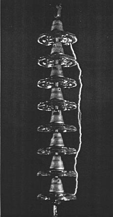
5 Short-circuit faults (Sw. kortslutningar) Also shunt fault A fault that is characterized by the flow of current between two or more phases or between phase(s) and earth (IEC definition) Examples Lightning Dirt/salt on insulators Flashover (Sw. överslag) line-line (wind) or line to tree Tower/pole or conductor falls Objects fall on conductors Cable insulation failure 5

6 Lightning most common Statistically 80 % of faults on overhead lines are due to lightning 6


7 Power lines and trees 400 kv 50 kv 400 kv lines unaffected by Gudrun 10 kv Distribution lines most affected 7
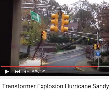
8 Effects of short-circuit current Arc (Sw. ljusbåge) Compare with welding Heating Fire and explosion (movie transformer blast) Vibration due to magnetic forces Parallel conductors are attracted (F=B i l) 8
9 Heating Resistive losses RI 2 heat energy = RI 2 dt = RI 2 t Temperature rises with stored heat energy (if no cooling) Same I 2 t gives equal heating Time=1/I 2 Safe = no time limit Overload I 2 t=constant Short-circuit fault Current 9
10 Symmetrical 3-phase short-circuit Z TH Z TH + I SC I F V TH VF=VTH + I SC =V TH /Z TH I F =V F /Z TH =V TH /Z TH Thévenin gives only I F and not the prefault load current Prefault voltage V F often assumed same at all buses 10
11 3-phase short-circuit: Currents I I I Prefault I F + + I F System System V F System = sources V F + at V F = + V F System sources at 0 + V F Current during fault I = I prefault + I F Prefault current often << I F and neglected 11
12 Network during fault Standard simplifications to find fault current Transformers: Only X eq, no phase shift Transmission lines: Only series reactance Generators: E g behind X d, no saliency, R a or saturation Large motors: Like generators Small motors: Neglected Non-rotating loads: Neglected 12
13 Series impedances limit S-C currents All transformer x to same base: 400/130 kv, x= MVA MVA base 130/20 kv, x= MVA MVA base x p.u. 20/0.4 kv, x= MVA MVA base 50 x 0.25 p.u. and x p.u. The last transformer dominates Z TH Z TH400 j0.013 j0.25 j12.5 V TH ~ 400 kv 130 kv 20 kv 0.4 kv
14 S-C currents at different voltage levels Try 0Ω fault at 0.4 kv. Assume ΣZ=20 p.u. I SC =0.05 p.u. I base400 =100MVA/( 3 400kV)=144 A A=7.2 A I base130 =100MVA/( 3 130kV)=444 A A= 22 A I base30 =100MVA/( 3 20kV)=2.9 ka ka= 145 A I base0.4 =100MVA/( 3 0.4kV)=144 ka ka= 7200 A Z TH400 j0.013 j0.25 j12.5 V TH ~ 400 kv 130 kv 20 kv 0.4 kv
15 Interrupting large currents Fuses (Sw. säkringar) Use the melting effect of the fault current (arc) Circuit breakers (Sw. effektbrytare) interrupt ka in ms Extinguish arc using pressurized air (arc energy), vacuum, oil etc. Circuit breaker operation Automatic by relay protection Manual remote control from control center 15
 Visible interruption Motorized or manual (rural MV) Interrupts < Load current OK: Youtube 110 kv disconnector closes and opens Too large")
16 Disconnector/Isolator not for short-circuits (Sw. frånskiljare) Visible interruption Motorized or manual (rural MV) Interrupts < Load current OK: Youtube 110 kv disconnector closes and opens Too large current: Youtube 138 kv Elkford Design challenge: Weather Sweden USA Open Closed Open Closed Source: Nicklasson 16


17 Circuit breaker Sweden USA Source:ABB Open Closed Interrupts large current Perhaps 63 ka in 20 ms Short-circuit current Hidden contacts Control Protection systems Manual remote Design challenge Speed and current 17


18 Disconnecting circuit breaker Combines breaker and disconnector More reliable and compact Disconnector Breaker Line Combined breaker Line Lindome 400 kv station, also in Lund 18
 uses SF6 gas Isolates much better than air - reduces size SF6 a greenhouse gas alternatives are sought")
19 More compact switchgear SF 6 Air Source: Lakervi Disconnecting circuit breaker in air insulated station Gas Insulated Switchgear (GIS) uses SF6 gas Isolates much better than air - reduces size SF6 a greenhouse gas alternatives are sought for 19
20 Protection for automatic fault clearing Need Detect fault Isolate faulted component Restore service for unfaulted components Aims Continued supply for rest of system Protect faulted part from damage (A fuse does this, but needs manual replacement) 20
21 Basic fault clearing system (Sw. felbortkopplingssystem) CT CB PT CB - Circuit Breaker CT - Current Transformer PT - Potential Transformer Relay Batteries for CB operation Possible communication The protection relay takes CB trip decision based on inputs Many relays can operate same breaker Initially relays were electro-mechanical, then electronic and now use a microprocessor/dsp and GPS 21
 Reduces current Typically 1000/2 A Current monitored Control center")
22 Current transformer (Sw. strömtransf.) Reduces current Typically 1000/2 A Current monitored Control center Protection equipment P, Q transducers Source:ABB 22
 Source:ABB Reduces voltage")

23 Voltage/potential transformer (Sw. spänningstransformator) Source:ABB Reduces voltage Typically x kv/110 V Voltage monitored Control center Protection equipment P, Q transducers Also C voltage divider 23

24 Capacitive Voltage Transformer 24
 Passive overvoltage protection Alternative to air gap Nonlinear resistance gives")
25 Surge arrester/lightning arrester (Sw. ventilavledare) Passive overvoltage protection Alternative to air gap Nonlinear resistance gives short-circuits at high voltages Sends lightning to ground Source: ABB 25
26 Layout Disconnector Current transformer Circuit breaker Disconnector Busbar Voltage transformer Surge arrester 26
27 Protection system tasks Detect fault Is there a fault? Short-circuit or only high load? I SC =5-7 p.u. of synchronous generators simplifies this! I SC of power electronic generators only about 1.2 p.u.! Isolate fault Open ( trip ) circuit breaker(s) (CB) Many alternatives Coordination required Which protection unit should react and open which CB? Isolate as small area as possible Isolation must happen also if one component fails 27
28 Different protection for different objects Differential protection where I in -I out >0 means fault Lines Transformers Busbars Generators Overcurrent protection I in I out I in I out I in I out1 I out2 Lines in radial (distribution) systems Overcurrent relay with directional sensitivity Lines in meshed (transmission) systems Generators 28
29 Current differential protection Compare i in and i out i in i out 0 no internal fault i in i out >>0 internal fault: Trip CB Applicable to generators, transformers, lines, busbars Generators i in and i out of each winding Communication needed for lines G M 29
30 Protection zones Defined for protected objects Dedicated protection for each zone Zone border where current is measured Zones overlap with CB in overlap zones Isolated at fault anywhere inside Perfect for differential protection G M 30
31 Time-delay overcurrent relay for line Detect overcurrent Wait delay time T Trip CB Time T Trip Constant delay characteristic 1 Relative overcurrent Multiple overcurrent relays can be co-ordinated Different delays decide tripping order Few fixed delay times practical, e.g. 0, 0,25, 1 s 31
32 Time-delay overcurrent relay for line Detect overcurrent Wait delay time T(I) Trip CB Time Trip Inverse 1/t characteristic 1 Relative overcurrent Fuses also have 1/t characteristic Easy to co-ordinate inverse time relays with fuses 32
33 Example: Co-ordination radial system I SC increases when approaching source R1 has higher current setting than R2 R1 CB1 Time R2 CB2 Load1 R1 R2 Load2 Relative overcurrent 33
34 Example: Fault in radial system R1 R2 CB1 CB2 Load2 L1» R1 and R2 detect overcurrent Delay of R2 smallest» R2 operates CB2 first Isolates fault + Load 2 No overcurrent R1 reset Fault clearing selective» If R2 or CB2 fails R1 not reset Time Extra delay of R1 before it operates CB1 Isolates fault + Load 2 but also Load 1 Fault clearing non-selective 34 R1 R2 Current
35 Fault in radial system: At home F2 F1 Me F3 Neighbor» Both F1 and F2 detect overcurrent» Delay of F2» Fuse F2 blows first Isolates fault and Me Selective fault clearing» If fuse F2 fails Extra delay of F1 F1 blows Time Isolates fault + Me but also Neighbor Non-selective fault clearing F1 F2 Current 35
36 Co-ordination (Sw. selektivplanering) Relays 1 and 2 coordinated in example: For the line, Relay 2 is primary protection and provides selective fault clearing (Sw: selektiv felbortkoppling) Relay 1 is backup protection and provides non-selective fault clearing (Sw: reservbortkoppling) Always true (regardless of I) since t(i) curves do not cross Rule: Longer delay close to source 36
37 Line fed from both ends G R1 R2 R3 R4 G Rule not applicable due to many sources Use directional relays:» R1 and R3 only trip for fault to their right» R2 and R4 only trip for fault to their left Direction is obtained from phase difference of V and I measured by relay 37
38 Impedance relay Let relay measure V/I=Z=R+jX Normally load makes Z > Z line (Think Thévenin!) Fault on line makes Z < Z line TRIP! X Trip Radius= Z line R 38
39 Impedance relay types Directional X Z line Admittance or MHO Trip limit a certain admittance X Trip Trip R R 39
40 Distance protection (Sw. distansskydd) Series impedance ~ distance along line Z <0.8 Z line equivalent to» Zero Ω fault within 80% of line length» The reach of the relay is 80% 40
41 Distance protection zones Zone 1 relay at A, Primary: 80%, no delay Zone 2 relay at A, Backup 1: 120%, delay Zone 3 relay at A, Backup 2: %, longer delay G Time A B C D Zone 3 Zone 2 Zone 1 G Distance 41
42 Distance protection coordination G A B C D Time Time Distance Distance Shown fault Primary protection from Zone 1 at C and D Backup protection from Zone 3 at A 42
43 Protection system performance High dependability Always isolate targeted fault High sensitivity good High security Only react to targeted faults High sensitivity bad Fast Good for (transient) stability Safety Compromise 43
44 When lights go out in radial system (Youtube blackout sandy jersey city) 1. A fault occurs. Voltages go low or zero. 2a. An upstream fuse/relay detects fault 2b. Fuse or breaker isolates downstream system. Voltage of unfaulted parts recover. 3. Fault is removed 4. Automatic reclosing after delay (successful if fault not permanent) or manual replacement of fuse Voltage of faulted parts recover. 44
45 Short-circuit transients Usually transients are steps and sinusoids are stationary AC power system (equivalent) R L i(t) E(t) = 2E sin(ωt +α) SW SW closes at t=0 Determine i(t) 45
46 R-L transients Math L di(t) + Ri(t) = 2E sin(ωt +α) with i(0) = 0 dt i(t) = i stationary (t) + i transient (t) = i AC (t) + i DC (t) i AC (t) = 2E sin(ωt +α θ) Z i DC (t) = 2E sin(α θ)e Z t T Z = R 2 + ( ωl) 2 ; θ = tan 1 ( ωl / R); T = L / R 46
47 R-L transients Power eng. Avoid α dependence Use worst case: α=(θ-π/2) Avoid instantaneous values i DC (t) = 2E Z t e T Use rms: I AC =E/Z Treat I DC as constant I RMS (t) = 2 I AC + [ I DC (t)] 2 2 = I AC where τ is time in cycles t /T + [ 2I AC e ] 2 2t = I AC 1+ 2e 2t /T T = 2 τ f R L = 4πτ X / R K(τ) 47
48 Exponential component Depends on initial condition Different α in the three phases Asymmetrical current Slow decay for high L/R (low losses) Increases peak current I RMS up to 3 I AC 48
49 Summary Compute short-circuit fault current with Circuit breaker is used for Disconnector is used for Fault clearing system includes protective relay with Sensors: Actuator: 3 protection types:,, Backup protection acts after delay if protection fails Deenergizing minimum area = fault clearing S-C current transient =
50 Summary Compute short-circuit fault current with Thévenin equivalent Circuit breaker is used for interrupting fault current Disconnector is used for interrupting load current or less Fault clearing system includes protective relay with Sensors: Current and voltage/potential transformers Actuator: Circuit breaker 3 protection types: differential, overcurrent, distance protection Backup protection acts after delay if primary protection fails Deenergizing minimum area = selective fault clearing S-C current transient = sinusoidal AC + expontial DC 50


51
Protection Basics Presented by John S. Levine, P.E. Levine Lectronics and Lectric, Inc GE Consumer & Industrial Multilin
 Protection Basics Presented by John S. Levine, P.E. Levine Lectronics and Lectric, Inc. 770 565-1556 John@L-3.com 1 Protection Fundamentals By John Levine 2 Introductions Tools Outline Enervista Launchpad
Numbering System for Protective Devices, Control and Indication Devices for Power Systems
 Appendix C Numbering System for Protective Devices, Control and Indication Devices for Power Systems C.1 APPLICATION OF PROTECTIVE RELAYS, CONTROL AND ALARM DEVICES FOR POWER SYSTEM CIRCUITS The requirements
RAIDK, RAIDG, RAPDK and RACIK Phase overcurrent and earth-fault protection assemblies based on single phase measuring elements
 RAIDK, RAIDG, RAPDK and RACIK Phase overcurrent and earth-fault protection assemblies based on single phase measuring elements User s Guide General Most faults in power systems can be detected by applying
Tab 2 Voltage Stresses Switching Transients
 Tab 2 Voltage Stresses Switching Transients Distribution System Engineering Course Unit 10 2017 Industry, Inc. All rights reserved. Transient Overvoltages Decay with time, usually within one or two cycles
Transformer Protection
 Transformer Protection Transformer Protection Outline Fuses Protection Example Overcurrent Protection Differential Relaying Current Matching Phase Shift Compensation Tap Changing Under Load Magnetizing
Electrical Protection System Design and Operation
 ELEC9713 Industrial and Commercial Power Systems Electrical Protection System Design and Operation 1. Function of Electrical Protection Systems The three primary aims of overcurrent electrical protection
IV/IV B.Tech (Regular) DEGREE EXAMINATION. Electrical &Electronics Engineering
 DEGREE EXAMINATION. Electrical &Electronics Engineering") Hall Ticket Number: 14EE704 November, 2017 Seventh Semester Time: Three Hours Answer Question No.1 compulsorily. Answer ONE question from each unit. IV/IV B.Tech (Regular) DEGREE EXAMINATION Electrical
Hall Ticket Number: 14EE704 November, 2017 Seventh Semester Time: Three Hours Answer Question No.1 compulsorily. Answer ONE question from each unit. IV/IV B.Tech (Regular) DEGREE EXAMINATION Electrical
3. (a) List out the advantages and disadvantages of HRC fuse (b) Explain fuse Characteristics in detail. [8+8]
![3. (a) List out the advantages and disadvantages of HRC fuse (b) Explain fuse Characteristics in detail. [8+8]](/thumbs/77/76027701.jpg "3. (a) List out the advantages and disadvantages of HRC fuse (b) Explain fuse Characteristics in detail. [8+8]") Code No: RR320205 Set No. 1 1. (a) Explain about Bewley s Lattice diagrams and also mention the uses of these diagrams. [6+2] (b) A line of surge impedance of 400 ohms is charged from a battery of constant
Code No: RR320205 Set No. 1 1. (a) Explain about Bewley s Lattice diagrams and also mention the uses of these diagrams. [6+2] (b) A line of surge impedance of 400 ohms is charged from a battery of constant
A short introduction to Protection and Automation Philosophy
 Training Center A short introduction to Protection and Automation Philosophy Philippe Goossens & Cédric Moors Training Center Contents Definitions and basic concepts Differential and distance protection
CONTENTS. 1. Introduction Generating Stations 9 40
 CONTENTS 1. Introduction 1 8 Importance of Electrical Energy Generation of Electrical Energy Sources of Energy Comparison of Energy Sources Units of Energy Relationship among Energy Units Efficiency Calorific
PROTECTION of electricity distribution networks
 PROTECTION of electricity distribution networks Juan M. Gers and Edward J. Holmes The Institution of Electrical Engineers Contents Preface and acknowledgments x 1 Introduction 1 1.1 Basic principles of
Course No: 1 13 (3 Days) FAULT CURRENT CALCULATION & RELAY SETTING & RELAY CO-ORDINATION. Course Content
 FAULT CURRENT CALCULATION & RELAY SETTING & RELAY CO-ORDINATION. Course Content") Course No: 1 13 (3 Days) FAULT CURRENT CALCULATION & RELAY SETTING & RELAY CO-ORDINATION Sr. No. Course Content 1.0 Fault Current Calculations 1.1 Introduction to per unit and percentage impedance 1.2
Course No: 1 13 (3 Days) FAULT CURRENT CALCULATION & RELAY SETTING & RELAY CO-ORDINATION Sr. No. Course Content 1.0 Fault Current Calculations 1.1 Introduction to per unit and percentage impedance 1.2
COPYRIGHTED MATERIAL. Index
 Index Note: Bold italic type refers to entries in the Table of Contents, refers to a Standard Title and Reference number and # refers to a specific standard within the buff book 91, 40, 48* 100, 8, 22*,
Protection of Electrical Networks. Christophe Prévé
 Protection of Electrical Networks Christophe Prévé This Page Intentionally Left Blank Protection of Electrical Networks This Page Intentionally Left Blank Protection of Electrical Networks Christophe Prévé
Modelling of Sf6 Circuit Breaker Arc Quenching Phenomena In Pscad
 Day 2 - Session IV-A High Voltage 163 Modelling of Sf6 Circuit Breaker Arc Quenching Phenomena In Pscad B. Kondala Rao, Gopal Gajjar ABB Ltd., Maneja, Vadodara, India Introduction Circuit breakers play
ELECTRICAL POWER ENGINEERING
 Introduction This trainer has been designed to provide students with a fully comprehensive knowledge in Electrical Power Engineering systems. The trainer is composed of a set of modules for the simulation
R10. IV B.Tech I Semester Regular/Supplementary Examinations, Nov/Dec SWITCH GEAR AND PROTECTION. (Electrical and Electronics Engineering)
") R10 Set No. 1 Code No: R41023 1. a) Explain how arc is initiated and sustained in a circuit breaker when the CB controls separates. b) The following data refers to a 3-phase, 50 Hz generator: emf between
R10 Set No. 1 Code No: R41023 1. a) Explain how arc is initiated and sustained in a circuit breaker when the CB controls separates. b) The following data refers to a 3-phase, 50 Hz generator: emf between
PROTECTION APPLICATION HANDBOOK
 BOOK No 6 Revision 0 Global Organization Innovative Solutions Product & Substation System Business Business PROTECTION APPLICATION HANDBOOK BA THS / BU Transmission Systems and Substations LEC Support
HIGH VOLTAGE CIRCUIT BREAKERS
 HIGH VOLTAGE CIRCUIT BREAKERS Design and Applications Second Edition, Revised and Expanded RUBEN D. GARZON Square D Co. Smyrna, Tennessee MARCEL Ш D E К К E R MARCEL DEKKER, INC. NEW YORK BASEL CONTENTS
EE 1402 HIGH VOLTAGE ENGINEERING
 EE 1402 HIGH VOLTAGE ENGINEERING Unit 5 TESTS OF INSULATORS Type Test To Check The Design Features Routine Test To Check The Quality Of The Individual Test Piece. High Voltage Tests Include (i) Power frequency
Topic 6 Quiz, February 2017 Impedance and Fault Current Calculations For Radial Systems TLC ONLY!!!!! DUE DATE FOR TLC- February 14, 2017
 Topic 6 Quiz, February 2017 Impedance and Fault Current Calculations For Radial Systems TLC ONLY!!!!! DUE DATE FOR TLC- February 14, 2017 NAME: LOCATION: 1. The primitive self-inductance per foot of length
BE Semester- VI (Electrical Engineering) Question Bank (E 605 ELECTRICAL POWER SYSTEM - II) Y - Y transformer : 300 MVA, 33Y / 220Y kv, X = 15 %
 Question Bank (E 605 ELECTRICAL POWER SYSTEM - II) Y - Y transformer : 300 MVA, 33Y / 220Y kv, X = 15 %") BE Semester- V (Electrical Engineering) Question Bank (E 605 ELECTRCAL POWER SYSTEM - ) All questions carry equal marks (10 marks) Q.1 Explain per unit system in context with three-phase power system and
BE Semester- V (Electrical Engineering) Question Bank (E 605 ELECTRCAL POWER SYSTEM - ) All questions carry equal marks (10 marks) Q.1 Explain per unit system in context with three-phase power system and
A Guide to the DC Decay of Fault Current and X/R Ratios
 A Guide to the DC Decay of Fault Current and X/R Ratios Introduction This guide presents a guide to the theory of DC decay of fault currents and X/R ratios and the calculation of these values in Ipsa.
SHORT CIRCUIT ANALYSIS OF 220/132 KV SUBSTATION BY USING ETAP
 SHORT CIRCUIT ANALYSIS OF 220/132 KV SUBSTATION BY USING ETAP Kiran V. Natkar 1, Naveen Kumar 2 1 Student, M.E., Electrical Power System, MSS CET/ Dr. B.A.M. University, (India) 2 Electrical Power System,
ARC FLASH HAZARD ANALYSIS AND MITIGATION
 ARC FLASH HAZARD ANALYSIS AND MITIGATION J.C. Das IEEE PRESS SERIES 0N POWER ENGINEERING Mohamed E. El-Hawary, Series Editor IEEE IEEE PRESS WILEY A JOHN WILEY & SONS, INC., PUBLICATION CONTENTS Foreword
How to maximize reliability using an alternative distribution system for critical loads
 White Paper WP024001EN How to maximize reliability using an alternative distribution system for critical loads Executive summary The electric power industry has several different distribution topologies
PJM Manual 07:: PJM Protection Standards Revision: 2 Effective Date: July 1, 2016
 PJM Manual 07:: PJM Protection Standards Revision: 2 Effective Date: July 1, 2016 Prepared by System Planning Division Transmission Planning Department PJM 2016 Table of Contents Table of Contents Approval...6
High voltage engineering
 High voltage engineering Overvoltages power frequency switching surges lightning surges Overvoltage protection earth wires spark gaps surge arresters Insulation coordination Overvoltages power frequency
Single Line Diagram of Substations
 Single Line Diagram of Substations Substations Electric power is produced at the power generating stations, which are generally located far away from the load centers. High voltage transmission lines are
MV network design & devices selection EXERCISE BOOK
 MV network design & devices selection EXERCISE BOOK EXERCISES 01 - MV substation architectures 02 - MV substation architectures 03 - Industrial C13-200 MV substation 04 - Max. distance between surge arrester
Introduce system protection relays like underfrequency relays, rate of change of frequency relays, reverse - power flow
 Module 1 : Fundamentals of Power System Protection Lecture 3 : Protection Paradigms - System Protection Objectives In this lecture we will: Overview dynamics in power systems. Introduce system protection
Electricity Ten Year Statement November Electricity Ten Year Statement November Appendix D
 Electricity Ten Year Statement November 2017 01 Electricity Ten Year Statement November 2017 001 Appendix D 1 Short-circuit currents 02 2 Short-circuit current terminology 04 3 Data requirements 07 4 Fault
CHAPTER 2 ELECTRICAL POWER SYSTEM OVERCURRENTS
 CHAPTER 2 ELECTRICAL POWER SYSTEM OVERCURRENTS 2-1. General but less than locked-rotor amperes and flows only Electrical power systems must be designed to serve in the normal circuit path. a variety of
Medium voltage circuit breaker technical guide
 IEC 56-1987 - ANSI C37-06 1987 COMPARISON CONTENTS page 1 - Rated voltage 3 2 - Rated isolating level 3 3 - Rated voltage during normal running 4 4 - Allowable short time current 4 5 - Allowable current
Level 6 Graduate Diploma in Engineering Electrical Energy Systems
 9210-114 Level 6 Graduate Diploma in Engineering Electrical Energy Systems Sample Paper You should have the following for this examination one answer book non-programmable calculator pen, pencil, ruler,
COPYRIGHTED MATERIAL. Introduction to protective relaying. 1.1 What is relaying?
 1 Introduction to protective relaying 1.1 What is relaying? In order to understand the function of protective relaying systems, one must be familiar with the nature and the modes of operation of an electric
UPGRADING SUBSTATION RELAYS TO DIGITAL RECLOSERS AND THEIR COORDINATION WITH SECTIONALIZERS
 UPGRADING SUBSTATION RELAYS TO DIGITAL RECLOSERS AND THEIR COORDINATION WITH SECTIONALIZERS 1 B. RAMESH, 2 K. P. VITTAL Student Member, IEEE, EEE Department, National Institute of Technology Karnataka,
A Simple Simulation Model for Analyzing Very Fast Transient Overvoltage in Gas Insulated Switchgear
 A Simple Simulation Model for Analyzing Very Fast Transient Overvoltage in Gas Insulated Switchgear Nguyen Nhat Nam Abstract The paper presents an simple model based on ATP-EMTP software to analyze very
Voltage Sag Mitigation by Neutral Grounding Resistance Application in Distribution System of Provincial Electricity Authority
 Voltage Sag Mitigation by Neutral Grounding Resistance Application in Distribution System of Provincial Electricity Authority S. Songsiri * and S. Sirisumrannukul Abstract This paper presents an application
Earth Fault Protection
 Earth Fault Protection Course No: E03-038 Credit: 3 PDH Velimir Lackovic, Char. Eng. Continuing Education and Development, Inc. 9 Greyridge Farm Court Stony Point, NY 10980 P: (877) 322-5800 F: (877) 322-4774
G. KOEPPL Koeppl Power Experts Switzerland
 PS3: Substation Design: New Solutions and Experiences Bus-Node Substation A Big Improvement in Short-Circuit and Switching Properties at Reduced Substation Costs G. KOEPPL Koeppl Power Experts Switzerland
Electrical Power Systems
 Electrical Power Systems CONCEPT, THEORY AND PRACTICE SECOND EDITION SUBIR RAY Professor MVJ College of Engineering Bangalore PHI Learning Pfcte tofm Delhi-110092 2014 Preface xv Preface to the First Edition
In Class Examples (ICE)
") In Class Examples (ICE) 1 1. A 3φ 765kV, 60Hz, 300km, completely transposed line has the following positive-sequence impedance and admittance: z = 0.0165 + j0.3306 = 0.3310 87.14 o Ω/km y = j4.67 410-6
In Class Examples (ICE) 1 1. A 3φ 765kV, 60Hz, 300km, completely transposed line has the following positive-sequence impedance and admittance: z = 0.0165 + j0.3306 = 0.3310 87.14 o Ω/km y = j4.67 410-6
SCHEME OF COURSE WORK ( ) Electrical & Electronics Engineering. Electrical machines-i, II and power transmission engineering
 Electrical & Electronics Engineering. Electrical machines-i, II and power transmission engineering") SCHEME OF COURSE WORK (2015-2016) COURSE DETAILS: Course Title Course Code Program Branch Semester Prerequisites Course to which it is prerequisite Switchgear and Protection 15EE1116 B.Tech Electrical
SCHEME OF COURSE WORK (2015-2016) COURSE DETAILS: Course Title Course Code Program Branch Semester Prerequisites Course to which it is prerequisite Switchgear and Protection 15EE1116 B.Tech Electrical
ANALYSIS OF VOLTAGE TRANSIENTS IN A MEDIUM VOLTAGE SYSTEM
 ANALYSIS OF VOLTAGE TRANSIENTS IN A MEDIUM VOLTAGE SYSTEM Anna Tjäder Chalmers University of Technology anna.tjader@chalmers.se Math Bollen Luleå University of Technology math.bollen@stri.se ABSTRACT Power
Alberta Interconnected Electric System Protection Standard
 Alberta Interconnected Electric System Protection Standard Revision 0 December 1, 2004 APEGGA Permit to Practice P-08200 Table of Contents Signature Page... 2 Table of Contents... 3 1.0 STAKEHOLDER REVIEW
Unit 2. Single Line Diagram of Substations
 Unit 2 Single Line Diagram of Substations Substations Electric power is produced at the power generating stations, which are generally located far away from the load centers. High voltage transmission
10. DISTURBANCE VOLTAGE WITHSTAND CAPABILITY
 9. INTRODUCTION Control Cabling The protection and control equipment in power plants and substations is influenced by various of environmental conditions. One of the most significant environmental factor
Sequence Networks p. 26 Sequence Network Connections and Voltages p. 27 Network Connections for Fault and General Unbalances p. 28 Sequence Network
 Preface p. iii Introduction and General Philosophies p. 1 Introduction p. 1 Classification of Relays p. 1 Analog/Digital/Numerical p. 2 Protective Relaying Systems and Their Design p. 2 Design Criteria
GIS Disconnector Switching Operation VFTO Study
 GIS Disconnector Switching Operation VFTO Study Mariusz Stosur, Marcin Szewczyk, Wojciech Piasecki, Marek Florkowski, Marek Fulczyk ABB Corporate Research Center in Krakow Starowislna 13A, 31-038 Krakow,
Appendix D Fault Levels
 Appendix D Fault Levels Page 1 Electricity Ten Year Statement November 2013 D.1 Short Circuit Currents Short Circuit Currents Three phase to earth and single phase to earth short circuit current analyses
EH2741 Communication and Control in Electric Power Systems Lecture 2
 KTH ROYAL INSTITUTE OF TECHNOLOGY EH2741 Communication and Control in Electric Power Systems Lecture 2 Lars Nordström larsno@kth.se Course map Outline Transmission Grids vs Distribution grids Primary Equipment
Adaptive Autoreclosure to Increase System Stability and Reduce Stress to Circuit Breakers
 Adaptive Autoreclosure to Increase System Stability and Reduce Stress to Circuit Breakers 70 th Annual Conference for Protective Relay Engineers Siemens AG 2017 All rights reserved. siemens.com/energy-management
A Study on Ferroresonance Mitigation Techniques for Power Transformer
 A Study on Ferroresonance Mitigation Techniques for Power Transformer S. I. Kim, B. C. Sung, S. N. Kim, Y. C. Choi, H. J. Kim Abstract--This paper presents a comprehensive study on the ferroresonance mitigation
Index. b back-flashover 245 biomass 207 breakers 74 buchholz protection 235 busbar sectionalizer 193 business enterprises 18
 331 Index a activity plan 318 agricultural enterprise 21 annual increase factor 12 annuity factor 44, 156 annuity method 38 ANSI code numbers 237 arrester, protection level 245 assessment of losses 38
TABLE OF CONTENT
 Page : 1 of 34 Project Engineering Standard www.klmtechgroup.com KLM Technology #03-12 Block Aronia, Jalan Sri Perkasa 2 Taman Tampoi Utama 81200 Johor Bahru Malaysia TABLE OF CONTENT SCOPE 3 REFERENCES
NOVEL PROTECTION SYSTEMS FOR ARC FURNACE TRANSFORMERS
 NOVEL PROTECTION SYSTEMS FOR ARC FURNACE TRANSFORMERS Ljubomir KOJOVIC Cooper Power Systems - U.S.A. Lkojovic@cooperpower.com INTRODUCTION In steel facilities that use Electric Arc Furnaces (EAFs) to manufacture
Cahier technique no. 193
 Collection Technique... Cahier technique no. 193 MV breaking techniques S. Théoleyre "Cahiers Techniques" is a collection of documents intended for engineers and technicians, people in the industry who
Busbars and lines are important elements
 CHAPTER CHAPTER 23 Protection of Busbars and Lines 23.1 Busbar Protection 23.2 Protection of Lines 23.3 Time-Graded Overcurrent Protection 23.4 Differential Pilot-Wire Protection 23.5 Distance Protection
2. Current interruption transients
 1 2. Current interruption transients For circuit breakers or other switching facilities, transient voltages just after the current interruptions are of great concern with successful current breakings,
ANALYSIS OF A FLASHOVER OPERATION ON TWO 138KV TRANSMISSION LINES
 ANALYSIS OF A FLASHOVER OPERATION ON TWO 138KV TRANSMISSION LINES Authors: Joe Perez, P.E.: SynchroGrid, College Station, Texas Hung Ming Chou, SynchroGrid, College Station, Texas Mike McMillan, Bryan
Bus Protection Fundamentals
 Bus Protection Fundamentals Terrence Smith GE Grid Solutions 2017 Texas A&M Protective Relay Conference Bus Protection Requirements High bus fault currents due to large number of circuits connected: CT
Fixed Series Compensation
 Fixed Series Compensation High-reliable turnkey services for fixed series compensation NR Electric Corporation The Fixed Series Compensation (FSC) solution is composed of NR's PCS-9570 FSC control and
Improved Arc Interruption of High Voltage SF 6 Circuit Breakers Using Modified Mayr s Differential Equation
 International Journal of Systems Science and Applied Mathematics 2017; 2(1): 25-29 http://www.sciencepublishinggroup.com/j/ijssam doi: 10.11648/j.ijssam.20170201.13 Improved Arc Interruption of High Voltage
NERC Protection Coordination Webinar Series June 9, Phil Tatro Jon Gardell
 Power Plant and Transmission System Protection Coordination GSU Phase Overcurrent (51T), GSU Ground Overcurrent (51TG), and Breaker Failure (50BF) Protection NERC Protection Coordination Webinar Series
EH27401 Communication and Control in Electric Power Systems Lecture 2. Lars Nordström
 EH27401 Communication and Control in Electric Power Systems Lecture 2 Lars Nordström larsn@ics.kth.se 1 Course map 2 Outline 1. Power System Topologies Transmission Grids vs Distribution grids Radial grids
Substation Preventive Maintenance
 Substation Preventive Maintenance PROVINCIAL ELECTRICITY AUTHORITY 1 Presentation Contents 1) A kind of substation 2) Electrical equipment details of AIS substation 3) Electrical equipment details of GIS
PIPSPC. Prepared by Eng: Ahmed Safie Eldin. And. Introduction. Protection Control. Practical. System. Power
 PIPSPC Practical Introduction Power System Protection Control Practical Introduction To Power System Protection And Control Prepared by Eng: Ahmed Safie Eldin 2005 Contents POWER SYSTEMS PRINCIPALS. 1
No. SSIEC-SEW SHINSUNG. Solid Insulation Eco Load Break Switch (SILO) SILO SERIES 15kV, 27kV 400A, 630A
 SILO SERIES 15kV, 27kV 400A, 630A") SHINSUNG Solid Insulation Eco Load Break Switch (SILO) SILO SERIES 15kV, 27kV 400A, 630A Enhanced Self Healing System General SILO is 3 phase, solid insulated load break switch (LBS) and vacuum interruption
SHINSUNG Solid Insulation Eco Load Break Switch (SILO) SILO SERIES 15kV, 27kV 400A, 630A Enhanced Self Healing System General SILO is 3 phase, solid insulated load break switch (LBS) and vacuum interruption
Course ELEC Introduction to electric power and energy systems. Additional exercises with answers December reactive power compensation
 Course ELEC0014 - Introduction to electric power and energy systems Additional exercises with answers December 2017 Exercise A1 Consider the system represented in the figure below. The four transmission
Specialists in HV and MV test and diagnostics. Testing in Substations
 Specialists in HV and MV test and diagnostics Testing in Substations Testing in Substations Testing in Substations At 4fores we specialize in the diagnosis and measurement of all types of existing technologies
ANALYSIS OF FAULTS INTERRUPTED BY GENERATOR
 ANALYSIS OF FAULTS INTERRUPTED BY GENERATOR CIRCUIT BREAKER SF 6 ING. VÁCLAV JEŽEK PROF. ING. ZDENĚK VOSTRACKÝ, DRSC., DR.H.C. Abstract: This article describes the analysis of faults interrupted by generator
ABSTRACT 1 INTRODUCTION
 ELECTROMAGNETIC ANALYSIS OF WIND TURBINE GROUNDING SYSTEMS Maria Lorentzou*, Ian Cotton**, Nikos Hatziargyriou*, Nick Jenkins** * National Technical University of Athens, 42 Patission Street, 1682 Athens,
MV, HV AND EHV SWITCHGEAR TESTING & COMMISSIONING
 Training Title MV, HV AND EHV SWITCHGEAR TESTING & COMMISSIONING Training Duration 5 days Training Date MV, HV and EHV Switchgear Testing & Commissioning 5 21 25 Sep $3,750 Dubai, UAE In any of the 5 star
Device circuit breakers Selective power distribution: branch out, individual adaptation, modular extension
 Power & Signal Quality TRABTECH Device circuit breakers Selective power distribution: branch out, individual adaptation, modular extension Interference-free mains supply and signal transmission A constant
LV/MV/HV CIRCUIT BREAKERS (SWITCH GEAR) DESIGN, INSPECTION, MAINTENANCE, REPAIR & TROUBLESHOOTING
 DESIGN, INSPECTION, MAINTENANCE, REPAIR & TROUBLESHOOTING") Training Title LV/MV/HV CIRCUIT BREAKERS (SWITCH GEAR) DESIGN, INSPECTION, MAINTENANCE, REPAIR & TROUBLESHOOTING Training Duration 5 days Training Venue and Dates LV/MV/HV Circuit Breakers (Switchgear):
Training Title LV/MV/HV CIRCUIT BREAKERS (SWITCH GEAR) DESIGN, INSPECTION, MAINTENANCE, REPAIR & TROUBLESHOOTING Training Duration 5 days Training Venue and Dates LV/MV/HV Circuit Breakers (Switchgear):
Unit 3 Magnetism...21 Introduction The Natural Magnet Magnetic Polarities Magnetic Compass...21
 Chapter 1 Electrical Fundamentals Unit 1 Matter...3 Introduction...3 1.1 Matter...3 1.2 Atomic Theory...3 1.3 Law of Electrical Charges...4 1.4 Law of Atomic Charges...4 Negative Atomic Charge...4 Positive
NERC Protection Coordination Webinar Series June 16, Phil Tatro Jon Gardell
 Power Plant and Transmission System Protection Coordination Phase Distance (21) and Voltage-Controlled or Voltage-Restrained Overcurrent Protection (51V) NERC Protection Coordination Webinar Series June
MV/LV transformer substations: theory and examples of short-circuit calculation
 2 September 2005 1SDC007101G0201 Technical Application Papers MV/LV transformer substations: theory and examples of short-circuit calculation Technical Application Papers MV/LV transformer substations:
Modern transformer relays include a comprehensive set of protective elements to protect transformers from faults and abnormal operating conditions
 1 Transmission transformers are important links in the bulk power system. They allow transfer of power from generation centers, up to the high-voltage grid, and to bulk electric substations for distribution
Preface...x Chapter 1 Electrical Fundamentals
 Preface...x Chapter 1 Electrical Fundamentals Unit 1 Matter...3 Introduction...3 1.1 Matter...3 1.2 Atomic Theory...3 1.3 Law of Electrical Charges...4 1.4 Law of Atomic Charges...5 Negative Atomic Charge...5
SAFETY ASPECTS AND NOVEL TECHNICAL SOLUTIONS FOR EARTH FAULT MANAGEMENT IN MV ELECTRICITY DISTRIBUTION NETWORKS
 SAFETY ASPECTS AND NOVEL TECHNICAL SOLUTIONS FOR EARTH FAULT MANAGEMENT IN MV ELECTRICITY DISTRIBUTION NETWORKS A. Nikander*, P. Järventausta* *Tampere University of Technology, Finland, ari.nikander@tut.fi,
# - - Internal * On Line Examination
 COURSE NAME : ELECTRICAL ENGINEERING GROUP COURSE CODE : EE/EP SEMESTER : FIFTH SUBJECT TITLE : SWITCHGEAR and PROTECTION SUBJECT CODE : Teaching and Examination Scheme: Teaching Scheme TH TU PR PAPER
Industrial Electrician Level 3
 Industrial Electrician Level 3 Industrial Electrician Unit: C1 Industrial Electrical Code I Level: Three Duration: 77 hours Theory: Practical: 77 hours 0 hours Overview: This unit is designed to provide
Transformer protection IED RET 670
 Gunnar Stranne Transformer protection IED RET 670 Santiago Septiembre 5, 2006 1 Transformer protection IED RET670 2 Introduction features and applications Differential protection functions Restricted Earth
TEE 601: SWITCHGEAR AND PROTECTION
 TEE 601: SWITCHGEAR AND PROTECTION UNIT I PROTECTIVE RELAYS Basic principles, types, Construction and characteristics of electromagnetic relays, Elements of static relays, Comparators, Basic principle
Electrical Engineering. Power Systems. Comprehensive Theory with Solved Examples and Practice Questions. Publications
 Electrical Engineering Power Systems Comprehensive Theory with Solved Examples and Practice Questions Publications Publications MADE EASY Publications Corporate Office: 44-A/4, Kalu Sarai (Near Hauz Khas
HIGH VOLTAGE ENGINEERING(FEEE6402) LECTURER-24
 LECTURER-24") LECTURER-24 GENERATION OF HIGH ALTERNATING VOLTAGES When test voltage requirements are less than about 300kV, a single transformer can be used for test purposes. The impedance of the transformer should
LECTURER-24 GENERATION OF HIGH ALTERNATING VOLTAGES When test voltage requirements are less than about 300kV, a single transformer can be used for test purposes. The impedance of the transformer should
VI 3 - i TABLE OF CONTENTS
 VI 3 - i TABLE OF CONTENTS 3 PROJECT SPECIFIC DATA... 1 3.1 DEFINITIONS... 1 3.1.1 Design Data, High and Medium Voltage... 1 3.1.2 Design Data, Low Voltage Equipment... 2 3.1.3 Phase Relationship... 3
Calculation of Transient Overvoltages by using EMTP software in a 2-Phase 132KV GIS
 Calculation of Transient Overvoltages by using EMTP software in a 2-Phase 132KV GIS M. Kondalu, Dr. P.S. Subramanyam Electrical & Electronics Engineering, JNT University. Hyderabad. Joginpally B.R. Engineering
2015 Relay School Bus Protection Mike Kockott March, 2015
 2015 Relay School Bus Protection Mike Kockott March, 2015 History of Bus Protection Circulating current differential (1900s) High impedance differential (1940s) Percentage restrained differential (1960s)
SUBJECT CODE : EE6702 SUBJECT NAME: Protection & switchgear STAFF NAME : Ms.J.C.Vinitha
 SUBJECT CODE : EE6702 SUBJECT NAME: Protection & switchgear STAFF NAME : Ms.J.C.Vinitha EE2402 - PROTECTION & SWITCHGEAR SYLLABUS ELECTRIC POWER SYSTEM Electricity is generated at a power plant (1), voltage
Analysis of Temporary Over-Voltages from Self-Excited Large Induction Motors in the Presence of Resonance - Case Studies
 Analysis of Temporary Over-Voltages from Self-Excited Large Induction Motors in the Presence of Resonance - Case Studies T.G. Martinich, M. Nagpal, A. Bimbhra Abstract-- Technological advancements in high-power
1% Switchgear and Substations
 1% Switchgear and Substations Switchgear and substations are not always matters of concern for transmitter designers, -because they are often part of the facilities of a typical installation. However,
In order to minimise distribution (11 and 22 kv) feeder breaker
 feeder breaker") Lightning protection for equipment on MV feeders By WJD van Schalkwyk and M du Preez, Eskom This article presents the influence of lightning on MV feeders supplying small power users (400/230 V) with focus
Lightning protection for equipment on MV feeders By WJD van Schalkwyk and M du Preez, Eskom This article presents the influence of lightning on MV feeders supplying small power users (400/230 V) with focus
A Pyrotechnic Fault Current Limiter Model for Transient Calculations in Industrial Power Systems
 A Pyrotechnic Fault Current Limiter Model for Transient Calculations in Industrial Power Systems T. C. Dias, B. D. Bonatto, J. M. C. Filho Abstract-- Isolated industrial power systems or with high selfgeneration,
EE030: Circuit Breaker & Switchgears Inspection, Maintenance, Design, Repair & Troubleshooting
 EE030: Circuit Breaker & Switchgears Inspection, Maintenance, Design, Repair & Troubleshooting EE030 Rev.001 CMCT COURSE OUTLINE Page 1 of 6 Training Description: This course is designed to update participants
Notes 1: Introduction to Distribution Systems
 Notes 1: Introduction to Distribution Systems 1.0 Introduction Power systems are comprised of 3 basic electrical subsystems. Generation subsystem Transmission subsystem Distribution subsystem The subtransmission
EE 741. Primary & Secondary Distribution Systems
 EE 741 Primary & Secondary Distribution Systems Radial-Type Primary Feeder Most common, simplest and lowest cost Example of Overhead Primary Feeder Layout Example of Underground Primary Feeder Layout Radial-Type
Distribution Feeder Principles
 Distribution Feeder Principles Distribution Feeder Principles Introduction Electrical distribution is the final stage in the delivery of electricity to end users. The distribution system s network carries