Welcome to 6.S084! Computation Structures (special)
|
|
|
- Alexina Robertson
- 6 years ago
- Views:
Transcription


1 Welcome to 6.S084! Computation Structures (special) Spring 2018


2 6.S084 Course Staff Instructors Arvind Daniel Sanchez Teaching Assistants Silvina Hanono Wachman Thomas Bourgeat Kathy Camenzind Josh Noel Brian Wheatman Andy Wright Guowei Zhang February 6, 2018 L01-2

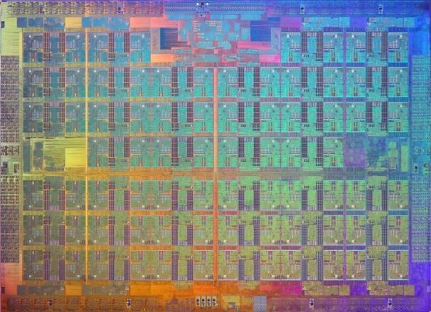
3 Computing Devices Then ENIAC, tons, 200KW, ~1000 ops/sec February 6, 2018 L01-3
4 Computing Devices Now Typical 2018 laptop 1kg, 10W, 10 billion ops/s February 6, 2018 L01-4


5 Computing Devices Now Typical 2018 laptop 1kg, 10W, 10 billion ops/s February 6, 2018 L01-4
6 An Introduction to the Digital World Application software Operating systems Virtual memory Interpretation & compilation Data and control structures Programmable architectures Combinational & sequential logic Devices Materials Atoms Virtual machines Programming languages Instruction set + memory Bits, Logic gates February 6, 2018 L01-5
7 An Introduction to the Digital World Application software Operating systems Virtual memory Interpretation & compilation Data and control structures Programmable architectures Combinational & sequential logic Devices Materials Atoms Virtual machines Programming languages Instruction set + memory Bits, Logic gates February 6, 2018 L01-5
8 The Power of Engineering Abstractions Good abstractions let us reason about behavior while shielding us from the details of the implementation. Virtual machines Programming languages Instruction set + memory Bits, Logic gates February 6, 2018 L01-6
9 The Power of Engineering Abstractions Good abstractions let us reason about behavior while shielding us from the details of the implementation. Corollary: implementation technologies can evolve while preserving the engineering investment at higher levels. Virtual machines Programming languages Instruction set + memory Bits, Logic gates February 6, 2018 L01-6
10 The Power of Engineering Abstractions Good abstractions let us reason about behavior while shielding us from the details of the implementation. Corollary: implementation technologies can evolve while preserving the engineering investment at higher levels. Leads to hierarchical design: Limited complexity at each level shorten design time, easier to verify Reusable building blocks Virtual machines Programming languages Instruction set + memory Bits, Logic gates February 6, 2018 L01-6
11 Our Focus: Programmable General-Purpose Processors February 6, 2018 L01-7
12 Our Focus: Programmable General-Purpose Processors Microprocessors are the basic building block of computer systems Understanding them is crucial even if you do not plan to work as a hardware designer February 6, 2018 L01-7
13 Our Focus: Programmable General-Purpose Processors Microprocessors are the basic building block of computer systems Understanding them is crucial even if you do not plan to work as a hardware designer Microprocessors are the most sophisticated digital systems that exist today Understanding them will help you design all kinds of hardware February 6, 2018 L01-7
14 Our Focus: Programmable General-Purpose Processors Microprocessors are the basic building block of computer systems Understanding them is crucial even if you do not plan to work as a hardware designer Microprocessors are the most sophisticated digital systems that exist today Understanding them will help you design all kinds of hardware We will use a new methodology that emphasizes learning-by-doing Building systems is the best way to understand them February 6, 2018 L01-7
15 Our Focus: Programmable General-Purpose Processors Microprocessors are the basic building block of computer systems Understanding them is crucial even if you do not plan to work as a hardware designer Microprocessors are the most sophisticated digital systems that exist today Understanding them will help you design all kinds of hardware We will use a new methodology that emphasizes learning-by-doing Building systems is the best way to understand them By the end of the term you would have designed a small multicore from scratch! February 6, 2018 L01-7
16 We Rely on Modern Design Tools Bluespec SystemVerilog Design Flow BSV source Bluespec Compiler Verilog RTL Bluespec Simulator Cycle Accurate Vivado Simulator Vivado Synthesis Design Compiler VCD output Power Analysis Designs are always expressed in a highlevel textual notation, i.e., programming language, which is compiled to generate circuit descriptions Gates ASIC February 6, 2018 L01-8

17 We Rely on Modern Design Tools Bluespec SystemVerilog Design Flow BSV source Bluespec Compiler Verilog RTL Bluespec Simulator Cycle Accurate Vivado Simulator Vivado Synthesis Design Compiler VCD output Power Analysis Designs are always expressed in a highlevel textual notation, i.e., programming language, which is compiled to generate circuit descriptions Gates ASIC February 6, 2018 L01-8
18 We Rely on Modern Design Tools Bluespec SystemVerilog Design Flow BSV source Bluespec Compiler Verilog RTL Bluespec Simulator Cycle Accurate Vivado Simulator Vivado Synthesis Design Compiler VCD output Power Analysis Designs are always expressed in a highlevel textual notation, i.e., programming language, which is compiled to generate circuit descriptions Gates ASIC February 6, 2018 L01-8
19 Key Differences with Learning-by-doing methodology using modern tools Modern tools let us go further Labs cover everything we teach Software-based methodology helps develop programming skills February 6, 2018 L01-9
20 Key Differences with Learning-by-doing methodology using modern tools Modern tools let us go further Labs cover everything we teach Software-based methodology helps develop programming skills More emphasis on labs and project than on quizzes February 6, 2018 L01-9
21 Key Differences with Learning-by-doing methodology using modern tools Modern tools let us go further Labs cover everything we teach Software-based methodology helps develop programming skills More emphasis on labs and project than on quizzes More focus on processor organization February 6, 2018 L01-9
22 Key Differences with Learning-by-doing methodology using modern tools Modern tools let us go further Labs cover everything we teach Software-based methodology helps develop programming skills More emphasis on labs and project than on quizzes More focus on processor organization Will not cover low-level (analog) circuit design February 6, 2018 L01-9
23 Key Differences with Learning-by-doing methodology using modern tools Modern tools let us go further Labs cover everything we teach Software-based methodology helps develop programming skills More emphasis on labs and project than on quizzes More focus on processor organization Will not cover low-level (analog) circuit design We assume you already have basic programming skills, at the level of or equivalent Contact us if you are not sure you meet this February 6, 2018 L01-9
24 Course Mechanics Three modules: Digital design: Combinational and sequential circuits (L1-7) Computer organization: Instruction sets, simple processor design, caches, virtual memory, and operating systems (L8-14) High-performance processors: pipelining and parallelism (L15-24) February 6, 2018 L01-10
25 Course Mechanics Three modules: Digital design: Combinational and sequential circuits (L1-7) Computer organization: Instruction sets, simple processor design, caches, virtual memory, and operating systems (L8-14) High-performance processors: pipelining and parallelism (L15-24) 2 lectures/week (Arvind + Daniel): handouts on website February 6, 2018 L01-10
26 Course Mechanics Three modules: Digital design: Combinational and sequential circuits (L1-7) Computer organization: Instruction sets, simple processor design, caches, virtual memory, and operating systems (L8-14) High-performance processors: pipelining and parallelism (L15-24) 2 lectures/week (Arvind + Daniel): handouts on website 2 recitations/week (Silvina + Andy): work through tutorial problems using skills and concepts from previous lecture February 6, 2018 L01-10
27 Course Mechanics Three modules: Digital design: Combinational and sequential circuits (L1-7) Computer organization: Instruction sets, simple processor design, caches, virtual memory, and operating systems (L8-14) High-performance processors: pipelining and parallelism (L15-24) 2 lectures/week (Arvind + Daniel): handouts on website 2 recitations/week (Silvina + Andy): work through tutorial problems using skills and concepts from previous lecture 8 mandatory lab exercises Online submission + check-off meetings in lab Due throughout the term (7 free late days, see website) February 6, 2018 L01-10
28 Course Mechanics Three modules: Digital design: Combinational and sequential circuits (L1-7) Computer organization: Instruction sets, simple processor design, caches, virtual memory, and operating systems (L8-14) High-performance processors: pipelining and parallelism (L15-24) 2 lectures/week (Arvind + Daniel): handouts on website 2 recitations/week (Silvina + Andy): work through tutorial problems using skills and concepts from previous lecture 8 mandatory lab exercises Online submission + check-off meetings in lab Due throughout the term (7 free late days, see website) One open-ended design project Due at the end of the term February 6, 2018 L01-10
29 Course Mechanics Three modules: Digital design: Combinational and sequential circuits (L1-7) Computer organization: Instruction sets, simple processor design, caches, virtual memory, and operating systems (L8-14) High-performance processors: pipelining and parallelism (L15-24) 2 lectures/week (Arvind + Daniel): handouts on website 2 recitations/week (Silvina + Andy): work through tutorial problems using skills and concepts from previous lecture 8 mandatory lab exercises Online submission + check-off meetings in lab Due throughout the term (7 free late days, see website) One open-ended design project Due at the end of the term 3 quizzes: March 6, April 5, May 10, 19:30-21:30 If you have a conflict, contact us for makeup arrangements February 6, 2018 L01-10
30 Recitation Logistics Given the current enrollment, we will hold three out of the four planned recitation sections 11am, noon, and 1pm; contact us if you have conflicts February 6, 2018 L01-11
31 Recitation Logistics Given the current enrollment, we will hold three out of the four planned recitation sections 11am, noon, and 1pm; contact us if you have conflicts Registrar has not assigned recitation sections to most of you yet, so we will assign them: If you are happy with your current section, no action needed If you do not have a section or were assigned R04 (2pm), send your preferences to 6s084-staff@csail.mit.edu by 9pm today If we do not hear from you by 9pm, we will assume any section is fine We will reply with your final section assignment tonight, so you can attend the first recitation tomorrow February 6, 2018 L01-11
32 Grading 80 points from labs, 20 points from design project, 60 points from quizzes February 6, 2018 L01-12
33 Grading 80 points from labs, 20 points from design project, 60 points from quizzes No fixed grade cutoffs; 60% or more As has fixed grade cutoffs, 50-65% of students have received an A in previous terms February 6, 2018 L01-12
34 Online and Offline Resources The course website has up-to-date information and handouts: We will use Piazza extensively February 6, 2018 L01-13
35 Online and Offline Resources The course website has up-to-date information and handouts: We will use Piazza extensively We will hold regular office hours in the lab (room ) to help you with lab assignments, infrastructure, and any other questions Initial hours: Mon & Wed 3-6pm, Tue & Thu 7-10pm We will adjust hours based on your needs and preferences February 6, 2018 L01-13
36 Online and Offline Resources The course website has up-to-date information and handouts: We will use Piazza extensively We will hold regular office hours in the lab (room ) to help you with lab assignments, infrastructure, and any other questions Initial hours: Mon & Wed 3-6pm, Tue & Thu 7-10pm We will adjust hours based on your needs and preferences Combination Lock: February 6, 2018 L01-13
37 We Want Your Feedback! Your input is crucial to fine-tune this offering of the course and improve the full-scale rollout next term Periodic informal surveys Any time: us or post on Piazza February 6, 2018 L01-14
38 The Digital Abstraction
39 Analog vs. Digital Systems Analog systems represent and process information using continuous signals e.g., voltage, current, temperature, pressure, February 6, 2018 L01-16
40 Analog vs. Digital Systems Analog systems represent and process information using continuous signals e.g., voltage, current, temperature, pressure, Voltage Time February 6, 2018 L01-16
41 Analog vs. Digital Systems Analog systems represent and process information using continuous signals e.g., voltage, current, temperature, pressure, Digital systems represent and process information using discrete symbols Voltage Time February 6, 2018 L01-16
42 Analog vs. Digital Systems Analog systems represent and process information using continuous signals e.g., voltage, current, temperature, pressure, Digital systems represent and process information using discrete symbols Typically binary symbols (bits) Voltage Time February 6, 2018 L01-16
43 Analog vs. Digital Systems Analog systems represent and process information using continuous signals e.g., voltage, current, temperature, pressure, Digital systems represent and process information using discrete symbols Typically binary symbols (bits) Encoded using ranges of a physical quantity (e.g., voltage) Voltage Time February 6, 2018 L01-16
44 Analog vs. Digital Systems Analog systems represent and process information using continuous signals e.g., voltage, current, temperature, pressure, Voltage Time Digital systems represent and process information using discrete symbols Typically binary symbols (bits) Encoded using ranges of a physical quantity (e.g., voltage) Voltage 1 0 Time February 6, 2018 L01-16
45 Analog vs. Digital Systems Analog systems represent and process information using continuous signals e.g., voltage, current, temperature, pressure, Voltage Time Digital systems represent and process information using discrete symbols Typically binary symbols (bits) Encoded using ranges of a physical quantity (e.g., voltage) Voltage 1 0 Time February 6, 2018 L01-16
46 Analog vs. Digital Systems Analog systems represent and process information using continuous signals e.g., voltage, current, temperature, pressure, Voltage Time Digital systems represent and process information using discrete symbols Typically binary symbols (bits) Encoded using ranges of a physical quantity (e.g., voltage) Voltage 1 0 Time Digital systems tolerate noise February 6, 2018 L01-16

47 Example: Analog Audio Equalizer Input: Voltage signal representing sound pressure Expected output: Frequency-equalized voltage signal Voltage Voltage Time Time February 6, 2018 L01-17
48 Example: Analog Audio Equalizer Input: Voltage signal representing sound pressure Filters Bass gain Mid gain Expected output: Frequency-equalized voltage signal Voltage Treble gain Voltage Time Time February 6, 2018 L01-18
49 Example: Analog Audio Equalizer Input: Voltage signal representing sound pressure Filters Bass gain Mid gain Expected output: Frequency-equalized voltage signal Voltage Treble gain Voltage Time Time Does output match expected output? February 6, 2018 L01-18
50 Example: Analog Audio Equalizer Input: Voltage signal representing sound pressure Filters Bass gain Mid gain Expected output: Frequency-equalized voltage signal Voltage Treble gain Voltage Time Time Does output match expected output? Not quite! February 6, 2018 L01-18
51 Example: Analog Audio Equalizer Input: Voltage signal representing sound pressure Filters Bass gain Mid gain Expected output: Frequency-equalized voltage signal Voltage Treble gain Voltage Time Time Does output match expected output? Not quite! Why or why not? February 6, 2018 L01-18
52 Example: Analog Audio Equalizer Input: Voltage signal representing sound pressure Filters Bass gain Mid gain Expected output: Frequency-equalized voltage signal Voltage Treble gain Voltage Time Time Does output match expected output? Why or why not? Noise Not quite! February 6, 2018 L01-18
53 Example: Analog Audio Equalizer Input: Voltage signal representing sound pressure Filters Bass gain Mid gain Expected output: Frequency-equalized voltage signal Voltage Treble gain Voltage Time Time Does output match expected output? Why or why not? Not quite! Noise Manufacturing variations February 6, 2018 L01-18
54 Example: Analog Audio Equalizer Input: Voltage signal representing sound pressure Filters Bass gain Mid gain Expected output: Frequency-equalized voltage signal Voltage Treble gain Voltage Time Time Does output match expected output? Why or why not? Not quite! Noise Manufacturing variations Components degrade over time February 6, 2018 L01-18
55 Example: Analog Audio Equalizer Input: Voltage signal representing sound pressure Filters Bass gain Mid gain Expected output: Frequency-equalized voltage signal Voltage Treble gain Voltage Time Time Does output match expected output? Why or why not? February 6, 2018 Not quite! Noise Manufacturing variations Components degrade over time L01-18
56 The Digital Abstraction Real World Manufacturing variations Noise Ideal Abstract World 0/1 Bits Volts or Amperes or Lumens Keep in mind that the world is not digital, we would simply like to engineer it to behave that way. In the end we must use real physical phenomena to implement digital designs! February 6, 2018 L01-19
57 Using Voltages Digitally Key idea: Encode two symbols, 0 and 1 (1 bit) Use the same convention for every component and wire in our digital system Attempt #1: V TH volts February 6, 2018 L01-20
58 Using Voltages Digitally Key idea: Encode two symbols, 0 and 1 (1 bit) Use the same convention for every component and wire in our digital system Attempt #1: V < V TH interpreted as 0 V TH volts February 6, 2018 L01-20
59 Using Voltages Digitally Key idea: Encode two symbols, 0 and 1 (1 bit) Use the same convention for every component and wire in our digital system Attempt #1: V < V TH interpreted as 0 V TH V V TH interpreted as 1 volts February 6, 2018 L01-20
60 Using Voltages Digitally Key idea: Encode two symbols, 0 and 1 (1 bit) Use the same convention for every component and wire in our digital system Attempt #1: V < V TH interpreted as 0 V TH V V TH interpreted as 1 volts Not quite correct. Why? February 6, 2018 L01-20
61 Using Voltages Digitally Key idea: Encode two symbols, 0 and 1 (1 bit) Use the same convention for every component and wire in our digital system Attempt #1: V < V TH interpreted as 0 V TH V V TH interpreted as 1 volts Not quite correct. Why? Hard to distinguish V TH -ε from V TH +ε February 6, 2018 L01-20
62 Using Voltages Digitally Key idea: Encode two symbols, 0 and 1 (1 bit) Use the same convention for every component and wire in our digital system Attempt #1: V < V TH interpreted as 0 V TH V V TH interpreted as 1 volts Not quite correct. Why? Hard to distinguish V TH -ε from V TH +ε Attempt #2: V L V H volts February 6, 2018 L01-20
63 Using Voltages Digitally Key idea: Encode two symbols, 0 and 1 (1 bit) Use the same convention for every component and wire in our digital system Attempt #1: V < V TH interpreted as 0 V TH V V TH interpreted as 1 volts Not quite correct. Why? Hard to distinguish V TH -ε from V TH +ε Attempt #2: V V L interpreted as 0 V L V H volts February 6, 2018 L01-20
64 Using Voltages Digitally Key idea: Encode two symbols, 0 and 1 (1 bit) Use the same convention for every component and wire in our digital system Attempt #1: V < V TH interpreted as 0 V TH V V TH interpreted as 1 volts Not quite correct. Why? Hard to distinguish V TH -ε from V TH +ε Attempt #2: V V L interpreted as 0 V L V H V V H interpreted as 1 volts February 6, 2018 L01-20
65 Using Voltages Digitally Key idea: Encode two symbols, 0 and 1 (1 bit) Use the same convention for every component and wire in our digital system Attempt #1: V < V TH interpreted as 0 V TH V V TH interpreted as 1 volts Not quite correct. Why? Hard to distinguish V TH -ε from V TH +ε Attempt #2: V V L interpreted as 0 V L V L < V < V H Undefined V H V V H interpreted as 1 volts February 6, 2018 L01-20
66 Using Voltages Digitally Key idea: Encode two symbols, 0 and 1 (1 bit) Use the same convention for every component and wire in our digital system Attempt #1: V < V TH interpreted as 0 V TH V V TH interpreted as 1 volts Not quite correct. Why? Hard to distinguish V TH -ε from V TH +ε Attempt #2: V V L interpreted as 0 V L V L < V < V H Undefined V H V V H interpreted as 1? volts February 6, 2018 L01-20
67 Will This System Work? Valid 0 : V L -ε Digital device Noise V L +ε: not a valid signal Digital device Upstream device transmits a signal at V L -ε, a valid 0. Noise on the wire causes the downstream device to receive V L +ε, which is undefined. February 6, 2018 L01-21
68 Will This System Work? Valid 0 : V L -ε Digital device Noise V L +ε: not a valid signal Digital device Upstream device transmits a signal at V L -ε, a valid 0. Noise on the wire causes the downstream device to receive V L +ε, which is undefined. How can we address this? February 6, 2018 L01-21
69 Will This System Work? Valid 0 : V L -ε Digital device Noise V L +ε: not a valid signal Digital device Upstream device transmits a signal at V L -ε, a valid 0. Noise on the wire causes the downstream device to receive V L +ε, which is undefined. How can we address this? Output voltages should use narrower ranges, so that signal will still be valid when it reaches an input even if there is noise. February 6, 2018 L01-21
70 Noise Margins volts February 6, 2018 L01-22
71 Noise Margins Proposed fix: Different specifications for inputs and outputs volts February 6, 2018 L01-22
72 Noise Margins Proposed fix: Different specifications for inputs and outputs Digital output: 0 V OL, 1 V OH volts February 6, 2018 L01-22
73 Noise Margins Proposed fix: Different specifications for inputs and outputs Digital output: 0 V OL, 1 V OH Valid 0 V OL V OH Valid 1 volts VALID OUTPUT REPRESENTATIONS February 6, 2018 L01-22
74 Noise Margins Proposed fix: Different specifications for inputs and outputs Digital output: 0 V OL, 1 V OH Digital input: 0 V IL, 1 V IH Valid 0 V OL V OH Valid 1 volts VALID OUTPUT REPRESENTATIONS February 6, 2018 L01-22
75 Noise Margins Proposed fix: Different specifications for inputs and outputs Digital output: 0 V OL, 1 V OH Digital input: 0 V IL, 1 V IH VALID INPUT REPRESENTATIONS Valid 0 V OL V IL V IH V OH Valid 1 volts VALID OUTPUT REPRESENTATIONS February 6, 2018 L01-22
76 Noise Margins Proposed fix: Different specifications for inputs and outputs Digital output: 0 V OL, 1 V OH Digital input: 0 V IL, 1 V IH V OL < V IL < V IH < V OH VALID INPUT REPRESENTATIONS Valid 0 V OL V IL V IH V OH Valid 1 volts VALID OUTPUT REPRESENTATIONS February 6, 2018 L01-22
77 Noise Margins Proposed fix: Different specifications for inputs and outputs Digital output: 0 V OL, 1 V OH Digital input: 0 V IL, 1 V IH V OL < V IL < V IH < V OH VALID INPUT REPRESENTATIONS Valid 0 V OL V IL Undefined V IH V OH Valid 1 volts NOISE MARGINS VALID OUTPUT REPRESENTATIONS February 6, 2018 L01-22
78 Noise Margins Proposed fix: Different specifications for inputs and outputs Digital output: 0 V OL, 1 V OH Digital input: 0 V IL, 1 V IH V OL < V IL < V IH < V OH VALID INPUT REPRESENTATIONS Valid 0 V OL V IL Undefined V IH V OH Valid 1 volts NOISE MARGINS VALID OUTPUT REPRESENTATIONS A digital device accepts marginal inputs and provides unquestionable outputs (to leave room for noise). February 6, 2018 L01-22
79 Digital Systems are Restorative Analog systems: Noise accumulates ε 1 ε 2 V I f g February 6, 2018 L01-23
80 Digital Systems are Restorative Analog systems: Noise accumulates ε 1 ε 2 V I V I +ε 1 f g February 6, 2018 L01-23
81 Digital Systems are Restorative Analog systems: Noise accumulates ε 1 ε 2 V I V I +ε 1 f(v f I +ε 1 ) g February 6, 2018 L01-23
82 Digital Systems are Restorative Analog systems: Noise accumulates ε 1 ε 2 V I V I +ε 1 f(v f I +ε 1 ) f(v I +ε 1 )+ε 2 g February 6, 2018 L01-23
83 Digital Systems are Restorative Analog systems: Noise accumulates ε 1 ε 2 V I V I +ε 1 f(v f I +ε 1 ) f(v I +ε 1 )+ε 2 g(f(v I +ε 1 )+ε 2 ) g February 6, 2018 L01-23
84 Digital Systems are Restorative Analog systems: Noise accumulates ε 1 ε 2 V I V I +ε 1 f(v f I +ε 1 ) f(v I +ε 1 )+ε 2 g(f(v I +ε 1 )+ε 2 ) g Digital systems: Noise is canceled at each stage ε 1 ε 2 V I f g February 6, 2018 L01-23
85 Digital Systems are Restorative Analog systems: Noise accumulates ε 1 ε 2 V I V I +ε 1 f(v f I +ε 1 ) f(v I +ε 1 )+ε 2 g(f(v I +ε 1 )+ε 2 ) g Digital systems: Noise is canceled at each stage ε 1 ε 2 V I V I +ε 1 f g February 6, 2018 L01-23
86 Digital Systems are Restorative Analog systems: Noise accumulates ε 1 ε 2 V I V I +ε 1 f(v f I +ε 1 ) f(v I +ε 1 )+ε 2 g(f(v I +ε 1 )+ε 2 ) g Digital systems: Noise is canceled at each stage ε 1 ε 2 V I V I +ε 1 f(v f I ) g February 6, 2018 L01-23
87 Digital Systems are Restorative Analog systems: Noise accumulates ε 1 ε 2 V I V I +ε 1 f(v f I +ε 1 ) f(v I +ε 1 )+ε 2 g(f(v I +ε 1 )+ε 2 ) g Digital systems: Noise is canceled at each stage ε 1 ε 2 V I V I +ε 1 f(v f I ) f(v I )+ε 2 g February 6, 2018 L01-23
88 Digital Systems are Restorative Analog systems: Noise accumulates ε 1 ε 2 V I V I +ε 1 f(v f I +ε 1 ) f(v I +ε 1 )+ε 2 g(f(v I +ε 1 )+ε 2 ) g Digital systems: Noise is canceled at each stage ε 1 ε 2 V I V I +ε 1 f(v f I ) f(v I )+ε 2 g(f(v I )) g February 6, 2018 L01-23
89 Digital Systems are Restorative Analog systems: Noise accumulates ε 1 ε 2 V I V I +ε 1 f(v f I +ε 1 ) f(v I +ε 1 )+ε 2 g(f(v I +ε 1 )+ε 2 ) g Digital systems: Noise is canceled at each stage ε 1 ε 2 V I V I +ε 1 f(v f I ) f(v I )+ε 2 g(f(v I )) g Intuitively, canceling noise requires active components February 6, 2018 L01-23
90 Voltage Transfer Characteristic Buffer: A simple digital device that copies its input value to its output V out Voltage Transfer Characteristic (VTC): Plot of V out vs. V in where each measurement is taken after any transients have died out. V in February 6, 2018 L01-24
91 Voltage Transfer Characteristic Buffer: A simple digital device that copies its input value to its output V out V OH V IH Voltage Transfer Characteristic (VTC): Plot of V out vs. V in where each measurement is taken after any transients have died out. V IL V OL V in V OL V IL V IH V OH February 6, 2018 L01-24
92 Voltage Transfer Characteristic Buffer: A simple digital device that copies its input value to its output V out V OH V IH Voltage Transfer Characteristic (VTC): Plot of V out vs. V in where each measurement is taken after any transients have died out. V IL V OL V in V OL V IL V IH V OH VTC must avoid the shaded regions (aka forbidden zones ), which correspond to valid inputs but invalid outputs. February 6, 2018 L01-24
93 Voltage Transfer Characteristic Buffer: A simple digital device that copies its input value to its output V out V OH V IH Voltage Transfer Characteristic (VTC): Plot of V out vs. V in where each measurement is taken after any transients have died out. V IL V OL V OL V IL V IH V OH V in Note: VTC does not tell you anything about how fast a device is it measures static behavior, not dynamic behavior. VTC must avoid the shaded regions (aka forbidden zones ), which correspond to valid inputs but invalid outputs. February 6, 2018 L01-24
94 Voltage Transfer Characteristic V out V OH V OL V in V IL V IH February 6, 2018 L01-25
95 Voltage Transfer Characteristic V out V OH V OL V in V IL V IH 1) Note the center white region is taller than it is wide (V OH -V OL > V IH -V IL ). Net result: device must have GAIN > 1 and thus be ACTIVE February 6, 2018 L01-25
96 Voltage Transfer Characteristic V out V OH V OL V in V IL V IH 1) Note the center white region is taller than it is wide (V OH -V OL > V IH -V IL ). Net result: device must have GAIN > 1 and thus be ACTIVE 2) Note the VTC can do anything when V IL < V IN < V IH February 6, 2018 L01-25
97 Combinational Devices A combinational device is a circuit element that has one or more digital inputs one or more digital outputs a functional specification that details the value of each output for every possible combination of valid input values a timing specification consisting (at a minimum) of a propagation delay (t PD ): an upper bound on the required time to produce valid, stable output values from an arbitrary set of valid, stable input values input A input B Output a 1 if at least 2 out of 3 of my inputs are a 1. Otherwise, output 0. output Y input C I will generate a valid output in no more than 2 minutes after seeing valid inputs February 6, 2018 L01-26
98 Combinational Devices Static discipline A combinational device is a circuit element that has one or more digital inputs one or more digital outputs a functional specification that details the value of each output for every possible combination of valid input values a timing specification consisting (at a minimum) of a propagation delay (t PD ): an upper bound on the required time to produce valid, stable output values from an arbitrary set of valid, stable input values input A input B Output a 1 if at least 2 out of 3 of my inputs are a 1. Otherwise, output 0. output Y input C I will generate a valid output in no more than 2 minutes after seeing valid inputs February 6, 2018 L01-26
99 Composing Combinational Devices A set of interconnected elements is a combinational device if each circuit element is combinational every input is connected to exactly one output or to a constant (0 or 1) the circuit contains no directed cycles February 6, 2018 L01-27
100 Composing Combinational Devices A set of interconnected elements is a combinational device if each circuit element is combinational every input is connected to exactly one output or to a constant (0 or 1) the circuit contains no directed cycles Why is this true? February 6, 2018 L01-27
101 Is This a Combinational Device? A, B and C are combinational devices. Is the following circuit a combinational device? A C B February 6, 2018 L01-28
102 Is This a Combinational Device? A, B and C are combinational devices. Is the following circuit a combinational device? A C B Does it have digital inputs? February 6, 2018 L01-28
103 Is This a Combinational Device? A, B and C are combinational devices. Is the following circuit a combinational device? A C B Does it have digital inputs? Yes February 6, 2018 L01-28
104 Is This a Combinational Device? A, B and C are combinational devices. Is the following circuit a combinational device? A C B Does it have digital inputs? Does it have digital outputs? Yes February 6, 2018 L01-28
105 Is This a Combinational Device? A, B and C are combinational devices. Is the following circuit a combinational device? A C B Does it have digital inputs? Does it have digital outputs? Yes Yes February 6, 2018 L01-28
106 Is This a Combinational Device? A, B and C are combinational devices. Is the following circuit a combinational device? A C B Does it have digital inputs? Yes Does it have digital outputs? Yes Can you derive a functional description? February 6, 2018 L01-28
107 Is This a Combinational Device? A, B and C are combinational devices. Is the following circuit a combinational device? X Y A C Z B Does it have digital inputs? Yes Does it have digital outputs? Yes Can you derive a functional description? February 6, 2018 L01-28
108 Is This a Combinational Device? A, B and C are combinational devices. Is the following circuit a combinational device? X Y A C W Z B Does it have digital inputs? Yes Does it have digital outputs? Yes Can you derive a functional description? February 6, 2018 L01-28
109 Is This a Combinational Device? A, B and C are combinational devices. Is the following circuit a combinational device? X Y A C W Z B Does it have digital inputs? Yes Does it have digital outputs? Yes Can you derive a functional description? W = f C (f A (X, Y), f B (f A (X, Y), Z) February 6, 2018 L01-28
110 Is This a Combinational Device? A, B and C are combinational devices. Is the following circuit a combinational device? X Y A C W Z B Does it have digital inputs? Yes Does it have digital outputs? Yes Can you derive a functional description? W = f C (f A (X, Y), f B (f A (X, Y), Z) Can you derive a t PD? February 6, 2018 L01-28
111 Is This a Combinational Device? A, B and C are combinational devices. Is the following circuit a combinational device? X Y A C W Z B Does it have digital inputs? Yes Does it have digital outputs? Yes Can you derive a functional description? W = f C (f A (X, Y), f B (f A (X, Y), Z) Can you derive a t PD? February 6, 2018 L01-28
112 Is This a Combinational Device? A, B and C are combinational devices. Is the following circuit a combinational device? X Y A C W Z B Does it have digital inputs? Yes Does it have digital outputs? Yes Can you derive a functional description? W = f C (f A (X, Y), f B (f A (X, Y), Z) Can you derive a t PD? t PD = t PD,A + t PD,B + t PD,C February 6, 2018 L01-28
113 Summary Digital encoding Valid voltage levels for representing 0 and 1 Undefined range avoids mistaking 0 for 1 and vice versa Gives rise to notion of signal VALIDITY February 6, 2018 L01-29
114 Summary Digital encoding Valid voltage levels for representing 0 and 1 Undefined range avoids mistaking 0 for 1 and vice versa Gives rise to notion of signal VALIDITY Noise margins require tougher standards for outputs than for inputs Means devices must have gain and have a non-linear VTC February 6, 2018 L01-29
115 Summary Digital encoding Valid voltage levels for representing 0 and 1 Undefined range avoids mistaking 0 for 1 and vice versa Gives rise to notion of signal VALIDITY Noise margins require tougher standards for outputs than for inputs Means devices must have gain and have a non-linear VTC Combinational devices Have Tinkertoy-set simplicity, modularity Predictable composition: parts work whole thing works Must obey static discipline Digital inputs & outputs; restores marginal input voltages Complete functional specification Valid inputs lead to valid outputs in bounded time February 6, 2018 L01-29
116 Thank you! Next lecture: Boolean algebra & binary arithmetic
Welcome to 6.111! Introductory Digital Systems Laboratory
 Welcome to 6.111! Introductory Digital Systems Laboratory Handouts: Info form (yellow) Course Calendar Lecture slides Lectures: Ike Chuang Chris Terman TAs: Javier Castro Eric Fellheimer Jae Lee Willie
Welcome to 6.111! Introductory Digital Systems Laboratory
 Welcome to 6.111! Introductory Digital Systems Laboratory Handouts: Info form (yellow) Course Calendar Safety Memo Kit Checkout Form Lecture slides Lectures: Chris Terman TAs: Karthik Balakrishnan HuangBin
6.004 Computation Structures Spring 2009
 MIT OpenCourseWare http://ocw.mit.edu 6.004 Computation Structures Spring 009 For information about citing these materials or our Terms of Use, visit: http://ocw.mit.edu/terms. The Digital Abstraction
The Digital Abstraction
 The Digital Abstraction 1. Making bits concrete 2. What makes a good bit 3. Getting bits under contract 1 1 0 1 1 0 0 0 0 0 1 Handouts: Lecture Slides, Problem Set #1 L02 - Digital Abstraction 1 Concrete
The Digital Abstraction
 The Digital Abstraction 1. Making bits concrete 2. What makes a good bit 3. Getting bits under contract Handouts: Lecture Slides L02 - Digital Abstraction 1 Concrete encoding of information To this point
Constructive Computer Architecture
 Constructive Computer Architecture Arvind Computer Science & Artificial Intelligence Lab Massachusetts Institute of Technology 6.S195: L01 September 4, 2013 September 4, 2013 http://csg.csail.mit.edu/6.s195
Constructive Computer Architecture
 Constructive Computer Architecture Arvind Computer Science & Artificial Intelligence Lab Massachusetts Institute of Technology 6.175: L01 http://csg.csail.mit.edu/6.175 L01-1 6.175 Course Staff Instructor
Physical Bits: Transistors and Logic
 Physical its: Transistors and Logic Comp 411 ox-o-tricks F = XOR(,) Encoding bits with voltages The Digital contract Digital processing elements Gates Transistors uilding gates with transistors 1 Where
EE 280 Introduction to Digital Logic Design
 EE 280 Introduction to Digital Logic Design Lecture 1. Introduction EE280 Lecture 1 1-1 Instructors: EE 280 Introduction to Digital Logic Design Dr. Lukasz Kurgan (section A1) office: ECERF 6 th floor,
Introduction (concepts and definitions)
") Objectives: Introduction (digital system design concepts and definitions). Advantages and drawbacks of digital techniques compared with analog. Digital Abstraction. Synchronous and Asynchronous Systems.
Objectives: Introduction (digital system design concepts and definitions). Advantages and drawbacks of digital techniques compared with analog. Digital Abstraction. Synchronous and Asynchronous Systems.
Lecture 1. Tinoosh Mohsenin
 Lecture 1 Tinoosh Mohsenin Today Administrative items Syllabus and course overview Digital systems and optimization overview 2 Course Communication Email Urgent announcements Web page http://www.csee.umbc.edu/~tinoosh/cmpe650/
Welcome to 6.111! Introductions. Introductions The Hardware
 Introductions Welcome to 6.! Gim Hom Lectures Shawn Jain TA Weston Braun UTA itchell Gu UTA Alex Sloboda UTA Introductions, course mechanics Course overview Digital signaling Combinational logic 4 Handouts:
ECE 484 VLSI Digital Circuits Fall Lecture 02: Design Metrics
 ECE 484 VLSI Digital Circuits Fall 2016 Lecture 02: Design Metrics Dr. George L. Engel Adapted from slides provided by Mary Jane Irwin (PSU) [Adapted from Rabaey s Digital Integrated Circuits, 2002, J.
EE19D Digital Electronics. Lecture 1: General Introduction
 EE19D Digital Electronics Lecture 1: General Introduction 1 What are we going to discuss? Some Definitions Digital and Analog Quantities Binary Digits, Logic Levels and Digital Waveforms Introduction to
SE311: Design of Digital Systems Lecture 1: Introduction to Digital Systems
 SE311: Design of Digital Systems Lecture 1: Introduction to Digital Systems Dr. Samir Al-Amer (Term 041) SE311_Lec1 (c) 2004 AL-AMER ١ Design of Digital Systems Grading policy Course Outlines Introduction
Advanced FPGA Design. Tinoosh Mohsenin CMPE 491/691 Spring 2012
 Advanced FPGA Design Tinoosh Mohsenin CMPE 491/691 Spring 2012 Today Administrative items Syllabus and course overview Digital signal processing overview 2 Course Communication Email Urgent announcements
INTRODUCTION TO DIGITAL CONCEPT
 COURSE / CODE DIGITAL SYSTEM FUNDAMENTALS (ECE 421) DIGITAL ELECTRONICS FUNDAMENTAL (ECE 422) INTRODUCTION TO DIGITAL CONCEPT Digital and Analog Quantities Digital relates to data in the form of digits,
Digital Microelectronic Circuits ( ) Terminology and Design Metrics. Lecture 2: Presented by: Adam Teman
 Terminology and Design Metrics. Lecture 2: Presented by: Adam Teman") Digital Microelectronic Circuits (361-1-3021 ) Presented by: Adam Teman Lecture 2: Terminology and Design Metrics 1 Last Week Introduction» Moore s Law» History of Computers Circuit analysis review» Thevenin,
Digital Microelectronic Circuits (361-1-3021 ) Presented by: Adam Teman Lecture 2: Terminology and Design Metrics 1 Last Week Introduction» Moore s Law» History of Computers Circuit analysis review» Thevenin,
Lecture 2. Digital Basics
 Lecture Digital Basics Peter Cheung Department of Electrical & Electronic Engineering Imperial College London URL: www.ee.ic.ac.uk/pcheung/teaching/de1_ee/ E-mail: p.cheung@imperial.ac.uk Lecture Slide
Digital Systems Laboratory
 2012 Fall CSE140L Digital Systems Laboratory Lecture #2 by Dr. Choon Kim CSE Department, UCSD chk034@eng.ucsd.edu Lecture #2 1 Digital Technologies CPU(Central Processing Unit) GPU(Graphics Processing
Lecture #1. Course Overview
 Lecture #1 OUTLINE Course overview Introduction: integrated circuits Analog vs. digital signals Lecture 1, Slide 1 Course Overview EECS 40: One of five EECS core courses (with 20, 61A, 61B, and 61C) introduces
Digital Systems Design
 Digital Systems Design Digital Systems Design and Test Dr. D. J. Jackson Lecture 1-1 Introduction Traditional digital design Manual process of designing and capturing circuits Schematic entry System-level
EECS 42 Introduction to Electronics for Computer Science
 EECS 42 Introduction to Electronics for Computer Science Andrew R. Neureuther MW 3-4, 10 Evans Plus Discussion Section http://inst.eecs.berkeley.edu/~ee42/ Welcome Back to Campus I hope EECS 42 captures
Course Outline Cover Page
 College of Micronesia FSM P.O. Box 159 Kolonia, Pohnpei Course Outline Cover Page Digital Electronics I VEE 135 Course Title Department and Number Course Description: This course provides the students
Lecture 11 Digital Circuits (I) THE INVERTER
 THE INVERTER") Lecture 11 Digital Circuits (I) THE INVERTER Outline Introduction to digital circuits The inverter NMOS inverter with resistor pull-up Reading Assignment: Howe and Sodini; Chapter 5, Sections 5.1-5.3 6.12
Lecture 11 Digital Circuits (I) THE INVERTER Outline Introduction to digital circuits The inverter NMOS inverter with resistor pull-up Reading Assignment: Howe and Sodini; Chapter 5, Sections 5.1-5.3 6.12
Electrical Engineering 40 Introduction to Microelectronic Circuits
 Electrical Engineering 40 Introduction to Microelectronic Circuits Instructor: Prof. Andy Neureuther EECS Department University of California, Berkeley Lecture 1, Slide 1 Introduction Instructor: Prof.
DIGITAL INTEGRATED CIRCUITS FALL 2003 ANALYSIS AND DESIGN OF DIGITAL INTEGRATED CIRCUITS (18-322) COURSE SYLLABUS
 COURSE SYLLABUS") ANALYSIS AND DESIGN OF DIGITAL INTEGRATED CIRCUITS (18-322) COURSE SYLLABUS Prof. Herman Schmit HH 2108; x 86470 herman@ece.cmu.edu Prof. Andrzej J. Strojwas HH 2106; X 83530 ajs@ece.cmu.edu 1 I. PURPOSE
ANALYSIS AND DESIGN OF DIGITAL INTEGRATED CIRCUITS (18-322) COURSE SYLLABUS Prof. Herman Schmit HH 2108; x 86470 herman@ece.cmu.edu Prof. Andrzej J. Strojwas HH 2106; X 83530 ajs@ece.cmu.edu 1 I. PURPOSE
INF3430 Clock and Synchronization
 INF3430 Clock and Synchronization P.P.Chu Using VHDL Chapter 16.1-6 INF 3430 - H12 : Chapter 16.1-6 1 Outline 1. Why synchronous? 2. Clock distribution network and skew 3. Multiple-clock system 4. Meta-stability
EE292: Fundamentals of ECE
 EE292: Fundamentals of ECE Fall 2012 TTh 10:00-11:15 SEB 1242 Lecture 21 121113 http://www.ee.unlv.edu/~b1morris/ee292/ 2 Outline Chapter 7 - Logic Circuits Binary Number Representation Binary Arithmetic
Lecture 12 - Digital Circuits (I) The inverter. October 20, 2005
 The inverter. October 20, 2005") 6.12 - Microelectronic Devices and Circuits - Fall 25 Lecture 12-1 Lecture 12 - Digital Circuits (I) The inverter October 2, 25 Contents: 1. Introduction to digital electronics: the inverter 2. NMOS inverter
6.12 - Microelectronic Devices and Circuits - Fall 25 Lecture 12-1 Lecture 12 - Digital Circuits (I) The inverter October 2, 25 Contents: 1. Introduction to digital electronics: the inverter 2. NMOS inverter
Massachusetts Institute of Technology Department of Electrical Engineering and Computer Science Circuits & Electronics Spring 2004.
 Massachusetts Institute of Technology Department of Electrical Engineering and Computer Science 6.002 Circuits & Electronics Spring 2004 Quiz #2 1 April 2004 Name: Please put your name in the space provided
Digital Applications (CETT 1415) Credit: 4 semester credit hours (3 hours lecture, 4 hours lab) Prerequisite: CETT 1403 & CETT 1405
 Credit: 4 semester credit hours (3 hours lecture, 4 hours lab) Prerequisite: CETT 1403 & CETT 1405") Digital Applications (CETT 1415) Credit: 4 semester credit hours (3 hours lecture, 4 hours lab) Prerequisite: CETT 1403 & CETT 1405 Course Description This course covers digital techniques and numbering
Digital Applications (CETT 1415) Credit: 4 semester credit hours (3 hours lecture, 4 hours lab) Prerequisite: CETT 1403 & CETT 1405 Course Description This course covers digital techniques and numbering
Introduction. Reading: Chapter 1. Courtesy of Dr. Dansereau, Dr. Brown, Dr. Vranesic, Dr. Harris, and Dr. Choi.
 Introduction Reading: Chapter 1 Courtesy of Dr. Dansereau, Dr. Brown, Dr. Vranesic, Dr. Harris, and Dr. Choi http://csce.uark.edu +1 (479) 575-6043 yrpeng@uark.edu Why study logic design? Obvious reasons
Problem Points Score Grader Total 100
 1 Massachusetts Institute of Technology Department of Electrical Engineering and Computer Science 6.002 Electronic Circuits Fall 2003 Quiz 1 Please write your name on each page of the exam in the space
Chapter 1: Digital logic
 Chapter 1: Digital logic I. Overview In PHYS 252, you learned the essentials of circuit analysis, including the concepts of impedance, amplification, feedback and frequency analysis. Most of the circuits
ESE370: Circuit-Level Modeling, Design, and Optimization for Digital Systems. Today. Two Problems. Outline. Output not go to Rail
 ESE370: Circuit-Level Modeling, Design, and Optimization for Digital Systems Day 6: September 17, 2012 Restoration Today How do we make sure logic is robust Can assemble into any (feed forward) graph Can
EE 42/100 Lecture 23: CMOS Transistors and Logic Gates. Rev A 4/15/2012 (10:39 AM) Prof. Ali M. Niknejad
 Prof. Ali M. Niknejad") A. M. Niknejad University of California, Berkeley EE 100 / 42 Lecture 23 p. 1/16 EE 42/100 Lecture 23: CMOS Transistors and Logic Gates ELECTRONICS Rev A 4/15/2012 (10:39 AM) Prof. Ali M. Niknejad University
A. M. Niknejad University of California, Berkeley EE 100 / 42 Lecture 23 p. 1/16 EE 42/100 Lecture 23: CMOS Transistors and Logic Gates ELECTRONICS Rev A 4/15/2012 (10:39 AM) Prof. Ali M. Niknejad University
Experiment # 2 The Voting Machine
 Experiment # 2 The Voting Machine 1. Synopsis: In this lab we will build a simple logic circuit of a voting machine using TTL gates using integrated circuits that contain one or more gates packaged inside.
Lecture 4&5 CMOS Circuits
 Lecture 4&5 CMOS Circuits Xuan Silvia Zhang Washington University in St. Louis http://classes.engineering.wustl.edu/ese566/ Worst-Case V OL 2 3 Outline Combinational Logic (Delay Analysis) Sequential Circuits
Chapter # 1: Introduction
 Chapter # : Randy H. Katz University of California, erkeley May 993 ฉ R.H. Katz Transparency No. - The Elements of Modern Design Representations, Circuit Technologies, Rapid Prototyping ehaviors locks
Chapter 3 Describing Logic Circuits Dr. Xu
 Chapter 3 Describing Logic Circuits Dr. Xu Chapter 3 Objectives Selected areas covered in this chapter: Operation of truth tables for AND, NAND, OR, and NOR gates, and the NOT (INVERTER) circuit. Boolean
Processing Information: The Digital Abstraction. Concrete Encodings of Information
 page Processing Information: The igital bstraction. Making bits concrete 2. Getting bits under contract 3. Processing bits with transistors Processing Information oncrete Encodings of Information To this
Electronic Systems. Dr. Kenneth Kin-Yip Wong. ENGG st Semester, Department of Electrical and Electronic Engineering
 Electronic Systems ENGG1015 1 st Semester, 2011 Dr. Kenneth Kin-Yip Wong Department of Electrical and Electronic Engineering Introduction Today H ENGG1015: Hybrid 1 semester L Recall that ENGG1015 is about
ECE 301 Digital Electronics
 ECE 301 Digital Electronics Constraints in Logic Circuit Design (Lecture #14) The slides included herein were taken from the materials accompanying Fundamentals of Logic Design, 6 th Edition, by Roth and
EEE 301 Digital Electronics
 EEE 301 Digital Electronics Lecture 1 Course Contents Introduction to number systems and codes. Analysis and synthesis of digital logic circuits: Basic logic functions, Boolean algebra,combinational logic
EECS 270 Schedule and Syllabus for Fall 2011 Designed by Prof. Pinaki Mazumder
 EECS 270 Schedule and Syllabus for Fall 2011 Designed by Prof. Pinaki Mazumder Week Day Date Lec No. Lecture Topic Textbook Sec Course-pack HW (Due Date) Lab (Start Date) 1 W 7-Sep 1 Course Overview, Number
UVic Department of Electrical and Computer Engineering
 UVic Department of Electrical and Computer Engineering COURSE OUTLINE ELEC 365 Applied Electronics and Electrical Machines Fall 2013 Instructor: Office Hours: Dr. S. Nandi Days: Same as tutorial time in
ESE370: Circuit-Level Modeling, Design, and Optimization for Digital Systems. Today. Two Problems. Outline. Output not go to Rail
 ESE370: Circuit-Level Modeling, Design, and Optimization for Digital Systems Day 6: September 19, 2011 Restoration Today How do we make sure logic is robust Can assemble into any (feed forward) graph Can
I. Digital Integrated Circuits - Logic Concepts
 I. Digital Integrated Circuits - Logic Concepts. Logic Fundamentals: binary mathematics: only operate on and (oolean algebra) simplest function -- inversion = symbol for the inverter INPUT OUTPUT EECS
AN EFFICIENT APPROACH TO MINIMIZE POWER AND AREA IN CARRY SELECT ADDER USING BINARY TO EXCESS ONE CONVERTER
 AN EFFICIENT APPROACH TO MINIMIZE POWER AND AREA IN CARRY SELECT ADDER USING BINARY TO EXCESS ONE CONVERTER K. RAMAMOORTHY 1 T. CHELLADURAI 2 V. MANIKANDAN 3 1 Department of Electronics and Communication
Chapter 4: The Building Blocks: Binary Numbers, Boolean Logic, and Gates
 Chapter 4: The Building Blocks: Binary Numbers, Boolean Logic, and Gates Objectives In this chapter, you will learn about The binary numbering system Boolean logic and gates Building computer circuits
VLSI Design I; A. Milenkovic 1
 CPE/EE 427, CPE 527 VLSI Design I L02: Design Metrics Department of Electrical and Computer Engineering University of Alabama in Huntsville Aleksandar Milenkovic ( www.ece.uah.edu/~milenka ) www.ece.uah.edu/~milenka/cpe527-03f
Lecture 11 Circuits numériques (I) L'inverseur
 L'inverseur") Lecture 11 Circuits numériques (I) L'inverseur Outline Introduction to digital circuits The inverter NMOS inverter with resistor pull-up 6.12 Spring 24 Lecture 11 1 1. Introduction to digital circuits:
Lecture 11 Circuits numériques (I) L'inverseur Outline Introduction to digital circuits The inverter NMOS inverter with resistor pull-up 6.12 Spring 24 Lecture 11 1 1. Introduction to digital circuits:
DIGITAL LOGIC DESIGN (ELE 241)
") DIGITAL LOGIC DESIGN (ELE 241) Lecture # 01 & 02 Ali Mustafa Instructor Introduction Ali Mustafa BSC Computer Engineering (Comsats Pakistan) MS Mobile Communication (University of Bradford England) Worked
DIGITAL LOGIC DESIGN (ELE 241) Lecture # 01 & 02 Ali Mustafa Instructor Introduction Ali Mustafa BSC Computer Engineering (Comsats Pakistan) MS Mobile Communication (University of Bradford England) Worked
EECS240 Spring Advanced Analog Integrated Circuits Lecture 1: Introduction. Elad Alon Dept. of EECS
 EECS240 Spring 2009 Advanced Analog Integrated Circuits Lecture 1: Introduction Elad Alon Dept. of EECS Course Focus Focus is on analog design Typically: Specs circuit topology layout Will learn spec-driven
ECE 241 Digital Systems. Basic Information
 ECE 241 Digital Systems Fall 2013 J. Anderson, P. Chow, K. Truong, B. Wang Basic Information Instructors and Lecture Information Section 1 2 3 4 Instructor Jason Anderson Kevin Truong Paul Chow Belinda
Using IBIS Models for Timing Analysis
 Application Report SPRA839A - April 2003 Using IBIS Models for Timing Analysis ABSTRACT C6000 Hardware Applications Today s high-speed interfaces require strict timings and accurate system design. To achieve
Chapter # 1: Introduction
 Chapter # : Introduction Contemporary Logic Design Randy H. Katz University of California, erkeley May 994 No. - The Process Of Design Design Implementation Debug Design Initial concept: what is the function
Unit level 4 Credit value 15. Introduction. Learning Outcomes
 Unit 20: Unit code Digital Principles T/615/1494 Unit level 4 Credit value 15 Introduction While the broad field of electronics covers many aspects, it is digital electronics which now has the greatest
CS61c: Introduction to Synchronous Digital Systems
 CS61c: Introduction to Synchronous Digital Systems J. Wawrzynek March 4, 2006 Optional Reading: P&H, Appendix B 1 Instruction Set Architecture Among the topics we studied thus far this semester, was the
DEGREE: BACHELOR IN INDUSTRIAL ELECTRONICS AND AUTOMATION YEAR: 2ND TERM: 2ND
 SESSION WEEK COURSE: ELECTRONICS ENGINEERING FUNDAMENTALS DEGREE: BACHELOR IN INDUSTRIAL ELECTRONICS AND AUTOMATION YEAR: 2ND TERM: 2ND The course has 29 sessions distributed during 15 weeks. The duration
Digital Applications (CETT 1415) Credit: 4 semester credit hours (3 hours lecture, 4 hours lab) Prerequisite: CETT 1403 & CETT 1405
 Credit: 4 semester credit hours (3 hours lecture, 4 hours lab) Prerequisite: CETT 1403 & CETT 1405") Digital Applications () Credit: 4 semester credit hours (3 hours lecture, 4 hours lab) Prerequisite: CETT 1403 & CETT 1405 Course Description This course covers digital techniques and numbering systems,
Digital Applications () Credit: 4 semester credit hours (3 hours lecture, 4 hours lab) Prerequisite: CETT 1403 & CETT 1405 Course Description This course covers digital techniques and numbering systems,
EE 230. Electronic Circuits and Systems. Randy Geiger 2133 Coover
 EE 230 Electronic Circuits and Systems Randy Geiger 2133 Coover rlgeiger@iastate.edu 294-7745 Course Description Linear Systems Frequency domain characterization of electronic circuits and systems transfer
Teaching Staff. EECS240 Spring Course Focus. Administrative. Course Goal. Lecture Notes. Elad s office hours
 EECS240 Spring 2012 Advanced Analog Integrated Circuits Lecture 1: Introduction Teaching Staff Elad s office hours 519 Cory Hall Tues. and Thurs. 11am-12pm (right after class) GSI: Pierluigi Nuzzo Weekly
Electrical Materials may be referred to a metal, dielectrics,electrical insulators or conductors,paramagnetic materials and many other.
 Electrical Engineering Paper-1 Syllabus : This part is for both objective and conventional types papers : 1) EM Theory- The electromagnetic force is said to be one of the fundamental interactions in nature
Digital Microelectronic Circuits ( ) CMOS Digital Logic. Lecture 6: Presented by: Adam Teman
 CMOS Digital Logic. Lecture 6: Presented by: Adam Teman") Digital Microelectronic Circuits (361-1-3021 ) Presented by: Adam Teman Lecture 6: CMOS Digital Logic 1 Last Lectures The CMOS Inverter CMOS Capacitance Driving a Load 2 This Lecture Now that we know all
Digital Microelectronic Circuits (361-1-3021 ) Presented by: Adam Teman Lecture 6: CMOS Digital Logic 1 Last Lectures The CMOS Inverter CMOS Capacitance Driving a Load 2 This Lecture Now that we know all
Introduction. Digital Integrated Circuits A Design Perspective. Jan M. Rabaey Anantha Chandrakasan Borivoje Nikolic. July 30, 2002
 Digital Integrated Circuits A Design Perspective Jan M. Rabaey Anantha Chandrakasan Borivoje Nikolic Introduction July 30, 2002 1 What is this book all about? Introduction to digital integrated circuits.
Lecture 2: Digital Logic Basis
 Lecture 2: Digital Logic Basis Xufeng Kou School of Information Science and Technology ShanghaiTech University 1 Outline Truth Table Basic Logic Operation and Gates Logic Circuits NOR Gates and NAND Gates
Advanced Digital Design
 Advanced Digital Design The Synchronous Design Paradigm A. Steininger Vienna University of Technology Outline The Need for a Design Style The ideal Method Requirements The Fundamental Problem Timed Communication
Designing Information Devices and Systems II Fall 2017 Note 1
 EECS 16B Designing Information Devices and Systems II Fall 2017 Note 1 1 Digital Information Processing Electrical circuits manipulate voltages (V ) and currents (I) in order to: 1. Process information
Lecture Summary Module 1 Switching Algebra and CMOS Logic Gates
 Lecture Summary Module 1 Switching Algebra and CMOS Logic Gates Learning Outcome: an ability to analyze and design CMOS logic gates Learning Objectives: 1-1. convert numbers from one base (radix) to another:
Introduction. BME208 Logic Circuits Yalçın İŞLER
 Introduction BME208 Logic Circuits Yalçın İŞLER islerya@yahoo.com http://me.islerya.com 1 Lecture Three hours a week (three credits) No other sections, please register this section Tuesday: 09:30 12:15
CRN: MET-487 Instrumentation and Automatic Control June 28, 2010 August 5, 2010 Professor Paul Lin
 CRN: 32030 MET-487 Instrumentation and Automatic Control June 28, 2010 August 5, 2010 Professor Paul Lin Course Description: Class 2, Lab 2, Cr. 3, Junior class standing and 216 Instrumentation for pressure,
An Efficent Real Time Analysis of Carry Select Adder
 An Efficent Real Time Analysis of Carry Select Adder Geetika Gesu Department of Electronics Engineering Abha Gaikwad-Patil College of Engineering Nagpur, Maharashtra, India E-mail: geetikagesu@gmail.com
Memory, Latches, & Registers
 Memory, Latches, & Registers 1) Structured Logic Arrays 2) Memory Arrays 3) Transparent Latches 4) Saving a few bucks at toll booths 5) Edge-triggered Registers Friday s class will be a lecture rather
Each individual is to report on the design, simulations, construction, and testing according to the reporting guidelines attached.
 EE 352 Design Project Spring 2015 FM Receiver Revision 0, 03-02-15 Interim report due: Friday April 3, 2015, 5:00PM Project Demonstrations: April 28, 29, 30 during normal lab section times Final report
EECS 473. Review etc.
 EECS 473 Review etc. Nice job folks Projects went well. Last groups demoed on Sunday. Due date issues Assignment 2 and the Final Report are both due today. There was some communication issues with due
DS1801 Dual Audio Taper Potentiometer
 DS1801 Dual Audio Taper Potentiometer www.dalsemi.com FEATURES Ultra-low power consumption Operates from 3V or 5V supplies Two digitally controlled, 65-position potentiometers including mute Logarithmic
IES Digital Mock Test
 . The circuit given below work as IES Digital Mock Test - 4 Logic A B C x y z (a) Binary to Gray code converter (c) Binary to ECESS- converter (b) Gray code to Binary converter (d) ECESS- To Gray code
ES 330 Electronics II Fall 2016
 ES 330 Electronics II Fall 2016 Sect Lectures Location Instructor Office Office Hours Email Tel 001 001 9:00 am to 9:50 am Wednesday 10:00 am to 10 :50 am 2001 2001 Dr. Donald Estreich Dr. Donald Estreich
Chapter 2 Introduction to Logic Circuits
 Chapter 2 Introduction to Logic Circuits Logic unctions and circuits Boolean algebra Snthesis o digital circuits Introduction to CAD tools Introduction to VHDL Logic unctions and Circuits and 2 are binar
1 A1 PROs. Ver0.1 Ai9943. Complete 10-bit, 25MHz CCD Signal Processor. Features. General Description. Applications. Functional Block Diagram
 1 A1 PROs A1 PROs Ver0.1 Ai9943 Complete 10-bit, 25MHz CCD Signal Processor General Description The Ai9943 is a complete analog signal processor for CCD applications. It features a 25 MHz single-channel
Lab 7 (Hands-On Experiment): CMOS Inverter, NAND Gate, and NOR Gate
: CMOS Inverter, NAND Gate, and NOR Gate") Lab 7 (Hands-On Experiment): CMOS Inverter, NAND Gate, and NOR Gate EECS 170LB, Wed. 5:00 PM TA: Elsharkasy, Wael Ryan Morrison Buu Truong Jonathan Lam 03/05/14 Introduction The purpose of this lab is
Lab 7 (Hands-On Experiment): CMOS Inverter, NAND Gate, and NOR Gate EECS 170LB, Wed. 5:00 PM TA: Elsharkasy, Wael Ryan Morrison Buu Truong Jonathan Lam 03/05/14 Introduction The purpose of this lab is
Massachusetts Institute of Technology Department of Electrical Engineering and Computer Science Electronic Circuits Spring 2007
 assachusetts Institute of Technology Department of Electrical Engineering and Computer Science 6.002 Electronic Circuits Spring 2007 Lab 2: OSFET Inverting Amplifiers & FirstOrder Circuits Handout S07034
DIGITAL SIGNAL PROCESSING WITH VHDL
 DIGITAL SIGNAL PROCESSING WITH VHDL GET HANDS-ON FROM THEORY TO PRACTICE IN 6 DAYS MODEL WITH SCILAB, BUILD WITH VHDL NUMEROUS MODELLING & SIMULATIONS DIRECTLY DESIGN DSP HARDWARE Brought to you by: Copyright(c)
EE100Su08 Lecture #16 (August 1 st 2008)
") EESu8 Lecture #6 (ugust st 28) OUTLINE Project next week: Pick up kits in your first lab section, work on the project in your first lab section, at home etc. and wrap up in the second lab section. USE
EESu8 Lecture #6 (ugust st 28) OUTLINE Project next week: Pick up kits in your first lab section, work on the project in your first lab section, at home etc. and wrap up in the second lab section. USE
Academic Course Description. VL2004 CMOS Analog VLSI Second Semester, (Even semester)
") Academic Course Description SRM University Faculty of Engineering and Technology Department of Electronics and Communication Engineering VL2004 CMOS Analog VLSI Second Semester, 2013-14 (Even semester)
Academic Course Description SRM University Faculty of Engineering and Technology Department of Electronics and Communication Engineering VL2004 CMOS Analog VLSI Second Semester, 2013-14 (Even semester)
LOW POWER DATA BUS ENCODING & DECODING SCHEMES
 LOW POWER DATA BUS ENCODING & DECODING SCHEMES BY Candy Goyal Isha sood engg_candy@yahoo.co.in ishasood123@gmail.com LOW POWER DATA BUS ENCODING & DECODING SCHEMES Candy Goyal engg_candy@yahoo.co.in, Isha
Lecture 02: Logic Families. R.J. Harris & D.G. Bailey
 Lecture 02: Logic Families R.J. Harris & D.G. Bailey Objectives Show how diodes can be used to form logic gates (Diode logic). Explain the need for introducing transistors in the output (DTL and TTL).
ECE 124 Digital Circuits and Systems Winter 2011 Introduction Calendar Description:
 ECE 124 Digital Circuits and Systems Winter 2011 Introduction Calendar Description: Number systems. Switching algebra. Hardware description languages. Simplification of Boolean functions. Combinational
ENSC327/328 Communication Systems Course Information. Paul Ho Professor School of Engineering Science Simon Fraser University
 ENSC327/328 Communication Systems Course Information Paul Ho Professor School of Engineering Science Simon Fraser University 1 Schedule & Instructor Class Schedule: Mon 2:30 4:20pm AQ 3159 Wed 1:30 2:20pm
Propagation Delay, Circuit Timing & Adder Design
 Propagation Delay, Circuit Timing & Adder Design ECE 152A Winter 2012 Reading Assignment Brown and Vranesic 2 Introduction to Logic Circuits 2.9 Introduction to CAD Tools 2.9.1 Design Entry 2.9.2 Synthesis
Analog I/O. ECE 153B Sensor & Peripheral Interface Design Winter 2016
 Analog I/O ECE 153B Sensor & Peripheral Interface Design Introduction Anytime we need to monitor or control analog signals with a digital system, we require analogto-digital (ADC) and digital-to-analog
DIGITAL INTEGRATED CIRCUITS A DESIGN PERSPECTIVE 2 N D E D I T I O N
 DIGITAL INTEGRATED CIRCUITS A DESIGN PERSPECTIVE 2 N D E D I T I O N Jan M. Rabaey, Anantha Chandrakasan, and Borivoje Nikolic CONTENTS PART I: THE FABRICS Chapter 1: Introduction (32 pages) 1.1 A Historical
DFTG Blueprint Reading and Sketching
 Course Syllabus DFTG 1325 - Blueprint Reading and Sketching Catalog Description: An introduction to reading and interpreting working drawings for fabrication processes and associated trades. Use of sketching
Government of Karnataka Department of Technical Education Board of Technical Examinations, Bengaluru
 Prerequisites Government of Karnataka Department of Technical Education Board of Technical Examinations, Bengaluru Course Title :Digital Electronics Lab I Course Code : 15EC2P Semester : II Course Group
Lecture 3: Logic circuit. Combinational circuit and sequential circuit
 Lecture 3: Logic circuit Combinational circuit and sequential circuit TRAN THI HONG HONG@IS.NAIST.JP Content Lecture : Computer organization and performance evaluation metrics Lecture 2: Processor architecture
Propagation Delay, Circuit Timing & Adder Design. ECE 152A Winter 2012
 Propagation Delay, Circuit Timing & Adder Design ECE 152A Winter 2012 Reading Assignment Brown and Vranesic 2 Introduction to Logic Circuits 2.9 Introduction to CAD Tools 2.9.1 Design Entry 2.9.2 Synthesis
CENTRAL TEXAS COLLEGE SYLLABUS FOR COMM 2303 AUDIO PRODUCTION. Semester Credit Hours: 3
 CENTRAL TEXAS COLLEGE SYLLABUS FOR AUDIO PRODUCTION INSTRUCTOR: Semester Credit Hours: 3 I. INTRODUCTION A. This course is a study of basic radio production equipment and the radio broadcast industry.
Low Power VLSI Circuit Synthesis: Introduction and Course Outline
 Low Power VLSI Circuit Synthesis: Introduction and Course Outline Ajit Pal Professor Department of Computer Science and Engineering Indian Institute of Technology Kharagpur INDIA -721302 Agenda Why Low