Lecture Summary Module 1 Switching Algebra and CMOS Logic Gates
|
|
|
- Dorthy Lamb
- 5 years ago
- Views:
Transcription
1 Lecture Summary Module 1 Switching Algebra and CMOS Logic Gates Learning Outcome: an ability to analyze and design CMOS logic gates Learning Objectives: 1-1. convert numbers from one base (radix) to another: 2, 10, define a binary variable 1-3. identify the theorems and postulates of switching algebra 1-4. describe the principle of duality 1-5. describe how to form a complement function 1-6. prove the equivalence of two Boolean expressions using perfect induction 1-7. describe the function and utility of basic electronic components (resistors, capacitors, diodes, MOSFETs) 1-8. define the switching threshold of a logic gate and identify the voltage ranges typically associated with a logic high and a logic low 1-9. define assertion level and describe the difference between a positive logic convention and a negative logic convention describe the operation of basic logic gates (NOT, NAND, NOR) constructed using N- and P-channel MOSFETs and draw their circuit diagrams define fighting among gate outputs wired together and describe its consequence define logic gate fan-in and describe the basis for its practical limit identify key information contained in a logic device data sheet calculate the DC noise immunity margin of a logic circuit and describe the consequence of an insufficient margin describe the consequences of a non-ideal voltage applied to a logic gate input describe how unused ( spare ) CMOS inputs should be terminated describe the relationship between logic gate output voltage swing and current sourcing/sinking capability describe the difference between DC loads and CMOS loads calculate V OL and V OH of a logic gate based on the on resistance of the active device and the amount of current sourced/sunk by the gate output calculate logic gate fan-out and identify a practical lower limit calculate the value of current limiting resistor needed for driving an LED describe the deleterious effects associated with loading a gate output beyond its rated specifications define propagation delay and list the factors that contribute to it define transition time and list the factors that contribute to it estimate the transition time of a CMOS gate output based on the on resistance of the active device and the capacitive load describe ways in which load capacitance can be minimized identify sources of dynamic power dissipation plot power dissipation of CMOS logic circuits as a function of operating frequency plot power dissipation of CMOS logic circuits as a function of power supply voltage describe the function and utility of decoupling capacitors define hysteresis and describe the operation of Schmitt-trigger inputs describe the operation and utility of a transmission gate define high-impedance state and describe the operation of a tri-state buffer define open drain as it applies to a CMOS logic gate output and calculate the value of pull-up resistor needed describe how to create wired logic functions using open drain logic gates calculate the value of pull-up resistor needed for an open drain logic gate 1

2 Lecture Summary Module 1-A Number Systems Reference: Digital Design Principles and Practices 4 th Ed. pp , 5 th Ed. pp overview o d n digits of base R number o c n converted corresponding digits in base 10 o dealing with unsigned numbers only at this point leading zeroes don t matter o table of correspondence integer conversion: base R to base 10 o method: iterative multiply and add o based on nested expression of a number integer conversion: base 10 to base R o method: iterative division o remainders become digits of converted number o quotient of zero indicates conversion is complete (d 3 d 2 d 1 d 0 ) R = (N) 10 = c 3 xr 3 + c 2 xr 2 + c 1 xr 1 + c 0 xr 0 = (((c 3 x R + c 2 ) x R + c 1 ) x R + c 0 ) 2
3 short cut for conversion among powers of 2 (from base A to base B ) o method: size log 2 R groupings o write an n-digit binary number for each base A digit in the original number, where n = log 2 A o starting at the least significant position, form m-digit groups, where m = log 2 B 3
4 Lecture Summary Module 1-B Switching Algebra Reference: Digital Design Principles and Practices 4 th Ed. pp , 5 th Ed. pp overview formal analysis techniques for digital circuits are based on a two-valued algebraic system called Boolean algebra (named after George Boole, who invented it in 1854); Claude Shannon (1938) showed how to adapt Boolean algebra to analyze and describe the behavior of circuits built from relays definition: the axioms (or postulates) of a mathematical system are a minimal set of basic definitions that we assume to be true, from which all other information about the system can be derived notation: a prime () will be used to denote an inverter s function (i.e., the complement of a logic signal) note that prime is an algebraic operator, that X is an expression, and that Y=X is an equation definition: a binary variable, X, is a two-valued quantity such that: o if X 1, then X = 0 o if X 0, then X = 1 definition: the function of a 2-input AND gate is called logical multiplication and is symbolized by a multiplication dot ( ) definition: the function of a 2-input OR gate is called logical addition and is symbolized algebraically by a plus sign (+) convention: Multiplication (AND) has implied precedence over addition (OR) five axioms completely define switching algebra (note that the second axiom in each pair is referred to as the dual of the first one) (A1) X = 0 if X 1 (A2) if X = 0, then X = 1 (A3) 0 0 = 0 (A4) 1 1 = 1 (A5) 0 1 = 1 0 = 0 (A1 D ) X = 1 if X 0 (A2 D ) if X = 1, then X = 0 (A3 D ) = 1 (A4 D ) = 0 (A5 D ) = = 1 duality o definition: the dual of an expression is formed through the simultaneous interchange of the operators and + and the elements 0 and 1 o important principle: if two Boolean expressions can be proven to be equivalent using a given sequence of axioms or theorems, then the dual expressions may be proven to be equivalent by simply applying the sequence of dual axioms or theorems 4
5 basic logic gates ( Boolean s Big Three ) o AND produces a 1 output iff all its inputs are 1 o OR produces a 1 output if one or more of its inputs are 1 o NOT (inverter) produces an output value that is the opposite of its input value other basic gates (more commonly used) o NAND ( Not AND ) produces the opposite of an AND gate s output o NOR ( Not OR ) produces the opposite of an OR gate s output NAND / NOR gates are easier to make (require fewer transistors) than AND / OR gates NAND and NOR gates are easier to make (require fewer transistors) than AND gates and OR gates logical completeness: anything digital can be built using solely AND, OR, and NOT gates -or- solely using NAND gates -or- solely using NOR gates 5
 o single-variable theorems (T1)")
6 theorems o definition: switching algebra theorems are statements, known always to be true, that allow manipulation of algebraic expressions o definition: a technique called perfect induction can be used to prove switching algebra theorems ( perfect implies the use of all possible combinations of the values of the variables thus, it is an exhaustive type of proof) o single-variable theorems (T1) X + 0 = X (T1 D ) X 1 = X Identities (T2) X + 1 = 1 (T2 D ) X 0 = 0 Null elements (T3) X + X = X (T3 D ) X X = X Idempotency (T4) (X) = X Involution (T5) X + X = 1 (T5 D ) X X = 0 Complements o two- and three-variable theorems (T6) X + Y = Y + X Commutivity (T6 D ) X Y = Y X (T7) (X + Y) + Z = X + (Y + Z) Associativity (T7 D ) (X Y) Z = X (Y Z) (T8) X Y + X Z = X (Y + Z) Distributivity (T8 D ) (X + Y) (X + Z) = X + Y Z (T9) X + X Y = X Covering (T9 D ) X (X + Y) = X (T10) X Y + X Y = X Combining (T10 D ) (X + Y) (X + Y) = X Note: In all theorems, it is possible to replace each variable with an arbitrary logic expression (T11) X Y + X Z + Y Z = X Y + X Z Consensus (T11 D ) (X + Y) (X + Z) (Y + Z) = (X + Y) (X + Z) example: proof of T8 D using perfect induction 6
7 example: proof of T9 using other theorems (T9) X + X Y = X 1 + X Y (T1 D ) = X (1 + Y) (T8) = X 1 (T2) = X (T1 D ) example: verify the following equivalence relationship X Y + Y Z + X Z = X Y + Y Z (X + X) + X Z = X Y + X Y Z + X Y Z + X Z = X Y (1 + Z) + X Z (Y + 1) = X Y + X Z main tricks : - multiply by (X + X) - factor out common terms n-variable theorems (T12) X + X + + X = X Generalized Idempotency (T12 D ) X X X = X (T13) (X1 X2 Xn) = X1 + X2 + + Xn DeMorgan s Law (T13 D ) (X1 + X2 + + Xn) = X1 X2 Xn (T14) [F(X1,X2,,Xn)] = F D (X1,X2,, Xn) Generalized DeMorgan s Law equivalent circuits based on DeMorgan s law (T13) (X Y) = X + Y observation: a logically equivalent circuit can be formed by taking the dual of the operator(s) and complementing all the inputs and outputs 7
8 8
 resistor a device that limits the amount of")
 and the value of the resistance (R) o Ohm s Law V = I R o resistors in series: R T = R 1 + R 2 + R 3 o resistors in parallel:")
 sum of currents at any node is zero (based on conservation of electric charge) power amount of energy, expressed in watts, typically calculated as the product of the voltage drop")
9 Lecture Summary Module 1-C Basic Electronic Components and Concepts Reference: DDPP supplement Appendix B: Electrical Circuits Review (link on References page) voltage difference in electrical potential, expressed in volts current the flow of charge in a conductor between two points having a difference in potential, expressed in amperes (amps) resistor a device that limits the amount of current flowing through a circuit, measured in ohms () o resistance is also referred to as impedance (inverse of impedance is admittance) o fundamental relationship: the voltage drop (V R ) across a resistor is equal to the product of the current flowing through it (I R ) and the value of the resistance (R) o Ohm s Law V = I R o resistors in series: R T = R 1 + R 2 + R 3 o resistors in parallel: 1/R T = 1/R 1 + 1/R 2 + 1/R 3 o potentiometer (variable resistor/voltage divider): VCC Kirchhoff s Voltage Law (KVL) voltage around a loop sums to zero (based on conservation of energy) Kirchhoff s Current Law (KCL) sum of currents at any node is zero (based on conservation of electric charge) power amount of energy, expressed in watts, typically calculated as the product of the voltage drop across a device and the current flowing through it o P = V I o P = V 2 / R o P = I 2 R based on Ohm s Law substitutions: I = V / R V = I R 9

 o a diode through which")
, the diode is reverse biased light emitting diode")
 o a resistor is placed in series")
 a 3-terminal device (G-gate, S-source, D-drain) that provides a voltage-controlled")
 o P-channel: low potential on G (gate) relative to S (source) causes transistor to turn on o can be used as a")
10 capacitor a device that stores an electric charge, measured in farads (F) o a resistor-capacitor (RC) network charges and discharges exponentially o the voltage across a capacitor cannot change instantaneously o the product of R and C is called the RC time constant o V C = V IN (1 - e -t/rc ) o capacitors in series: 1/C T = 1/C 1 + 1/C 2 + 1/C 3 o capacitors in parallel: C T = C 1 + C 2 + C 3 diode a device that restricts the flow of current to a single direction (from its anode to its cathode) o a diode through which current is flowing (because the voltage at the anode is greater than at the cathode) is forward biased o if current is not flowing through a diode (because the voltage at the cathode is greater than at the anode), the diode is reverse biased light emitting diode (LED) a diode that emits visible (red/yellow/green/blue/white) or invisible (infrared) light when forwarded biased o the brightness of an LED is proportional to the amount of current flowing through it (called the forward current) o a resistor is placed in series with an LED to limit the amount of current flowing through it o the voltage drop across an LED when it is forward biased is called the forward voltage field effect transistor (FET) a 3-terminal device (G-gate, S-source, D-drain) that provides a voltage-controlled impedance o N-channel: high potential on G (gate) relative to S (source) causes transistor to turn on (low impedance between S and D terminals) o P-channel: low potential on G (gate) relative to S (source) causes transistor to turn on o can be used as a voltage-controlled switch 10

11 Lecture Summary Module 1-D Logic Signals and CMOS Logic Circuits Reference: Digital Design Principles and Practices 4 th Ed. pp , ; 5 th Ed. pp. 8-25, overview o a logic value, 0 or 1, is often referred to as a binary digit or bit o LOW and HIGH are often used in place of 0 and 1 to refer to logic signals LOW - a signal in the range of lower voltages (e.g., volts for 5V CMOS logic), which is interpreted as a logic 0 HIGH - a signal in the range of higher voltages (e.g., volts for 5V CMOS logic), which is interpreted as a logic 1 o the assignment of 0 and 1 to LOW and HIGH, respectively, is referred to as a positive logic convention (or simply positive logic ) a positive logic signal that is asserted is in the HIGH state, and is therefore referred to as an active high signal a positive logic signal that is negated is in the LOW state o the opposite assignment (1 to LOW and 0 to HIGH) is referred to as a negative logic convention (or negative logic ) logic families a negative logic signal that is asserted is in the LOW state, and is therefore referred to as an active low signal a negative logic signal that is negated is in the HIGH state o complementary metal oxide semiconductor (CMOS) logic is both the most capable and the easiest to understand commercial digital logic technology, and accounts for the vast majority of the worldwide integrated circuit (IC) market o 5-volt CMOS logic levels (other operating voltage ranges proportioned accordingly) indeterminate region - undefined input yields undefined output 11

 or very low (transistor is on ) P-channel MOS (PMOS) N-channel MOS (NMOS) basic CMOS logic")
12 o MOS field effect transistor (MOSFET) modeled as a 3-terminal device that acts like a voltage-controlled resistance current only flows through the resistance one way in digital logic applications, MOSFETs are operated so that their resistance is either very high (transistor is off ) or very low (transistor is on ) P-channel MOS (PMOS) N-channel MOS (NMOS) basic CMOS logic circuit 12

 example:")


, N-channel pull-downs in")
13 example: inverter operation (very low power dissipation, very low voltage drop across on device under no load conditions) example: non-inverter operation (Q: what would you call each of these cases?) basic CMOS NAND gate more input combinations pull output high than low P-channel pull-ups in parallel ( OR ), N-channel pull-downs in series ( AND ) 13
, N-")


14 fighting! basic CMOS NOR gate more input combinations pull output low than high P-channel pull-ups in series ( AND ), N- channel pull-downs in parallel ( OR ) fan-in o definition: the number of inputs a gate can have in a particular logic family is called the logic family s fan-in o CMOS gates with more than two inputs can be obtained by extending the series-parallel circuit designs (e.g., for NAND and NOR gates) illustrated previously o in practice, the additive on resistance of series transistors limits the fan-in of CMOS gates to a relatively small number o example: expand fan-in of 2-input NOR gate to 3 inputs method: expand serial chain expand parallel train 14
15 15

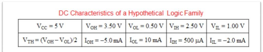
16 Lecture Summary Module 1-E Logic Levels and Noise Margins Reference: Digital Design Principles and Practices 4 th Ed. pp , 5 th Ed. pp overview o objective: to be able to design real circuits using CMOS or other logic families design margins need to ensure that the digital abstraction is valid for a given circuit need to provide adequate engineering design margins to ensure that a circuit will work properly under a variety of conditions need to be able to read and understand data sheets and specifications, in order to create reliable and robust real-world circuits and systems o noise the main reason for providing engineering design margins is to ensure proper operation in the presence of noise examples of noise sources: cosmic rays magnetic fields generated by machinery power supply disturbances the switching action of the logic circuits themselves o CMOS inverter input/output transfer characteristic o factors that cause the transfer characteristic typical, but not guaranteed to vary power supply voltage temperature output loading conditions under which a device was fabricated o sound engineering practice dictates that we use more conservative specifications for LOW and HIGH input/output voltage definitions o V OHmin - the minimum output voltage in the HIGH state o V IHmin - the minimum input voltage guaranteed to be recognized as a HIGH o V ILmax - the maximum input voltage guaranteed to be recognized as a LOW o V OLmax - the maximum output voltage in the LOW state 16
 o HC family (5-volt) CMOS data sheet")

 CMOS inputs")
 o CMOS device inputs are subject to damage from")
17 DC noise margin o definition: a measure of how much noise it takes to corrupt a worst-case output voltage into a value that may not be recognized properly by an input o calculation of DC noise margin (or the noise immunity margin ) o HC family (5-volt) CMOS data sheet DCNM = min (V OHmin V IHmin, V ILmax V OLmax ) For HC family (5-volt) CMOS: DCNM = min ( , ) = 1.25 v Q: Is a DCNM of 1.25 V good or bad? other gate input considerations o if the inputs to a CMOS circuit are not close to the Vcc / GND rails, the on transistor may not be fully on and the off transistor may not be fully off causing power dissipation of the device to increase o unused ( spare ) CMOS inputs should never be left unconnected ( floating ) a small amount of circuit noise can temporarily make a floating input look HIGH (solution: tie unused inputs high or low using a pull-up or pull-down resistor, respectively) o CMOS device inputs are subject to damage from electrostatic discharge (ESD) touch a source of earth ground before handling static sensitive devices or circuit boards that contain them 17
18 18

19 Lecture Summary Module 1-F Current Sourcing and Sinking Reference: Digital Design Principles and Practices 4 th Ed. pp , 5 th Ed. pp sourcing and sinking current o CMOS gate inputs have a very high impedance and consume very little current (about 1 microamp) from the circuits that drive them I IL - maximum current that flows into the input in the LOW state I IH - maximum current that flows into the input in the HIGH state o IC manufacturers specify a maximum load for the output in each state (HIGH or LOW) and guarantee a worst-case output voltage for that load I OL - maximum current that the output can sink in the LOW state while still maintaining an output voltage no greater than V OLmax I OH - maximum current that the output can source in the HIGH state while still maintaining an output voltage no less than V OHmin o sourcing/sinking sign convention CMOS loads vs. DC loads o often times gate outputs need to drive devices that require a non-trivial amount of current to operate called a resistive load or DC load o when driving a resistive load, the output of a CMOS circuit is not nearly as ideal as described previously (the output voltage swing may significantly degrade) o in either output state, the CMOS output transistor that is on has a non-zero resistance, and a load connected to its output terminal will cause a voltage drop across this resistance o consequently, most CMOS devices have two sets of loading specifications: CMOS loads device output connected to other CMOS inputs, which require very little current to recognize a high input or low input DC loads device output connected to resistive loads (devices that consume significant current, typically several milliamps) o example: inverter - current sourcing (DC load) 19
; the P-channel pull-up virtually disappears fan-out o definition: the number of gate inputs that a gate output")
 o practical fan-out is the minimum of the HIGH- and")
 = 20 Q: Is a fan-out of 20 good or bad?")
20 In the current SOURCING configuration, the inverter output is active high ( asserted high ); the N-channel pull-down virtually disappears o example: inverter current sinking (DC load) In the current SINKING configuration, the inverter output is active low ( asserted low ); the P-channel pull-up virtually disappears fan-out o definition: the number of gate inputs that a gate output can drive without exceeding its worst-case loading specifications o depends on characteristics of both the output device and the inputs being driven o must be examined for both the sourcing and sinking cases o limitations due to capacitive loading (impact on rise/fall times may be more of a limiting factor than fan-out or DCNM) o practical fan-out is the minimum of the HIGH- and LOW-state fan-outs Fan-out = min ( I OHmax / I IH, I OLmax / I IL ) For HC family (5-volt) CMOS: Fan-out = min ( I OHmax / I IH, I OLmax / I IL ) = min (0.02 ma / ma, ma / ma) = 20 Q: Is a fan-out of 20 good or bad? DC fan-out is considerably greater in this case if the output voltage swing is degraded but DCNM is lower and signal transitions times are longer, causing speed degradation 20
 or sourcing current")


21 driving LEDs o LEDS represent DC loads and can be interfaced to a CMOS gate output either by sinking current (LOW output) or sourcing current (HIGH output) Q: Which method is generally preferred (and why)? o example: worst case souring and sinking analysis for driving an LED sinking current V R = 5.0 V LED V OL = = 2.77 V use Max value indicated for V OL of 0.33 V R = V R /I OL = 2.77/0.004 = 693 P R = R x I OL 2 = 693 x (0.004) 2 = 11.1 milliwatts sourcing current Can also calculate power dissipation of resistor using V R I OL or (V R 2 )/R V R = V OH V LED = = 1.94 V use Min value indicated for V OH of 3.84 V R = V R /I OH = 1.94/0.004 = 485 P R = R x I OH 2 = 485 x (0.004) 2 = 7.8 milliwatts 21
22 effects of excessive loading o in the LOW state, the output voltage (V OL ) may increase beyond V OLmax o in the HIGH state, the output voltage (V O H) may fall below V OHmin o output rise and fall times may increase beyond their specifications (details in next section) o the operating temperature of the device may increase, thereby reducing the reliability of the device and eventually causing device failure example: a tale of two logic families o DCNM, AB o DCNM, BA o DCNM thought questions What is the consequence of a negative DCNM? What is the minimum DCNM required? 22

23 example: a tale of two logic families, continued o Fan-out, AB o Fan-out, BA CAUTION!! Current arrows for I O and I I point in opposite directions o Fan-out thought questions CAUTION!! Current arrows for I O and I I point in opposite directions Is it possible for the fan-out to be negative? What is the minimum fan-out required? 23


24 24


25 25

 depends on two characteristics: propagation delay transition time o logic gates require a certain amount of think time")
26 Lecture Summary Module 1-G Propagation Delay and Transition Time Reference: Digital Design Principles and Practices 4 th Ed. pp , 5 th Ed. pp overview o the speed and power dissipation of a CMOS device depend on the dynamic ( AC ) characteristics of the device and its load o logic designers must carefully examine the effects of output loading and redesign where the loading is too high o speed (performance) depends on two characteristics: propagation delay transition time o logic gates require a certain amount of think time to produce a new output in response to changing inputs referred to as the propagation delay of the gate o logic gate outputs can not change from a low voltage to a high voltage (or vice-versa) instantaneously referred to as the transition time of the gate o a timing diagram can be used to show how a logic circuit responds to time-varying input signals propagation delay o definition: the electrical path from a particular input signal of a logic element to its output signal is called a signal path o definition: the amount of time it takes for a change in an input signal to cause a corresponding change in a gate s output signal is called the propagation delay (t p ) o the propagation delay for an output signal going from LOW-to-HIGH (t PLH ) may be different than the propagation delay of that signal going from HIGH-to-LOW (t PHL ) The name used for the propagation delay (t PLH vs. t PHL ) is based on what the gate output is doing 26

27 propagation delay, continued o several factors lead to non-zero propagation delays in CMOS circuits: the rate at which transistors change state is influenced both by semiconductor physics and the circuit environment (input signal transition time, input capacitance, and output loading) multistage devices (e.g., non-inverting gates) may require several internal transistors to change state before the output can change state o example: propagation delay measurement The name used for the propagation delay (t PLH vs. t PHL ) is based on what the gate output is doing transition time o definition: the amount of time that the output of a logic circuit takes to change from one state to another rise time (t r or t TLH ): the time an output signal takes to transition from low-tohigh fall time (t f or t THL ): the time an output signal takes to transition from high-tolow o gate outputs can not change state instantaneously (i.e., with a transition time of zero) because they need to charge the stray capacitance of the wires and other components they drive The name used for the transition time (t TLH vs. t THL ) is based on what the gate output is doing The rise and fall times are typically not equal in value 27


28 transition time, continued o to avoid difficulties in defining the endpoints, transition times are normally measured one of two different ways: at the boundaries of the valid logic levels (i.e., V IHmin and V ILmax ) at the 10% and 90% points of the output waveform o using the valid logic level convention (above), the rise and fall times indicate how long it takes for an output signal to pass through the (undefined) indeterminate region between LOW and HIGH o example: transition time measurement / comparison of endpoints The name used for the transition time (t TLH vs. t THL ) is based on what the gate output is doing o transition time factors the transition times of a CMOS circuit depend mainly on two factors: the on transistor resistance the load capacitance stray capacitance (called an AC load ) arises from at least three different sources: output circuits including transistors, internal wiring, and packaging wiring that connects a gate output to other gate inputs input circuits including transistors, internal wiring, and packaging o equivalent circuit a gate output s load can be modeled by an equivalent load circuit with three components: R L and V L represent the DC load they determine the steady state voltages and currents present and do not have much effect on transition times C L represents the AC (capacitive) load it determines the voltages and currents present while the output is changing, as well as how long it takes to change from one state to another 28


29 transition time, continued o model for low-to-high transition o model for high-to-low transition 29
 load C L = 200 pf, calculate")

 load C L = 200 pf, estimate the fall time and rise time capacitive load conclusions o an increase in load capacitance causes an increase in the RC time constant and a corresponding increase in")
30 transition time, continued o example: given that a CMOS inverter s P-channel MOSFET has an ON resistance of 200, that its N-channel MOSFET has an ON resistance of 100, and that the capacitive (or AC) load C L = 200 pf, calculate the fall time Calculated transition times are sensitive to the choice of logic levels (i.e., V IHmin and V ILmax ) o transition time estimation ( rule of thumb ) - in practical circuits, the transition time can be estimated using the RC time constant of the charging or discharging circuit o example: given that a CMOS inverter s P-channel MOSFET has an ON resistance of 200, that its N-channel MOSFET has an ON resistance of 100, and that the capacitive (or A.C. ) load C L = 200 pf, estimate the fall time and rise time capacitive load conclusions o an increase in load capacitance causes an increase in the RC time constant and a corresponding increase in the output transition (rise/fall) times o load capacitance must be minimized to obtain high circuit performance this can be achieved by: minimizing the number of inputs driven by a given signal creating multiple copies of the signal (using buffers ) careful physical layout of the circuit 30
31 31
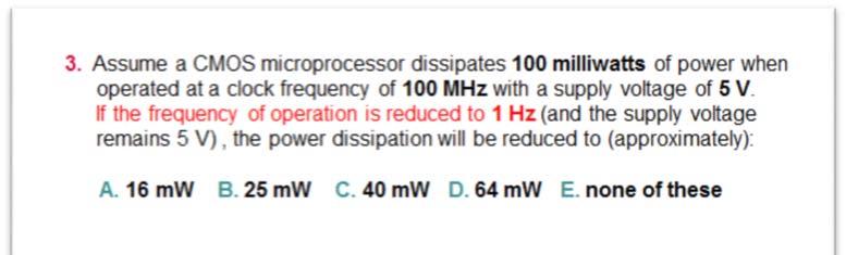
32 Lecture Summary Module 1-H Power Consumption and Decoupling Reference: Digital Design Principles and Practices 4 th Ed. pp , 5 th Ed. pp overview o definition: the power dissipation (consumption) of a CMOS circuit whose output is not changing is called static (quiescent) power dissipation o most CMOS circuits have very low static power dissipation o CMOS circuits only dissipate a significant amount of power during transitions this is called dynamic power dissipation sources of dynamic power dissipation: o the partial short-circuiting of the CMOS output structure (e.g., when the input voltage is not close to one of the power supply rails) called P T (power due to output transitions) o the capacitive load on the output (power is dissipated in the on resistance of the active transistor to charge/discharge the capacitive load) called P L (power due to charging/discharging load) o total dynamic power dissipation (P T + P L ) is proportional to the square of the power supply voltage times the transition frequency conclusions: o power dissipation increases linearly as the frequency of operation increases o reducing the power supply voltage results in a quadratic reduction of the power dissipation example: a microcontroller can operate over a frequency range of 0 Hz to 10 MHz, and dissipates 100 mw when operated at 10 MHz; plot its power dissipation over the specified frequency range Power Dissipation (mw) Clock Frequency (MHz) 32
 100 90 80 70 60 50 40 30 20 10 0 100 x (4/5) 2 = 64 100 x (3/5) 2 = 36 100 x (2/5) 2 = 16 100 x (1/5) 2 = 4 1 2 3 4 5 Power Supply Voltage current spikes and decoupling o when a CMOS")
33 example: a microcontroller can operate over a power supply range of 1 to 5 volts, and dissipates 100 mw when operated at 5 VDC; plot its power dissipation over the specified power supply range Power Dissipation (mw) x (4/5) 2 = x (3/5) 2 = x (2/5) 2 = x (1/5) 2 = Power Supply Voltage current spikes and decoupling o when a CMOS gate output changes state, the P- and N-channel transistors are both partially on simultaneously, causing a current spike o current spikes often show up as noise on the power supply and ground connections o decoupling capacitors (between Vcc and GND) must be distributed throughout a printed circuit board (PCB) to serve as a source of instantaneous current during output transitions this helps mitigate noise and improve signal quality o decoupling capacitors should be located as physically close as possible to each IC o use 0.1 F decoupling capacitors for system frequencies up to 15 MHz; above 15 MHz, use 0.01 F decoupling capacitors 33

34 34

35 Lecture Summary Module 1-I Schmitt Triggers and Transmission Gates Reference: Digital Design Principles and Practices 4 th Ed. pp , 5 th Ed overview o the basic CMOS circuit has been tailored in many ways to produce gates for specific applications o this circuit tailoring has been motivated by the need for: higher performance than can be achieved with standard NAND/NOR gates conditioning noisy, slowly changing logic signals allowing logic elements to communicate via buses Schmitt-trigger inputs o a Schmitt trigger is a special circuit that shifts the switching threshold depending on whether the input is changing from LOW-to-HIGH (V T+ ) or from HIGH-to-LOW (V T- ) o the difference between the two thresholds is called hysteresis o comparison of Schmitt trigger with regular (single-threshold) inverter 35
36 Schmitt-trigger inputs, continued o observations Schmitt-trigger inputs have better noise immunity margin than ordinary gates for noisy or slowly changing signals distorted logic signals of this type typically occur in physically long connections, such as I/O buses and computer interface cables o rule of foot - logic-level signals can be sent reliably over a cable for only a few feet transmission gates o the P- and N-channel transistor pair can be connected together to form a logic-controlled switch, called a transmission gate o control signals EN_L and EN are at opposite levels o when EN is asserted, there is a low-impedance connection between A and B; when EN is negated, A and B are disconnected A high performance multiplexer (input selector switch) can be constructed using a pair of transmission gates and an inverter 36


37 Lecture Summary Module 1-J Three-State and Open-Drain Outputs Reference: Digital Design Principles and Practices 4 th Ed. pp , ; 5 th Ed. pp , three-state ( tri-state ) outputs o definition: a gate output that has a third electrical state is called a three-state output (or tri-state output) o this third electrical state is called the high impedance, Hi-Z, or floating state o in the high impedance state, the gate output effectively appears to be disconnected from the rest of the circuit o three-state devices have an extra input, typically called the Output Enable (OE), for enabling data to flow through the device (when asserted) or placing the output in the high impedance state (when negated) o revisit basic CMOS output circuit 37

38 three-state ( tri-state ) outputs, continued o applications the most common use of tri-state buffers is to create data buses over which digital subsystems can (bi-directionally) send and receive data definition: a bus is a collection of signals with a common purpose (e.g., sending the address of an item in memory, sending the data to be written to memory) a bus transceiver contains pairs of tri-state buffers connected in opposite directions between each pair of pins, so that data can be transferred in either direction o float delay tri-state outputs are typically designed so that they go into the Hi-Z (high impedance) state faster than they come out of the Hi-Z state (i.e., t plz and t phz are both less than t pzl and t pzh ) the time it takes to go from a driven state (valid logic level) to the Hi-Z floating state is called the float delay given this rule, if one tri-state device is disabled and another tri-state device is enabled simultaneously, then the first device will get off the bus before the second one gets on this helps prevent fighting open-drain outputs o definition: a CMOS output structure that does not include a P-channel (pull-up) transistor is called an open-drain output o an open-drain output is in one of two states: LOW or open (i.e., disconnected) o an underscored diamond (or O.D. ) is used to indicate that an output is open drain o an open-drain output requires an external pull-up resistor to passively pull it high in the open state (since the output structure does NOT include a P-channel active pull-up) 38
 o application - wired logic (definition: wired logic is performed if the outputs of several open-drain gates are tied together")

39 open-drain outputs, continued o application driving LEDs (O.D. outputs can typically sink more current than conventional gates) o application - wired logic (definition: wired logic is performed if the outputs of several open-drain gates are tied together with a single pull-up resistor) o pull-up resistor calculations in open-drain applications, two calculations bracket the allowable values of the pull-up resistor R: LOW - the sum of the current through R plus the LOW state input currents of the gate inputs driven must not exceed the I OLmax of the active device HIGH - the voltage drop across R in the HIGH state must not reduce the output voltage below the V IHmin of the driven gate inputs o example: calculate a suitable value of pull-up resistor to use with the following circuit: 5 V O.D. 1 2 Specifications (hypothetical data): Off-state leakage current of O.D. NAND gate output: +3 A I IH and I IL required by inverter input: ±1 A V IH desired for inverter input: 4.9 V I OLmax of O.D. NAND gate output: +10 V OL = 0.3 V O.D O.D. 39
 to 10,000 (R max ) will satisfy the")
")
40 open-drain outputs, continued o pull-up resistor calculation example, continued solution, maximum R Value based on V IH desired Conclusion A pull-up resistor ranging from 470 (R min ) to 10,000 (R max ) will satisfy the specified constraints solution, minimum R Value based on I OL max of one gate NOTE: Picking R min will minimize the rise time, while picking R max will minimize the power dissipation prove the worst case scenario (R = 470 ) 40


41 open-drain outputs, continued o pull-up resistor calculation example, continued proof, continued conclusions compare power dissipation of circuit using R min vs. R max as the pull-up resistor 41


42 open-drain outputs, continued o pull-up resistor calculation example, continued power dissipation comparison, continued compare rise time estimates of circuit using R min vs. R max as the pull-up resistor o example: estimate the on resistance of an O.D. gate and pull-up resistor value based on rise/fall times 42


43 43
Lecture Summary Module 1 Switching Algebra and CMOS Logic Gates
 Lecture Summary Module 1 Switching Algebra and CMOS Logic Gates Learning Outcome: an ability to analyze and design CMOS logic gates Learning Objectives: 1-1. convert numbers from one base (radix) to another:
Lecture Summary Module 1 Switching Algebra and CMOS Logic Gates
 Lecture Summary Module 1 Switching Algebra and CMOS Logic Gates Learning Outcome: an ability to analyze and design CMOS logic gates Learning Objectives: 1-1. convert numbers from one base (radix) to another:
2019 by D. G. Meyer 1
 Purdue IM:PACT* *Instruction Matters: Purdue Academic Course Transformation Introduction to Digital System Design Module Switching Algebra and CMOS ogic Gates Glossary of Common Terms INTEGRATED CIRCUIT
Practice Homework Problems for Module 1
 Practice Homework Problems for Module 1 1. Unsigned base conversions (LO 1-1). (a) (2C9E) 16 to base 2 (b) (1101001) 2 to base 10 (c) (1101001) 2 to base 16 (d) (8576) 10 to base 16 (e) (A27F) 16 to base
Digital logic families
 Digital logic families Digital logic families Digital integrated circuits are classified not only by their complexity or logical operation, but also by the specific circuit technology to which they belong.
Classification of Digital Circuits
 Classification of Digital Circuits Combinational logic circuits. Output depends only on present input. Sequential circuits. Output depends on present input and present state of the circuit. Combinational
Note that none of the above MAY be a VALID ANSWER.
 ECE 270 Learning Outcome 1-1 - Practice Exam / Solution LEARNING OUTCOME #1: an ability to analyze and design CMOS logic gates. Multiple Choice select the single most appropriate response for each question.
ECE/CoE 0132: FETs and Gates
 ECE/CoE 0132: FETs and Gates Kartik Mohanram September 6, 2017 1 Physical properties of gates Over the next 2 lectures, we will discuss some of the physical characteristics of integrated circuits. We will
Lab Project #2: Small-Scale Integration Logic Circuits
 Lab Project #2: Small-Scale Integration Logic Circuits Duration: 2 weeks Weeks of 1/31/05 2/7/05 1 Objectives The objectives of this laboratory project are to design some simple logic circuits using small-scale
Lecture 02: Logic Families. R.J. Harris & D.G. Bailey
 Lecture 02: Logic Families R.J. Harris & D.G. Bailey Objectives Show how diodes can be used to form logic gates (Diode logic). Explain the need for introducing transistors in the output (DTL and TTL).
Basic Characteristics of Digital ICs
 ECEN202 Section 2 Characteristics of Digital IC s Part 1: Specification of characteristics An introductory look at digital IC s: Logic families Basic construction and operation Operating characteristics
DO NOT COPY DO NOT COPY
 184 hapter 3 Digital ircuits Table 3-13 Manufacturers logic data books. Manufacturer Order Number Topics Title Year Texas Instruments SDLD001 74, 74S, 74LS TTL TTL Logic Data Book 1988 Texas Instruments
Microcontroller Systems. ELET 3232 Topic 13: Load Analysis
 Microcontroller Systems ELET 3232 Topic 13: Load Analysis 1 Objective To understand hardware constraints on embedded systems Define: Noise Margins Load Currents and Fanout Capacitive Loads Transmission
EE 42/100 Lecture 23: CMOS Transistors and Logic Gates. Rev A 4/15/2012 (10:39 AM) Prof. Ali M. Niknejad
 Prof. Ali M. Niknejad") A. M. Niknejad University of California, Berkeley EE 100 / 42 Lecture 23 p. 1/16 EE 42/100 Lecture 23: CMOS Transistors and Logic Gates ELECTRONICS Rev A 4/15/2012 (10:39 AM) Prof. Ali M. Niknejad University
A. M. Niknejad University of California, Berkeley EE 100 / 42 Lecture 23 p. 1/16 EE 42/100 Lecture 23: CMOS Transistors and Logic Gates ELECTRONICS Rev A 4/15/2012 (10:39 AM) Prof. Ali M. Niknejad University
Digital Circuits and Operational Characteristics
 Digital Circuits and Operational Characteristics 1. DC Supply Voltage TTL based devices work with a dc supply of +5 Volts. TTL offers fast switching speed, immunity from damage due to electrostatic discharges.
Digital Electronics Part II - Circuits
 Digital Electronics Part II - Circuits Dr. I. J. Wassell Gates from Transistors 1 Introduction Logic circuits are non-linear, consequently we will introduce a graphical technique for analysing such circuits
Module-1: Logic Families Characteristics and Types. Table of Content
 1 Module-1: Logic Families Characteristics and Types Table of Content 1.1 Introduction 1.2 Logic families 1.3 Positive and Negative logic 1.4 Types of logic families 1.5 Characteristics of logic families
Digital Microelectronic Circuits ( ) CMOS Digital Logic. Lecture 6: Presented by: Adam Teman
 CMOS Digital Logic. Lecture 6: Presented by: Adam Teman") Digital Microelectronic Circuits (361-1-3021 ) Presented by: Adam Teman Lecture 6: CMOS Digital Logic 1 Last Lectures The CMOS Inverter CMOS Capacitance Driving a Load 2 This Lecture Now that we know all
Digital Microelectronic Circuits (361-1-3021 ) Presented by: Adam Teman Lecture 6: CMOS Digital Logic 1 Last Lectures The CMOS Inverter CMOS Capacitance Driving a Load 2 This Lecture Now that we know all
74ALVC Low Voltage 16-Bit Bidirectional Transceiver with 3.6V Tolerant Inputs and Outputs and 26Ω Series Resistors in A Port Outputs
 74ALVC162245 Low Voltage 16-Bit Bidirectional Transceiver with 3.6V Tolerant Inputs and Outputs and 26Ω Series Resistors in A Port Outputs General Description The ALVC162245 contains sixteen non-inverting
SP26LV431 HIGH SPEED +3.3V QUAD RS-422 DIFFERENTIAL LINE DRIVER
 HIGH SPEED +3.3V QUAD RS-422 DIFFERENTIAL LINE DRIVER JUNE 2011 REV. 1.1.1 GENERAL DESCRIPTION The SP26LV431 is a quad differential line driver that meets the specifications of the EIA standard RS-422
QS54/74FCT373T, 2373T. High-Speed CMOS Bus Interface 8-Bit Latches MDSL QUALITY SEMICONDUCTOR, INC. 1 DECEMBER 28, 1998
 Q QUALITY SEMICONDUCTOR, INC. QS54/74FCT373T, 2373T High-Speed CMOS Bus Interface 8-Bit Latches QS54/74FCT373T QS54/74FCT2373T FEATURES/BENEFITS Pin and function compatible to the 74F373 74FCT373 and 74ABT373
IC Logic Families. Wen-Hung Liao, Ph.D. 5/16/2001
 IC Logic Families Wen-Hung Liao, Ph.D. 5/16/2001 Digital IC Terminology Voltage Parameters: V IH (min): high-level input voltage, the minimum voltage level required for a logic 1 at an input. V IL (max):
Lecture 16. Complementary metal oxide semiconductor (CMOS) CMOS 1-1
 CMOS 1-1") Lecture 16 Complementary metal oxide semiconductor (CMOS) CMOS 1-1 Outline Complementary metal oxide semiconductor (CMOS) Inverting circuit Properties Operating points Propagation delay Power dissipation
Lecture 16 Complementary metal oxide semiconductor (CMOS) CMOS 1-1 Outline Complementary metal oxide semiconductor (CMOS) Inverting circuit Properties Operating points Propagation delay Power dissipation
Quad 2-Input NAND Gate High-Voltage Silicon-Gate CMOS
 TECHNICAL DATA Quad 2-Input NAND Gate High-oltage Silicon-Gate CMOS The NAND gates provide the system designer with direct emplementation of the NAND function. Operating oltage Range:.0 to 18 Maximum input
Logic Families. Describes Process used to implement devices Input and output structure of the device. Four general categories.
 Logic Families Characterizing Digital ICs Digital ICs characterized several ways Circuit Complexity Gives measure of number of transistors or gates Within single package Four general categories SSI - Small
FST Bit Low Power Bus Switch
 2-Bit Low Power Bus Switch General Description The FST3306 is a 2-bit ultra high-speed CMOS FET bus switch with TTL-compatible active LOW control inputs. The low on resistance of the switch allows inputs
ECE 301 Digital Electronics
 ECE 301 Digital Electronics Constraints in Logic Circuit Design (Lecture #14) The slides included herein were taken from the materials accompanying Fundamentals of Logic Design, 6 th Edition, by Roth and
ECE 334: Electronic Circuits Lecture 10: Digital CMOS Circuits
 Faculty of Engineering ECE 334: Electronic Circuits Lecture 10: Digital CMOS Circuits CMOS Technology Complementary MOS, or CMOS, needs both PMOS and NMOS FET devices for their logic gates to be realized
CD74HC4067, CD74HCT4067
 Data sheet acquired from Harris Semiconductor SCHS209 February 1998 CD74HC4067, CD74HCT4067 High-Speed CMOS Logic 16-Channel Analog Multiplexer/Demultiplexer [ /Title (CD74 HC406 7, CD74 HCT40 67) /Subject
Digital Microelectronic Circuits ( ) Terminology and Design Metrics. Lecture 2: Presented by: Adam Teman
 Terminology and Design Metrics. Lecture 2: Presented by: Adam Teman") Digital Microelectronic Circuits (361-1-3021 ) Presented by: Adam Teman Lecture 2: Terminology and Design Metrics 1 Last Week Introduction» Moore s Law» History of Computers Circuit analysis review» Thevenin,
Digital Microelectronic Circuits (361-1-3021 ) Presented by: Adam Teman Lecture 2: Terminology and Design Metrics 1 Last Week Introduction» Moore s Law» History of Computers Circuit analysis review» Thevenin,
SP26LV432 HIGH SPEED +3.3V QUAD RS-422 DIFFERENTIAL LINE RECEIVER
 HIGH SPEED +3.3V QUAD RS-422 DIFFERENTIAL LINE RECEIVER JUNE 2011 REV. 1.0.1 GENERAL DESCRIPTION The SP26LV432 is a quad differential line receiver with three-state outputs designed to meet the EIA specifications
MIC4421/4422. Bipolar/CMOS/DMOS Process. General Description. Features. Applications. Functional Diagram. 9A-Peak Low-Side MOSFET Driver
 9A-Peak Low-Side MOSFET Driver Micrel Bipolar/CMOS/DMOS Process General Description MIC4421 and MIC4422 MOSFET drivers are rugged, efficient, and easy to use. The MIC4421 is an inverting driver, while
The entire range of digital ICs is fabricated using either bipolar devices or MOS devices or a combination of the two. Bipolar Family DIODE LOGIC
 Course: B.Sc. Applied Physical Science (Computer Science) Year & Sem.: IInd Year, Sem - IIIrd Subject: Computer Science Paper No.: IX Paper Title: Computer System Architecture Lecture No.: 10 Lecture Title:
Implications of Slow or Floating CMOS Inputs
 Implications of Slow or Floating CMOS Inputs SCBA4 13 1 IMPORTANT NOTICE Texas Instruments (TI) reserves the right to make changes to its products or to discontinue any semiconductor product or service
FSTD Bit Bus Switch with Level Shifting
 FSTD16861 20-Bit Bus Switch with Level Shifting General Description The Fairchild Switch FSTD16861 provides 20-bits of highspeed CMOS TTL-compatible bus switching. The low On Resistance of the switch allows
Logic Families. A-PDF Split DEMO : Purchase from to remove the watermark. 5.1 Logic Families Significance and Types. 5.1.
 A-PDF Split DEMO : Purchase from www.a-pdf.com to remove the watermark 5 Logic Families Digital integrated circuits are produced using several different circuit configurations and production technologies.
Designing Information Devices and Systems II Fall 2017 Note 1
 EECS 16B Designing Information Devices and Systems II Fall 2017 Note 1 1 Digital Information Processing Electrical circuits manipulate voltages (V ) and currents (I) in order to: 1. Process information
FST Bit Bus Switch
 Features 4 Ω Switch Connection between Two Ports Minimal Propagation Delay through the Switch Low I CC Zero Bounce in Flow-through Mode Control Inputs Compatible with TTL Level Description December 2012
74VHC4046 CMOS Phase Lock Loop
 74VHC4046 CMOS Phase Lock Loop General Description The 74VHC4046 is a low power phase lock loop utilizing advanced silicon-gate CMOS technology to obtain high frequency operation both in the phase comparator
74ALVC16500 Low Voltage 18-Bit Universal Bus Transceivers with 3.6V Tolerant Inputs and Outputs
 Low Voltage 18-Bit Universal Bus Transceivers with 3.6V Tolerant Inputs and Outputs General Description The ALVC16500 is an 18-bit universal bus transceiver which combines D-type latches and D-type flip-flops
Obsolete Product(s) - Obsolete Product(s)
 - Obsolete Product(s)") OCTAL BUS TRANSCEIVER WITH 3 STATE OUTPUTS (INVERTED) HIGH SPEED: t PD = 13ns (TYP.) at V CC = 4.5V LOW POWER DISSIPATION: I CC = 4µA(MAX.) at T A =25 C COMPATIBLE WITH TTL OUTPUTS : V IH = 2V (MIN.) V
OCTAL BUS TRANSCEIVER WITH 3 STATE OUTPUTS (INVERTED) HIGH SPEED: t PD = 13ns (TYP.) at V CC = 4.5V LOW POWER DISSIPATION: I CC = 4µA(MAX.) at T A =25 C COMPATIBLE WITH TTL OUTPUTS : V IH = 2V (MIN.) V
In this experiment you will study the characteristics of a CMOS NAND gate.
 Introduction Be sure to print a copy of Experiment #12 and bring it with you to lab. There will not be any experiment copies available in the lab. Also bring graph paper (cm cm is best). Purpose In this
DIGITAL ELECTRONICS. Digital Electronics - B1 28/04/ DDC Storey 1. Group B: Digital circuits and devices
 Politecnico di Torino - ICT school Group B: Digital circuits and devices DIGITAL ELECTRONICS B DIGITAL CIRCUITS B.1 Logic devices B1 B2 B3 B4 Logic families Combinatorial circuits Basic sequential circuits
36 Logic families and
 Unit 4 Outcomes 1. Demonstrate an understanding of logic families and their terms used in their specifications 2. Demonstrate an understanding of time division multiplex (TDM) 3. Demonstrate an understanding
NC7SZD384 1-Bit Low Power Bus Switch with Level Shifting
 1-Bit Low Power Bus Switch with Level Shifting General Description The NC7SZD384 provides 1-bit of high-speed CMOS TTL-compatible bus switch. The low on resistance of the switch allows inputs to be connected
M74HC14. Hex Schmitt inverter. Features. Description
 Hex Schmitt inverter Features High speed: t PD =12 ns (typ.) at CC = 6 Low power dissipation: I CC = 1 μa (max.) at T A =25 C High noise immunity: H = 1.2 (typ.) at CC = 6 Symmetrical output impedance:
Place answers on the supplied BUBBLE SHEET only nothing written here will be graded.
 ECE 270 Learning Outcome 1-1 - Practice Exam B OUTCOME #1: an ability to analyze and design CMOS logic gates. Multiple Choice select the single most appropriate response for each question. Note that none
TC74HC540AP,TC74HC540AF,TC74HC540AFW TC74HC541AP,TC74HC541AF,TC74HC541AFW
 TOSHIBA CMOS Digital Integrated Circuit Silicon Monolithic TC74HC540,541AP/AF/AFW TC74HC540AP,TC74HC540AF,TC74HC540AFW TC74HC541AP,TC74HC541AF,TC74HC541AFW Octal Bus Buffer TC74HC540AP/AF/AFW TC74HC541AP/AF/AFW
FST Bit to 32-Bit Multiplexer/Demultiplexer Bus Switch
 September 1997 Revised November 2000 FST16233 16-Bit to 32-Bit Multiplexer/Demultiplexer Bus Switch General Description The Fairchild Switch FST16233 is a 16-bit to 32-bit highspeed CMOS TTL-compatible
Features. Applications
 HCPL-9000/-0900, -900/-090, HCPL-90/-09, -900J/-090J, HCPL-90J/-09J, -90J/-09J High Speed Digital Isolators Data Sheet Lead (Pb) Free RoHS 6 fully compliant RoHS 6 fully compliant options available; -xxxe
CMOS the Ideal Logic Family
 CMOS the Ideal Logic Family National Semiconductor Application Note 77 Stephen Calebotta January 1983 INTRODUCTION Let s talk about the characteristics of an ideal logic family It should dissipate no power
M74HCT244TTR OCTAL BUS BUFFER WITH 3 STATE OUTPUTS (NON INVERTED)
") OCTAL BUS BUFFER WITH 3 STATE OUTPUTS (NON INVERTED) HIGH SPEED: t PD = 15 ns (TYP.) at V CC = 4.5V LOW POWER DISSIPATION: I CC = 4µA(MAX.) at T A =25 C COMPATIBLE WITH TTL OUTPUTS : V IH = 2V (MIN.) V
OCTAL BUS BUFFER WITH 3 STATE OUTPUTS (NON INVERTED) HIGH SPEED: t PD = 15 ns (TYP.) at V CC = 4.5V LOW POWER DISSIPATION: I CC = 4µA(MAX.) at T A =25 C COMPATIBLE WITH TTL OUTPUTS : V IH = 2V (MIN.) V
I. Digital Integrated Circuits - Logic Concepts
 I. Digital Integrated Circuits - Logic Concepts. Logic Fundamentals: binary mathematics: only operate on and (oolean algebra) simplest function -- inversion = symbol for the inverter INPUT OUTPUT EECS
CD74HC534, CD74HCT534, CD74HC564, CD74HCT564
 Data sheet acquired from Harris Semiconductor SCHS188 January 1998 CD74HC534, CD74HCT534, CD74HC564, CD74HCT564 High Speed CMOS Logic Octal D-Type Flip-Flop, Three-State Inverting Positive-Edge Triggered
MM74HC132 Quad 2-Input NAND Schmitt Trigger
 Quad 2-Input NAND Schmitt Trigger General Description The utilizes advanced silicon-gate CMOS technology to achieve the low power dissipation and high noise immunity of standard CMOS, as well as the capability
Multiplexer for Capacitive sensors
 DATASHEET Multiplexer for Capacitive sensors Multiplexer for Capacitive Sensors page 1/7 Features Very well suited for multiple-capacitance measurement Low-cost CMOS Low output impedance Rail-to-rail digital
M74HCT574TTR OCTAL D-TYPE FLIP FLOP WITH 3 STATE OUTPUT NON INVERTING
 OCTAL D-TYPE FLIP FLOP WITH 3 STATE OUTPUT NON INVERTING HIGH SPEED: f MAX = 50MHz (TYP.) at V CC = 4.5V LOW POWER DISSIPATION: I CC = 4µA(MAX.) at T A =25 C COMPATIBLE WITH TTL OUTPUTS : V IH = 2V (MIN.)
74LVC16245A/ 74LVCH16245A 16-bit bus transceiver with direction pin; 5V tolerant (3-State)
") INTEGRATED CIRCUITS 16-bit bus transceiver with direction pin; 5V tolerant Supersedes data of 1997 Aug 1 IC24 Data Handbook 1997 Sep 25 FEATURES 5 volt tolerant inputs/outputs for interfacing with 5V logic
INTEGRATED CIRCUITS 16-bit bus transceiver with direction pin; 5V tolerant Supersedes data of 1997 Aug 1 IC24 Data Handbook 1997 Sep 25 FEATURES 5 volt tolerant inputs/outputs for interfacing with 5V logic
Chapter 1: Digital logic
 Chapter 1: Digital logic I. Overview In PHYS 252, you learned the essentials of circuit analysis, including the concepts of impedance, amplification, feedback and frequency analysis. Most of the circuits
Chapter 6 Digital Circuit 6-6 Department of Mechanical Engineering
 MEMS1082 Chapter 6 Digital Circuit 6-6 TTL and CMOS ICs, TTL and CMOS output circuit When the upper transistor is forward biased and the bottom transistor is off, the output is high. The resistor, transistor,
FST32X Bit Bus Switch
 FST32X245 16-Bit Bus Switch General Description The Fairchild Switch FST32X245 provides 16-bits of high speed CMOS TTL-compatible bus switching in a standard flow-through mode. The low On Resistance of
M74HC251TTR 8-CHANNEL MULTIPLEXER (3-STATE)
") 8-CHANNEL MULTIPLEXER (3-STATE) HIGH SPEED : t PD = 17 ns (TYP.) at V CC = 6V LOW POWER DISSIPATION: I CC =4µA(MAX.) at T A =25 C HIGH NOISE IMMUNITY: V NIH = V NIL = 28 % V CC (MIN.) SYMMETRICAL OUTPUT
8-CHANNEL MULTIPLEXER (3-STATE) HIGH SPEED : t PD = 17 ns (TYP.) at V CC = 6V LOW POWER DISSIPATION: I CC =4µA(MAX.) at T A =25 C HIGH NOISE IMMUNITY: V NIH = V NIL = 28 % V CC (MIN.) SYMMETRICAL OUTPUT
Adaptive Power MOSFET Driver 1
 Adaptive Power MOSFET Driver 1 FEATURES dv/dt and di/dt Control Undervoltage Protection Short-Circuit Protection t rr Shoot-Through Current Limiting Low Quiescent Current CMOS Compatible Inputs Compatible
NC7S14 TinyLogic HS Inverter with Schmitt Trigger Input
 January 1996 Revised August 2004 NC7S14 TinyLogic HS Inverter with Schmitt Trigger Input General Description The NC7S14 is a single high performance CMOS Inverter with Schmitt Trigger input. The circuit
TC74HC240AP,TC74HC240AF,TC74HC240AFW TC74HC241AP,TC74HC241AF TC74HC244AP,TC74HC244AF,TC74HC244AFW
 TOSHIBA CMOS Digital Integrated Circuit Silicon Monolithic TC74HC240AP,TC74HC240AF,TC74HC240AFW TC74HC241AP,TC74HC241AF TC74HC244AP,TC74HC244AF,TC74HC244AFW Octal Bus Buffer TC74HC240AP/AF/AFW TC74HC241AP/AF
ECE 484 VLSI Digital Circuits Fall Lecture 02: Design Metrics
 ECE 484 VLSI Digital Circuits Fall 2016 Lecture 02: Design Metrics Dr. George L. Engel Adapted from slides provided by Mary Jane Irwin (PSU) [Adapted from Rabaey s Digital Integrated Circuits, 2002, J.
INTRODUCTION LOGIC SIGNALS AND GATES A logic value, 0 or 1, is often called a binary digit, or bit. If an application requires more than two discrete
 INTRODUCTION LOGIC SIGNALS AND GATES A logic value, 0 or 1, is often called a binary digit, or bit. If an application requires more than two discrete values, additional bits may be used, with a set of
CHAPTER 6 DIGITAL CIRCUIT DESIGN USING SINGLE ELECTRON TRANSISTOR LOGIC
 94 CHAPTER 6 DIGITAL CIRCUIT DESIGN USING SINGLE ELECTRON TRANSISTOR LOGIC 6.1 INTRODUCTION The semiconductor digital circuits began with the Resistor Diode Logic (RDL) which was smaller in size, faster
Embedded Systems. Oscillator and I/O Hardware. Eng. Anis Nazer First Semester
 Embedded Systems Oscillator and I/O Hardware Eng. Anis Nazer First Semester 2016-2017 Oscillator configurations Three possible configurations for Oscillator (a) using a crystal oscillator (b) using an
DC Electrical Characteristics of MM74HC High-Speed CMOS Logic
 DC Electrical Characteristics of MM74HC High-Speed CMOS Logic The input and output characteristics of the MM74HC high-speed CMOS logic family were conceived to meet several basic goals. These goals are
COURSE LEARNING OUTCOMES AND OBJECTIVES
 COURSE LEARNING OUTCOMES AND OBJECTIVES A student who successfully fulfills the course requirements will have demonstrated: 1. an ability to analyze and design CMOS logic gates 1-1. convert numbers from
PI3C3305/PI3C3306. Features. Description. Applications. PI3C3306 Block Diagram. PI3C3305 Block Diagram. PI3C Pin Configuration
 2.5V/3., High-Bandwidth, Hot-Insertion, 2-Bit, 2-Port Bus Switch w/ Individual Enables Features Near-Zero propagation delay 5Ω switches connect inputs to outputs High Bandwidth (>400 MHz) Rail-to-Rail,
EXPERIMENT 12: DIGITAL LOGIC CIRCUITS
 EXPERIMENT 12: DIGITAL LOGIC CIRCUITS The purpose of this experiment is to gain some experience in the use of digital logic circuits. These circuits are used extensively in computers and all types of electronic
74ACT541TTR OCTAL BUS BUFFER WITH 3 STATE OUTPUTS (NON INVERTED)
") OCTAL BUS BUFFER WITH 3 STATE OUTPUTS (NON INVERTED) HIGH SPEED: t PD = 4ns (TYP.) at V CC = 5V LOW POWER DISSIPATION: I CC = 4µA(MAX.) at T A =25 C COMPATIBLE WITH TTL OUTPUTS V IH = 2V (MIN.), V IL =
OCTAL BUS BUFFER WITH 3 STATE OUTPUTS (NON INVERTED) HIGH SPEED: t PD = 4ns (TYP.) at V CC = 5V LOW POWER DISSIPATION: I CC = 4µA(MAX.) at T A =25 C COMPATIBLE WITH TTL OUTPUTS V IH = 2V (MIN.), V IL =
PI3C V/3.3V, High Bandwidth, Hot Insertion 8-Bit, 2-Port, Bus Switch. Description. Features. Pin Configuration. Block Diagram.
 Features Near-Zero propagation delay 5-ohm switches connect inputs to outputs High Bandwidth Operation (>400 MHz) Permits Hot Insertion 5V I/O Tolerant Rail-to-Rail 3.3V or 2.5V Switching 2.5V Supply Voltage
74HC7540; 74HCT7540. Octal Schmitt trigger buffer/line driver; 3-state; inverting
 Rev. 5 26 May 2016 Product data sheet 1. General description 2. Features and benefits The is an 8-bit inverting buffer/line driver with Schmitt-trigger inputs and 3-state outputs. The device features two
74VHCT244ATTR OCTAL BUS BUFFER WITH 3 STATE OUTPUTS (NON INVERTED)
") OCTAL BUS BUFFER WITH 3 STATE OUTPUTS (NON INVERTED) HIGH SPEED: t PD = 5.4 ns (TYP.) at V CC = 5V LOW POWER DISSIPATION: I CC = 4 µa (MAX.) at T A =25 C COMPATIBLE WITH TTL OUTPUTS: V IH = 2V (MIN.),
OCTAL BUS BUFFER WITH 3 STATE OUTPUTS (NON INVERTED) HIGH SPEED: t PD = 5.4 ns (TYP.) at V CC = 5V LOW POWER DISSIPATION: I CC = 4 µa (MAX.) at T A =25 C COMPATIBLE WITH TTL OUTPUTS: V IH = 2V (MIN.),
UT54ACS164245S/SE Schmitt CMOS 16-bit Bidirectional MultiPurpose Transceiver Datasheet
 UT54ACS164245S/SE Schmitt CMOS 16-bit Bidirectional MultiPurpose Transceiver Datasheet April 2016 www.aeroflex.com/16bitlogic FEATURES Voltage translation - 5V bus to 3.3V bus - 3.3V bus to 5V bus Cold
4-bit counter circa bit counter circa 1990
 Digital Logic 4-bit counter circa 1960 8-bit counter circa 1990 Logic gates Operates on logical values (TRUE = 1, FALSE = 0) NOT AND OR XOR 0-1 1-0 0 0 0 1 0 0 0 1 0 1 1 1 0 0 0 1 0 1 0 1 1 1 1 1 0 0 0
CD54/74HC240, CD54/74HCT240, CD74HC241, CD54/74HCT241, CD54/74HC244, CD54/74HCT244 High Speed CMOS Logic Octal Buffer/Line Drivers, Three-State
 Data sheet acquired from Harris Semiconductor SCHS167A November 1997 - Revised May 2000 CD54/74HC240, CD54/74HCT240, HC241, CD54/74HCT241, CD54/74HC244, CD54/74HCT244 High Speed CMOS Logic Octal Buffer/Line
FST Bit Low Power Bus Switch
 FST3384 10-Bit Low Power Bus Switch General Description The Fairchild Switch FST3384 provides 10 bits of highspeed CMOS TTL-compatible bus switches. The low on resistance of the switch allows inputs to
74LCX646TTR LOW VOLT. CMOS OCTAL BUS TRANSCEIVER/REGISTER WITH 5 VOLT TOLERANT INPUTS AND OUTPUTS(3-STATE)
") 74LCX646 LOW VOLT. CMOS OCTAL BUS TRANSCEIVER/REGISTER WITH 5 VOLT TOLERANT INPUTS AND OUTPUTS(3-STATE) 5V TOLERANT INPUTS AND OUTPUTS HIGH SPEED: t PD = 7.0 ns (MAX.) at V CC = 3V POWER DOWN PROTECTION
74LCX646 LOW VOLT. CMOS OCTAL BUS TRANSCEIVER/REGISTER WITH 5 VOLT TOLERANT INPUTS AND OUTPUTS(3-STATE) 5V TOLERANT INPUTS AND OUTPUTS HIGH SPEED: t PD = 7.0 ns (MAX.) at V CC = 3V POWER DOWN PROTECTION
ECE520 VLSI Design. Lecture 5: Basic CMOS Inverter. Payman Zarkesh-Ha
 ECE520 VLSI Design Lecture 5: Basic CMOS Inverter Payman Zarkesh-Ha Office: ECE Bldg. 230B Office hours: Wednesday 2:00-3:00PM or by appointment E-mail: pzarkesh@unm.edu Slide: 1 Review of Last Lecture
TC74HC14AP,TC74HC14AF
 Hex Schmitt Inverter TOSHIBA CMOS Digital Integrated Circuit Silicon Monolithic TC74HC14AP,TC74HC14AF TC74HC14AP/AF The TC74HC14A is a high speed CMOS SCHMITT INERTER fabricated with silicon gate C 2 MOS
UT54ACS164245SEI Schmitt CMOS 16-bit Bidirectional MultiPurpose Transceiver Datasheet
 UT54ACS164245SEI Schmitt CMOS 16-bit Bidirectional MultiPurpose Transceiver Datasheet April 2016 www.aeroflex.com/16bitlogic FEATURES Flexible voltage operation - 5V bus to 3.3V bus; 5V bus to 5V bus -
TC74ACT540P,TC74ACT540F,TC74ACT540FW,TC74ACT540FT TC74ACT541P,TC74ACT541F,TC74ACT541FW,TC74ACT541FT
 TOSHIBA CMOS Digital Integrated Circuit Silicon Monolithic TC74ACT540,541P/F/FW/FT TC74ACT540P,TC74ACT540F,TC74ACT540FW,TC74ACT540FT TC74ACT541P,TC74ACT541F,TC74ACT541FW,TC74ACT541FT Octal Bus Buffer TC74ACT540P/F/FW/FT
CD54/74AC245, CD54/74ACT245
 CD54/74AC245, CD54/74ACT245 Data sheet acquired from Harris Semiconductor SCHS245B September 1998 - Revised October 2000 Octal-Bus Transceiver, Three-State, Non-Inverting Features Description [ /Title
TC4467 TC4468 LOGIC-INPUT CMOS QUAD DRIVERS TC4467 TC4468 TC4469 GENERAL DESCRIPTION FEATURES APPLICATIONS ORDERING INFORMATION
 TC TC LOGIC-INPUT CMOS FEATURES High Peak Output Current....A Wide Operating Range.... to V Symmetrical Rise and Fall Times... nsec Short, Equal Delay Times... nsec Latchproof! Withstands ma Inductive
DS90C032B LVDS Quad CMOS Differential Line Receiver
 LVDS Quad CMOS Differential Line Receiver General Description TheDS90C032B is a quad CMOS differential line receiver designed for applications requiring ultra low power dissipation and high data rates.
Module-3: Metal Oxide Semiconductor (MOS) & Emitter coupled logic (ECL) families
 & Emitter coupled logic (ECL) families") 1 Module-3: Metal Oxide Semiconductor (MOS) & Emitter coupled logic (ECL) families 1. Introduction 2. Metal Oxide Semiconductor (MOS) logic 2.1. Enhancement and depletion mode 2.2. NMOS and PMOS inverter
1 Module-3: Metal Oxide Semiconductor (MOS) & Emitter coupled logic (ECL) families 1. Introduction 2. Metal Oxide Semiconductor (MOS) logic 2.1. Enhancement and depletion mode 2.2. NMOS and PMOS inverter
PI6ULS5V9509 Level Translating I 2 C-Bus/SMBus Repeater with Tiny Package
 Features Bidirectional buffer isolates capacitance and allows 400 pf on port B of the device Port A operating supply voltage range of 1.1 V to V CC(B) - 1.0V Port B operating supply voltage range of 2.5
74VHCT16244ATTR 16-BIT BUS BUFFER WITH 3-STATE OUTPUTS (NON INVERTED)
") 16-BIT BUS BUFFER WITH 3-STATE OUTPUTS (NON INVERTED) HIGH SPEED: t PD = 5.4 ns (TYP.) at V CC =5V LOW POWER DISSIPATION: I CC =4µA (MAX.) at T A =25 C COMPATIBLE WITH TTL OUTPUTS: V IH =2V (MIN.) V IL
16-BIT BUS BUFFER WITH 3-STATE OUTPUTS (NON INVERTED) HIGH SPEED: t PD = 5.4 ns (TYP.) at V CC =5V LOW POWER DISSIPATION: I CC =4µA (MAX.) at T A =25 C COMPATIBLE WITH TTL OUTPUTS: V IH =2V (MIN.) V IL
CD4538 Dual Precision Monostable
 CD4538 Dual Precision Monostable General Description The CD4538BC is a dual, precision monostable multivibrator with independent trigger and reset controls. The device is retriggerable and resettable,
Chapter 6 Combinational CMOS Circuit and Logic Design. Jin-Fu Li Department of Electrical Engineering National Central University Jungli, Taiwan
 Chapter 6 Combinational CMOS Circuit and Logic Design Jin-Fu Li Department of Electrical Engineering National Central University Jungli, Taiwan Outline Advanced Reliable Systems (ARES) Lab. Jin-Fu Li,
Department of EECS. University of California, Berkeley. Logic gates. September 1 st 2001
 Department of EECS University of California, Berkeley Logic gates Bharathwaj Muthuswamy and W. G. Oldham September 1 st 2001 1. Introduction This lab introduces digital logic. You use commercially available
74AC541B OCTAL BUS BUFFER WITH 3 STATE OUTPUTS (NON INVERTED)
") OCTAL BUS BUFFER WITH 3 STATE OUTPUTS (NON INVERTED) HIGH SPEED: t PD = 4ns (TYP.) at V CC = 5V LOW POWER DISSIPATION: I CC = 4µA(MAX.) at T A =25 C HIGH NOISE IMMUNITY: V NIH = V NIL = 28 % V CC (MIN.)
OCTAL BUS BUFFER WITH 3 STATE OUTPUTS (NON INVERTED) HIGH SPEED: t PD = 4ns (TYP.) at V CC = 5V LOW POWER DISSIPATION: I CC = 4µA(MAX.) at T A =25 C HIGH NOISE IMMUNITY: V NIH = V NIL = 28 % V CC (MIN.)
FSAT66 Low Voltage Single SPST Normally Open Analog Switch with TTL Compatible Control Input
 April 2003 Revised July 2004 FSAT66 Low Voltage Single SPST Normally Open Analog Switch with TTL Compatible Control Input General Description The FSAT66 is a high speed single pole/single throw normally
DIGITAL ELECTRONICS. Digital Electronics - A2 28/04/ DDC Storey 1. Politecnico di Torino - ICT school. A2: logic circuits parameters
 Politecnico di Torino - ICT school A2: logic circuits parameters DIGITAL ELECTRONICS A INTRODUCTION A.2 Logic circuits parameters» Static parameters» Interfacing and compatibility» Output stages» Dynamic
Logic C1 TTL Buffer Level Shifter. Logic C2. Logic C3. Logic C4
 Features Functional Schematic High Voltage CMOS Technology Four Channel Positive Voltage Control CMOS device using TTL input levels Low Power Dissipation Low Cost 4 mm, 20-lead PQFN Package 100% Matte
FSTU32160A 16-Bit to 32-Bit Multiplexer/Demultiplexer Bus Switch with 2V Undershoot Protection
 June 1999 Revised December 2000 FSTU32160A 16-Bit to 32-Bit Multiplexer/Demultiplexer Bus Switch with 2V Undershoot Protection General Description The Fairchild Switch FSTU32160A is a 16-bit to 32-bit