A Comprehensive Review of Image Production
|
|
|
- Katherine Young
- 5 years ago
- Views:
Transcription
1 A Comprehensive Review of Image Production Presented by: John Fleming, M.Ed., RT(R)(MR)(CT) St. Petersburg College Office: (727)


2 Lesson Objectives: ARRT Content Specifications Image Production Image Acquisition & Technical Evaluation Equipment Operation & Quality Assurance Midterm & Final Exam
3 January-December 2017


4 ARRT Content Specifications: Content Category Questions A. Patient Care 33 B. Safety 53 C. Image Production 50 D. Procedures 64 Total 200
5 D. Digital Imaging Characteristics 1. spatial resolution (equipment related) a. pixel characteristics (e.g. size, pitch) b. detector element (DEL) (e.g. size, pitch, fill factor) c. matrix size d. sampling frequency 2. contrast resolution (equipment related) a. bit depth b. modulation transfer function c. Detective quantum efficiency (DQE)
6 ARRT Standard Definitions: Term Attachment C Definition Spatial Resolution The sharpness of the structural edges recorded in the image. Receptor Exposure The amount of radiation striking the image receptor. Dynamic Range The range of exposures that may be captured by a detector.
7 References: Radiography in the Digital Age by Carroll Digital Radiography an Introduction by Seeram Radiographic Imaging & Exposure by Fauber Brightness & Contrast in Digital Imaging by Cummings (Corectec) The Physical Principles of Medical Imaging by Sprawls

8 Part I: An Overview of Digital Radiography
9 Digital Radiography: Term that includes both computed radiography (CR) and direct radiography (DR). Digital radiography entered the medical field in the 1970s with the advent of computed tomography (CT) & digital subtraction angiography (DSA).
10 Computed Radiography
11 Computed Radiography (CR): Cassette-based digital radiography. Fuji introduced the first CR systems in the US in Did not take off until the 1990s.
12 Computed Radiography (CR): CR is a marketing term for photostimulable phosphor (PSP) detector systems. An analog signal (data) is created and interpreted by analog and digital devices. As the exit beam strikes these phosphors, some light is emitted but most of the energy is trapped in the PSP screen. PSP screens are sometimes called storage phosphors or imaging plates.
13 CR Imaging Plates: They are made of barium fluorohalide crystals. 85% BaFBr and 15% BaFI.
14 CR Imaging Plates: CR imaging plates are activated by a small quantity of europium. Europium doping creates defects in the barium fluorohalide crystals. Following exposure to the exit beam, these defects provide an efficient means to trap electrons at a different energy level.

15 CR Imaging Plate & Cassette:

16 CR Reader:

17 CR Reader:


18 Scanning the Imaging Plate:
19 CR Processing: Following exposure to the exit beam, a latent image is formed on the CR plate. The cassette is placed in a CR reader and the plate is removed. It is then scanned by a high-intensity laser beam (red light). The laser stimulates the movement of some of the trapped electrons back to their original position.
20 CR Processing: As this occurs, there is an emission of a bluegreen light from the CR plate. This process is called light-stimulated phosphorescence. The blue-green light is collected by a fiber optic light guide and sent to a PMT where an electronic signal is generated. The red laser light is filtered out and removed.
21 CR Processing: Analog-to-digital Converter (ADC) Converts the electric signal from the PMT into a digital signal. Workstation Allows for post processing image manipulation. Final images are sent to PACS.
22 Clearing the CR Plate: Exposure to the laser beam will not reset all of the electrons within the CR plate back to their original position. It must be exposed to a bright white light to remove any residual energy prior to returning to the cassette. If this does not occur, a ghost image will remain on the CR plate.

23 Ghost Image:

24 Ghost Image:
25 CR Sensitivity to Noise: Imaging plates are very sensitive to background and scatter radiation. They should be erased after 48 hours of nonuse.
26 CR vs. Background Radiation: Erased Cassette

27 CR vs. Background Radiation: One Week

28 CR vs. Scatter Radiation:

29

30
31 CR Collimation Considerations: If the collimated borders are not recognized, the image data analysis will include all of the data outside the collimation. The final image may not have the correct level of brightness and contrast. Tightly collimated images should be placed in the center of the IR.
32 Exposure Indicators vs. mas (x): Symbol ½(x) Perfect (x) 2(x) Fuji/Konica Minolta/ Siemans/Philips S# GE/Agfa lgm Kodak/Carestream EI This is our goal ALARA.
33 mas vs. Konica Minolta S#: 60 2 mas 60 4 mas 60 8 mas S# 397 S# 201 S# 98 Which of these images would be most ideal?
34 Direct Radiography Unit
35 Direct Radiography (DR): DR employs a flat panel image receptor (IR) that is about the size of a CR cassette. Two Types of Flat Panel IRs: Indirect Capture Direct Capture
36 Flat Panel IR:

37 Flat Panel IR:
38 Indirect Capture Flat Panel IR: Image Forming Beam Surface Reflector Scintillation Detector Array that contains CsI or GOS Light Photon Production e- e- e- e- e- e- e- e- e- e- e- e- e- e- e- e- e- e- e- e- e- e- e- e- e- e- e- e- e- e- e- e- e- e- e- e- Flat Panel Detector that contains a Capacitor & a Thin-Film Transistor Optical Clad Photodiodes that contains Amorphous Silicon (a-si) AD Converter Converts Electronic Signal into a Digital Signal Workstation
39 Indirect Capture Flat Panel IR: Surface Reflector Directs divergent light back towards photodiode. This will result in a decrease in patient dose and an increase in noise.
40 Indirect Capture Flat Panel IR: Scintillation Detection Array Contains columns of fluorescent materials that convert x-rays into light. Made of cesium iodide (CsI) or Gadolinium Oxysulfide (GOS). CsI produces slightly higher resolution images but it is more expensive ($5K) and requires a higher dose than GOS. Both result is a less dose than direct capture because the light intensifies the image.
41 Indirect Capture Flat Panel IR: Optical Clad Photodiode Converts light into electrons. Made of amorphous silicon (a-si).
42 Indirect Capture Flat Panel IR: Flat Panel Detector 3000 x 3000 matrix that contains 9 million individual square detector elements (DEL) within a glass substrate. Each DEL contains a capacitor and either a thin-film transistor (silicon TFT) or a fieldefficient transistor (FET). The capacitor collects electrons until the readout electronics are activated. The TFT/FET allows for the signal discharged from the capacitor to reach the ADC.
43 Indirect Capture Flat Panel IR: Analog-to-digital Converter (ADC) Converts the electric signal from the flat panel detector into a digital signal. Workstation Performs basically the same functions as for CR. A DR room can cost $150,000. The flat panel detector can cost $50,000 and is highly proprietary.
44 Direct Capture Flat Panel IR: Image Forming Beam e- e- e- e- e- e- e- e- e- e- e- e- e- e- e- e- e- e- e- e- e- e- e- e- e- e- e- e- e- e- e- e- e- e- e- e- e- e- e- e- e- e- e- e- e- e- e- e- e- e- e- e- e- e- e- e- e- e- e- e- e- e- e- X-ray Photoconductor Layer made of Amorphous Selenium (a-se) AD Converter Flat Panel Detector that contains a Capacitor & a Thin-Film Transistor Converts Electronic Signal into a Digital Signal Workstation
45 Direct Capture Flat Panel IR: No light emission is involved. Results in less quantum noise and improved image quality but higher patient dose. Often used in Mammography. X-ray Photoconductor Layer Made of amorphous selenium (a-se). Prior to exposure, a voltage is applied. X-ray interaction causes ionizations to occur that are sent to the flat panel detector. Images are then produced in the same manner as indirect capture flat panel IRs.
46 Digital Radiography Processing Unit
47 Digital Radiography Processing: Digital radiography employs the use of histogram and look-up-table (LUT) algorithms to manipulate image brightness and contrast.
48 Histograms: Luminance Values A visual representation of raw pixel values. Digital Frequency Digital Value Raw Image Raw Data
49 Histograms: Luminance Values Bone Area Direct Exposure Area Digital Frequency Bone Area Soft Tissue Area Digital Value Soft Tissue Area Direct Exposure Area
50 Histograms: Image Rescaling Digital Frequency Raw Data Digital Value The acquired histogram containing the VOI is compared to a default histogram & a rescaled image is produced.
51 Histograms: Image Rescaling Default Histogram Digital Frequency Raw Data Digital Value The default histogram is selected on the menu (AP Hip) prior to exposure. The correct exam must be selected.
52 Histograms: Image Rescaling Digital Frequency Rescaled Histogram Digital Value The luminance values of each pixel have now been adjusted to match the default histogram for an AP Hip.
53 Histograms: Image Rescaling Raw Image Rescaled Image Note that this image still does not possess the proper brightness and contrast that you would expect from an AP hip.
54 Histograms: Image Rescaling During this phase of image formation, an algorithm is applied that will modify the luminance values to model a characteristic histogram for that exam. The region of interest (ROI) is identified and the collimated borders around the ROI are established.
55 Histograms: Image Rescaling Next, pixel values located outside the ROI are removed from the raw data. The histogram begins as a bar graph and consists of only values of interest (VOI). The VOI are now compared to a default histogram for an AP Hip and an adjustment is made. This process will change the brightness and contrast of the image.
56 Look-up-tables: Brightness and contrast are further refined by the use of look-up-table (LUT) algorithms for digital radiography.

57 Look-up-tables: Rescaled Image Final Image Look-up-table Algorithm
58 Look-up-tables: Pixel Values from the Rescaled Image Processed Image Pixel Value
59 Look-up-tables: Rescaled Image No Change from Original Image AP Hip Look-up-Table Algorithm No Adjustment to Original Pixel Value from the Histogram
60 Look-up-tables: Pixel Values from the Rescaled Image Processed Image Pixel Value
61 Look-up-tables: Original Pixels AP Hip Look-up-Table Algorithm Processed Pixels AP Hip Look-up-Table Algorithm Rescaled Image Final Image
62 Histogram & LUT Summary: Raw Image Rescaled Image Final Image Histogram LUT

63 Image Quality vs. CR Image Processing: kvp: mas: S#: Contrast Note how image quality remained fairly constant.
64 Digital Optimum kvp Values: Chest (Grid) 110 to 130 Chest (Non Grid) 80 to 90 Abdomen 80 to 85 Abdomen (Iodine) 76 to 80 * Extremities (Non Grid) 65 to 75 ** Extremities (Grid) 85 to 95 AP Spines 85 to 95 Lateral Spines 85 to 100 Ribs 80 to 90 Skull 80 to 90 Barium Studies 110 to 120 Modified from Barry Burns * Be sure to follow hospital protocol. ** If possible, avoid using less than 1 mas during any exposure.
65 ALARA: Dose Creep Konica S# Range: 100 to 400 kvp mas S# Tube Output mr mr mr * mr Total Reduction in Tube Output: 535% Total Reduction in Patient Dose??? *Using the 15% Rule will decrease tube output by approximately one third.

66 Konica S# Range 100 to 400 kvp mas S# mr Note how image quality remained fairly constant.
67 Spatial Resolution: Controlled by the following: Size of the Matrix Pixel Size Field of View (FOV) Detector Element Size for DR Sampling Frequency for CR
.")
68 Spatial Resolution: Matrix Made of columns and rows of cells (pixels).
69 Spatial Resolution: Pixel (Picture Element) They are generally square. Voxel (Volume Element) Pixel Voxel
70 Pixel Pitch Spatial Resolution: Refers to the distance between each pixel.
71 Pixel Size vs. Matrix Size: Large Medium Small If the FOV remains constant and the size of the matrix is increased, the pixel size & pitch will decrease thereby increasing the spatial resolution.

72 Pixel Size vs. Matrix Size: Large Medium Small
73 Spatial Resolution vs. FOV: 24 x x 43 Note how the pixel pitch has changed. Which FOV has the highest spatial resolution?
74 Spatial Resolution vs. FOV: Some manufactures will decrease the pixel pitch as the FOV is reduced. The same number of columns and rows are packed into a smaller FOV. The original matrix is maintained within the smaller FOV and results in an increase in spatial resolution.
75 Spatial Resolution vs. FOV: 24 x x 43 Since the pixel pitch remains the same, the spatial resolution is unchanged.
76 Spatial Resolution vs. FOV: Other manufactures maintain the same pixel pitch as the FOV is reduced. The net result is a decrease in the size of the matrix while the pixel size remains the same. Bottom line: there is no change is spatial resolution.
77 CR Spatial Resolution: A thinner diameter laser will create a higher sampling frequency. A higher sampling frequency will decrease pixel pitch and result in higher spatial resolution.

78 CR Spatial Resolution:

79 CR Spatial Resolution: The high resolution mode will increase the sampling frequency.
80 CR Spatial Resolution: PSP imaging system spatial resolution is determined by the sampling frequency. Sampling is performed by the laser and ADC. The diameter of the laser controls the sampling frequency. A higher sampling frequency will result in less pixel pitch and therefore smaller, more densely packed pixels (larger matrix).
81 CR Spatial Resolution: The spatial resolution for CR is approximately 2.5 LP/mm. High resolution CR can produce images with up to 5.0 LP/mm.
82 DR Spatial Resolution: The smaller the detector element (DEL) size, the higher the spatial resolution. Image Receptor DEL Size Resolution Direct Capture DR 100 µm 5 LP/mm Indirect Capture DR 140 µm 3.7 LP/mm Indirect Capture DR 200 µm 2.5 LP/mm If the size of the DEL is doubled, the spatial resolution is reduced by half.
83 Spatial Resolution Comparison: Matrix Size & Typical Bit Depth: Image Receptor DEL Size Resolution Film/Screen NA 10+ LP/mm Direct Capture DR 100 µm 5.0 LP/mm High Resolution CR NA 5.0 LP/mm Indirect Capture DR 140 µm 3.7 LP/mm Indirect Capture DR 200 µm 2.5 LP/mm General Use CR NA 2.5 LP/mm
84 Modulation Transfer Function (MTF): Each component of the imaging system contributes to the overall system performance. MTF is a ratio of how accurately the object is produced on the image as a function of spatial frequency. A perfect imaging system would have an MTF equal to 1 or 100% and is not achievable.
: High MTF Low MTF Note")

85 Modulation Transfer Function (MTF): High MTF Low MTF Note how the image quality is reduced as the MTF is decreased.
86 Quantization: Refers to the numerical value assigned to each pixel to represents patient anatomy. This value is dependent upon pixel bit depth. Pixel bit depth is the number of shades of gray that each pixel can produce. The pixel bit depth is determined by the ADC employed by each manufacturer. This is the foundation for grayscale.
87 Pixel Bit Depth: Based on the binary numbering system (2 n ): Bits Shades of Gray , , , ,536 The human eye can discern 100 shades of gray.
88 Pixel Bit Depth by Modality: Matrix Size & Typical Bit Depth: Modality Matrix Size Bit Size MRI 256 x CT 512 x DR 3000 x CR 3520 x Digital Mammography 4096 x Note how as the size of the matrix is increased, the bit size is decreased.
89 Receptor Contrast: Refers to the fixed ability of the IR to record exposure data. Contrast resolution is the smallest exposure change or signal difference that can be detected by the IR. This is directly related to dynamic range which is the range of exposures that can be captured by a detector. Dynamic range and quantization are a product of the bit depth of each pixel.
90 Receptor Contrast: Exposure latitude is the range of exposures which produce quality images at appropriate patient dose. Most IRs have essentially a linear response to exposure.
91 Exposure Latitude: CR Latitude F/S Latitude Saturation Brightness Density Quantum Noise Exposure in mr

92 Quantum Noise: Desired Image Quality Quantum Noise

93 Saturation: Saturation takes 8-10 times the normal exposure and produces flat, black areas on the image.
94 Exposure Latitude: Bottom Line: mas and kvp are used to reduce quantum noise, avoid saturation, and ensure adequate penetration.
95 Signal-to-Noise Ratio (SNR): Matrix/Pixel Size Large Medium Small Low Medium Image Noise High
96 Signal-to-Noise Ratio (SNR): Signal refers to useful image information. Noise refers to the accumulation of quantum noise (dose) and electronic interference. A high SNR is desirable. As pixel size decreases, the amount of signal capture decreases and thus the SNR decreases. Manufactures must balance pixel size and SNR in order to provide optimal spatial resolution.
97 Detective Quantum Efficiency or DQE: This refers to how well an imaging system converts the exit beam into an output image. DQE is affected by receptor contrast (contrast resolution, dynamic range, bit depth) and the signal-to-noise ratio. A high DQE will provide the ability to image small, low contrast anatomy.
98 Detective Quantum Efficiency or DQE: DQE ranked from highest to lowest: Direct Capture DR Indirect Capture DR CR
99 Preprocessing Image Manipulation: Flat-fielding is used to automatically remove artifacts (noise) that form fixed patterns. An example would be corrections to remove the anode heel effect.
100 Preprocessing Image Manipulation: Dead pixel correction refers to making corrections for non responsive pixels. Pixel interpolation is used to estimate the value of the defective pixel.
101 Preprocessing Image Manipulation: Dead pixel correction refers to making corrections for non responsive pixels. Pixel interpolation is used to estimate the value of the defective pixel.
102 Post-processing Image Manipulation: Generally, you want to keep these to a minimum before your images are sent to PACS. Shuttering, Masking or Cropping Process of replacing excess light caused by collimation around an image with a black background to eliminate veil glare.
103 Post-processing Image Manipulation: Edge Enhancement (hard changes) This algorithm increases the contrast around the edge of an object. The increase in contrast makes the object appear to be more defined. This should be used sparingly because it can increase noise and cause a halo artifact.

104 Post-processing Image Manipulation: An edge enhancement algorithm has be applied to the lower potion of this image. Note the appearance of a halo around the edges.
105 Post-processing Image Manipulation: Smoothing (soft changes) Uses an algorithm to make small reductions in image noise. This algorithm cannot compensate for images that possess large amounts of noise. When too much noise is present, there is not enough data available to improve the image. If this is the case, the image should be repeated.
106 Post-processing Image Manipulation: Windowing is the process of changing the pixel brightness and contrast Window level changes pixel brightness. Window width changes the overall image contrast.
107 Effects of Window Level:
108 Effects of Window Width:
109 Inversion:
110 Inversion:

111 Inversion:

112 Inversion:
113 Equalization: This is also referred to as Dynamic Range Compression (DRC). An algorithm is employed to reduce file size by subtracting the extreme light and dark areas of the image. The remaining dynamic range will be modified to improve the overall contrast of the image.
114 Equalization: Dynamic Range Compression (cropping) The contrast is slightly modified to improve the overall image quality.

115 Equalization: No DRC With DRC The final image has been compressed to reduce file size and has an improved level of contrast.
116 Odds and Ends: Picture Archiving and Communications Systems (PACS) Consists of a network system that links imaging devices, digital archives and display workstations Digital Imaging and Communications in Medicine (DICOM) Images Standard image configurations employed by digital imaging venders for PACS

117 Part II: An Overview of Image Production & Technical Evaluation
118 Radiographic Quality: Visibility Properties Geometric Properties Brightness Contrast Distortion Spatial Resolution Shape Size Foreshortening Elongation Magnification
119 The Brightness Unit
120 Brightness: Measurement of the luminance displayed on a monitor for a radiographic image. Calibrated in units of candela (cd) per square meter. Receptor exposure (RE) and computer algorithms work together to produce the brightness level required to display the image. This unit will focus on factors that affect the RE.
121 Milliamperage or ma: What function does the ma setting perform? In general, how accurate are the ma settings? It is the primary controlling factor for controlling RE. ma has a direct and proportional relationship on RE. ma RE mr mr mr
122 Exposure Time (ms) or (s): What function does the time setting perform? How accurate is the timer? Why is time not the primary controlling factor for RE? Exposure time has a direct and proportional relationship on RE. Time RE 50 ms (0.05 s) 15 mr 100 ms (0.1 s) 30 mr 200 ms (0.2 s) 60 mr
123 Has a direct and proportional relationship on RE. Reciprocity Law mas: ma Time mas RE ms (0.2 s) mr ms (0.1 s) mr ms (0.05 s) mr Which of the above techniques would be optimal for a small child? The reciprocity law requires calibrated equipment.
124 Kilovoltage Peak or kvp: This is primarily a measurement of beam quality but it does affect beam quantity (intensity) to a lesser extent. What is the primary controlling factor for beam quantity? If you increase the kvp, will more electrons be produced at the filament? Will more x-rays be produced at the anode?
125 Kilovoltage Peak or kvp: Optimum kvp Be mindful that no amount of mas can compensate for a lack of adequate kvp.
126 Optimum kvp: * Abdomen * * * IR * * 10 mas at 50 kvp 20 mas at 50 kvp
127 15% Rule: To maintain the RE, increase the kvp by 15% and reduce the mas by 50%. Using the 15% Rule in this manner will reduce tube output by approximately one third. How will reducing the kvp by 15% and doubling the mas affect the RE? How about the patient dose?
128 15% Rule: The 15% Rule vs. RE and tube output: kvp mas Tube Output RE mr 30 mr mr 30 mr mr 30 mr What might be another clinical application for this rule?
129 15% Rule: How would you change the following technique if you wanted to use kvp to help reduce motion but maintain the original RE? 80 kvp 100 ma 200 ms (0.2 s) 80 kvp x 1.15 = 92 kvp 200 ms x 0.5 = 100 ms New Technique: 92 kvp 100 ma 100 ms (0.1 s)
130 The Anode Heel Effect: X-rays are emitted isotropically from the anode. The intensity of the beam decreases as you travel closer to the anode side of the tube.
131 The Anode Heel Effect: Stator Cathode (-) Anode (+) Target Filament Focusing Cup
132 The Anode Heel Effect: Stator Anode (+) Focusing Cup Anode Heel e- e- e- e- e- e- e- e- e- (-) Engage the Rotor: Thermionic Emission
133 The Anode Heel Effect: Stator Anode Heel Anode (+) * Focusing Cup e ē- e- e- * * e- * e- e- e- e- * * e- e- e- e- e- e- e- e- e- * e e- e- e- e- e- e- e- e- e- e- e- e- e- e- * ē-ee- e- e- e- e- e- e- e- e- e- e- e- e- e- e- e- e- e- e- e- e- e- e- e- e- e- e- Close the Circuit (-)

134 The Anode Heel Effect:
135 Added Filtration: Any filtration beyond that which is inherent. Thin sheets of aluminum (Al) are added to the port of the x-ray tube. The primary function is to decrease patient skin dose.

136 Added Filtration:
137 Added Filtration: Konica CR 2.5 mm 3.5 mm 4.5 mm 5.5 mm S = 374 S = 393 S = 584 S = 634 As the Al filtration was increased, the S value also increased. This indicates a decrease in RE.

138 X-ray Tube Port:
139 The X-ray Emission Spectrum: Quantity or Intensity of X-ray Photons With No Filtration At 90 kvp 69.5 X-ray Photon Energy (kev) 90
140 The X-ray Emission Spectrum: Quantity or Intensity of X-ray Photons With 2.5 mm of Filtration At 90 kvp X-ray Photon Energy (kev) 90
141 Added Filtration vs. the X-ray Emission Spectrum: What happened to the beam intensity? What happened to the average energy of the primary beam? How about the RE? Quantity or Intensity of X-ray Photons 2.5 mm 3.5 mm X-ray Photon Energy (kev) 90
142 Collimation vs. RE: Patient Image IR Tight Collimation
143 Collimation vs. RE: Patient Radiographic Image * No Collimation * IR
144 Collimation vs. RE: Patient Radiographic Image IR * No Collimation *
145 Collimation vs. RE: Magnified IR Radiographic Image * No Collimation *
146 Collimation vs. RE: Magnified IR Radiographic Image * * Bottom Line: Lack of collimation adds unwanted scatter (noise) to the IR.
147 Collimation vs. RE: Konica CR 24 x 30 cm Collimation No Collimation S = 142 S = 103 The lower S value is the direct result of an increase in RE caused by a lack of collimation.
148 The Inverse Square Law: The intensity (mr) of the beam is inversely proportional to the square of the distance between the source and the image receptor. This formula is employed to determine changes in beam intensity at a new distance. I 1 D 2 2 I 2 D 2 1 I 1 = old mr I 2 = new mr D 1 = old distance D 2 = new distance
149 The Inverse Square Law: The following version of this formula may be employed to determine changes in beam intensity. new mr = old mr old SID 2 new SID
150 The Direct Square Law: This formula is employed to maintain beam intensity at a new distance I 1 D 2 1 I 2 D 2 2 I 1 = old mr I 2 = new mr D 1 = old distance D 2 = new distance
151 The Direct Square Law: The following versions of this formula can be employed to maintain beam intensity at a new distance new mas = old mas new SID 2 old SID
152 Example #1: If your original beam intensity was 5.0 mr at a 30 SID, what would be your new beam intensity if the SID was changed to 60? new mr = old mr old SID 2 new SID new mr = new mr = 1.25 mr
153 Example #2: Your original SID was 40 and 75 mas produced an acceptable RE. What new mas would you use at 60 if you wanted to maintain the original RE? new mas = old mas new SID 2 old SID new mas = new mas =


154 Radiographic Grids: First invented by Gustav Bucky in It was later refined by Hollis Potter in 1920 by adding a side-to-side motion to blur the grid lines. It become known loosely as a Potter-Bucky Grid.
155 Grid Construction: Grids consist of alternating lead strips and interspace material. The greater the angle of the incident scatter, the more likely that the scatter radiation will be absorbed.
156 Angle of Incident Scatter: * * Patient * * Grid IR
157 Grid Frequency Grid Ratio (GR) Grid Construction: The height of the lead strips is divided by the distance between them. GR = h/d With all other grid construction factors constant, the higher the GR, the greater the scatter clean-up. Higher GRs also require more accuracy in their use and result in a higher patient dose.
158 Grid Ratio Calculation: D = 4 mm D = 0.5 mm D = 2 mm D = 0.25 mm H = 24 mm H = 4.0 mm H = 24 mm GR GR = = h/d H/D GR GR = = 4.0/0.5 24/4 GR GR = = 8:1 6: Lines/Inch H = 4.0 mm GR = 4.0/ /1 GR = 16:1 12:1 120 Lines/Inch
159 Grid Construction: Grid Radius or Focal Range Parallel vs. Focused Grids
160 Parallel Linear Grid: 72 SID IR
161 Focused Linear Grid: 72 SID IR


162 Grid Cap: Front Back

163 Grid Cap: Magnified Front
164 Grid Cap: Magnified Ratio: 8:1 Focus: 40 to 72 LPI: 132 The LPI range for digital IRs is between103 and 200 with 140 being the average.


165 Grid Cut-Off:
166 Patient Factors to Consider: Additive Diseases Require a 50% increase in mas or a 7.5% increase in kvp to maintain RE


167 Additive Disease: Ascites Normal Ascites
168 Patient Factors to Consider: Destructive Diseases Require a 30% decrease in mas or a 5% decrease in kvp to maintain RE


169 Destructive Disease: Osteoporosis Normal Osteoporosis
170 Patient Factors to Consider: Casts Fiberglass: increase mas by 30% or increase kvp by 5%


171 Patient Factors to Consider: Casts Original Technique: mas


172 Patient Factors to Consider: Casts New Technique for Fiberglass: mas
173 Patient Factors to Consider: Tissue Opacity Determined by the atomic number of the cells that comprise the anatomy of interest

174 Patient Factors to Consider: Tissue Opacity Hollow vs. Solid Organs


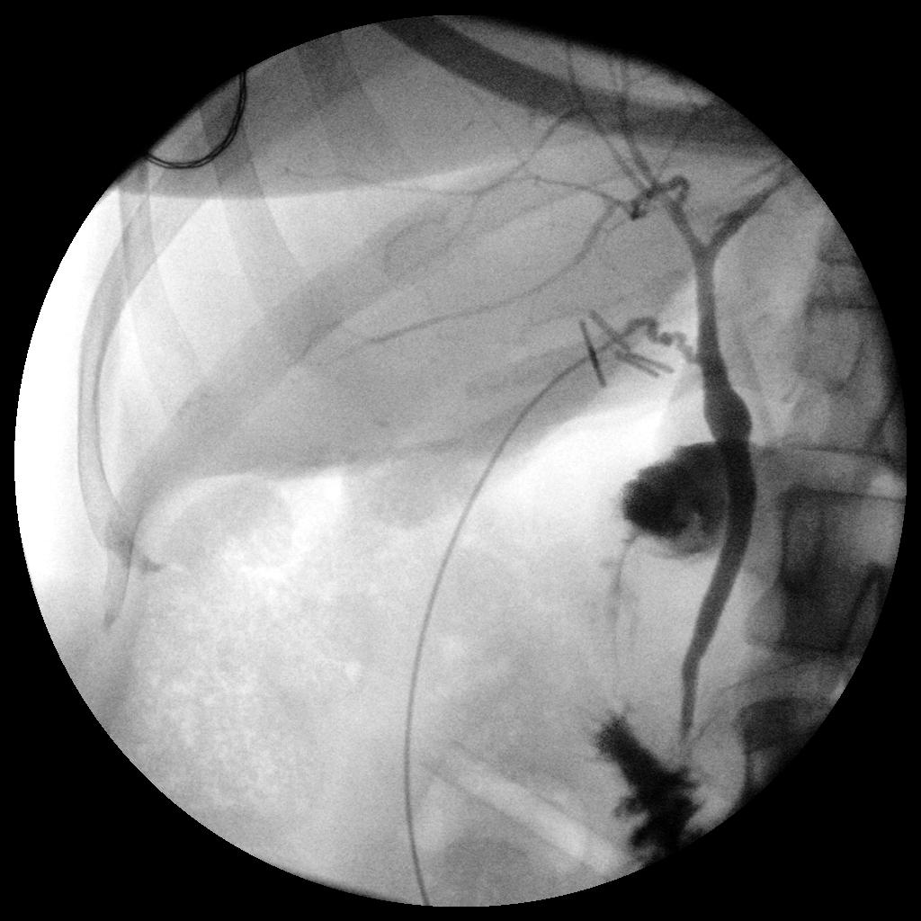
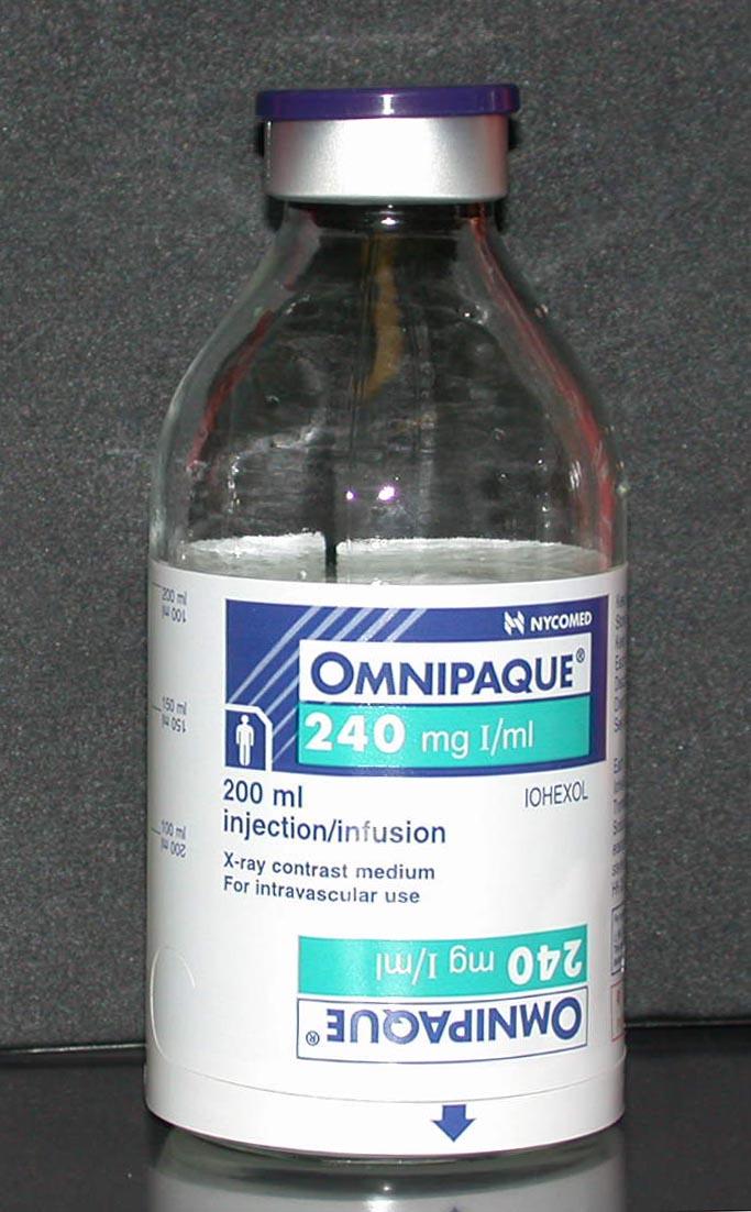
175 Patient Factors to Consider: Tissue Opacity Contrast Agents
176 Patient Factors to Consider: Body Habitus Hypersthenic Sthenic Hyposthenic Asthenic
177 The Contrast Unit
178 Subject Contrast: The magnitude of the signal difference in the remnant beam as a result of the different absorption characteristics of the tissues and structures making up that part. The difference in the thickness and atomic numbers of the structures that comprise the body part of interest. kvp is the primary controlling factor for subject contrast. This is the basis for optimum kvp.
179 Image (Radiographic) Contrast: The visible difference between any two selected brightness levels within a displayed image. It is determined by algorithms that are applied to raw data collected during image capture.
180 Image (Radiographic) Contrast: Grayscale The number of brightness levels or shades of gray visible on an image. Linked to the bit depth of the system which a reference to the total number of shades of gray available. How would noise affect grayscale?
181 Image (Radiographic) Contrast: Short Scale or High Contrast Major differences between shades of gray. Long Scale or Low Contrast Slight differences between shades of gray. kvp dictates the starting point for image contrast. All other factors that impact image contrast will cause it to increase or decrease from here.
182 Image (Radiographic) Contrast: High Contrast = Short Scale = Few Shades of Gray Low kvp Low Contrast = Long Scale = Many Shades of Gray High kvp


183 Image Contrast: Film/Screen Note the relationship between kvp and subject contrast. 50 kvp 100 kvp
184 Image Contrast: Konica CR 50 kvp 100 kvp CR algorithms work to maintain a similar scale of contrast even at different levels of kvp. A difference in contrast, albeit not as dramatic, does still exist.
185 Collimation vs. Contrast: Patient Image IR Tight Collimation
186 Collimation vs. Contrast: Patient Radiographic Image * No Collimation * IR
187 Collimation vs. Contrast: Patient Radiographic Image IR * No Collimation *
188 Collimation vs. Contrast: IR Radiographic Image * No Collimation *
189 Collimation vs. Contrast: IR Radiographic Image * * Bottom Line: No Lack Collimation of collimation adds unwanted scatter (noise) to the IR.

190 Collimation vs. Contrast: Konica CR 24 x 30 cm Collimation No Collimation S = 142 S = 103 The lower S value is the direct result of an increase in RE caused by a lack of collimation. Note the change in image contrast.
191 Added Filtration vs. the X-ray Emission Spectrum: Quantity or Intensity of X-ray Photons What happened to the average energy of the primary beam? What happened to the average energy of the primary beam? What will happen to contrast? 2.5 mm 3.5 mm X-ray Photon Energy (kev) 90

192 Filtration vs. Contrast: Konica CR 2.5 mm 3.5 mm 4.5 mm 5.5 mm
193 Filtration vs. Contrast: Konica CR 2.5 mm 5.5 mm The scale of contrast slowly decreases as Al filtration is increased. CR algorithms minimize the effect.
194 OID vs. Contrast: What happens to contrast? * Patient * Patient 1 OID 4 OID IR 10 mas at 75 kvp 20 mas at 75 kvp

195 OID vs. Contrast: Konica CR 4 OID 10 OID Note how the 10 OID image is slightly brighter indicating a shorter scale of image contrast.
196 Grids vs. Contrast: Patient * * What would happen to contrast if you changed to a larger grid? * * 8:1 GR IR
197 Grids vs. Contrast: Konica CR 6:1 Grid Ratio 15:1 Grid Radio S = 259 S = 257 Note the improvement in image contrast with the higher grid ratio.
198 Patient Factors to Consider: Body Habitus Additive vs. Destructive Diseases Casts
199 The Spatial Resolution Unit
200 Spatial Resolution (SR): i.e. Sharpness of Detail Sharpness of the structural edges recorded in the image. The ability to visualize sharp lines on a radiographic image. Measured in mm of unsharpness which indicates the level of image SR. Is a geometrically sharp image possible to achieve?
201 Motion: Single most detrimental factor Voluntary vs. Involuntary


202 Motion vs. SR: Voluntary Involuntary
203 Geometric Factors: 1. Focal Spot (FS) 2. Object-to-Image-receptor Distance (OID) 3. Source-to-Image-receptor Distance (SID) 4. Source-to-Object Distance (SOD)
204 Geometric Factors: Focal Spot Primary controlling factor for SR. Only variable that exclusively affects SR. Generally, techniques > 200 ma will require a large focal spot. Penumbra vs. Umbra
205 -- Focal Spot Size vs. SR: 0.6 mm FS 2.0 mm FS Patient IR


206 -- FS Size vs. SR: Konica CR Small FS Large FS
207 Geometric Factors: OID Of the geometric factors, this is the most critical factor to consider. What is the overall MOST critical factor to consider regarding SR?
208 -- OID vs. SR: 2.0 mm FS 2.0 mm FS 1 OID Patient 4 OID IR

209 OID vs. SR: Konica CR -- 1 OID 4 OID 8 OID Note how the SR decreases as the OID is increased.
210 -- SID vs. SR: 72 SID 40 SID Patient IR

211 SID vs. SR: Konica CR 40 SID 60 SID 72 SID CR algorithms work to maintain a similar level of SR. A difference in SR, albeit slight, does exist.
212 Geometric Unsharpness Formula: This formula is employed to determine how much unsharpness is created for a given set of technical factors FS x OID SOD
213 Example #1: How much geometric unsharpness is created when the following factors are employed for a lateral c-spine? 2 x mm FS OID SID = 0.32 mm of unsharpness The penumbra spreads across an area of 0.32 mm.
214 Example #2: How much geometric unsharpness is created when the following factors are employed for a PA chest? 1 x mm FS 2. 4 OID SID = 0.06 mm of unsharpness The penumbra spreads across an area of 0.06 mm. Which example produced the highest resolution?
215 SR vs. Visibility Properties: SR has no effect on Brightness and Contrast.
216 The Distortion Unit
217 Distortion: Can distortion ever be totally eliminated from the image? Consider the effect of placing a three dimensional object on a two dimensional image receptor (IR).

218
219

220 Size Distortion vs. OID: Konica CR 1 OID 4 OID 8 OID OID is the most critical factor affecting size distortion.


221 Size Distortion vs. SID: Konica CR 40 SID 60 SID 72 SID Size distortion will decrease as the SID in increased. How would you use SID to offset the magnification created by OID?
222 Methods to Calculate Magnification: 1. Magnification Factor or 2. Degree of Magnification Formula
223 Magnification Factor (MF): Image magnification can be assessed by calculating the ratio between SID and SOD. MF = SID/SOD Image Size = MF x Object Size
224 Example #1: What is the image size if the object size is 20, the SID is 40, and the OID is 4? MF = 40/36 MF = 1.11 (The image size will be 11% larger than the object size.) Image Size = 1.11 x 20 Image Size = 22.2
225 Degree of Magnification Formula: Image Width Object Width SID = SOD
226 Example #2: What is the image size if the object size is 20, the SID is 40, and the OID is 4? x 20 = x = 800 x = 22.2 Image Width
227 Percent of Magnification Formula: Image Width - Object Width Object Width 100
228 Example #3: Using the data gathered from Example #2, the object width was 20 and the image width was What is the percent increase in magnification that was produced for this exposure? x 100 = 11%100
229 Shape Distortion: Shape distortion may result in a misrepresentation of the anatomical areas of interest. Elongation vs. Foreshortening How to prevent shape distortion: Ensure that the body part is parallel to the IR. The CR must be perpendicular to the IR. Assure proper tube angulation. -Tube angles may be employed to desuperimpose pertinent anatomy.


230 Shape Distortion:


231 Shape Distortion:
232 Size Distortion vs. Shape of Distortion: Size distortion does not increase the level of shape distortion present in an image. However, size distortion will make shape distortion easier to recognize.
233 Distortion vs. Visibility Properties: Distortion has no effect on either image brightness or contrast.
234
Acquisition, Processing and Display
 Acquisition, Processing and Display Terri L. Fauber, R.T. (R)(M) Department of Radiation Sciences School of Allied Health Professions Virginia Commonwealth University Topics Image Characteristics Image
3/31/2011. Objectives. Emory University. Historical Development. Historical Development. Historical Development
 Teaching Radiographic Technique in a Digital Imaging Paradigm Objectives 1. Discuss the historical development of digital imaging. Dawn Couch Moore, M.M.Sc., RT(R) Assistant Professor and Director Emory
CR Basics and FAQ. Overview. Historical Perspective
 Page: 1 of 6 CR Basics and FAQ Overview Computed Radiography is a term used to describe a system that electronically records a radiographic image. Computed Radiographic systems use unique image receptors
10/26/2015. Study Harder
 This presentation is a professional collaboration of development time prepared by: Rex Christensen Terri Jurkiewicz and Diane Kawamura Study Harder CR detection is inefficient, inferior to film screen
10/3/2012. Study Harder
 This presentation is a professional collaboration of development time prepared by: Rex Christensen Terri Jurkiewicz and Diane Kawamura Study Harder CR detection is inefficient, inferior to film screen
Multiple Choice Identify the letter of the choice that best completes the statement or answers the question.
 RA110 test 3 Multiple Choice Identify the letter of the choice that best completes the statement or answers the question. 1. An object 35 cm in width is radiographed at 100 cm SID and at a 50 cm SOD. What
LECTURE 1 The Radiographic Image
 LECTURE 1 The Radiographic Image Prepared by:- KAMARUL AMIN ABDULLAH @ ABU BAKAR UiTM Faculty of Health Sciences Medical Imaging Department 11/23/2011 KAMARUL AMIN (C) 1 Lesson Objectives At the end of
COMPUTED RADIOGRAPHY CHAPTER 4 EFFECTIVE USE OF CR
 This presentation is a professional collaboration of development time prepared by: Rex Christensen Terri Jurkiewicz and Diane Kawamura New Technology https://www.youtube.com/watch?v=ptkzznazb 7U COMPUTED
Radiology Physics Lectures: Digital Radiography. Digital Radiography. D. J. Hall, Ph.D. x20893
 Digital Radiography D. J. Hall, Ph.D. x20893 djhall@ucsd.edu Background Common Digital Modalities Digital Chest Radiograph - 4096 x 4096 x 12 bit CT - 512 x 512 x 12 bit SPECT - 128 x 128 x 8 bit MRI -
RADIOGRAPHIC EXPOSURE
 RADIOGRAPHIC EXPOSURE Receptor Exposure Receptor Exposure the that interacts with the receptor. Computed Radiography ( ) requires a. Direct Digital Radiography (DR) requires a. Exposure Indicators Exposure
- KiloVoltage. Technique 101: Getting Back to Basics
 Why do I need to know technique? Technique 101: Getting Back to Basics Presented by: Thomas G. Sandridge, M.S., M.Ed., R.T.(R) Program Director Northwestern Memorial Hospital School of Radiography Chicago,
X-ray Imaging. PHYS Lecture. Carlos Vinhais. Departamento de Física Instituto Superior de Engenharia do Porto
 X-ray Imaging PHYS Lecture Carlos Vinhais Departamento de Física Instituto Superior de Engenharia do Porto cav@isep.ipp.pt Overview Projection Radiography Anode Angle Focal Spot Magnification Blurring
Amorphous Selenium Direct Radiography for Industrial Imaging
 DGZfP Proceedings BB 67-CD Paper 22 Computerized Tomography for Industrial Applications and Image Processing in Radiology March 15-17, 1999, Berlin, Germany Amorphous Selenium Direct Radiography for Industrial
SECTION I - CHAPTER 2 DIGITAL IMAGING PROCESSING CONCEPTS
 RADT 3463 - COMPUTERIZED IMAGING Section I: Chapter 2 RADT 3463 Computerized Imaging 1 SECTION I - CHAPTER 2 DIGITAL IMAGING PROCESSING CONCEPTS RADT 3463 COMPUTERIZED IMAGING Section I: Chapter 2 RADT
Digital Imaging Considerations Computed Radiography
 Digital Imaging Considerations Digital Radiography Computed Radiography o Cassette based Direct or Indirect Digital Radiography o Cassetteless Computed Radiography 1 CR Image Acquisition Most like conventional
SYLLABUS. TITLE: Equipment Operation I. DEPARTMENT: Radiologic Technology
 CODE: RADT 156 INSTITUTE: Health Science TITLE: Equipment Operation I DEPARTMENT: Radiologic Technology COURSE DESCRIPTION: This course covers the principles of equipment operation and maintenance of radiographic
Current technology in digital image production (CR/DR and other modalities) Jaroonroj Wongnil 25 Mar 2016
 Jaroonroj Wongnil 25 Mar 2016") Current technology in digital image production (CR/DR and other modalities) Jaroonroj Wongnil 25 Mar 2016 Current technology in digital image production (CR/DR and other modalities) 2/ Overview Digital
Current technology in digital image production (CR/DR and other modalities) Jaroonroj Wongnil 25 Mar 2016 Current technology in digital image production (CR/DR and other modalities) 2/ Overview Digital
RAD 150 RADIOLOGIC EXPOSURE TECHNIQUE II
 RAD 150 RADIOLOGIC EXPOSURE TECHNIQUE II APPROVED 12/O2/2011 EFFECTIVE SPRING 2013-14 Prefix & Number RAD 150 Course Title: Radiologic Exposure Technique II & Lab Purpose of this submission: New Change/Updated
STUDENT REVIEW QUESTION SET K CR/DR CONTENT AREA
 STUDENT REVIEW QUESTION SET K CR/DR CONTENT AREA RADT 2913 COMPREHENSIVE REVIEW 1 The CR cassette is backed by aluminum that: A. reflects x-rays B. absorbs x-rays C. captures the image D. transmits x-rays
Setting up digital imaging department!
 Outline Setting up digital imaging department! From screen/film to digital radiography PACS/Tele radiology Setting up digital department Digital Imaging Napapong Pongnapang, Ph.D. Department of Radiological
Essentials of Digital Imaging
 Essentials of Digital Imaging Module 1 Transcript 2016 ASRT. All rights reserved. Essentials of Digital Imaging Module 1 Fundamentals 1. ASRT Animation 2. Welcome Welcome to Essentials of Digital Imaging
Introduction. Chapter 16 Diagnostic Radiology. Primary radiological image. Primary radiological image
 Introduction Chapter 16 Diagnostic Radiology Radiation Dosimetry I Text: H.E Johns and J.R. Cunningham, The physics of radiology, 4 th ed. http://www.utoledo.edu/med/depts/radther In diagnostic radiology
Do you have any other questions? Please call us at (Toll Free) or , or
 or , or") INSTRUCTIONS Read the appropriate course/ textbook. This is an open book test. A score of 75% or higher is needed to receive CE credit. You will have a maximum of three attempts to pass this course. Please
INSTRUCTIONS Read the appropriate course/ textbook. This is an open book test. A score of 75% or higher is needed to receive CE credit. You will have a maximum of three attempts to pass this course. Please
Digital radiography: Practical advantages of Digital Radiography. Practical Advantages in image quality
 Digital radiography: Digital radiography is set to become the most common form of processing radiographic images in the next 10 years. This is due to a number of practical and image quality issues. Practical
2017 West Coast Educators Conference Orlando. Projection Geometry. 1. Review hierarchy of image qualities (amplified version):
:") Spatial Resolution in the Digital Age: NOTES Quinn B. Carroll, MEd, RT 2017 West Coast Educators Conference Orlando Projection Geometry 1. Review hierarchy of image qualities (amplified version): a. Maximum
Spatial Resolution in the Digital Age: NOTES Quinn B. Carroll, MEd, RT 2017 West Coast Educators Conference Orlando Projection Geometry 1. Review hierarchy of image qualities (amplified version): a. Maximum
Essentials of Digital Imaging
 Essentials of Digital Imaging Module 2 Transcript 2016 ASRT. All rights reserved. Essentials of Digital Imaging Module 2 Processing 1. ASRT Animation 2. Welcome Welcome to Essentials of Digital Imaging
SECTION I - CHAPTER 1 DIGITAL RADIOGRAPHY: AN OVERVIEW OF THE TEXT. Exam Content Specifications 8/22/2012 RADT 3463 COMPUTERIZED IMAGING
 RADT 3463 - COMPUTERIZED IMAGING Section I: Chapter 1 RADT 3463 Computerized Imaging 1 SECTION I - CHAPTER 1 DIGITAL RADIOGRAPHY: AN OVERVIEW OF THE TEXT RADT 3463 COMPUTERIZED IMAGING Section I: Chapter
1. Carlton, Richard R., and Arlene M. Adler. Principles of Radiographic Imaging: An Art and a Science, 5th edition (2013).
.") CODE: RADT 151 INSTITUTE: Health Science TITLE: Radiographic Exposure DEPARTMENT: Radiologic Technology COURSE DESCRIPTION: This course covers the principles of radiographic exposure selection and manipulation
CODE: RADT 151 INSTITUTE: Health Science TITLE: Radiographic Exposure DEPARTMENT: Radiologic Technology COURSE DESCRIPTION: This course covers the principles of radiographic exposure selection and manipulation
Small Animal Radiographic Techniques and Positioning COPYRIGHTED MATERIAL
 Small Animal Radiographic Techniques and Positioning COPYRIGHTED MATERIAL Section 1 Theory and Equipment 1 Introduction to Digital Imaging Small animal radiography has changed dramatically in the past
SPRINGFIELD TECHNICAL COMMUNITY COLLEGE ACADEMIC AFFAIRS
 SPRINGFIELD TECHNICAL COMMUNITY COLLEGE ACADEMIC AFFAIRS Course Number: RADG 112 Department: Radiography Course Title: Image Production & Eval. Semester: Spring Year: 1997 Objectives/ Unit One: Introduction
Mammography is a radiographic procedure specially designed for detecting breast pathology Approximately 1 woman in 8 will develop breast cancer over
 Mammography is a radiographic procedure specially designed for detecting breast pathology Approximately 1 woman in 8 will develop breast cancer over a lifetime Breast cancer screening programs rely on
Contrast. Contrast: the difference in density on adjacent areas of a radiograph or other image receptor. Subjective. Long Scale (Low Contrast)
") Contrast Contrast: the difference in density on adjacent areas of a radiograph or other image receptor. Subject Subjective Radiographic Long Scale (Low Contrast) Short Scale (High Contrast) Factors affecting
Contrast Contrast: the difference in density on adjacent areas of a radiograph or other image receptor. Subject Subjective Radiographic Long Scale (Low Contrast) Short Scale (High Contrast) Factors affecting
Unit thickness. Unit area. σ = NΔX = ΔI / I 0
 Unit thickness I 0 ΔI I σ = ΔI I 0 NΔX = ΔI / I 0 NΔX Unit area Δx Average probability of reaction with atom for the incident photons at unit area with the thickness of Delta-X Atom number at unit area
DELWORKS DR MEDICAL. take the next step
 DELWORKS DR MEDICAL take the next step DELWORKS MEDICAL DR If you are thinking of taking the next step to digital radiography, consider a DelWorks Medical DR Retrofit Package, the easy and affordable way
Digital Radiography : Flat Panel
 Digital Radiography : Flat Panel Flat panels performances & operation How does it work? - what is a sensor? - ideal sensor Flat panels limits and solutions - offset calibration - gain calibration - non
Mammography: Physics of Imaging
 Mammography: Physics of Imaging Robert G. Gould, Sc.D. Professor and Vice Chair Department of Radiology and Biomedical Imaging University of California San Francisco, California Mammographic Imaging: Uniqueness
Veterinary Science Preparatory Training for the Veterinary Assistant. Floron C. Faries, Jr., DVM, MS
 Veterinary Science Preparatory Training for the Veterinary Assistant Floron C. Faries, Jr., DVM, MS Radiology Floron C. Faries, Jr., DVM, MS Objectives Determine the appropriate machine settings for making
Outline ASRT Changes Impact on current curriculum Potential new courses WECM Changes Last update Resources and needs
 Change nd Annual Blinn College 2 nd Educator s Workshop For Radiologic Sciences July 28, 2007 Christi Carter, MSRS, RT(R) Outline ASRT Changes Impact on current curriculum Potential new courses WECM Changes
Digital Imaging started in the 1972 with Digital subtraction angiography Clinical digital imaging was employed from the 1980 ~ 37 years ago Amount of
 Digital Imaging started in the 1972 with Digital subtraction angiography Clinical digital imaging was employed from the 1980 ~ 37 years ago Amount of radiation to the population due to Medical Imaging
RADIOGRAPHY TERMS TO KNOW SELF STUDY DENTALELLE TUTORING
 RADIOGRAPHY TERMS TO KNOW SELF STUDY DENTALELLE TUTORING PLEASE NOTE You DO NOT need to study these for the board exam if this is why you bought our Radiography course, however if you come across any terms
4. Contrast is the. There must The function of contrast is to:. The types of contrast are.
 RADIOGRAPHIC VISIBILITY OF DETAIL STUDY QUESTIONS 1. What is visibility of detail? It is controlled by properties. What are the two factors that affect it? 2. What is sharpness of detail? It is controlled
BASICS OF FLUOROSCOPY
 Medical Physics Residents Training Program BASICS OF FLUOROSCOPY Dr. Khalid Alyousef, PhD Department of Medical Imaging King Abdulaziz Medical City- Riyadh Edison examining the hand of Clarence Dally with
Teaching Digital Radiography and Fluoroscopic Radiation Protection
 Teaching Digital Radiography and Fluoroscopic Radiation Protection WCEC 20 th Student Educator Radiographer Conference Dennis Bowman, RT(R), CRT (R)(F) Community Hospital of the Monterey Peninsula (CHOMP)
Beam-Restricting Devices
 Beam-Restricting Devices Three factors contribute to an increase in scatter radiation: Increased kvp Increased Field Size Increased Patient or Body Part Size. X-ray Interactions a some interact with the
X-ray Tube and Generator Basic principles and construction
 X-ray Tube and Generator Basic principles and construction Dr Slavik Tabakov - Production of X-rays and Patient Dose OBJECTIVES - X-ray tube construction - Anode - types, efficiency - Classical X-ray generator
X-RAY IMAGING EE 472 F2017. Prof. Yasser Mostafa Kadah
 X-RAY IMAGING EE 472 F2017 Prof. Yasser Mostafa Kadah www.k-space.org Recommended Textbook Stewart C. Bushong, Radiologic Science for Technologists: Physics, Biology, and Protection, 10 th ed., Mosby,
Digital radiography (DR) post processing techniques for pediatric radiology
 post processing techniques for pediatric radiology") Digital radiography (DR) post processing techniques for pediatric radiology St Jude Children s Research Hospital Samuel Brady, MS PhD DABR samuel.brady@stjude.org Purpose Review common issues and solutions
Digital radiography (DR) post processing techniques for pediatric radiology St Jude Children s Research Hospital Samuel Brady, MS PhD DABR samuel.brady@stjude.org Purpose Review common issues and solutions
Overview. Professor Roentgen was a Physicist!!! The Physics of Radiation Oncology X-ray Imaging
 The Physics of Radiation Oncology X-ray Imaging Charles E. Willis, Ph.D. DABR Associate Professor Department of Imaging Physics The University of Texas M.D. Anderson Cancer Center Houston, Texas Overview
Basis of Computed Radiography & PACS
 Basis of Computed Radiography & PACS Slavik Tabakov Computed Radiography (CR) refers to new types of X-ray detectors (i.e. replaces the X-ray Film) The CR output media is a digital image, which can be
10/15/2012 SECTION III - CHAPTER 6 DIGITAL FLUOROSCOPY RADT 3463 COMPUTERIZED IMAGING
 RADT 3463 - COMPUTERIZED IMAGING Section III: Chapter 6 RADT 3463 Computerized Imaging 1 SECTION III - CHAPTER 6 DIGITAL FLUOROSCOPY RADT 3463 COMPUTERIZED IMAGING Section III: Chapter 6 RADT 3463 Computerized
Digital Detector Array Image Quality for Various GOS Scintillators
 Digital Detector Array Image Quality for Various GOS Scintillators More info about this article: http://www.ndt.net/?id=22768 Brian S. White 1, Mark E. Shafer 2, William H. Russel 3, Eric Fallet 4, Jacques
9/10/2012. Computed Radiography Chapter 3 Physics and Technology. What is Computed Radiography?
 Computed Radiography Chapter 3 Physics and Technology This presentation is a professional collaboration of development time prepared by: Rex Christensen Terri Jurkiewicz and Diane Kawamura Today s Humor:
Visibility of Detail
 Visibility of Detail Radiographic Quality Quality radiographic images represents the, and information is for diagnosis. The of the anatomic structures and the accuracy of their ( ) determine the overall
COMPUTED RADIOGRAPHY (CR)
") COMPUTED RADIOGRAPHY (CR) Moving with the time Avi Avner BVSc BSc CVR DVDI MRCVS CR-Basics A five step process: 1. X-ray image received on phosphor plate 2. Image extracted from phosphor plate by Laser
COMPUTED RADIOGRAPHY (CR) Moving with the time Avi Avner BVSc BSc CVR DVDI MRCVS CR-Basics A five step process: 1. X-ray image received on phosphor plate 2. Image extracted from phosphor plate by Laser
Dental Radiography. One of the problems of dental radiography is having different dimensions than normal.
 The prototype receptor (the recording medium) most commonly used in dental radiography is the radiographic film. However, there are many other new more efficient receptors than the formed one that can
I. PERFORMANCE OF X-RAY PRODUCTION COMPONENTS FLUOROSCOPIC ACCEPTANCE TESTING: TEST PROCEDURES & PERFORMANCE CRITERIA
 FLUOROSCOPIC ACCEPTANCE TESTING: TEST PROCEDURES & PERFORMANCE CRITERIA EDWARD L. NICKOLOFF DEPARTMENT OF RADIOLOGY COLUMBIA UNIVERSITY NEW YORK, NY ACCEPTANCE TESTING GOALS PRIOR TO 1st CLINICAL USAGE
DIGITAL RADIOGRAPHY. Digital radiography is a film-less technology used to record radiographic images.
 DIGITAL RADIOGRAPHY Digital radiography is a film-less technology used to record radiographic images. 1 The purpose of digital imaging is to generate images that can be used in the diagnosis and assessment
Features and Weaknesses of Phantoms for CR/DR System Testing
 Physics testing of image detectors Parameters to test Features and Weaknesses of Phantoms for CR/DR System Testing Spatial resolution Contrast resolution Uniformity/geometric distortion Dose response/signal
Examination of Pipe Welds by Image Plate Based Computed Radiography System
 Examination of Pipe Welds by Image Plate Based Computed Radiography System Sanjoy Das, M.S.Rana, Benny Sebastian, D. Mukherjee and K.K. Abdulla Atomic Fuels Division Bhabha Atomic Research Centre Mumbai
SmartRAD. Advanced Digital Radiography System
 SmartRAD Advanced Digital Radiography System SmartRAD Expanding The Horizons Of Digital Radiography CMT introduces the SmartRAD Digital Radiography system, featuring an integrated flat panel digital detector
PERFORMANCE CHARACTERIZATION OF AMORPHOUS SILICON DIGITAL DETECTOR ARRAYS FOR GAMMA RADIOGRAPHY
 12 th A-PCNDT 2006 Asia-Pacific Conference on NDT, 5 th 10 th Nov 2006, Auckland, New Zealand PERFORMANCE CHARACTERIZATION OF AMORPHOUS SILICON DIGITAL DETECTOR ARRAYS FOR GAMMA RADIOGRAPHY Rajashekar
DIGITAL IMAGE PROCESSING IN X-RAY IMAGING
 DIGITAL IMAGE PROCESSING IN X-RAY IMAGING Shalini Kumari 1, Bachan Prasad 2,Aliya Nasim 3 Department of Electronics And Communication Engineering R.V.S College of Engineering & Technology, Jamshedpur,
Overview of Safety Code 35
 Common Quality Control Procedures for All s Quality Control Procedures Film All s Daily Quality Control Tests Equipment Warm-up (D1) According to manufacturers instructions Can include auto calibration(d1)
DISC QC/QA Program for Digital Imaging Systems using the DR Radchex Plus Meter
 DISC QC/QA Program for Digital Imaging Systems using the DR Radchex Plus Meter Revision Date: January 5th, 2017 www.disc-imaging.com Table of Contents Section A: Preliminary Setup Requirements... 4 Tools
radiography detector
 Clinical evaluation of a full field digital projection radiography detector Gary S. Shaber'1, Denny L. Leeb, Jeffrey Belib, Gregory Poweii1', Andrew D.A. Maidment'1 a Thomas Jefferson University Hospital,
Outline. Digital Radiography. Understanding Digital Modalities: Image Quality and Dose. Image Quality. Dose Control
 Understanding Digital Modalities: Image Quality and Dose S. Jeff Shepard, M.S. University of Texas M. D. Anderson Cancer Center Houston, Texas Special Acknowledgement: Stephen K. Thompson, M.S. William
Exposure System Selection
 Principles of Imaging Science II (RAD120) Exposure Systems Exposure System Selection Radiographic exposure is a very complex process Best technique systems manipulate one variable while holding others
JEFFERSON COLLEGE. Radiographic Exposures
 JEFFERSON COLLEGE COURSE SYLLABUS RAD140 Radiographic Exposures 3 Credit Hours Revised by: Janet E. Akers BS RT (R)(M) Date: September 30, 2013 Kenny Wilson, Director, Health Occupation Programs Dena McCaffrey,
X-rays in medical diagnostics
 X-rays in medical diagnostics S.Dolanski Babić 2017/18. History W.C.Röntgen (1845-1923) discovered a new type of radiation Nature, Jan. 23. 1896.; Science, Feb.14. 1896. X- rays: Induced the ionization
Conversion to Digital Radiography from Film Radiography
 Conversion to Digital Radiography from Film Radiography Steve Mango Worldwide Technical Manager Carestream NDT Rochester, NY Overview: Overview of digital Basic computed radiography (CR) Basic digital
Welcome to your selected S.T.A.R.S. developed continuing education home study!
 9.5 Dear GXMO/LSO/LSR participant, Welcome to your selected S.T.A.R.S. developed continuing education home study! In the spring of 2013, The Ohio Department of Health (ODH) approved ALL of them for GXMO
Digital Image Management: the Basics
 Digital Image Management: the Basics Napapong Pongnapang, Ph.D. Department of Radiological Technology Faculty of Medical Technology Mahidol University Outline From screen/film to digital radiography PACS/Tele
TECHNICAL DATA. GIOTTO IMAGE SDL/W is pre-arranged for Full Field Digital Biopsy examination with the patient in prone position.
 Ver. 01/06/07 TECHNICAL DATA GIOTTO IMAGE SDL/W LOW DOSE, FULL FIELD DIGITAL MAMMOGRAPHY UNIT USING AMORPHOUS SELENIUM (a-se) TECHNOLOGY DETECTOR (pre-arranged for stereotactic biopsy with the same digital
Moving from film to digital: A study of digital x-ray benefits, challenges and best practices
 Moving from film to digital: A study of digital x-ray benefits, challenges and best practices H.U. Pöhler 1 and N. D Ademo 2 DÜRR NDT GmbH & Co. KG, Höpfigheimer Straße 22, Bietigheim-Bissingen, 74321,
Chromatic X-Ray imaging with a fine pitch CdTe sensor coupled to a large area photon counting pixel ASIC
 Chromatic X-Ray imaging with a fine pitch CdTe sensor coupled to a large area photon counting pixel ASIC R. Bellazzini a,b, G. Spandre a*, A. Brez a, M. Minuti a, M. Pinchera a and P. Mozzo b a INFN Pisa
Comparison of computed radiography and filmõscreen combination using a contrast-detail phantom
 JOURNAL OF APPLIED CLINICAL MEDICAL PHYSICS, VOLUME 4, NUMBER 1, WINTER 2003 Comparison of computed radiography and filmõscreen combination using a contrast-detail phantom Z. F. Lu,* E. L. Nickoloff, J.
COMPUTED TOMOGRAPHY 1
 COMPUTED TOMOGRAPHY 1 Why CT? Conventional X ray picture of a chest 2 Introduction Why CT? In a normal X-ray picture, most soft tissue doesn't show up clearly. To focus in on organs, or to examine the
X-RAYS - NO UNAUTHORISED ENTRY
 Licencing of premises Premises Refer Guidelines A radiation warning sign and warning notice, X-RAYS - NO UNAUTHORISED ENTRY must be displayed at all entrances leading to the rooms where x-ray units are
AN ABSTRACT OF THE THESIS OF. W. Scott Helms for the degree of Master of Science in Radiation Health Physics
 AN ABSTRACT OF THE THESIS OF W. Scott Helms for the degree of Master of Science in Radiation Health Physics presented on November 24, 2014 Title: A Quantitative Comparison of Cardiovascular Imaging Systems
Seminar 8. Radiology S8 1
 Seminar 8 Radiology Medical imaging. X-ray image formation. Energizing and controlling the X-ray tube. Image detectors. The acquisition of analog and digital images. Digital image processing. Selected
PD233: Design of Biomedical Devices and Systems
 PD233: Design of Biomedical Devices and Systems (Lecture-8 Medical Imaging Systems) (Imaging Systems Basics, X-ray and CT) Dr. Manish Arora CPDM, IISc Course Website: http://cpdm.iisc.ac.in/utsaah/courses/
Exposure Indices and Target Values in Radiography: What Are They and How Can You Use Them?
 Exposure Indices and Target Values in Radiography: What Are They and How Can You Use Them? Definition and Validation of Exposure Indices Ingrid Reiser, PhD DABR Department of Radiology University of Chicago
A Practical Overview of the Clinical and Operational Impact of Computed Radiography(CR) Implementations. Shirley Weddle, RT(R)(M), CIIP, BBA
 Implementations. Shirley Weddle, RT(R)(M), CIIP, BBA") A Practical Overview of the Clinical and Operational Impact of Computed Radiography(CR) Implementations Shirley Weddle, RT(R)(M), CIIP, BBA OBJECTIVES Define Computed Radiography (CR) Discuss CR vendor
A Practical Overview of the Clinical and Operational Impact of Computed Radiography(CR) Implementations Shirley Weddle, RT(R)(M), CIIP, BBA OBJECTIVES Define Computed Radiography (CR) Discuss CR vendor
GE Healthcare. Senographe 2000D Full-field digital mammography system
 GE Healthcare Senographe 2000D Full-field digital mammography system Digital has arrived. The Senographe 2000D Full-Field Digital Mammography (FFDM) system gives you a unique competitive advantage. That
Y11-DR Digital Radiography (DR) Image Quality
 Image Quality") Y11-DR Digital Radiography (DR) Image Quality Image quality is stressed for all systems in Safety Code 35. In the relevant sections Health Canada s advice is the manufacturer s recommended test procedures
Y11-DR Digital Radiography (DR) Image Quality Image quality is stressed for all systems in Safety Code 35. In the relevant sections Health Canada s advice is the manufacturer s recommended test procedures
The Evaluation of Collimator Alignment of Diagnostic X-ray Tube Using Computed Radiography System
 The Evaluation of Collimator Alignment of Diagnostic X-ray Tube Using Computed Radiography System The Evaluation of Collimator Alignment of Diagnostic X-ray Tube Using Computed Radiography System Manus
Investigation of the line-pair pattern method for evaluating mammographic focal spot performance
 Investigation of the line-pair pattern method for evaluating mammographic focal spot performance Mitchell M. Goodsitt, a) Heang-Ping Chan, and Bob Liu Department of Radiology, University of Michigan, Ann
X-RAY FLUOROSCOPY IMAGING SYSTEMS. Dr Slavik Tabakov. Luminescence: Dept. Medical Eng. & Physics King s College London
 X-RAY FLUOROSCOPY IMAGING SYSTEMS Dr Slavik Tabakov OBJECTIVES - Image Intensifier construction - Input window - Accelerating and focusing electrodes - Output window - Conversion factor - II characteristics
of sufficient quality and quantity
 of sufficient quality and quantity The patient s body attenuates the beam as it passes though the body More energy is deposited in organs located near the entry of the beam than near the exit of the beam
Film Replacement in Radiographic Weld Inspection The New ISO Standard
 BAM Berlin Film Replacement in Radiographic Weld Inspection The New ISO Standard 17636-2 Uwe Ewert, Uwe Zscherpel, Mirko Jechow Requests and information to: uwez@bam.de 1 Outline - The 3 essential parameters
Acceptance Testing of a Digital Breast Tomosynthesis Unit
 Acceptance Testing of a Digital Breast Tomosynthesis Unit 2012 AAPM Spring Clinical Meeting Jessica Clements, M.S., DABR Objectives Review of technology and clinical advantages Acceptance Testing Procedures
Get more from your images with Symphony Image Processing
 DIRECT RADIOGRAPHY The user-friendly DelWorks image acquisition and processing software possesses a wide range of tools for a variety of image manipulations. Its user interface simplifies every step of
Dose Reduction and Image Preservation After the Introduction of a 0.1 mm Cu Filter into the LODOX Statscan unit above 110 kvp
 Dose Reduction and Image Preservation After the Introduction of a into the LODOX Statscan unit above 110 kvp Abstract: CJ Trauernicht 1, C Rall 1, T Perks 2, G Maree 1, E Hering 1, S Steiner 3 1) Division
X-ray Tube and Generator Basic principles and construction
 X-ray Tube and Generator Basic principles and construction Dr Slavik Tabakov - Production of X-rays OBJECTIVES - X-ray tube construction - Anode - types, efficiency - X-ray tube working characteristics
DIGITAL IMAGING Recognise the importance of quality assurance
 DIGITAL IMAGING Recognise the importance of quality assurance There are two types of digital image receptor both of which capture a two dimensional image of the three dimensional patient. These are Computed
NOTES Teaching Digital Processing and Display Quinn B Carroll, MEd, RT WCEC Conference, 2015
 NOTES Teaching Digital Processing and Display Quinn B Carroll, MEd, RT WCEC Conference, 2015 1. Teaching Pitfalls: Accuracy Vs. Simplicity 2. Teaching Decisions: 1. Is it relevant? (Not: Is it in my comfort
X-ray detectors in healthcare and their applications
 X-ray detectors in healthcare and their applications Pixel 2012, Inawashiro September 4th, 2012 Martin Spahn, PhD Clinical applications of X-ray imaging Current X-ray detector technology (case study radiography
X-rays. X-rays are produced when electrons are accelerated and collide with a target. X-rays are sometimes characterized by the generating voltage
 X-rays Ouch! 1 X-rays X-rays are produced when electrons are accelerated and collide with a target Bremsstrahlung x-rays Characteristic x-rays X-rays are sometimes characterized by the generating voltage
7/24/2014. Image Quality for the Radiation Oncology Physicist: Review of the Fundamentals and Implementation. Disclosures. Outline
 Image Quality for the Radiation Oncology Physicist: Review of the Fundamentals and Implementation Image Quality Review I: Basics and Image Quality TH-A-16A-1 Thursday 7:30AM - 9:30AM Room: 16A J. Anthony
Essentials of Digital Imaging
 Essentials of Digital Imaging Module 7 Transcript 2016 ASRT. All rights reserved. Essentials of Digital Imaging Module 7 Quality 1. ASRT Animation 2. Welcome Welcome to the Essentials of Digital Imaging: