Chapter 28: Abrasive Machining Processes. DeGarmo s Materials and Processes in Manufacturing
|
|
|
- Darleen Morris
- 5 years ago
- Views:
Transcription
1 Chapter 28: Abrasive Machining Processes DeGarmo s Materials and Processes in Manufacturing
2 28.1 Introduction Abrasive machining is the process of using abrasive grit to remove material at high cutting speed and shallow depths of penetration. The abrasive particles may be (1) free; (2) mounted in resin on a belt (called coated product); or, most commonly (3) close packed into wheels or stones, with abrasive grits held together by bonding material (called bonded product or a grinding wheel).
3 Typical Grinding Wheel FIGURE 28-1 Schematic of surface grinding, showing infeed and cross feed motions along with cutting speeds VS, and workpiece velocity VW.

4 Abrasive Processes
5 Grinding Parameters
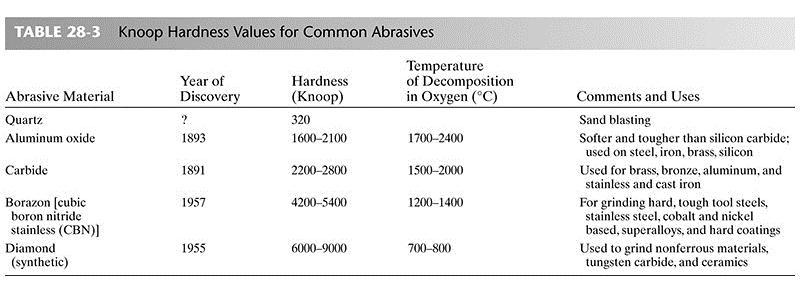
6 28.2 Abrasives An abrasive is a hard material that can cut or abrade other substances Natural abrasives sandstone was used by ancient peoples to sharpen tools and weapons. Emery, a mixture of alumina (Al2O3) and magnetite (Fe3O4), is another natural abrasive still in use today Corundum (natural Al2O3) and diamonds are other naturally occurring abrasive materials. Today, the only natural abrasives that have commercial importance are quartz, sand, garnets, and diamonds.
7 Artificial abrasives date from 1891, when silicon carbide (SiC) was first produced. Other artifical abrasives used today include: Aluminum oxide (Al2O3) is the most widely used artificial abrasive. Diamonds are the hardest of all materials. Those that are used for abrasives are either natural, off-color stones that are not suitable for gems, or small, synthetic stones that are produced specifically for abrasive purposes. Cubic boron nitride (CBN) is extremely hard. It is the second-hardest substance created by nature or manufactured and is often referred to, along with diamonds, as a superabrasive.
8

9 FIGURE 28-2 Loose abrasive grains at high magnification, showing their irregular, sharp cutting edges. (Courtesy of Norton Company.)
10 Sizing of Abrasives Abrasives are sized to control material removal rate and resultant surface finish. A screen size number refers to the number of openings per square inch at a give wire size. Grit numbers have been converted to millimeter in micrometer sizes for more standardization. Regardless of grain size only 2-5% of a individual grain is exposed due to bonding
, the smaller the grain size.")
11 Sizing Screens FIGURE 28-3 Typical screens for sifting abrasives into sizes. The larger the screen number (of opening per linear inch), the smaller the grain size. (Courtesy of Carborundum Company.)
12 Surface Finish versus Grit Size FIGURE 28-4 MRR and surface finish versus grit size.
13 Grit Geometry Abrasive grains are not uniform in shape and are randomly distributed across the surface. Not all grains cut at the optimum angle but due to distribution, the grinding surface is designed to the average distribution. Chips either cut, plow or rub on the surface. Grit density determines the chip loading. As grit material abrade, fracture, or are dislodged, new grit material is exposed, creating a continuous removal rate.

14 Rake Angle FIGURE 28-5 The rake angle of abrasive particles can be positive, zero, or negative.

15 Grit Distribution FIGURE 28-6 The cavities or voids between the grains must be large enough to hold all the chips during the cut.

16 Grit Orientation FIGURE 28-7 The grits interact with the surface in three ways: cutting, plowing, and rubbing.
, a prow formation (P), and a groove (G) where the fractured portion was pushed farther across the")
17 Plowing FIGURE 28-8 SEM micrograph of a ground steel surface showing a plowed track (T) in the middle and a machined track (M) above. The grit fractured, leaving a portion of the grit in the surface (X), a prow formation (P), and a groove (G) where the fractured portion was pushed farther across the surface. The area marked (O) is an oil deposit.
 of the chips have the typical shearfront-lamella structure while the bottoms (B) are smooth where they")
18 Grinding Chips FIGURE 28-9 SEM micrograph of stainless steel chips from a grinding process. The tops (T) of the chips have the typical shearfront-lamella structure while the bottoms (B) are smooth where they slide over the grit 4800.
19 28.3 Grinding Wheel Structure and Grade Grinding is where the abrasive is bonded into a wheel, and is the most common abrasive method. The grade of a wheel is a function of the rate of fracture of the abrasive from the surface. A wheel is graded as hard if the dislodging force is high and soft if the abrasive dislodging force is small
20 G Ratio The G ratio is defined as the ratio of workpiece material removed to grinding wheel material removed. Ratios of 20:1 to 80:1 are common. Wheel performance is influenced by: 1. The mean force required to dislodge a grain from the surface (the grade of the wheel) 2. The cavity size and distribution of the porosity (the structure) 3. The mean spacing of active grains in the wheel surface (grain size and structure) 4. The properties of the grain (hardness, attrition, and friability) 5. The geometry of the cutting edges of the grains (rake angles and cutting-edge radius compared to depth of cut) 6. The process parameters (speeds, feeds, cutting fluids) and type of grinding (surface, or cylindrical)
 The structure of a grinding wheel depends on the spacing of the grits.")
21 Wheel Structure FIGURE Meaning of terms structure and grade for grinding wheels. (a) The structure of a grinding wheel depends on the spacing of the grits. (b) The grade of a grinding wheel depends on the amount of bonding agent (posts) holding abrasive grains in the wheel.
22 Bonding Materials Bonding materials in common use are the following: 1. Vitrified bonds are composed of clays and other ceramic substances. 2. Resinoid, or phenolic resins are used. 3. Silicate wheels use silicate of soda (waterglass) as the bond material. 4. Shellac-bonded wheels are made by mixing the abrasive grains with shellac in a heated mixture 5. Rubber bonding is used to produce wheels that can operate at high speeds but must have a considerable degree of flexibility. 6. Superabrasive wheels are either electroplated or a thin segmented drum of vitrified CBN surrounds on a steel core.
23 Grinding Force Very rapid material rates, similar in speed to milling, is called abrasive machining. Abrasive machining can produce high localized stress and heat within the material resulting in abusive grinding Figure shows the stress differences between abusive, conventional and low stress grinding.
24 Wheel Stress Distribution FIGURE Typical residual stress distributions produced by surface grinding with different grinding conditions for abusive, conventional, and low-stress grinding. Material is 4340 steel. (From M. Field and W. P. Kosher, Surface Integrity in Grinding, in New Developments in Grinding, Carnegie-Mellon University Press, Pittsburgh, 1972, p. 666.)
25 Grinding Wheel Truing and Dressing Grinding wheels lose their geomtry with use, truing restores the original shape. Truing grinds a small amount of material to expose new grinding media, and new cutting edges on worn glazed grains. As grinding wheels are used then tend to become loaded with lodged metal chips in the cavities. Dressing is used to remove the lodged metal chips.
26 Truing Methods FIGURE Truing methods for restoring grinding geometry include nibs, rolls, disks, cups, and blocks.
27 Dressing FIGURE Schematic arrangement of stick dressing versus truing.
 doing plunge cut grinding on a cylinder held between")
28 Crush Dressing FIGURE Continuous crush roll dressing and truing of a grinding wheel (form truing and dressing throughout the process rather than between cycles) doing plunge cut grinding on a cylinder held between centers.
29 28.4 Grinding Wheel Identification FIGURE Standard marking systems for grinding wheels (ANSI standard B ).
30 Grinding Wheel Identification FIGURE Standard marking systems for grinding wheels (ANSI standard B ).
31 Wheel Shapes FIGURE Standard grinding wheel shapes commonly used. (Courtesy of Carborundum Company.)
32 Standard Faces FIGURE Standard face contours for straight grinding wheels. (Courtesy of Carborundum Company.)
33 Grinding Operations The major use categories are the following: 1. Cutting off: for slicing and slotting parts; use thin wheel, organic bond 2. Cylindrical between centers: grinding outside diameters of cylindrical workpieces 3. Cylindrical, centerless: grinding outside diameters with work rotated by regulating wheel 4. Internal cylindrical: grinding bores and large holes 5. Snagging:removing large amounts of metal without regard to surface finish or tolerances 6. Surface grinding: grinding flat workpieces 7. Tool grinding: for grinding cutting edges on tools such as drills, milling cutters, taps, reamers, and single-point high-speed-steel tools 8. Offhand grinding: work or the grinding tool is handheld
34 Operational Parameters Grinding Wheel Balance Wheel balance in needed to ensure that vibration will not cause the wheel to break Truing will often return a wheel to balance Grinding Safety Wheel accident the result of wheel being turn at too high of rpm Abuse of wheels, such as dropping cause wheel weakness Improver use, such a grinding on the side Improper use of eye sheilds Use of Cutting Fluids Fluids wash away chips Cool the workpiece

35 Coolant Delivery FIGURE Coolant delivery system for optimum CBN grinding. (Source: Production Grinding with CBN, M. P. Hitchiner, CBN Grinding Systems Manager, Universal Beck, Romulus, MI, Machining Technology, Vol. 2, No. 2, 1991.) improper
36 28.5 Grinding Machines Grinding Machines are classified according to the surface they produce. Table 28-4 list the types of grinding machines Grinding is done in three ways Infeed moving the wheel across the surface Plunge-cut the material is rotates as the wheel moves radially into the surface. Creep Feed Grinding the material is feed past the wheel.
37 Types of Grinding Machines
38 Horizontal Spindle FIGURE Horizontal spindle surface grinder, with insets showing movements of wheelhead.
39 Conventional Grinding FIGURE Conventional grinding contrasted to creep feed grinding. Note that crush roll dressing is used here; see Figure
40 Grinding Comparison
41 Cylindrical Grinding Cylindrical grinding is used to produce external cylindrical surfaces In cylindrical grinding the workpiece is mounted and rotated on a longitudinal axis, the grinding wheel rotate in the same axis, but in opposite directions. With long workpieces, the workpiece typically is moved relative to the wheel. With smaller high production parts, a chuck-type external grinder is used, and the wheel moves relative to the workpiece.
42 Center Grinding FIGURE Cylindrical grinding between centers.
43 Centerless Grinding In centerless grinding the workpiece can be ground internally or externally without requiring the material to be mounted in a center or chuck. The workpiece rests between two wheels, one providing the grinding and the other providing regulation of the grinding speed.
44 Centerless Grinding FIGURE Centerless grinding showing the relationship among the grinding wheel, the regulating wheel, and the workpiece in centerless method. (Courtesy of Carborundum Company.)
45 Advantages of Centerless Grinding Centerless grinding has several important advantages: 1. It is very rapid; infeed centerless grinding is almost continuous. 2. Very little skill is required of the operator. 3. It can often be made automatic (single-cycle automatic). 4. Where the cutting occurs, the work is fully supported by the work rest and the regulating wheel.this permits heavy cuts to be made. 5. Because there is no distortion of the workpiece, accurate size control is easily achieved. 6. Large grinding wheels can be used, thereby minimizing wheel wear.
46 Disadvantages of Centerless Grinding The major disadvantages are as follows: 1. Special machines are required that can do no other type of work. 2. The work must be round no flats, such as keyways, can be present. 3. Its use on work having more than one diameter or on curved parts is limited. 4. In grinding tubes, there is no guarantee that the OD and Internal Diameter (ID) are concentric.
47 Surface Grinding Surface Grinding Machines are used to produce flat surfaces. The four basic types are: 1. Horizontal spindle and reciprocating table 2. Vertical spindle and reciprocating table 3. Horizontal spindle and rotary table 4. Vertical spindle and rotary table
 and (d) both horizontal- and verticalspindle machines can have rotary tables.")
48 Surface Grinding Machines FIGURE Surface B grinding: (a) horizontal surface grinding and reciprocating table; (b) vertical spindle with reciprocating table; (c) and (d) both horizontal- and verticalspindle machines can have rotary tables. (Courtesy of Carborundum Company.)
49 Tool Grinding Mills cutters, reams, and single point tools require sophisticated grinding provided by a tool grinder that differs from a universal cylindrical center-type grinder by: 1. The headstock is not motorized. 2. The headstock can be swiveled about a horizontal as well as a vertical axis. 3. The wheelhead can be raised and lowered and can be swiveled through at 360 rotation about a vertical axis. 4. All table motions are manual. No power feeds being provided.
 Singlepoint tool is held in a device that permits all possible angles to be ground. (b) Edges of a large hand reamer are being ground.")
50 Tool Grinding Machine FIGURE Three typical setups for grinding single- and multiple-edge tools on a universal tool and cutter grinder. (a) Singlepoint tool is held in a device that permits all possible angles to be ground. (b) Edges of a large hand reamer are being ground. (c) Milling cutter is sharpened with a cupped grinding wheel.
51 Other Grinding Tools Mounted Wheels and Points are small tools used in finishing work. Typically mounted on portable high speed chucks RPM s to 100,000 depending upon diamter Coated Abrasives Come in disk, sheets, rolls, belts, etc. Consist of abrasives glued to a cloth or paper backing Designed to be easily replaced when dull or the loaded

52 Mounted Wheels and Points for High Speed Hand Tools FIGURE Examples of mounted abrasive wheels and points. (Courtesy of Norton Company.)

53 Coated Abrasives FIGURE Belt composition for coated abrasives (top).

54 Coated Abrasive Machines FIGURE Platen grinder and examples of belts and disks for abrasive machining.
55 28.6 Honing Honing is used to produce is used to remove small amounts of material to produce an exacting size and surface finish. Most common application is to produce precise surface finish in engine cylinder walls and hydraulic cylinder fabrication Rotation and axial oscillation is used to produce the desired surface throughout the entire length of the hole. Honing is done with cutting fluids and honing stones, special grinding stones with grit with the addition of additives to modify the cutting
56 Cylindrical Honing FIGURE Schematic of honing head showing the manner in which the stones are held. The rotary and oscillatory motions combine to produce a crosshatched lay pattern. Typical values for Vc and Ps are given below.
57 28.7 Superfinishing Superfinishing is a variation of honing that is typically used on flat surfaces. The process is: 1. Very light, controlled pressure, 10 to 40 psi 2. Rapid (over 400 cycles per minute), short strokes less than 1/4 in. 3. Stroke paths controlled so that a single grit never traverses the same path twice 4. Copious amounts of low-viscosity lubricantcoolant flooded over the work surface

58 Superfinishing FIGURE In superfinishing and honing, a film of lubricant is established between the work and the abrasive stone as the work becomes smoother.
59 Lapping Lapping is the process where the abrasive media is charged (embedded) into a softer media called lap Lap material range from various types of cloth, or soft metal such as copper. The embedded particles do the cutting not the lap The abrasive is carried away by the lapping oil, or coolant, and needs frequent replacement. Lapping removes material very slowly and is typically used to remove machining and grinding marks, producing a polished surface.
60 28.8 Free Abrasives There are various forms of free abrasive machining Ultrasonic Abrasives are mixed in a slurry, ultrasonic transducers provide the mechanical agitation to remove the material Waterjet cutting (WJC) Water at 60,000 psi and 3000 ft/s erode the material Abrasive Waterjet Cutting (AWC) Abrasives are added to a Waterjet to improve the efficiency Abrasive Jet Cutting (AJC) Abrasives are mixed in a high velocity air stream at 1000 ft/s
61 Ultrasonic Machining FIGURE Sinking a hole in a workpiece with an ultrasonically vibrating tool driving an abrasive slurry.

62 Water Jet Machining FIGURE Schematic diagram of hydrodynamic jet machining. The intensifier elevates the fluid to the desired nozzle pressure while the accumulator smoothes out the pulses in the fluid jet.
63 Water Jet Cutting Head FIGURE Schematic of an abrasive waterjet machining nozzle is shown on the right.
64

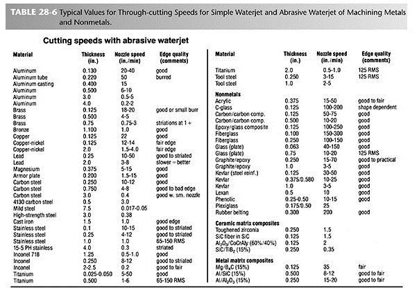
65 Cutting Speeds for a Waterjet
Chapter 26 Abrasive Machining Processes. Materials Processing ABRASIVE MACHINING 10/11/2014. MET Manufacturing Processes
 MET 33800 Manufacturing Processes Chapter 26 Abrasive Machining Processes Before you begin: Turn on the sound on your computer. There is audio to accompany this presentation. Materials Processing Chapters
MANUFACTURING TECHNOLOGY
 MANUFACTURING TECHNOLOGY UNIT IV SURFACE FINISHING PROCESS Grinding Grinding is the most common form of abrasive machining. It is a material cutting process which engages an abrasive tool whose cutting
Grinding. Vipin K Sharma
 Grinding Grinding It is a material cutting process which engages an abrasive tool(in the form of a wheel) whose cutting elements are grains of abrasive material known as grit. These grits are characterized
INTRODUCTION TO GRINDING PROCESS
 GRINDING PART 2 Grinding Grinding is a material removal process accomplished by abrasive particles that are contained in a bonded grinding wheel rotating at very high surface speeds. The rotating grinding
Abrasive Machining and Finishing Operations
 Abrasive Machining and Finishing Operations Bonded Abrasives Used in Abrasive-Machining Processes Figure 25.1 A variety of bonded abrasives used in abrasivemachining processes. Source: Courtesy of Norton
Abrasive Machining Processes. N. Sinha, Mechanical Engineering Department, IIT Kanpur
 Abrasive Machining Processes N. Sinha, Mechanical Engineering Department, IIT Kanpur Introduction Abrasive machining involves material removal by the action of hard, abrasive particles. The use of abrasives
GRINDING. quakerchem.com
 OVERVIEW Metal removal fluids (MRF) are used for both machining and grinding applications. As was discussed in the basic training, both applications are similar in that there is an interface between the
Finishing Process. By Prof.A.Chandrashekhar
 Finishing Process By Prof.A.Chandrashekhar Introduction Finishing process are different from other manufacturing processes. The distinction between the finishing processes and other manufacturing processes
MILLING and GRINDING MACHINES Machine Tools
 ELEMENTS OF MECHANICAL ENGINEERING PART B UNIT VI MILLING and GRINDING MACHINES Machine Tools 1 Objectives: 1.1 To understand the Principle of working of Milling, Horizontal & Vertical Milling. 1.2 Classification/Types
7 ABRASIVE AND NON-TRADITIONAL
 7 ABRASIVE AND NON-TRADITIONAL PROCESSES CHAPTER CONTENTS 7.1 Grinding Definitions Cutting conditions in grinding Wheel wear Surface finish and effects of cutting temperature Grinding wheel Grinding operations
Roughing vs. finishing
 Finishing methods Roughing vs. finishing Roughing removing material as fast as possible, without special demands on surface and low demand on precision high Q, high IT, high Ra Finishing making final surface
ABRASIVE PROCESSES AND BROACHING
 UNIT 4 www.studentsfocus.com ABRASIVE PROCESSES AND BROACHING 1. What are the types of surfaces that could de produced using plain cylindrical grinders? Plain cylindrical parts, cylindrical parts, cylinders,
SURFACE FINISHING GRINDING MACHINES
 SURFACE FINISHING GRINDING MACHINES Introduction :- Grinding is a metal cutting operation which is performed by means of a rotating abrasive wheel acts as a cutting tool. Material removal is in the form
Materials Removal Processes (Machining)
") Chapter Six Materials Removal Processes (Machining) 6.1 Theory of Material Removal Processes 6.1.1 Machining Definition Machining is a manufacturing process in which a cutting tool is used to remove excess
Chapter Six Materials Removal Processes (Machining) 6.1 Theory of Material Removal Processes 6.1.1 Machining Definition Machining is a manufacturing process in which a cutting tool is used to remove excess
Elimination of Honing Stick Mark in Rack Tube B.Parthiban1 1, N.Arul Kumar 2, K.Gowtham Kumar 3, P.Karthic 4, R.Logesh Kumar 5
 Elimination of Honing Stick Mark in Rack Tube B.Parthiban1 1, N.Arul Kumar 2, K.Gowtham Kumar 3, P.Karthic 4, R.Logesh Kumar 5 Assistant Professor, Dept. of Mechanical Engineering, Jay Shriram Group of
A TRADITION OF QUALITY SINCE 1966 DIAMOND AND CBN WHEELS
 A TRADITION OF QUALITY SINCE 1966 DIAMOND AND CBN WHEELS POLTAVA DIAMOND TOOLS has been manufacturing top-quality diamond tools for the machine building, glass, electronic and woodworking industries since
MACHINE TOOLS GRINDING MACHINE TOOLS
 MACHINE TOOLS GRINDING MACHINE TOOLS GRINDING MACHINE TOOLS Grinding in generally considered a finishing operation. It removes metal comparatively in smaller volume. The material is removed in the form
NON-TRADITIONAL MACHINING PROCESSES ULTRASONIC, ELECTRO-DISCHARGE MACHINING (EDM), ELECTRO-CHEMICAL MACHINING (ECM)
, ELECTRO-CHEMICAL MACHINING (ECM)") NON-TRADITIONAL MACHINING PROCESSES ULTRASONIC, ELECTRO-DISCHARGE MACHINING (EDM), ELECTRO-CHEMICAL MACHINING (ECM) A machining process is called non-traditional if its material removal mechanism is basically
NON-TRADITIONAL MACHINING PROCESSES ULTRASONIC, ELECTRO-DISCHARGE MACHINING (EDM), ELECTRO-CHEMICAL MACHINING (ECM) A machining process is called non-traditional if its material removal mechanism is basically
Metal Cutting (Machining)
") Metal Cutting (Machining) Metal cutting, commonly called machining, is the removal of unwanted portions from a block of material in the form of chips so as to obtain a finished product of desired size,
Metal Cutting (Machining) Metal cutting, commonly called machining, is the removal of unwanted portions from a block of material in the form of chips so as to obtain a finished product of desired size,
 VALLIAMMAI ENGINEERING COLLEGE DEPARTMENT OF MECHANICAL ENGINEERING QUESTION BANK ME6402 MANUFACTURING TECHNOLOGY II UNIT-I PART A 1. List the various metal removal processes? (BT1) 2. Explain how chip
A Pictorial Odyssey. Grinding: An examination of the grinding process through the lens of an electron microscope. By Dr.
 Grinding: A Pictorial Odyssey A FEBRUARY 2009 / VOLUME 61 / ISSUE 2 By Dr. Jeffrey Badger An examination of the grinding process through the lens of an electron microscope. picture is worth a thousand
Trade of Metal Fabrication. Module 1: Basic Fabrication Unit 12: Abrasive Grinding and Cutting Phase 2
 Trade of Metal Fabrication Module 1: Basic Fabrication Unit 12: Abrasive Grinding and Cutting Phase 2 Table of Contents List of Figures... 4 List of Tables... 5 Document Release History... 6 Module 1
HONING OPERATIONAL INFORMATION & TROUBLE SHOOTING DATA
 3225 Ave E East, Arlington TX 76011 www.abrasivehones.com 1-800-966-7574 - Fax 817-695-1001 Sales@SSUNL.com HONING OPERATIONAL INFORMATION & TROUBLE SHOOTING DATA Page 1: Page 2: Page 3: Page 4: Page 5:
Turning and Lathe Basics
 Training Objectives After watching the video and reviewing this printed material, the viewer will gain knowledge and understanding of lathe principles and be able to identify the basic tools and techniques
Product Range. Solutions for Industry.
 Product Range Solutions for Industry www.master-abrasives.co.uk Introduction Master Abrasives has a hard and long earned reputation in the UK abrasives market for providing solutions with high quality
Sharpening Twist Drills. Relief Grinding of the Tool Flanks.
 TOOL WEAR 933 Tool Wear Metal cutting tools wear constantly when they are being used. A normal amount of wear should not be a cause for concern until the size of the worn region has reached the point where
Why Dressing. Pushing. Free penetrating
 Why Dressing Pushing Free penetrating Dressed Blades Versus Non Dressed Blades High loads Low diamond exposure Low machinability High diamond exposure High machinability Dressing Dressing = Exposing diamonds
Grinding Processes, A Review
 Grinding Processes, A Review Pushpendra kumar 1 Research Scholar,Mechanical Department BHSBIET lehragaga (Punjab) Sunatya kumar 2 Assistant professor & Head Mechanical Department BHSBIET lehragaga (Punjab)
BONDED ABRASIVE PRIMER
 BONDED ABRASIVE PRIMER Basic information on the terminology and use of bonded abrasive products. Property of: KASCO ABRASIVES Coldwater, Michigan 1-800-367-729 Fax 517-279-7265 1 GENERAL BONDED ABRASIVES
A range of cutting & grinding solutions to meet your diverse needs
 TM A range of cutting & grinding solutions to meet your diverse needs Orient Orient Introduction Meeting SME industry requirements Traditionally, Orient Abrasives had a strong lineup of Vitrified and Organic
Review of Various Machining Processes
 Review of Various Machining Processes Digambar O. Jumale 1, Akshay V kharat 2, Akash Tekale 3, Yogesh Sapkal 4,Vinay K. Ghusalkar 5 Department of mechanical engg. 1, 2, 3, 4,5 1, 2, 3, 4,5, PLITMS Buldana
ABRASIVE CATALOGS. Application: Weld dressing Cutting off smoothing of Casting Can be applied on various kind of Steel and non-ferrous materials
 ABRASIVE CATALOGS Reinforced Depressed Centre Grinding Discs are excellently fabricated depressed centre grinding discs that are exclusively available in varying diameters of 4-9 in different thickness.
Copyright 2002 Society of Manufacturing Engineers. FUNDAMENTAL MANUFACTURING PROCESSES Gears & Gear Manufacturing NARRATION (VO):
:") FUNDAMENTAL MANUFACTURING PROCESSES Gears & Gear Manufacturing SCENE 1. CG: Gear Finishing Processes white text centered on black SCENE 2. tape 783, 01:12:24-01:17:06 peter carey narration tape 769, 05:14:02-05:14:30
FUNDAMENTAL MANUFACTURING PROCESSES Gears & Gear Manufacturing SCENE 1. CG: Gear Finishing Processes white text centered on black SCENE 2. tape 783, 01:12:24-01:17:06 peter carey narration tape 769, 05:14:02-05:14:30
Advanced Machining Processes Professor Vijay K. Jain Department of Mechanical Engineering Indian Institute of Technology, Kanpur Lecture 06
 Advanced Machining Processes Professor Vijay K. Jain Department of Mechanical Engineering Indian Institute of Technology, Kanpur Lecture 06 (Refer Slide Time: 00:17) Today we are going to discuss about
Other Lathe Operations
 Chapter 15 Other Lathe Operations LEARNING OBJECTIVES After studying this chapter, students will be able to: Safely set up and operate a lathe using various work-holding devices. Properly set up steady
O N T H E C U T T I N G E D G E O F T E C H N O L O G Y
 A B R A S I V E P R O D U C T S C A T A L O G U E O N T H E C U T T I N G E D G E O F T E C H N O L O G Y Founded in 1981, Grinding Techniques (Pty) Ltd. is the largest privately owned abrasive manufacturer
Rotary Engraving Fact Sheet
 Rotary Engraving Fact Sheet Description Rotary engraving is the term used to describe engraving done with a rotating cutting tool in a motorized spindle. The tool, or cutter, cuts into the surface of the
DEPARTMENT OF MECHANICAL ENGINEERING
 SCSVMV UNIVERSITY DEPARTMENT OF MECHANICAL ENGINEERING SUBJECT NAME : SUBJECT CODE : MANUFACTURING TECHNOLOGY-II EBM4DT055 QUESTION BANK UNIT-1 1. What is Grinding? 2. Briefly classify the Grinding Process.
 DEPARTMENT OF MECHANICAL ENGINEERING QUESTION BANK ME6402 MANUFACTURING TECHNOLOGY II UNIT I PART A 1. List the various metal removal processes? 2. How chip formation occurs in metal cutting? 3. What is
Chapter 25. Other Machining Processes. Materials Processing. MET Manufacturing Processes. Shaping Planing Broaching Sawing Filing
 MET 33800 Manufacturing Processes Chapter 25 Other Machining Processes Before you begin: Turn on the sound on your computer. There is audio to accompany this presentation. Other Machining Processes Shaping
CHAPTER 23 Machining Processes Used to Produce Various Shapes Kalpakjian Schmid Manufacturing Engineering and Technology 2001 Prentice-Hall Page 23-1
 CHAPTER 23 Machining Processes Used to Produce Various Shapes Manufacturing Engineering and Technology 2001 Prentice-Hall Page 23-1 Examples of Parts Produced Using the Machining Processes in the Chapter
Diamond / CBN Electroplated Tools. Diamond Lapping Compounds. Synthetic Diamond Powder / CBN. Diamond Shaped / Dressing Tools
 Gem Gem Diamond Products Diamond / CBN Electroplated Tools Diamond Lapping Compounds Synthetic Diamond Powder / CBN Diamond Shaped / Dressing Tools Diamond / CBN Resin Bonded Tools Diamond and CBN Electrodeposited
LANDMARK UNIVERSITY, OMU-ARAN
 LANDMARK UNIVERSITY, OMU-ARAN LECTURE NOTE: DRILLING. COLLEGE: COLLEGE OF SCIENCE AND ENGINEERING DEPARTMENT: MECHANICAL ENGINEERING PROGRAMME: MECHANICAL ENGINEERING ENGR. ALIYU, S.J Course code: MCE
TECHNICAL BULLETIN BELT FINISHING WITH MICRO-MESH
 TECHNICAL BULLETIN BELT FINISHING WITH MICRO-MESH MICRO-MESH finishing belts provide desired surface qualities and economic benefits to many types of finishing operations, and are available in a range
FUNDAMENTAL MANUFACTURING PROCESSES Plastics Machining & Assembly NARRATION (VO): NARRATION (VO): NARRATION (VO): INCLUDING: METALS,
: NARRATION (VO): NARRATION (VO): INCLUDING: METALS,") Copyright 2002 Society of Manufacturing Engineers --- 1 --- FUNDAMENTAL MANUFACTURING PROCESSES Plastics Machining & Assembly SCENE 1. CG: Plastics Machining white text centered on black SCENE 2. tape
Copyright 2002 Society of Manufacturing Engineers --- 1 --- FUNDAMENTAL MANUFACTURING PROCESSES Plastics Machining & Assembly SCENE 1. CG: Plastics Machining white text centered on black SCENE 2. tape
Lecture 15. Chapter 23 Machining Processes Used to Produce Round Shapes. Turning
 Lecture 15 Chapter 23 Machining Processes Used to Produce Round Shapes Turning Turning part is rotating while it is being machined Typically performed on a lathe Turning produces straight, conical, curved,
MICRO-SWISS Dicing Blades for 4 -Spindles. minitron. electronik gmbh
 e MICRO-SWISS Dicing Blades for 4 -Spindles minitron electronik gmbh Industry Background Towards the year 2000 we face a new, complex set of demands as the microelectronics industry grows more sophisticated.
Elastic bonded abrasives
 Elastic bonded abrasives ARTIFEX Dr. Lohmann GmbH & Co. KG Feldstrasse 8 DE 24568 Kaltenkirchen, Germany Phone: +49 (0) 4191 935-0 info@artifex-abrasives.de www.artifex-abrasives.de introduction Ceramic
Chapter 23: Machining Processes: Turning and Hole Making
 Manufacturing Engineering Technology in SI Units, 6 th Edition Chapter 23: Machining Processes: Turning and Hole Making Chapter Outline 1. Introduction 2. The Turning Process 3. Lathes and Lathe Operations
Abrasive materials can be 2 types: natural and synthetic. (Tables 2,3) Table 2. Natural abrasive materials. Types Source Application Moh s
 Table 2. Natural abrasive materials. Types Source Application Moh s") ANNOTATION TO THE LESSON 9 Proper finishing and polishing is important for shaping, contouring and removing surface irregularities in restorations in order to avoid plaque accumulation, gingival irritation,
ANNOTATION TO THE LESSON 9 Proper finishing and polishing is important for shaping, contouring and removing surface irregularities in restorations in order to avoid plaque accumulation, gingival irritation,
A H M 531 The Civil Engineering Center
 Title Page Introduction 2 Objectives 2 Theory 2 Fitting 3 Turning 5 Shaping and Grinding 7 Milling 8 Conclusion 11 Reference 11 1 Introduction Machining Machining is a manufacturing process in which a
DIAMETER SELECTION ABRASIVE SELECTION
 GENERAL APPLICATION AND SELECTION OF the tool DIAMETER SELECTION Tool diameter is determined by the nominal bore size in which the tool is to operate. The Flex-Hone Tool is always produced and used in
Chapter 22 MACHINING OPERATIONS AND MACHINE TOOLS
 Chapter 22 MACHINING OPERATIONS AND MACHINE TOOLS Turning and Related Operations Drilling and Related Operations Milling Machining Centers and Turning Centers Other Machining Operations High Speed Machining
Ultrasonic Machining. 1 Dr.Ravinder Kumar
 Ultrasonic Machining 1 Dr.Ravinder Kumar Why Nontraditional Processes? New Materials (1940 s) Stronger Tougher Harder Applications Cut tough materials Finish complex surface geometry Surface finish requirements
Ahsanullah University of Science and Technology (AUST) Department of Mechanical and Production Engineering
 Department of Mechanical and Production Engineering") Ahsanullah University of Science and Technology (AUST) Department of Mechanical and Production Engineering LABORATORY MANUAL For the students of Department of Mechanical and Production Engineering 1 st
Ahsanullah University of Science and Technology (AUST) Department of Mechanical and Production Engineering LABORATORY MANUAL For the students of Department of Mechanical and Production Engineering 1 st
Metal Cutting and Machine Tools (ME 6004) UNIT-II GRINDING
 UNIT-II GRINDING") Page no: 1 INTRODUCTION Grinding is a metal cutting operation performed by abrasive particles mounted rigidly on a rotating wheel. Each of the abrasive particles acts as a single-point cutting tool and
Page no: 1 INTRODUCTION Grinding is a metal cutting operation performed by abrasive particles mounted rigidly on a rotating wheel. Each of the abrasive particles acts as a single-point cutting tool and
Design for machining
 Multiple choice questions Design for machining 1) Which one of the following process is not a machining process? A) Planing B) Boring C) Turning D) Forging 2) The angle made between the rake face of a
Product Information Report Maximizing Drill Bit Performance
 Overview Drills perform three functions when making a hole: Forming the chip The drill point digs into the material and pushes up a piece of it. Cutting the chip The cutting lips take the formed chip away
TURNING BORING TURNING:
 TURNING BORING TURNING: FACING: Machining external cylindrical and conical surfaces. Work spins and the single cutting tool does the cutting. Done in Lathe. Single point tool, longitudinal feed. Single
HOME WORKSHOP HANDBOOK Rugged BENCH GRINDER. By JOEL B. LONG
 6 HOME WORKSHOP HANDBOOK Rugged BENCH GRINDER W By JOEL B. LONG ITH this bench grinder you can keep your cutting tools sharp and do general offhand grinding, and can, with the aid of various attachments,
Chapter 22: Turning and Boring Processes. DeGarmo s Materials and Processes in Manufacturing
 Chapter 22: Turning and Boring Processes DeGarmo s Materials and Processes in Manufacturing 22.1 Introduction Turning is the process of machining external cylindrical and conical surfaces. Boring is a
Workshop Practice TA 102 Lec 6 & 7 :Theory of Metal Cutting. By Prof.A.Chandrashekhar
 Workshop Practice TA 102 Lec 6 & 7 :Theory of Metal Cutting By Prof.A.Chandrashekhar Theory of Metal cutting INTRODUCTION: The process of manufacturing a component by removing the unwanted material using
Total Related Training Instruction (RTI) Hours: 144
 Hours: 144") Total Related Training (RTI) Hours: 144 Learning Unit Unit 1: Benchwork and Layout Layout tools Tapping Reaming Filing Engraving Stamping Unit 2: Cutting and Drilling Cutting Operations Drilling Operations
Total Related Training (RTI) Hours: 144 Learning Unit Unit 1: Benchwork and Layout Layout tools Tapping Reaming Filing Engraving Stamping Unit 2: Cutting and Drilling Cutting Operations Drilling Operations
11/15/2009. There are three factors that make up the cutting conditions: cutting speed depth of cut feed rate
 s Geometry & Milling Processes There are three factors that make up the cutting conditions: cutting speed depth of cut feed rate All three of these will be discussed in later lessons What is a cutting
CNC Cooltool - Milling Machine
 CNC Cooltool - Milling Machine Module 1: Introduction to CNC Machining 1 Prepared By: Tareq Al Sawafta Module Objectives: 1. Define machining. 2. Know the milling machine parts 3. Understand safety rules
COLLEGE OF ENGINEERING MACHINE SHOP FACILITIES AND PRACTICES Prepared by Mike Allen July 31, 2003 Edited by Scott Morton February 18, 2004
 1 COLLEGE OF ENGINEERING MACHINE SHOP FACILITIES AND PRACTICES Prepared by Mike Allen July 31, 2003 Edited by Scott Morton February 18, 2004 I. OBJECTIVE To provide an overview and basic knowledge of the
Chapter 24 Machining Processes Used to Produce Various Shapes.
 Chapter 24 Machining Processes Used to Produce Various Shapes. 24.1 Introduction In addition to parts with various external or internal round profiles, machining operations can produce many other parts
AUTOMATED MACHINE TOOLS & CUTTING TOOLS
 CAD/CAM COURSE TOPIC OF DISCUSSION AUTOMATED MACHINE TOOLS & CUTTING TOOLS 1 CNC systems are used in a number of manufacturing processes including machining, forming, and fabrication Forming & fabrication
CREATIVE TECHNOLOGY. Products Guide GRINDING WHEELS DRESSER VITRIFIED CBN WHEELS DIAMOND WHEELS & TOOLS PERIPHERAL EQUIPMENTS & RELATED PRODUCTS
 CREATIVE TECHNOLOGY Products Guide GRINDING WHEELS DRESSER VITRIFIED CBN WHEELS DIAMOND WHEELS & TOOLS PERIPHERAL EQUIPMENTS & RELATED PRODUCTS Diprotex meets all your grinding and polishing requirements,
Wear of the blade diamond tools in truing vitreous bond grinding wheels Part I. Wear measurement and results
 Wear 250 (2001) 587 592 Wear of the blade diamond tools in truing vitreous bond grinding wheels Part I. Wear measurement and results Albert J. Shih a,, Jeffrey L. Akemon b a Department of Mechanical and
SHARPEN END OF END MILL. By George Pruitt
 SHARPEN END OF END MILL By George Pruitt Revised 3-5-13 The following instructions are for sharpening the end of an end mill with a Monoset tool and cutter grinder. Collet clamping nut Workhead Wheelhead
PERIYAR CENTENARY POLYTECHNIC COLLAGE Manufacturing Technology - II SUBCODE: MEB520 UNIT- I PART-A
 PERIYAR CENTENARY POLYTECHNIC COLLAGE Manufacturing Technology - II 1. List out the cutting tool materials. 2. Define rake angle. 3. Define clearance angle. 4. What is meant by drilling? 5. What is the
Introduction to Machining: Lathe Operation
 Introduction to Machining: Lathe Operation Lathe Operation Lathe The purpose of a lathe is to rotate a part against a tool whose position it controls. It is useful for fabricating parts and/or features
Link Diamond Tools was established in 1997 and has experienced dramatic growth since.
 Link Diamond Tools was established in 1997 and has experienced dramatic growth since. We can manufacture diamond/cbn grinding wheels ranging from 6mm up to 900mm outside diameter and grinding wheels from
Table of Contents. Production Options 3. Suggested Tooling 4. Special Considerations 4. Sawing 4. Holding 5. Turning 5. Milling 6.
 Table of Contents Production Options 3 Suggested Tooling 4 Special Considerations 4 Sawing 4 Holding 5 Turning 5 Milling 6 Drilling 6 Threading 7 Grinding 7 Buffing and Polishing 8 Deburring 8 Lapping
For Tool Room Applications
 High Performance Grinding Wheels... For Tool Room Applications Precision Engineered Grinding Wheels Tell us your needs... We'll Meet Them! Radiac Abrasives offers more than 30,000 precision built products
Metal Cutting - 5. Content. Milling Characteristics. Parts made by milling Example of Part Produced on a CNC Milling Machine 7.
 Content Metal Cutting - 5 Assoc Prof Zainal Abidin Ahmad Dept. of Manufacturing & Industrial Engineering Faculty of Mechanical Engineering Universiti Teknologi Malaysia 7. MILLING Introduction Horizontal
So in MAF process use of controllable magnetic field to direct the brush to adapt the contour of the workpiece surface to be finished and nature of
 Advanced Machining Processes Dr. Manas Das Department of Mechanical Engineering Indian Institute of Technology Guwahati Module - 02 Lecture - 06 Magnetic Abrasive Finishing Welcome to the course on advance
ROOP LAL Unit-6 Lathe (Turning) Mechanical Engineering Department
 Mechanical Engineering Department") Notes: Lathe (Turning) Basic Mechanical Engineering (Part B) 1 Introduction: In previous Lecture 2, we have seen that with the help of forging and casting processes, we can manufacture machine parts of
Notes: Lathe (Turning) Basic Mechanical Engineering (Part B) 1 Introduction: In previous Lecture 2, we have seen that with the help of forging and casting processes, we can manufacture machine parts of
The manufacture of abrasive articles or shaped materials containing macromolecular substances, e.g. as bonding agent, is covered by C08J5/14.
 CPC - B24D - 2016.11 B24D TOOLS FOR GRINDING, BUFFING, OR SHARPENING (tools for grinding or polishing optical surfaces on lenses or surfaces of similar shape B24B 13/01; grinding heads B24B 41/00; manufacture
Machinist NOA (1998) Subtask to Unit Comparison
 Subtask to Unit Comparison") Machinist NOA (1998) Subtask to Unit Comparison NOA Subtask Task 1 Demonstrates safe working practices. 1.01 Recognizes potential health and safety hazards. A1 Safety in the Machine Shop 1.02 Recognizes
Machinist NOA (1998) Subtask to Unit Comparison NOA Subtask Task 1 Demonstrates safe working practices. 1.01 Recognizes potential health and safety hazards. A1 Safety in the Machine Shop 1.02 Recognizes
Valve repair and testing technique
 High standard in precision. Valve repair and testing technique Quality Made in Germany by GmbH & Co. KG Grinding and Lapping Machines for Industrial Valves VENTA Portable grinding and lapping machines
PLANING MACHINE. Crossrail. Tool head. Table. Table. reciprocating movement Roller. Bed. Open Side Planer Sketch S-8.1-A. Feed screws.
 8 PLANING MACHINE A8.1 : Planing Machine Tool head Table reciprocating movement Roller Table Cross-rail Bed Column Open Side Planer Sketch S-8.1-A Introduction This is also a reciprocating type of machine
MACHINING PROCESSES: TURNING AND HOLE MAKING. Dr. Mohammad Abuhaiba 1
 MACHINING PROCESSES: TURNING AND HOLE MAKING Dr. Mohammad Abuhaiba 1 HoweWork Assignment Due Wensday 7/7/2010 1. Estimate the machining time required to rough cut a 0.5 m long annealed copper alloy round
SEMI MAGNETIC ABRASIVE MACHINING
 4 th International Conference on Mechanical Engineering, December 26-28, 21, Dhaka, Bangladesh/pp. V 81-85 SEMI MAGNETIC ABRASIVE MACHINING P. Jayakumar Priyadarshini Engineering College, Vaniyambadi 635751.
Cross Peen Hammer. Introduction. Lesson Objectives. Assumptions
 Introduction In this activity plan students will develop various machining and metalworking skills by building a two-piece steel hammer. This project will introduce basic operations for initial familiarization
Other Machining Operations
 Other Machining Operations Chapter 25 25.1 Introduction This chapter covers: Shaping Planing Broaching Sawing Filing 25.2 Introduction to Shaping and Planing Shaping and Planing among the oldest techniques
Various other types of drilling machines are available for specialized jobs. These may be portable, bench type, multiple spindle, gang, multiple
 Drilling The process of making holes is known as drilling and generally drilling machines are used to produce the holes. Drilling is an extensively used process by which blind or though holes are originated
Machining. Module 6: Lathe Setup and Operations. (Part 2) Curriculum Development Unit PREPARED BY. August 2013
 Curriculum Development Unit PREPARED BY. August 2013") Machining Module 6: Lathe Setup and Operations (Part 2) PREPARED BY Curriculum Development Unit August 2013 Applied Technology High Schools, 2013 Module 6: Lathe Setup and Operations (Part 2) Module Objectives
Machining Module 6: Lathe Setup and Operations (Part 2) PREPARED BY Curriculum Development Unit August 2013 Applied Technology High Schools, 2013 Module 6: Lathe Setup and Operations (Part 2) Module Objectives
Lecture 18. Chapter 24 Milling, Sawing, and Filing; Gear Manufacturing (cont.) Planing
 Planing") Lecture 18 Chapter 24 Milling, Sawing, and Filing; Gear Manufacturing (cont.) Planing For production of: Flat surfaces Grooves Notches Performed on long (on average 10 m) workpieces Workpiece moves / Tool
Lecture 18 Chapter 24 Milling, Sawing, and Filing; Gear Manufacturing (cont.) Planing For production of: Flat surfaces Grooves Notches Performed on long (on average 10 m) workpieces Workpiece moves / Tool
Manufacturing Processes (continued)
") Manufacturing (continued) Machining Some other processes Material compatibilities Process (shape) capabilities Manufacturing costs Correct pg 142, question 34i should read Fig 6.18 question 34j should
Manufacturing (continued) Machining Some other processes Material compatibilities Process (shape) capabilities Manufacturing costs Correct pg 142, question 34i should read Fig 6.18 question 34j should
Abrasive Machining and Finishing Operations. Source: Manufacturing Engineering and Technology By Serope Kalpakjian, et. al., Prentice-Hall, Inc.
 Abrasive Machining and Finishing Operations Source: Manufacturing Engineering and Technology By Serope Kalpakjian, et. al., Prentice-Hall, Inc. Mengapa diperlukan abrasive machining? Perlunya surface finish
Lathe. A Lathe. Photo by Curt Newton
 Lathe Photo by Curt Newton A Lathe Labeled Photograph Description Choosing a Cutting Tool Installing a Cutting Tool Positioning the Tool Feed, Speed, and Depth of Cut Turning Facing Parting Drilling Boring
CM6200 MILLING MACHINE
 CM6200 MILLING MACHINE PORTABLE ON - SITE MACHINING SOLUTIONS FOR LARGE FLANGE MACHINING Quality Machine Design Provides Rigid, Power-Packed Performance Extraordinarily rigid design ensures consistent,
MLR Institute of Technology
 MLR Institute of Technology Dundigal, Quthbullapur (M), Hyderabad 500 043 MECHANICAL ENGINEERING MACHINE TOOLS OBJECTIVE QUESTIONS UNIT - I 1. A built up-edge is formed while machining [ B ] (Sep-2011,
APRIL 2009 / NEW-100 / PAGE 1 OF 13
 APRIL 2009 / NEW-100 / PAGE 1 OF 13 The standard UNIDEX line covers reaming applications from 5/16 to 1 1/4 diameter. The single indexable blade and high wear resistant carbide or cermet pads provide a
Sharpening Woodworking Tools. Mike Leadbeater Stu Thomson & Mort Cartridge April 2018
 Sharpening Woodworking Tools Mike Leadbeater Stu Thomson & Mort Cartridge April 2018 Oversharpening? In my view, whereas hand-tools cannot be too sharp, the relatively coarse ground edge achieved by grinding
061 MECHANICAL ENGINEERING CRAFT PRACTICE
 061 MECHANICAL ENGINEERING CRAFT PRACTICE EXAMINATION STRUCTURE The examination for this syllabus wills cover the underlisted two major areas of groupings and 193 Building/Engineering Drawing as the related
Additional requirements and conditions for abrasive products to be marked with the osa symbol
 Appendix of paragraph 3 of the Conditions of Use for the osa Trademark Additional requirements and conditions for abrasive products to be marked with the osa symbol Conformance with the European safety
UNIT 4: (iii) Illustrate the general kinematic system of drilling machine and explain its working principle
 Illustrate the general kinematic system of drilling machine and explain its working principle") UNIT 4: Drilling machines: Classification, constructional features, drilling & related operations, types of drill & drill bit nomenclature, drill materials. Instructional Objectives At the end of this
UNIT 4: Drilling machines: Classification, constructional features, drilling & related operations, types of drill & drill bit nomenclature, drill materials. Instructional Objectives At the end of this