Workshop Practice TA 102 Lec 6 & 7 :Theory of Metal Cutting. By Prof.A.Chandrashekhar
|
|
|
- Rodney Douglas
- 5 years ago
- Views:
Transcription


1 Workshop Practice TA 102 Lec 6 & 7 :Theory of Metal Cutting By Prof.A.Chandrashekhar
2 Theory of Metal cutting INTRODUCTION: The process of manufacturing a component by removing the unwanted material using a machine is known as Machining and when used with metals it is referred to as metal machining or metal cutting. The raw material which is subjected to the process of machining is called work piece or stock.
3 The unwanted material removed from the raw material to give it the required shape is known as the chip or scrap. The device used to cut the material is known as cutting tool or simply tool. a machine tool is a power driven machine that shapes metals to produce component
4 Getting desired shape by metal cutting (machining process) RAW MATERIAL FINISHED PRODUCT Unwanted material to be removed Metal to be cut
5 The metal cutting process (machining) consists of removing a layer of metal from the work piece. The required shape and dimensions of the part with the specified surface finish are obtained by repetitively removing layers of the material from the work piece.
6 Machining process is necessary for the following reasons 1. Closer dimensional accuracy may be required than is available from casting, forming, or other shaping processes. 2. Some parts are heat treated to improve hardness and wear resistance. Since heat treated parts may undergo distortion, they generally require additional finishing operations, such as grinding, to obtain the desired final dimensions and surface finish.
7 3. Special surface characteristics or texture which cannot be produced by other means may be required on all or parts of the surfaces of the product. Machining with a diamond cutting tool, for example, makes copper mirrors with very high reflectivity. 4. Machining a part may be economical than manufacturing it by other methods of manufacturing, especially, if the required quantity is small. 5. Shape and/or size of a component may not be suitable for economic production by other methods.
8 Machine Tools machine tools are the kind of machines on which the metal cutting or metal forming processes are carried out. The functions of machine Tool are Holding the work piece Holding the tool Moving the tool or the work piece or both relative to each other and Supply energy required to cause the metal cutting
9 Machine Tools A machine is a device, which converts some form of input in to output. A machine tool imparts the required shape to the work piece with the desired accuracy by removing the metal from the work piece in the form of chips. All machine tools that we use in manufacturing can be broadly classified in to: 1. Metal cutting machine tools 2. Metal forming machine tools
10 Machine Tools Machine tools can be classified in to different categories based upon several criteria. some of these are as follows: Degree of specialization 1. General purpose machine tool like lathe, shaper, milling machine. 2. Special purpose machine tools like gear-cutting (hobbing) machines. Type of surface produced 1. Cylindrical surface producing machine tools like lathe, drilling machine. 2. Flat surface producing machine, shaper. machine tools like milling
11 Machine Tools Type of motion 1. Reciprocating type of machine tools like shaper, planer, slotter. 2. Rotary type of machine tools like lathe, drilling machine, grinding machine. Degree of Automation 1. Manual control machine tools. 2. Semi automatic machine tools 3. Automatic machine tools Duty cycle 1. Light duty machine tools 2. Medium duty machine tools 3. Heavy duty machine tools
12 Machine Tools Type of energy used 1. Conventional machine tools that use mechanical energy e.g., lathe, drilling machine, milling machine, shaper. 2. Non-conventional machine tools which may use chemical, electro discharge energy etc.,
13 Cutting Tools Cutting tool is a device used to remove the unwanted material from a given work piece. 1. What is the mechanism of metal cutting and what properties a cutting tool material should possess? 2. What should be its geometry (size, shape and angles) for efficient cutting? 3. How cutting tools are classified?
14 Mechanism of metal cutting Essential Properties of cutting tool are : Hard and tough Strong Heat resistance to maintain hardness at high temperature and Wear resistance to prevent fast wear of cutting edge.
15 TOOL MATERIAL The performance of a cutting tool material in given machining application is mainly determined by properties such as wear resistance, hot hardness and toughness. To cater to the need of industry e.g., higher rates of production, good surface finish, close tolerances, etc various tool materials have been developed
16 TOOL MATERIAL Tool steel HSS (High speed steel) Carbides Abrasives Diamond CBN Cubic Boron Nitride Ucon Ceramics Tipped tools Coated tools
17 Tool steel (TS) Carbon steel or carbon tools steel is the kind of steels having carbon percentage ranging from %. Tools made from carbon steels can be easily hardened and used for cutting ferrous and non-ferrous metals. Disadvantages of carbon steel are its less hot hardness ( ability of a material to withstand high temperatures) and poor wear resistance. They loose their hardness at around C Operate at low cutting speeds.
18 Effect of alloying element on steel Alloying Element Mn Ni Cr P S Si Effect of alloying element Improves machining ability and such type of steels are known as free coating steels Improves strength, toughness and resistance to corrosion Improves strength, toughness and resistance to corrosion Causes brittleness and its presence is undesirable Reduce hot hardness and its presence is undesirable Makes the steel tough and harder
19 High Speed Steel (HSS) Alloying steel with tungsten, chromium, molybdenum, etc produce alloy steel known as High speed steel (HSS). It can retain hardness up to C It can operate at cutting speeds 2-3 times greater than that of carbon steels. HSS can be classified in to three types based on alloying elements and their percentage.
20 HSS This alloy steel contains 18% tungsten, 4% chromium and 1% vanadium. This type of steel provides good hot hardness and form stability. This type of steel is also known as tungsten based HSS.
21 8-4-1 HSS This alloy steel contains 8% Molybdenum, 4% chromium and 1% vanadium.. It has excellent toughness and cutting ability. This type of steel is also known as Molybdenum based HSS.
22 Cobalt based HSS This steel contains 2-15% cobalt to increase the hot hardness and wear resistance. It can operate at very high speeds. This steel is also known as super high- speed steel.
23 Effect of alloying element on HSS Alloying Element Tungsten Effect of alloying element Increases hot hardness, wear resistance and form stability Molybdenum Vanadium Cobalt Increases hot hardness, maintains keenness of cutting edge Increases wear resistance Increases wear resistance and hot hardness
24 Carbides The basic ingredient of most carbides is tungsten carbide Carbides suitable for steel machining consists of 82% tungsten carbide, 10% titanium carbide and 8% cobalt Carbides have high hardness over a wide range of temperatures and have relatively high thermal conductivity.
25 Abrasives Abrasives are mainly used for machining harder material and/or where a superior finish is required. Abrasive particles are used in the manufacture of grinding wheels.
26 Diamond It is the hardest known material and can be used at cutting speeds about 50 times those used for HSS Under proper conditions, diamond can machine 10,000 50,000 pieces or some times even 1,00,000 pieces in a single setup where as carbides can machine only pieces before requiring a re-sharpening or replacement. Diamond perform well at highest possible speeds, low feeds and low depth of cut.
27 Cubic boron nitride (CBN) Diamond being a form of carbon is not thermally very stable and at high temperature readily reacts with iron. Cubic boron nitride has been developed as an alternative to diamond, for machining ferrous materials. CBN is the second hardest material known and has red hardness up to C
28 Ucon Ucon is an alloy of 50% columbium, 30 % titanium, and 20% tungsten. It has excellent thermal shock resistance, high hardness and toughness. It gives 3-5 times more tool life than conventional carbides.
29 Ceramics It is an inexpensive tool material and in many cases, they are efficient substitutes for cemented carbides. Their main constituent is aluminium oxide. Ceramic tool can cut almost any metal and withstand high heat, but they are very brittle and will not take shock. Ceramic tools can give extremely fine finishes to the surface of a material. The red hardness of ceramic tool is of the order of C.
30 Tipped Tools In case of alloy steel and HSS, the tool is made as one piece. In the case of carbides, CBN and diamond, the tool is not made as single piece owing to increased cost, non availability and difficulty of manufacturing. In these cases, only the cutting edges of the tool are made from these materials and are brazed or clamped to the tool shank.
31 A tipped tool with tool insert Brazed Shank Tool insert Brazing
32 Coated Tools The performance of HSS tools can be improved by giving coating of carbides over cutting edges. Giving a very thin coating of 5-7μm thickness of a carbide material can improve the wear resistance, hardness, hot hardness etc., Coating material used for HSS include titanium, carbide, titanium nitride and so on.
33 Types of Tools All the cutting tools used in metal cutting can be broadly classified in to two categories 1. Single point cutting tool 2. Multi point cutting tool A single point tool has only one cutting edge. These types of tools are used in lathes, shapers and planers.
34 Types of Tools
35 Types of Tools single point tool
36 Types of Tools A multi point cutting tools have more than one cutting edge. Example include milling cutter, drills, reamers.


37 Multi point cutting Tool
38 Chisel Tool Geometry The tool geometry implies the size and shape of the tool. Force Sharp Edge Material Work Cutting of material with a Chisel
39 Three Basic angles of a tool Force θ Setting Angle Chip = Rake Angle Θ = Clearance angle
40
41
42 Geometry of Single Point Tool face End cutting edge flank Side Cutting edge End Flank Nose radius
43 Geometry of Single Point Tool a face b c d flank f a = side rake angle b= End cutting edge angle c = side cutting edge angle d = Back rake angle e = End relief angle f = side relief angle e
44 Single point cutting Tool A single point cutting tool consists of a neck which is known as operating end, and the shank or body. Shank is used to hold the tool in the tool post or tool holder. The tool neck has the following elements: Face, Flank, Cutting edges and nose.
45 Face: it is the surface on which the chip impinges and along which it flows as it is separated from the work. Flanks: the flanks are two surfaces of the tool facing the work. They are called the side or main flank and the end or auxiliary flank. Cutting Edge: they are formed by intersections of the face and the flanks. They are called the side or main cutting edge and end cutting edge.
46 Nose: The nose is the element formed at the junction of the side and end cutting edges. This junction or the nose has a curve of small radius, known as nose radius.
47 Cutting Tool Angles Back Rake Angle: Commonly called as rake angle, is the angle between the face of the cutting tool and the normal to the machined surface at the cutting edge. Rake angle may be +ve, zero or ve.
48
49 Cutting Tool Angles Side rake angle it is the angle between the tool face and a line parallel to the base of the tool and is measured in a plane perpendicular to the base and the side cutting edge. This angle gives the slope of the face of the tool from the cutting edge. Relief angle: it is the angle between the flank of the cutting tool and the tangent to the machined surface of the cutting edge. The relief angle enables the flank of cutting tool to clear the work piece surface and prevent rubbing.
50 Cutting Tool Angles
51 Cutting Tool Angles Side cutting edge angle: angle formed by the side cutting edge with normal to machined surface. it is essential for enabling the cutting tool at the start of cut to first contact the work back from the tool tip. End cutting edge angle: the angle formed by the end cutting edge with the machined surface. It provides a clearance for that portion of the cutting edge, which is behind the nose radius.this reduces the length of cutting edge in contact with the work.
52 TYPES OF CHIPS 1. DISCONTINUOUS OR SEGMENTAL CHIPS 2. CONTINUOUS CHIPS 3. CONTINUOUS CHIPS WITH BUILTUP EDGE
53
54 CONTINUOUS CHIPS continuous chips are formed while machining ductile material like mild steel. a continuous chip comes from the cutting edge of a cutting tool as single one piece, and it will remain as one piece unless purposefully broken. it will remain as one piece unless purposefully broken. it is done by using chip breakers.
55 CONTINUOUS CHIPS WITH BUILTUP EDGE during cutting operation, the temperature rises and as hot chip passes over the face of the tool, alloying and welding action take place due to high pressure, which results in builtup edge. it forms false cutting edge. it gives rough surface. the presence of builtup edge is undesirable.
56 DISCONTINUOUS OR SEGMENTAL CHIPS in discontinuous or segmental chips, the chip is produced in the form of small pieces. these type of chips are obtained while machining brittle material like cast iron. good surface finish and tool life
57 THERMAL ASPECTS IN MACHINING knowledge of temperature rise is essential because 1. the rise in temperature adversely affects the properties of the tool material 2. increased temperature causes dimentional changes in the workpiece and hence th accuracy of machining
58 THERMAL ASPECTS IN MACHINING 3. increased temperature can even distort the accuracy of the machine tool itself. the heat generated depends on the rate of metal cutting, cutting speed, specific heat and thermal conductivity of the workpiece and tool materials.
59 THERMAL ASPECTS IN MACHINING Q = Q1+Q2+Q3+Q4 AMOUNT OF HEAT TAKEN AWAY BY Q1= THE CHIPS Q2=AMOUNT OF HEAT CONDUCTED INTO THE TOOL Q3=AMOUNT OF HEAT CONDUCTED INTO WORKPIECE Q4=AMOUNT OF HEAT DISSIPATED TO THE SURROUNDINGS
60 THERMAL ASPECTS IN MACHINING th amount of heat dissipated on the surrounding is very small. the chip carries much of the heat generated. q1:q2:q3=80:10:10
61
62 FAILURE OF TOOL 1. CATASTROPHIC FAILURE it will occur when the cutting force acting on the tool exceeds the critical strength of the tool material, and tool fails without giving any indication. 2. GRADUAL OR PROGRESSIVE WEAR it may happen because of creater formation leading to creater wear or flank wear.
63 CRATER WEAR crater wear occurs on the rake face of the cutting tool and it occurs at a distance from cutting edge. crater wear is a result of rubbing between the chip and the rake face of the tool. as the crater wear progresses, the cutting edge becomes weaker and it may lead to chipping of cutting edge. crater wear can be reduced by using chip breakers
64
65 FLANK WEAR flank wear occurs on the face of the tool. flank wear is due to continuous contact between the newly machined surface and flank face of the tool.
66
67 Cutting Fluids The functions that a cutting fluid is expected to fulfill are: 1. Absorb and carry away the generated heat, thereby lowering the cutting zone temperature. 2. Cool the work piece and tool, 3. Reduce friction between tool and work piece by acting as a lubricant( this reduces the heat generation), 4. Wash away the chips,
68 Cutting Fluids 5. Carry away the built-up edges formed, 6. Give very fine surface finish to the workpiece, and 7. Prevent corrosion of the machined surface, tool and machine.
69 Operating conditions in Metal Cutting The term operating conditions include the parameters such as a) Cutting speed b) Feed and c) Depth of cut
70 Cutting speed,ν Cutting speed is the distance traveled by the work surface in a unit time with reference to the cutting edge of the tool. Usually expressed in m/min
71
72 Feed, f The feed is the distance advanced by the tool (assuming job remains stationary) for each revolution of the work. Expressed in mm/rev
73 Depth of Cut, d It is the measured perpendicular distance between the machined surface and the unmachined (uncut) surface or the previously machined surface of the workpiece. Expressed in mm.
74 Material Removal Rate and Machining Time The total material to be removed, cutting speed, feed and depth of cut determine the material removal rate and the time required to machine a work piece, the machining time.
75 Machining Time The time required to make one cut or pass on the work piece Total machining time = machining time X no. of cuts
76 Tool Life Tool Life is defined as the time for which a tool can cut effectively or it is the time between two successive resharpenings of a cutting tool. The tool life is a function of cutting speed as shown in figure:
77
78 Taylor s expression or Tool life equation νt n = C ν = cutting speed in m/min T = Tool life in minutes C = a constant which depends on the tool and work material n = slope of the curve which depends on tool and work material
79 Tool Life (Contd.)
80 Taking consideration the values of depth of cut and feed rate are Where n1 and n2 constants
81 Machinability The term machinability refers to the evaluation of the work materials with reference to machining. Machinability may be defined as the ease or difficulty with which a material can be machined under a given set of conditions. If v s is the specific cutting speed to produce a tool life T for a standard material, v t is the cutting speed to produce a tool life T for a test material, Machinability or Machinability index = v t /v s X 100%
82 Theory of metal cutting Problems
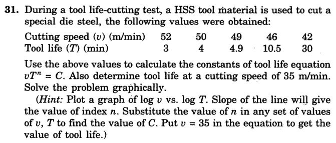
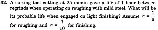
83 Problem 1 While machining cast iron using a high speed steel tool, tool life of 50 minutes was observed when machined with a cutting speed of 100 m/min. determine a) General Taylor s tool life equation, and b) Tool life for a cutting speed of 80 m/min. Assume n=0.09 in Taylor's tool life expression.
84
85 Problem 2 Using Taylor s equation for tool life and taking n=0.5 and c=300, calculate the change in tool life when the cutting speed is reduced by 25%.
86
87 This indicates that the tool life change is T 2 -T 1 /T 1 = T 2 /T 1 1 = = 0.78 i.e., tool life increases by 78% when cutting speed is reduced by 25%
88 Problem 4.3 A carbide- cutting tool when used for machining mild steel work piece material at a cutting speed of 50m/min, lasted for 100 minutes. Determine a) life of the tool when the cutting speed is increased by 25% and b) cutting speed of the tool to get a tool life of 180 minutes. Assume n=0.26 in the Taylor s expression.
89
90 Problem 4.4 In assessing machinability of different work piece materials, the data obtained during machining is given below. Determine the cutting speed for A and B to get a tool life of 50 min. Estimate the relative machinability, considering material A as standard material. Work material Tool life in Min Cutting speed m/min A B
91
92 Problem 27 During the machining of low carbon steel with HSS cutting tool, it was found that for cutting speeds of 40 and 50m/s tool life was 40 and 10 minutes respectively. Derive v-t relationship.
93 Ans: vt 0.16 =72.44
94 Problem 28 The tool life for a high speed steel tool is expressed by the relation vt 1/7 =C 1, and for tungsten carbide is expressed as vt 1/5 =C 2. if at a speed of 24m/min the tool life is 128 minutes, compare the tool life of the two tools at a speed of 30m/min. Ans: T 1 /T 2 =0.64
95
96 Problem 29 A tool life of 80 minutes is obtained at a speed of 30m/min and 8 minutes at 60m/min. Determine the following a) Tool life equation b) Cutting speed for 4 minutes tool life Ans: a)vt 0.3 =C b) m/min
97
98 Problem 30 A carbide tool while machining a mild steel work piece was found to have a life of 1 hour and 40 min when cutting at 50m/min. Find the tool life if the tool is to operate at a speed 30% higher than previous one. Also, calculate the cutting speed if the tool is required to have a life of 2hours and 45 minutes. Assume n=0.28 Ans: T=39 min V=43.4 m/min
99
100
101
102
Metal Cutting (Machining)
") Metal Cutting (Machining) Metal cutting, commonly called machining, is the removal of unwanted portions from a block of material in the form of chips so as to obtain a finished product of desired size,
Metal Cutting (Machining) Metal cutting, commonly called machining, is the removal of unwanted portions from a block of material in the form of chips so as to obtain a finished product of desired size,
Metal Cutting Processes 1 - Turning
 You are here: Home > Handout > Metal Cutting Processes 1 - Turning Metal Cutting Processes 1 - Turning Contents 1. Introduction 2. Center Lathe 3. Cutting Tools 4. Basic Matel Cutting Theory 5. Tool Angles
MANUFACTURING TECHNOLOGY
 MANUFACTURING TECHNOLOGY UNIT III THEORY OF METAL CUTTING Broad classification of Engineering Manufacturing Processes. It is extremely difficult to tell the exact number of various manufacturing processes
AUTOMATED MACHINE TOOLS & CUTTING TOOLS
 CAD/CAM COURSE TOPIC OF DISCUSSION AUTOMATED MACHINE TOOLS & CUTTING TOOLS 1 CNC systems are used in a number of manufacturing processes including machining, forming, and fabrication Forming & fabrication
Materials Removal Processes (Machining)
") Chapter Six Materials Removal Processes (Machining) 6.1 Theory of Material Removal Processes 6.1.1 Machining Definition Machining is a manufacturing process in which a cutting tool is used to remove excess
Chapter Six Materials Removal Processes (Machining) 6.1 Theory of Material Removal Processes 6.1.1 Machining Definition Machining is a manufacturing process in which a cutting tool is used to remove excess
Chapter 24 Machining Processes Used to Produce Various Shapes.
 Chapter 24 Machining Processes Used to Produce Various Shapes. 24.1 Introduction In addition to parts with various external or internal round profiles, machining operations can produce many other parts
Manufacturing Processes(IM 212)
") Arab Academy for Science, Technology, and Maritime Transport Manufacturing Processes(IM 212) Department of Industrial & Management Engineering College of Engineering and Technology Lecture 1 : Introduction
Arab Academy for Science, Technology, and Maritime Transport Manufacturing Processes(IM 212) Department of Industrial & Management Engineering College of Engineering and Technology Lecture 1 : Introduction
THEORY OF METAL CUTTING
 THEORY OF METAL CUTTING INTRODUCTION Overview of Machining Technology Mechanism of chip formation Orthogonal and Oblique cutting Single Point and Multipoint Cutting Tools Machining forces - Merchant s
SAMPLE BOOK TWO AND MACHINING LEARNER RESOURCE MEM05F&MB2/1 FIRST EDITION
 AND MACHINING BOOK TWO LEARNER RESOURCE MEM05 Training Package Units: MEM07005B, MEM07006B, MEM07007B, MEM07008B, MEM07021B, MEM12001B, MEM12006B, MEM12023A MEM05F&MB2/1 FIRST EDITION Publishing details:
 DEPARTMENT OF MECHANICAL ENGINEERING QUESTION BANK ME6402 MANUFACTURING TECHNOLOGY II UNIT I PART A 1. List the various metal removal processes? 2. How chip formation occurs in metal cutting? 3. What is
CHAPTER 23 Machining Processes Used to Produce Various Shapes Kalpakjian Schmid Manufacturing Engineering and Technology 2001 Prentice-Hall Page 23-1
 CHAPTER 23 Machining Processes Used to Produce Various Shapes Manufacturing Engineering and Technology 2001 Prentice-Hall Page 23-1 Examples of Parts Produced Using the Machining Processes in the Chapter
Abrasive Machining Processes. N. Sinha, Mechanical Engineering Department, IIT Kanpur
 Abrasive Machining Processes N. Sinha, Mechanical Engineering Department, IIT Kanpur Introduction Abrasive machining involves material removal by the action of hard, abrasive particles. The use of abrasives
ROOP LAL Unit-6 Lathe (Turning) Mechanical Engineering Department
 Mechanical Engineering Department") Notes: Lathe (Turning) Basic Mechanical Engineering (Part B) 1 Introduction: In previous Lecture 2, we have seen that with the help of forging and casting processes, we can manufacture machine parts of
Notes: Lathe (Turning) Basic Mechanical Engineering (Part B) 1 Introduction: In previous Lecture 2, we have seen that with the help of forging and casting processes, we can manufacture machine parts of
TRAINING MANUAL. Part INTRODUCTION TO TWIST DRILLS
 PRESTO INTERNATIONAL UK LTD TRAINING MANUAL Part 2 INTRODUCTION TO TWIST DRILLS - 1 - DEFINITION:- A rotary end cutting tool having two or more cutting lips, and having two or more spiral (helical) or
TOOL WEAR AND TOOL LIFE
 TOOL WEAR AND TOOL LIFE CONTENTS 4.1 Tool wear During the cutting operation, the cutting edge is stressed mechanically and thermally until it becomes completely blunt and unable to cut, 100 % wear occurs
Hard turning of interrupted surfaces using CBN tools
 journal of materials processing technology 195 (2008) 275 281 journal homepage: www.elsevier.com/locate/jmatprotec Hard turning of interrupted surfaces using CBN tools Anselmo Eduardo Diniz, Adilson José
Chapter 25. Other Machining Processes. Materials Processing. MET Manufacturing Processes. Shaping Planing Broaching Sawing Filing
 MET 33800 Manufacturing Processes Chapter 25 Other Machining Processes Before you begin: Turn on the sound on your computer. There is audio to accompany this presentation. Other Machining Processes Shaping
LANDMARK UNIVERSITY, OMU-ARAN
 LANDMARK UNIVERSITY, OMU-ARAN LECTURE NOTE: DRILLING. COLLEGE: COLLEGE OF SCIENCE AND ENGINEERING DEPARTMENT: MECHANICAL ENGINEERING PROGRAMME: MECHANICAL ENGINEERING ENGR. ALIYU, S.J Course code: MCE
Research on hardened steel turning with superhard tool material
 Research on hardened steel turning with superhard tool material M.Sc. Eng. Jakub Siwiec Supervisor: D.S. Eng. Wojciech Zebala Abstract The paper presents results of research on hardened steel turning with
Design for machining
 Design for machining Machining processes are material removal processes which are a family of shaping operation in which excess or undesired material is removed from the work piece finally remaining with
MANUFACTURING TECHNOLOGY
 MANUFACTURING TECHNOLOGY UNIT IV SURFACE FINISHING PROCESS Grinding Grinding is the most common form of abrasive machining. It is a material cutting process which engages an abrasive tool whose cutting
 VALLIAMMAI ENGINEERING COLLEGE DEPARTMENT OF MECHANICAL ENGINEERING QUESTION BANK ME6402 MANUFACTURING TECHNOLOGY II UNIT-I PART A 1. List the various metal removal processes? (BT1) 2. Explain how chip
Roll No. :.. Invigilator s Signature :.. CS/B.Tech (ME)/SEM-5/ME-504/ TECHNOLOGY OF MACHINING. Time Allotted : 3 Hours Full Marks : 70
/SEM-5/ME-504/ TECHNOLOGY OF MACHINING. Time Allotted : 3 Hours Full Marks : 70") Name : Roll No. :.. Invigilator s Signature :.. CS/B.Tech (ME)/SEM-5/ME-504/2009-10 2009 TECHNOLOGY OF MACHINING Time Allotted : 3 Hours Full Marks : 70 The figures in the margin indicate full marks. Candidates
Name : Roll No. :.. Invigilator s Signature :.. CS/B.Tech (ME)/SEM-5/ME-504/2009-10 2009 TECHNOLOGY OF MACHINING Time Allotted : 3 Hours Full Marks : 70 The figures in the margin indicate full marks. Candidates
Contents 1. Cutting and Cutting Tools 2. Processing by End Mills 3. Cutting Action and Phenomena during Cutting
 Basics of End Mills Contents 1. Cutting and Cutting Tools 2. Processing by End Mills 3. Cutting Action and Phenomena during Cutting Contents 1. Cutting and Cutting Tools 2. Processing by End Mills 3. Cutting
NON-TRADITIONAL MACHINING PROCESSES ULTRASONIC, ELECTRO-DISCHARGE MACHINING (EDM), ELECTRO-CHEMICAL MACHINING (ECM)
, ELECTRO-CHEMICAL MACHINING (ECM)") NON-TRADITIONAL MACHINING PROCESSES ULTRASONIC, ELECTRO-DISCHARGE MACHINING (EDM), ELECTRO-CHEMICAL MACHINING (ECM) A machining process is called non-traditional if its material removal mechanism is basically
NON-TRADITIONAL MACHINING PROCESSES ULTRASONIC, ELECTRO-DISCHARGE MACHINING (EDM), ELECTRO-CHEMICAL MACHINING (ECM) A machining process is called non-traditional if its material removal mechanism is basically
Sharpening Twist Drills. Relief Grinding of the Tool Flanks.
 TOOL WEAR 933 Tool Wear Metal cutting tools wear constantly when they are being used. A normal amount of wear should not be a cause for concern until the size of the worn region has reached the point where
Lecture 15. Chapter 23 Machining Processes Used to Produce Round Shapes. Turning
 Lecture 15 Chapter 23 Machining Processes Used to Produce Round Shapes Turning Turning part is rotating while it is being machined Typically performed on a lathe Turning produces straight, conical, curved,
The role of inclination angle, λ on the direction of chip flow is schematically shown in figure which visualizes that,
 EXPERIMENT NO. 1 Aim: To study of Orthogonal & Oblique Cutting on a Lathe. Experimental set up.: Lathe Machine Theoretical concept: It is appears from the diagram in the following figure that while turning
Grinding. Vipin K Sharma
 Grinding Grinding It is a material cutting process which engages an abrasive tool(in the form of a wheel) whose cutting elements are grains of abrasive material known as grit. These grits are characterized
Think efficiency, Think HSS MILLING
 Think efficiency, Think HSS MILLING SUMMARY MILLING TOOLS 2 Zoom on a milling cutter 3 Which HSS for maximum efficiency? 4 Coatings for the best performance 5 Vocabulary 6 Choose the right design 7 Select
MLR Institute of Technology
 MLR Institute of Technology Dundigal, Quthbullapur (M), Hyderabad 500 043 MECHANICAL ENGINEERING MACHINE TOOLS OBJECTIVE QUESTIONS UNIT - I 1. A built up-edge is formed while machining [ B ] (Sep-2011,
Machining Processes Used to Produce Various Shapes. Dr. Mohammad Abuhaiba
 Machining Processes Used to Produce Various Shapes 1 Homework Assignment Due Wensday 28/4/2010 1. Show that the distance lc in slab milling is approximately equal to for situations where D>>d. (see Figure
Tool and Die Maker Level 2
 Level 2 B2 Read and Interpret Drawings II Duration: 32 hours 32 hours 0 hours This unit of instruction introduces the Tool and Die Maker Apprentice with the knowledge and skills necessary to read and interpret
Review of Various Machining Processes
 Review of Various Machining Processes Digambar O. Jumale 1, Akshay V kharat 2, Akash Tekale 3, Yogesh Sapkal 4,Vinay K. Ghusalkar 5 Department of mechanical engg. 1, 2, 3, 4,5 1, 2, 3, 4,5, PLITMS Buldana
UNIT I THEORY OF METAL CUTTING
 THEORY OF METAL CUTTING & TOOL DESIGN UNIT I THEORY OF METAL CUTTING INTRODUCTION In an industry, metal components are made into different shapes and dimensions by using various metal working processes.
Materials & Processes in Manufacturing
 2003 Bill Young Materials & Processes in Manufacturing ME 151 Chapter 21 Fundamentals of Chip Type Machining Processes 1 Materials Processing 2003 Bill Young 2 Introduction Machining is the process of
INDEXABLE BORING BAR AND INSERTS FLAT TOP, CHIP CONTROL, CBN, AND PCD
 INDEXABLE BORING BAR AND S FLAT TOP, CHIP CONTROL,, AND 80 Diamond.156 IC R.156.040 80 DIAMOND FLAT TOP 80 DIAMOND CHIP CONTROL AT6+ 0.003 ACD5031 ACD5031E AT6+ 0.007 ACD5071 ACD5071E AT6+ 0.015 ACD5151
New. Products2013.
 T u n g a l o y www.tungaloy.com Company Overview Providing Complete Tooling Solutions for the Metal Removal and Industrial Product Sectors TUNGALOY is one of the world s leading manufacturers of carbide
National Conference on Advances in Mechanical Engineering Science (NCAMES-2016)
") Effects of Cutting Fluids and Machining Parameter on Turning of Mild Steel K.G Sathisha 1, V.Lokesh 2, Priyesh 3, 1,2 Assistant professor, Department of Mechanical Engineering, Srinivas Institute of Technology,
Effects of Cutting Fluids and Machining Parameter on Turning of Mild Steel K.G Sathisha 1, V.Lokesh 2, Priyesh 3, 1,2 Assistant professor, Department of Mechanical Engineering, Srinivas Institute of Technology,
FOR IMMEDIATE RELEASE
 FOR IMMEDIATE RELEASE Seco Tools AB Björnbacksvägen 2 73782 Fagersta Sweden Bettina PALMEN Phone: +49 211 2401-313 E-mail: bettina.palmen@secotools.com www.secotools.com Tribological wear analysis Fagersta,
Reamer Basics. Fixed Reamers The reamer size is fixed and any size reduction due to wear or sharpening cannot be reclaimed
 1 Reamer Basics Reamers are available in a variety of types, materials, flute styles and sizes The typical reamer is a rotary cutting tools designed to machine a previously formed hole to an exact diameter
Design for machining
 Multiple choice questions Design for machining 1) Which one of the following process is not a machining process? A) Planing B) Boring C) Turning D) Forging 2) The angle made between the rake face of a
PRODUCT INFORMATION CBN-SXR CBN-LN-SXR CBN-SXB CBN-LN-SXB. CBN End Mill Series
 PRODUCT INFORMATION CBN-LN-SXR CBN-LN-SXB CBN End Mill Series The helical flutes are changing the CBN end mills! Highly Appealing OSG CBN End Mill Series Are you bothered by these issues? The work material
8029 S 200th St. Kent, WA USA Ph: Fax:
 8029 S 200th St. Kent, WA 98032 USA Ph: 253-872-7050 Fax: 253-395-0230 1 GENERAL INFORMATION Rottler CBN and PCD Inserts are laser marked with our part number on one side. On single sided inserts, the
Chapter 23: Machining Processes: Turning and Hole Making
 Manufacturing Engineering Technology in SI Units, 6 th Edition Chapter 23: Machining Processes: Turning and Hole Making Chapter Outline 1. Introduction 2. The Turning Process 3. Lathes and Lathe Operations
Drawing. Fig. 1 Drawing
 Drawing Drawing is a metalworking process which uses tensile forces to stretch metal. It is broken up into two types: sheet metal drawing and wire, bar, and tube drawing. The specific definition for sheet
INTRODUCTION TO GRINDING PROCESS
 GRINDING PART 2 Grinding Grinding is a material removal process accomplished by abrasive particles that are contained in a bonded grinding wheel rotating at very high surface speeds. The rotating grinding
Finishing Process. By Prof.A.Chandrashekhar
 Finishing Process By Prof.A.Chandrashekhar Introduction Finishing process are different from other manufacturing processes. The distinction between the finishing processes and other manufacturing processes
TUBE AND SHEET DRILLS
 TUBE AND SHEET DRILLS 03 Tube and sheet drills The flutes of the RUKO high performance tube and sheet drills are BN ground from the solid hardened form. Because BN (cubical boron nitride) is a much harder
CoroMill. All solutions at a glance
 CoroMill All solutions at a glance CoroMill Product overview Milling grades according to groups Shoulder milling CoroMill 316 CoroMill 490 CoroMill 790 Long edge cutter Insert size Max. cutting depth a
Common Machining Processes
 Common Machining Processes FIGURE 8.1 Some examples of common machining processes. Orthogonal Cutting FIGURE 8.2 Schematic illustration of a two-dimensional cutting process, or orthogonal cutting. (a)
POWER TOOL ACCESSORIES
 POWER TOOL ACCESSORIES SUPER PREMIUM CHALLENGER SEGMENTED SAW 100% hot press Anti clog bond system High premium treated diamonds Effortless fast cutting Segmented 105 1.8 X 8 20 Super Hard Granite and
Lecture 18. Chapter 24 Milling, Sawing, and Filing; Gear Manufacturing (cont.) Planing
 Planing") Lecture 18 Chapter 24 Milling, Sawing, and Filing; Gear Manufacturing (cont.) Planing For production of: Flat surfaces Grooves Notches Performed on long (on average 10 m) workpieces Workpiece moves / Tool
Lecture 18 Chapter 24 Milling, Sawing, and Filing; Gear Manufacturing (cont.) Planing For production of: Flat surfaces Grooves Notches Performed on long (on average 10 m) workpieces Workpiece moves / Tool
Turning Operations. L a t h e
 Turning Operations L a t h e Turning Operations Machine Tool LATHE Job (workpiece) rotary motion Tool linear motions Mother of Machine Tools Cylindrical and flat surfaces Some Typical Lathe Jobs Turning/Drilling/Grooving/
Metal Drilling
 www.irwin.com Metal Drilling Engineered for Controlled Precision and Speed Shank Diameter Shank Point Angle Drill Bit Diameter : The length from the point to the end of the drill bit Point Angle: The angle
Product Information Report Maximizing Drill Bit Performance
 Overview Drills perform three functions when making a hole: Forming the chip The drill point digs into the material and pushes up a piece of it. Cutting the chip The cutting lips take the formed chip away
Catalog 2017/2018. ROENTGEN Over 100 years experience in quality improvement you can t beat it!
 Catalog 2017/2018 ROENTGEN Over 100 years experience in quality improvement you can t beat it! WWW.ROENTGEN-USA.COM CONTENTS THE COMPANY OVER 100 YEARS EXPERIENCE 04 TECHNIQUE TOOTH PITCHES 06 SET PATTERNS
CHAPTER-1 INTRODUCTION. S.No. Name of the Sub-Title Page No. 1.1 Introduction Manufacturing System Metal Cutting 4
 1 CHAPTER-1 INTRODUCTION S.No. Name of the Sub-Title Page No. 1.1 Introduction 2 1.2 Manufacturing System 3 1.3 Metal Cutting 4 1.3.1 Independent Input Variables 4 1.3.2 Dependent Variables 6 1.3.3 Relations
1
 www.icwahelpn.co.in 1 Operation Management Objective Type Question s and Answer s 1. Fill up the blanks: 1. Intension of modern industries is to create appropriate number of useful at reasonable price.
Roughing vs. finishing
 Finishing methods Roughing vs. finishing Roughing removing material as fast as possible, without special demands on surface and low demand on precision high Q, high IT, high Ra Finishing making final surface
SHAPING AND PLANING Shaping and planing
 SHAPING AND PLANING Shaping and planing the simplest of all machine operations Straight line cutting motion with single-point cutting tool creates smooth flat surfaces. Mainly plain surfaces are machined
Severance Offers Four Types of Hand Files To Solve Virtually Every Application
 are Great for Many Application Filing Deburring Shaping Forming Chamfering Sharpening Smoothing Beveling De-Flashing Trimming and De-Scaling Severance Offers Four Types of To Solve Virtually Every Application
EXPERIMENTAL STUDY ON TURNING WITH SELF-PROPELLED ROTARY CUTTING TOOL
 Journal of Thermal Engineering, Vol. 3, No. 6, Special Issue 6, pp. 1553-156, Yildiz Technical University Press, Istanbul, Turkey EXPERIMENTAL STUDY ON TURNING WITH SELF-PROPELLED ROTARY CUTTING TOOL U.
ROENTGEN Over 100 years experience in quality improvement you can t beat it!
 Catalog 2015/2016 ROENTGEN Over 100 years experience in quality improvement you can t beat it! WWW.ROENTGEN-SAW.COM CONTENTS THE COMPANY OVER 100 YEARS EXPERIENCE 04 TECHNIQUE TOOTH PITCHES 06 SET PATTERNS
Tool Wear Performance of CVD-Insert during Machining of Ti-6%Al-4%V ELI at High Cutting Speed
 Key Engineering Materials Vol. 443 (2010) pp 371-375 (2010) Trans Tech Publications, Switzerland doi:10.4028/www.scientific.net/kem.443.371 Tool Wear Performance of CVD-Insert during Machining of Ti-6%Al-4%V
Grade/Chip breaker. Contents. Grades. Chip breakers A02 A03 A04. Korloy grades system Grade selection system The feature of korloy grades A06 A08 A09
 Grade/Chip breaker Contents Korloy grades system Grade selection system The feature of korloy grades A02 A03 A04 For For For A06 A08 A09 >>> /Chipbreakers Korloy grades system Uncoated P For steel ST05
CHAPTER 1- INTRODUCTION TO MACHINING
 CHAPTER 1- INTRODUCTION TO MACHINING LEARNING OBJECTIVES Introduction to Manufacturing, Manufacturing processes Broad classification of Manufacturing processes Kinematics elements involved in metal cutting
Investigation And Optimization Of Various Machining Parameters Affecting The Effectiveness Of Turning: A Review
 Investigation And Optimization Of Various Machining Parameters Affecting The Effectiveness Of Turning: A Review 1 S B Chikalthankar Assistant Professor Department of Mechanical Engineering, Government
Trade of Toolmaking. Module 3: Milling Unit 9: Precision Vee Block Assembly Phase 2. Published by. Trade of Toolmaking Phase 2 Module 3 Unit 9
 Trade of Toolmaking Module 3: Milling Unit 9: Precision Vee Block Assembly Phase 2 Published by SOLAS 2014 Unit 9 1 Table of Contents Document Release History... 3 Unit Objective... 4 Introduction... 4
Various other types of drilling machines are available for specialized jobs. These may be portable, bench type, multiple spindle, gang, multiple
 Drilling The process of making holes is known as drilling and generally drilling machines are used to produce the holes. Drilling is an extensively used process by which blind or though holes are originated
MILLING and GRINDING MACHINES Machine Tools
 ELEMENTS OF MECHANICAL ENGINEERING PART B UNIT VI MILLING and GRINDING MACHINES Machine Tools 1 Objectives: 1.1 To understand the Principle of working of Milling, Horizontal & Vertical Milling. 1.2 Classification/Types
Machining vs. Grinding
 University of Connecticut Machining vs. Grinding -- Towards High Efficiency Machining Bi Zhang Mechanical Engineering zhang@engr.uconn.edu Presentation Sequence Introduction High Speed Machining High Speed
Twist Drills for Woodworkers. Standard twist drills and two methods of sharpening 10 January 2015 Marc Pohm
 Twist Drills for Woodworkers Standard twist drills and two methods of sharpening 10 January 2015 Marc Pohm Twist Drills for Woodworking Topics that will be covered: Coatings Steel Types Drill Points Drill
Copyright 2008 Society of Manufacturing Engineers. FUNDAMENTALS OF TOOL DESIGN Cutting Tool Design
 FUNDAMENTALS OF TOOL DESIGN Cutting Tool Design SCENE 1. CT25A, CGS: Single-Point Cutting Tool Design white text, centered on background FTD01B, motion background SCENE 2. CT26A, tape FTD21, 01:03:22:00-01:03:33:00
Study on Tool Life and its Failure Mechanisms
 IJIRST International Journal for Innovative Research in Science & Technology Volume 2 Issue 04 September 2015 ISSN (online): 2349-6010 Study on Tool Life and its Failure Mechanisms M. Pradeep Kumar N.
EFFECT OF CUTTING PARAMETERS ON THE TOOL WEAR AND TOOL LIFE IN DRY ENVIRONMENT A REVIEW
 EFFECT OF CUTTING PARAMETERS ON THE TOOL WEAR AND TOOL LIFE IN DRY ENVIRONMENT A REVIEW NILESH D. JALAN [1], V.N. KSHIRSAGAR [2] [1] B.E. (pursuing), Department of Mechanical Engineering, G.H. Raisoni
BASIC TECHNICAL INFORMATION FOR REAMERS FLUTE STYLES
 BASIC TECHNICAL INFORMATION FOR HANNIBAL CARBIDE would like to inform you of some basic technical knowledge regarding reamers. Following these guidelines will reduce overall set-up time, while increasing
A Pictorial Odyssey. Grinding: An examination of the grinding process through the lens of an electron microscope. By Dr.
 Grinding: A Pictorial Odyssey A FEBRUARY 2009 / VOLUME 61 / ISSUE 2 By Dr. Jeffrey Badger An examination of the grinding process through the lens of an electron microscope. picture is worth a thousand
Understanding the basics of Spiral Pointed Taps. July 2017
 Understanding the basics the of Spiral Basics Pointed Taps of Spiral Pointed Taps July 2017 Understanding the Basics of Spiral Pointed Taps What is a spiral pointed taps? Cutting torque of spiral pointed
High-Efficiency Cutting of Super-Heat-Resistant Alloy
 12 High-Efficiency Cutting of Super-Heat-Resistant Alloy Keiichi Yamamoto *1 Motofumi Kuroda *1 Hidefumi Omokawa *1 Katsutoshi Itakura *2 Inconel 718, a super-heat-resisting alloy, is difficult to cut,
Band Machining. Chapter 20
 Chapter 20 Band Machining LEARNING OBJECTIVES After studying this chapter, students will be able to: Describe how a band machine operates. Explain the advantages of band machining. Select the proper blade
Elimination of Honing Stick Mark in Rack Tube B.Parthiban1 1, N.Arul Kumar 2, K.Gowtham Kumar 3, P.Karthic 4, R.Logesh Kumar 5
 Elimination of Honing Stick Mark in Rack Tube B.Parthiban1 1, N.Arul Kumar 2, K.Gowtham Kumar 3, P.Karthic 4, R.Logesh Kumar 5 Assistant Professor, Dept. of Mechanical Engineering, Jay Shriram Group of
FUNDAMENTAL MANUFACTURING PROCESSES Plastics Machining & Assembly NARRATION (VO): NARRATION (VO): NARRATION (VO): INCLUDING: METALS,
: NARRATION (VO): NARRATION (VO): INCLUDING: METALS,") Copyright 2002 Society of Manufacturing Engineers --- 1 --- FUNDAMENTAL MANUFACTURING PROCESSES Plastics Machining & Assembly SCENE 1. CG: Plastics Machining white text centered on black SCENE 2. tape
Copyright 2002 Society of Manufacturing Engineers --- 1 --- FUNDAMENTAL MANUFACTURING PROCESSES Plastics Machining & Assembly SCENE 1. CG: Plastics Machining white text centered on black SCENE 2. tape
ROOP LAL Unit-6 (Milling) Mechanical Engineering Department
 Mechanical Engineering Department") Notes: Milling Basic Mechanical Engineering (Part B, Unit - I) 1 Introduction: Milling is a machining process which is performed with a rotary cutter with several cutting edges arranged on the periphery
Notes: Milling Basic Mechanical Engineering (Part B, Unit - I) 1 Introduction: Milling is a machining process which is performed with a rotary cutter with several cutting edges arranged on the periphery
SEMI MAGNETIC ABRASIVE MACHINING
 4 th International Conference on Mechanical Engineering, December 26-28, 21, Dhaka, Bangladesh/pp. V 81-85 SEMI MAGNETIC ABRASIVE MACHINING P. Jayakumar Priyadarshini Engineering College, Vaniyambadi 635751.
TURNING BORING TURNING:
 TURNING BORING TURNING: FACING: Machining external cylindrical and conical surfaces. Work spins and the single cutting tool does the cutting. Done in Lathe. Single point tool, longitudinal feed. Single
MACHINING PROCESSES: TURNING AND HOLE MAKING. Dr. Mohammad Abuhaiba 1
 MACHINING PROCESSES: TURNING AND HOLE MAKING Dr. Mohammad Abuhaiba 1 HoweWork Assignment Due Wensday 7/7/2010 1. Estimate the machining time required to rough cut a 0.5 m long annealed copper alloy round
11/15/2009. There are three factors that make up the cutting conditions: cutting speed depth of cut feed rate
 s Geometry & Milling Processes There are three factors that make up the cutting conditions: cutting speed depth of cut feed rate All three of these will be discussed in later lessons What is a cutting
EXPERIMENTAL INVESTIGATION OF EFFECT OF CUTTING PARAMETERS ON HSS TOOL LIFE IN TURNING OPERATION
 EXPERIMENTAL INVESTIGATION OF EFFECT OF CUTTING PARAMETERS ON HSS TOOL LIFE IN TURNING OPERATION Nitin Jain 1, Prof. Swati D. Chaugaonkar 2 1 Nitin Jain Student, M.E. (Tribology and maintenance), 2 Assistant
Router Section 2018 Master Catalog
 Router Section 2018 Master Catalog For more than 95 years, M.A. Ford has been at the cutting edge of tooling design and manufacturing and has developed an enviable global reputation for performance and
TAW Drill. Indexable insert drill, yet always stable drilling. Stable drilling with indexable drill B060A. MIRACLE Coated VP15TF
 B060A Stable drilling with indexable drill Indexable insert drill, yet always stable drilling Grade for high rigidity and longer tool life MIRACLE Coated MIRACLE coating displays high welding resistance
ANALYSIS OF SURFACE ROUGHNESS WITH VARIATION IN SHEAR AND RAKE ANGLE
 ANALYSIS OF SURFACE ROUGHNESS WITH VARIATION IN SHEAR AND RAKE ANGLE Sirajuddin Elyas Khany 1, Mohammed Hissam Uddin 2, Shoaib Ahmed 3, Mohammed Wahee uddin 4 Mohammed Ibrahim 5 1 Associate Professor,
Lathe is a machine, which removes the metal from a piece of work to the required shape & size HENRY MAUDSLAY
 TURNING MACHINES LATHE Introduction Lathe is a machine, which removes the metal from a piece of work to the required shape & size HENRY MAUDSLAY - 1797 Types of Lathe Engine Lathe The most common form
Metal Drilling.
 101 ENGINEERED FOR CONTROLLED PRECISION AND SPEED The IRWIN line of metal drill bits offers of solution for every professional application. Each metal drill bit is made of high speed steel with high precision-cut
INDEX. S.No. Name of the Experiment Page No.
 MACHINE TOOLS LAB INDEX S.No. Name of the Experiment Page No. 1 Step Turning and Taper Turning on Lathe 2 Thread Cutting and Knurling on Lathe 3 Machining Flat Surface using Shaper Machine 4 Manufacturing
External Turning. Outline Review of Turning. Cutters for Turning Centers
 Outline Review of Turning External Turning 3 External Turning Parameters Cutting Tools Inserts Toolholders Machining Operations Roughing Finishing General Recommendations Turning Calculations Machining
Features. Special forms are possible
 Center Drill >> The is a trademark of Nine9, the developer of the first indexable center drill in the world.(patented) Offering an indexable insert system for the 1st time, Nine9 s design improves your
Table of Contents. Production Options 3. Suggested Tooling 4. Special Considerations 4. Sawing 4. Holding 5. Turning 5. Milling 6.
 Table of Contents Production Options 3 Suggested Tooling 4 Special Considerations 4 Sawing 4 Holding 5 Turning 5 Milling 6 Drilling 6 Threading 7 Grinding 7 Buffing and Polishing 8 Deburring 8 Lapping
Drona Gyaan MACHINING-INTRODUCTION
 Drona Gyaan MACHINING-INTRODUCTION Manufacturing is a VALUE ADDITION process by which raw materials or objects of low value due to inadequate material properties, poor or irregular size, shape and finish
Your Specials Are Our Standards TM
 09/2010 TM Your Specials Are Our Standards TM 400 New Tools Inside! See Inside Cover For Details ALL TOOLS IN STOCK! SAME DAY SHIPPING! Harvey Tool Company, LLC 319 Newburyport Turnpike Rowley, MA 01969