Chapter 25. Other Machining Processes. Materials Processing. MET Manufacturing Processes. Shaping Planing Broaching Sawing Filing
|
|
|
- Imogen Potter
- 5 years ago
- Views:
Transcription

1 MET Manufacturing Processes Chapter 25 Other Machining Processes Before you begin: Turn on the sound on your computer. There is audio to accompany this presentation. Other Machining Processes Shaping Planing Broaching Sawing Filing Chapter 25-2 Materials Processing Chapters Chapters Chapters Chapters Chapter


2 Shaping and Planing Among oldest single-point machining methods. Largely replaced by milling and broaching for production operations. Chapter 25-4 Shaping and Planing Types of geometry commonly machined using shaping or planing methods. Chapter 25-5 Shaping and Planing Chapter


3 Shaping Workpiece feed at right angle to cutting motion. Single point cutting tool held in ram and reciprocates across workpiece. Cutting occurs on forward stroke only (clapper box prevents tool drag). Chapter 25-7 Shaping Chapter 25-8 Shaping Machines Machine types: Horizontal: push-cut or pull (draw)-cut Vertical: regular (slotter) or keysetter Special Chapter
 N S = #strokes/min (rpm) R S = stroke ratio (no units) L = length being cut W =")


4 Shaping Machines Chapter Shaping Cutting Parameters Cutting parameters: V = cutting speed L S = length of stroke (in) N S = #strokes/min (rpm) R S = stroke ratio (no units) L = length being cut W = width being cut t = depth of cut f c = feed in/stroke 2 L N S S V = 12 R S cutting stroke angle R = S o 360 L W t MRR = CT W T = m N f S c o Chapter Planing Workpiece feed at right angle to cutting motion. Workpiece is moved past multiple single point cutting tools that are held stationary. Tool heads can be arranged for cutting in both directions. Very slow process applicable to only very large workpieces. Chapter

.")

5 Planing Machines Chapter Broaching Entire surface generated in single pass of broach. Broach composed of series of teeth, each tooth slightly higher. Feed per tooth is change in height of successive teeth. Feed per tooth is built into cutting tool (unique to process). Chapter Broaching Broach may be stationary or move past work. Internal & external broaching possible. Used for mass production due to cost of broach ($15-30K). Better accuracy and finish than drilling, boring or reaming. Speed relatively low sfpm. Chapter


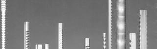
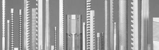
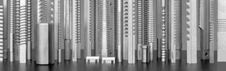
6 Broaching Chapter Broaching Chapter Broach Design Chapter

 or step - determines amount")
7 Broach Design Chapter Broach Design 1. Each tooth is single-edge cutting tool. Chapter Broach Design 2. Rise per tooth (RPT) or step - determines amount of material removed. Chapter
 0.003 RPT Finishing (depth of cut t f ) 0.001 RPT Burnishing rounded disks with no cutting edge. 0.001-0.003 RPT. Chapter 25-23 Broach Design 4.")
8 Broach Design 3. Pitch (P) distance between teeth. Minimum of two teeth engaged in work. L W = length of cut P 0.35 LW Chapter Broach Design 4. Tooth style: Roughing (depth of cut t r ) RPT Semi-finishing (depth of cut t s ) RPT Finishing (depth of cut t f ) RPT Burnishing rounded disks with no cutting edge RPT. Chapter Broach Design 4. Tooth style (continued): DOC = depth of cut n = number of teeth t = rise per tooth n = r DOC - n t - n t t r f f s s Chapter
 Rotor-cut (Jump-cut): Two or three teeth have same height with cut-away so each tooth")
: b) Double-cut: Four teeth have same height and progressively get")
 Progressive: First few teeth machine to center, remaining teeth offset and finish remaining surface area.")
9 Broach Design 5. Broach design: a) Rotor-cut (Jump-cut): Two or three teeth have same height with cut-away so each tooth machines only a portion of the surface. Allows deeper and narrower cuts. Reduces force and power requirements. Chapter Broach Design 5. Broach design (continued): b) Double-cut: Four teeth have same height and progressively get wider. c) Progressive: First few teeth machine to center, remaining teeth offset and finish remaining surface area. Chapter Broach Design 5. Broach design (continued): d) Chip-Breakers: Same function as other chipbreakers on other cutting tools. Break long continuous chips in ductile materials. Chapter
. 7.")

10 Broach Design 6. Tooth angle: Normal to direction of cut to 5-20º angle (shear-cut broach). 7. Hook: Primary rake angle. 8. Back-off: End clearance to prevent rubbing. 9. Front pilot: Aligns broach in hole before cut begins. 10. Rear pilot: Keeps broach square as tool leaves workpiece. Chapter Broach Design Chapter Broach Design Chapter


11 Broach Design Chapter Broach Design Chapter Machining Parameters MRR = 12 t r W V n r W = width (circumference) of tooth t r = roughing teeth RPT n r = # roughing teeth T m = L / 12V L = length of stroke Chapter
12 Broach Design Parameters Allowable Pull (AP) area of min section Y.S. AP = S Y.S. = yield strength of broach S = safety factor Chapter Broach Design Parameters Allowable Load (AL) 13.5 x 10 D AL = S L 6 4 r 2 D r = root diameter S = safety factor L = length from push end to first tooth Chapter Machining Parameters Pull Force F CB 5 S nt r W S = shear stress of material W = width (circumference) of tooth t r = roughing teeth RPT n = #total teeth Chapter

13 Broach Design and Machining Parameters Example Process: Pull Broaching Part Configuration: 1.0 diameter ID shape x 3.0 long depth of cut Part Material: 1018 Annealed Carbon Steel V = 20 fpm S = psi Broach Y.S. = 260,000 psi Chapter Broach Design and Machining Parameters Example Chapter Broach Design and Machining Parameters Example Chapter
14 Broach Design and Machining Parameters Example Chapter Broach Design and Machining Parameters Example Chapter Broach Design and Machining Parameters Example Chapter
 Pull down (internal) - broach elevator above and pulling mechanism below table. c) Pull up (internal) - pulling mechanism above and handling mechanism below table.")
15 Machining Parameters Example Chapter Broaching Machines 1. Vertical a) Broaching press - arbor press with guided ram. b) Pull down (internal) - broach elevator above and pulling mechanism below table. c) Pull up (internal) - pulling mechanism above and handling mechanism below table. d) Surface - broach mounted in guide slides. Chapter Broaching Machines Chapter


 Continuous - broach stationary and work pulled past on")
16 Broaching Machines Chapter Broaching Machines Chapter Broaching Machines 2. Horizontal - longer lengths. a) Internal typically push / not used for small holes since broach must be self-supporting. b) Surface - broach supported in guides. c) Continuous - broach stationary and work pulled past on conveyor. 3. Rotary - broach stationary and work rotated past on table. Chapter


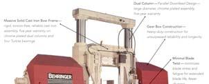
17 Broaching Machines Horizontal Surface Broaching Machine Turbine Wheel Blade Roots Rotary Broaching Machine Chapter Broaching Machines Horizontal Internal Broaching Machine Gun Barrel Bore Chapter Broaching Machines Chapter


18 Broaching Machines Chapter Sawing Chips generated by teeth located on periphery of blade. Chapter Sawing Chapter


 saw blades: a.")
19 Sawing Chapter Blade Types 1. Hacksaw blades: a. Hand: thick (gage) 10 or 12 inch length ½ wide b. Power: thick 12 to 24 inch length 1 2 wide Chapter Blade Types 2. Bandsaw blades: a. 1/16 and greater width 3. Circular (cold) saw blades: a. Teeth cut into disk up to 18 dia. b. Segmented or inserted teeth used for larger diameter blades. Chapter


20 Blade Types Circular (cold) saw blades: segmented or inserted teeth larger diameters. Chapter Blade Types Cold saw blade with carbide teeth Chapter Blade Types Cold saw blade: segmented teeth Chapter


21 Blade Nomenclature Chapter Blade Design 1. Blade Material: a. Hacksaw: Tungsten or molybdenum HSS. b. Bandsaw: HSS, Brazed Carbide, TiN Coated. c. Cold Saw: HSS, Brazed Carbide, TiN Coated. d. Friction Saw: Abrasive. Chapter Blade Design 2. Tooth forms: a. Regular tooth: general purpose, ferrous materials. b. Skip tooth: softer, non-ferrous materials. c. Hook tooth: harder, non-ferrous materials. d. Variable pitch: wider range of applications including tubing. Reduced vibration. Chapter


22 Blade Design 3. Tooth spacing: a. Determines how many teeth engage work (minimum two required). b. Controls size of teeth. c. Determines gullet. Chapter Blade Design 4. Tooth set - how teeth are offset from centerline controls size of teeth. a. Raker-set: General purpose, uniform thickness, steel and iron. b. Straight-set: Brass, copper, plastic. c. Wave-set: Thin sheet or wall tubing, non-uniform thickness. d. Cluster-set: Thin sheet or wall tubing, non-uniform thickness. Chapter Blade Design 5. Gage: measure of blade thickness. 6. Width: controls the minimum radius bandsaw blade is capable of cutting. Chapter


23 Sawing Machines 1. Reciprocating saw - hand or power with optional automatic power bar feed mechanisms. 2. Bandsaw: a. Vertical cutoff - single stationary workpiece on table. b. Horizontal cutoff - can incorporate optional automatic power bar feed mechanisms. c. Combination cutoff and contour - like DoAll in lab. d. Friction - blade brings metal to melting point and pulls material from kerf. Chapter Sawing Machines Chapter Sawing Machines Chapter


24 Sawing Machines Chapter Sawing Machines Chapter Sawing Machines Chapter


25 Sawing Machines Chapter Sawing Machines Friction Bandsaw Chapter Sawing Machines 3. Circular saw : a. Cold saw - cutoff work exclusively. b. Steel friction disk - similar to bandsaw. c. Abrasive disk - technically not sawing but machine function is the same. Chapter


26 Filing Metal removal action same as sawing except chips are very small and cutting teeth are wider. Cutting action is very slow and easily controlled with high accuracy. Includes manual and machine-based operation. Chapter File Characteristics 1. Type or cut of teeth: a. Single-cut - rows of parallel teeth at angle. b. Double-cut - two series of parallel teeth. c. Vixen-cut - parallel curved teeth. d. Rasp-cut - teeth short and raised out of file. Chapter File Characteristics 2. Degree of coarseness: a. Swiss - #00 to #8 roughness increasing b. Dead Smooth c. Smooth d. Second Cut e. Bastard f. Coarse g. Rough Chapter


27 File Characteristics 3. Construction a. Tang for file handle. b. Cross-section: a. Flat b. Round c. Square d. Triangle e. Half-round Chapter Filing Machines Die filing - reciprocate file. Band filing - bandsaws with special blades. Lower accuracy. Disk-filing machines - files in form of disk. Low accuracy. Chapter Filing Machines Chapter

28 The End See Oncourse for Videos Chapter
Other Machining Operations
 Other Machining Operations Chapter 25 25.1 Introduction This chapter covers: Shaping Planing Broaching Sawing Filing 25.2 Introduction to Shaping and Planing Shaping and Planing among the oldest techniques
Lecture 18. Chapter 24 Milling, Sawing, and Filing; Gear Manufacturing (cont.) Planing
 Planing") Lecture 18 Chapter 24 Milling, Sawing, and Filing; Gear Manufacturing (cont.) Planing For production of: Flat surfaces Grooves Notches Performed on long (on average 10 m) workpieces Workpiece moves / Tool
Lecture 18 Chapter 24 Milling, Sawing, and Filing; Gear Manufacturing (cont.) Planing For production of: Flat surfaces Grooves Notches Performed on long (on average 10 m) workpieces Workpiece moves / Tool
Chapter 24 Machining Processes Used to Produce Various Shapes.
 Chapter 24 Machining Processes Used to Produce Various Shapes. 24.1 Introduction In addition to parts with various external or internal round profiles, machining operations can produce many other parts
Chapter 23 Drilling and Hole Making Processes. Materials Processing. Hole Making Processes. MET Manufacturing Processes
 MET 33800 Manufacturing Processes Chapter 23 Drilling and Hole Making Processes Before you begin: Turn on the sound on your computer. There is audio to accompany this presentation. Materials Processing
Machining Processes Used to Produce Various Shapes. Dr. Mohammad Abuhaiba
 Machining Processes Used to Produce Various Shapes 1 Homework Assignment Due Wensday 28/4/2010 1. Show that the distance lc in slab milling is approximately equal to for situations where D>>d. (see Figure
Bandsaw Blade Selection Guide
 Bandsaw Blade Selection Guide 1. Determine Blade Length Refer to your manual for a specified length. or Stretch out an existing blade and measure it. or Set the wheels to the centre of the adjusting bolt
Materials & Processes in Manufacturing
 2003 Bill Young Materials & Processes in Manufacturing ME 151 Chapter 21 Fundamentals of Chip Type Machining Processes 1 Materials Processing 2003 Bill Young 2 Introduction Machining is the process of
 DEPARTMENT OF MECHANICAL ENGINEERING QUESTION BANK ME6402 MANUFACTURING TECHNOLOGY II UNIT I PART A 1. List the various metal removal processes? 2. How chip formation occurs in metal cutting? 3. What is
CHAPTER 23 Machining Processes Used to Produce Various Shapes Kalpakjian Schmid Manufacturing Engineering and Technology 2001 Prentice-Hall Page 23-1
 CHAPTER 23 Machining Processes Used to Produce Various Shapes Manufacturing Engineering and Technology 2001 Prentice-Hall Page 23-1 Examples of Parts Produced Using the Machining Processes in the Chapter
ROOP LAL Unit-6 (Milling) Mechanical Engineering Department
 Mechanical Engineering Department") Notes: Milling Basic Mechanical Engineering (Part B, Unit - I) 1 Introduction: Milling is a machining process which is performed with a rotary cutter with several cutting edges arranged on the periphery
Notes: Milling Basic Mechanical Engineering (Part B, Unit - I) 1 Introduction: Milling is a machining process which is performed with a rotary cutter with several cutting edges arranged on the periphery
ROOP LAL Unit-6 Lathe (Turning) Mechanical Engineering Department
 Mechanical Engineering Department") Notes: Lathe (Turning) Basic Mechanical Engineering (Part B) 1 Introduction: In previous Lecture 2, we have seen that with the help of forging and casting processes, we can manufacture machine parts of
Notes: Lathe (Turning) Basic Mechanical Engineering (Part B) 1 Introduction: In previous Lecture 2, we have seen that with the help of forging and casting processes, we can manufacture machine parts of
A H M 531 The Civil Engineering Center
 Title Page Introduction 2 Objectives 2 Theory 2 Fitting 3 Turning 5 Shaping and Grinding 7 Milling 8 Conclusion 11 Reference 11 1 Introduction Machining Machining is a manufacturing process in which a
 VALLIAMMAI ENGINEERING COLLEGE DEPARTMENT OF MECHANICAL ENGINEERING QUESTION BANK ME6402 MANUFACTURING TECHNOLOGY II UNIT-I PART A 1. List the various metal removal processes? (BT1) 2. Explain how chip
AUTOMATED MACHINE TOOLS & CUTTING TOOLS
 CAD/CAM COURSE TOPIC OF DISCUSSION AUTOMATED MACHINE TOOLS & CUTTING TOOLS 1 CNC systems are used in a number of manufacturing processes including machining, forming, and fabrication Forming & fabrication
Review of Various Machining Processes
 Review of Various Machining Processes Digambar O. Jumale 1, Akshay V kharat 2, Akash Tekale 3, Yogesh Sapkal 4,Vinay K. Ghusalkar 5 Department of mechanical engg. 1, 2, 3, 4,5 1, 2, 3, 4,5, PLITMS Buldana
Design for machining
 Multiple choice questions Design for machining 1) Which one of the following process is not a machining process? A) Planing B) Boring C) Turning D) Forging 2) The angle made between the rake face of a
Materials Removal Processes (Machining)
") Chapter Six Materials Removal Processes (Machining) 6.1 Theory of Material Removal Processes 6.1.1 Machining Definition Machining is a manufacturing process in which a cutting tool is used to remove excess
Chapter Six Materials Removal Processes (Machining) 6.1 Theory of Material Removal Processes 6.1.1 Machining Definition Machining is a manufacturing process in which a cutting tool is used to remove excess
Chapter 22 MACHINING OPERATIONS AND MACHINE TOOLS
 Chapter 22 MACHINING OPERATIONS AND MACHINE TOOLS Turning and Related Operations Drilling and Related Operations Milling Machining Centers and Turning Centers Other Machining Operations High Speed Machining
Lecture 15. Chapter 23 Machining Processes Used to Produce Round Shapes. Turning
 Lecture 15 Chapter 23 Machining Processes Used to Produce Round Shapes Turning Turning part is rotating while it is being machined Typically performed on a lathe Turning produces straight, conical, curved,
Band Machining. Chapter 20
 Chapter 20 Band Machining LEARNING OBJECTIVES After studying this chapter, students will be able to: Describe how a band machine operates. Explain the advantages of band machining. Select the proper blade
MANUFACTURING TECHNOLOGY
 MANUFACTURING TECHNOLOGY UNIT V Machine Tools Milling cutters Classification of milling cutters according to their design HSS cutters: Many cutters like end mills, slitting cutters, slab cutters, angular
SHAPING AND PLANING Shaping and planing
 SHAPING AND PLANING Shaping and planing the simplest of all machine operations Straight line cutting motion with single-point cutting tool creates smooth flat surfaces. Mainly plain surfaces are machined
SHAPER, MILLING AND GEAR CUTTING MACHINES
 UNIT 3 SHAPER, MILLING AND GEAR CUTTING MACHINES 1. Compare hydraulic shaper with mechanical shaper? SL.NO Hydrulic shaper Mechanical shaper 1. smooth cutting operation Rough and noisy cutting operation
Chapter 24. Machining Processes Used to Produce Various Shapes: Milling, Broaching, Sawing, and Filing; Gear Manufacturing
 Chapter 24 Machining Processes Used to Produce Various Shapes: Milling, Broaching, Sawing, and Filing; Gear Manufacturing Parts Made with Machining Processes of Chapter 24 Figure 24.1 Typical parts and
TURNING BORING TURNING:
 TURNING BORING TURNING: FACING: Machining external cylindrical and conical surfaces. Work spins and the single cutting tool does the cutting. Done in Lathe. Single point tool, longitudinal feed. Single
Trade of Toolmaking. Module 3: Milling Unit 9: Precision Vee Block Assembly Phase 2. Published by. Trade of Toolmaking Phase 2 Module 3 Unit 9
 Trade of Toolmaking Module 3: Milling Unit 9: Precision Vee Block Assembly Phase 2 Published by SOLAS 2014 Unit 9 1 Table of Contents Document Release History... 3 Unit Objective... 4 Introduction... 4
Workshop Practice TA 102 Lec 6 & 7 :Theory of Metal Cutting. By Prof.A.Chandrashekhar
 Workshop Practice TA 102 Lec 6 & 7 :Theory of Metal Cutting By Prof.A.Chandrashekhar Theory of Metal cutting INTRODUCTION: The process of manufacturing a component by removing the unwanted material using
Catalog 2017/2018. ROENTGEN Over 100 years experience in quality improvement you can t beat it!
 Catalog 2017/2018 ROENTGEN Over 100 years experience in quality improvement you can t beat it! WWW.ROENTGEN-USA.COM CONTENTS THE COMPANY OVER 100 YEARS EXPERIENCE 04 TECHNIQUE TOOTH PITCHES 06 SET PATTERNS
Product Information Report Hardflex Band Saw Blades
 Overview Hardflex Bandsaw Blades are great all-purpose blades for cutting almost any metal. Cuts tough material like stainless steel. Works equally well on solids, tubing and structural shapes. Features/Benefits
Metal Cutting (Machining)
") Metal Cutting (Machining) Metal cutting, commonly called machining, is the removal of unwanted portions from a block of material in the form of chips so as to obtain a finished product of desired size,
Metal Cutting (Machining) Metal cutting, commonly called machining, is the removal of unwanted portions from a block of material in the form of chips so as to obtain a finished product of desired size,
TRAINING MANUAL. Part INTRODUCTION TO TWIST DRILLS
 PRESTO INTERNATIONAL UK LTD TRAINING MANUAL Part 2 INTRODUCTION TO TWIST DRILLS - 1 - DEFINITION:- A rotary end cutting tool having two or more cutting lips, and having two or more spiral (helical) or
Manufacturing Processes(IM 212)
") Arab Academy for Science, Technology, and Maritime Transport Manufacturing Processes(IM 212) Department of Industrial & Management Engineering College of Engineering and Technology Lecture 1 : Introduction
Arab Academy for Science, Technology, and Maritime Transport Manufacturing Processes(IM 212) Department of Industrial & Management Engineering College of Engineering and Technology Lecture 1 : Introduction
THEORY OF METAL CUTTING
 THEORY OF METAL CUTTING INTRODUCTION Overview of Machining Technology Mechanism of chip formation Orthogonal and Oblique cutting Single Point and Multipoint Cutting Tools Machining forces - Merchant s
Broaches The basic characteristic
 Broaches The basic characteristic Broaches handle mass production with high accuracy and high efficiency. It is very important to point out that complex shapes can be steadily produced without requiring
Roll No. :.. Invigilator s Signature :.. CS/B.Tech (ME)/SEM-5/ME-504/ TECHNOLOGY OF MACHINING. Time Allotted : 3 Hours Full Marks : 70
/SEM-5/ME-504/ TECHNOLOGY OF MACHINING. Time Allotted : 3 Hours Full Marks : 70") Name : Roll No. :.. Invigilator s Signature :.. CS/B.Tech (ME)/SEM-5/ME-504/2009-10 2009 TECHNOLOGY OF MACHINING Time Allotted : 3 Hours Full Marks : 70 The figures in the margin indicate full marks. Candidates
Name : Roll No. :.. Invigilator s Signature :.. CS/B.Tech (ME)/SEM-5/ME-504/2009-10 2009 TECHNOLOGY OF MACHINING Time Allotted : 3 Hours Full Marks : 70 The figures in the margin indicate full marks. Candidates
PQ G-P01[ ].qxd 1/24/04 9:10 AM Page 1 Quark03 Quark03:Desktop Folder:REPRO-miller. Power Hacksaws, Power Band Saws, and Circular Saws
![PQ G-P01[ ].qxd 1/24/04 9:10 AM Page 1 Quark03 Quark03:Desktop Folder:REPRO-miller. Power Hacksaws, Power Band Saws, and Circular Saws](/thumbs/89/98283612.jpg "PQ G-P01[ ].qxd 1/24/04 9:10 AM Page 1 Quark03 Quark03:Desktop Folder:REPRO-miller. Power Hacksaws, Power Band Saws, and Circular Saws") PQ722-0949G-P01[001-024].qxd 1/24/04 9:10 AM Page 1 Quark03 Quark03:Desktop Folder:REPRO-miller Chapter 1 Power Hacksaws, Power Band Saws, and Circular Saws Power hacksaws, power band saws, and circular
PQ722-0949G-P01[001-024].qxd 1/24/04 9:10 AM Page 1 Quark03 Quark03:Desktop Folder:REPRO-miller Chapter 1 Power Hacksaws, Power Band Saws, and Circular Saws Power hacksaws, power band saws, and circular
Agricultural Mechanics and Technology Power Tool Safety Rules
 Agricultural Mechanics and Technology Power Tool Safety Rules Name: BAND SAW Use: Cutting curves, circles and irregular shapes. 1. Use clean SHARP blades. 2. The teeth should always point DOWN. 3. Adjust
Sheet Metal Tools. by:prem Mahendranathan
 Sheet Metal Tools by: SHEET METAL TOOL KIT SHEET METAL TOOLS Rivet Gun 3/32, 1/8, 5/32, 3/16",Cupped Set Mini Bucking Bar Footed Heel-Toe Bucking Bar Air Tool Oil Mechanics Tool Bag High-Speed Air Drill
Turning and Lathe Basics
 Training Objectives After watching the video and reviewing this printed material, the viewer will gain knowledge and understanding of lathe principles and be able to identify the basic tools and techniques
Metal Cutting - 5. Content. Milling Characteristics. Parts made by milling Example of Part Produced on a CNC Milling Machine 7.
 Content Metal Cutting - 5 Assoc Prof Zainal Abidin Ahmad Dept. of Manufacturing & Industrial Engineering Faculty of Mechanical Engineering Universiti Teknologi Malaysia 7. MILLING Introduction Horizontal
Manufacturing Processes (continued)
") Manufacturing (continued) Machining Some other processes Material compatibilities Process (shape) capabilities Manufacturing costs Correct pg 142, question 34i should read Fig 6.18 question 34j should
Manufacturing (continued) Machining Some other processes Material compatibilities Process (shape) capabilities Manufacturing costs Correct pg 142, question 34i should read Fig 6.18 question 34j should
COLLEGE OF ENGINEERING MACHINE SHOP FACILITIES AND PRACTICES Prepared by Mike Allen July 31, 2003 Edited by Scott Morton February 18, 2004
 1 COLLEGE OF ENGINEERING MACHINE SHOP FACILITIES AND PRACTICES Prepared by Mike Allen July 31, 2003 Edited by Scott Morton February 18, 2004 I. OBJECTIVE To provide an overview and basic knowledge of the
Chapter 23: Machining Processes: Turning and Hole Making
 Manufacturing Engineering Technology in SI Units, 6 th Edition Chapter 23: Machining Processes: Turning and Hole Making Chapter Outline 1. Introduction 2. The Turning Process 3. Lathes and Lathe Operations
ROOP LAL Unit-6 Shaper & Planer Mechanical Engineering Department
 Notes: shapers and planers Basic Mechanical Engineering (Part B ) 1 Introduction: Both shapers and planers are machine tools which produce a flat surface. They are capable of machining a horizontal, vertical
MACHINE TOOLS; METAL-WORKING NOT OTHERWISE PROVIDED FOR
 XXXX B23 MACHINE TOOLS; METAL-WORKING NOT OTHERWISE PROVIDED FOR XXXX PLANING; SLOTTING; SHEARING; BROACHING; SAWING; FILING; SCRAPING; LIKE OPERATIONS FOR WORKING METAL BY REMOVING MATERIAL, NOT OTHERWISE
BENCH MORTICER. Woodworking Equipment Bench Morticer with Sliding Table. trade level
 BENCH MORTICER 01944 Bench Morticer with Sliding Table A compact bench mounted morticer giving high levels of accuracy, ease of use with industrial features at an affordable price. An important feature
Computer Numeric Control
 Computer Numeric Control TA202A 2017-18(2 nd ) Semester Prof. J. Ramkumar Department of Mechanical Engineering IIT Kanpur Computer Numeric Control A system in which actions are controlled by the direct
4/6 variable tooth configuration. Fleem ground teeth for longer life
 Disston E127 E128 Notes Hole Saws Bi-Metal Hole Saws Large openings on the backing plate allow for quick removal of cut materials. The diamond-shaped sidewall cutouts increase visibility while cutting.
Milling operations TA 102 Workshop Practice. By Prof.A.chANDRASHEKHAR
 Milling operations TA 102 Workshop Practice By Prof.A.chANDRASHEKHAR Introduction Milling machines are used to produce parts having flat as well as curved shapes. Milling machines are capable of performing
ROENTGEN Over 100 years experience in quality improvement you can t beat it!
 Catalog 2015/2016 ROENTGEN Over 100 years experience in quality improvement you can t beat it! WWW.ROENTGEN-SAW.COM CONTENTS THE COMPANY OVER 100 YEARS EXPERIENCE 04 TECHNIQUE TOOTH PITCHES 06 SET PATTERNS
Various other types of drilling machines are available for specialized jobs. These may be portable, bench type, multiple spindle, gang, multiple
 Drilling The process of making holes is known as drilling and generally drilling machines are used to produce the holes. Drilling is an extensively used process by which blind or though holes are originated
MACHINING PROCESSES: TURNING AND HOLE MAKING. Dr. Mohammad Abuhaiba 1
 MACHINING PROCESSES: TURNING AND HOLE MAKING Dr. Mohammad Abuhaiba 1 HoweWork Assignment Due Wensday 7/7/2010 1. Estimate the machining time required to rough cut a 0.5 m long annealed copper alloy round
Metals can be bought from suppliers in standardized forms and sizes, such as round,
 1.4 METAL CUTTING BAND SAWS: Metals can be bought from suppliers in standardized forms and sizes, such as round, rectangular or square bar stock or in the form of large sheets (plates). Bar stock normally
MLR Institute of Technology
 MLR Institute of Technology Dundigal, Quthbullapur (M), Hyderabad 500 043 MECHANICAL ENGINEERING MACHINE TOOLS OBJECTIVE QUESTIONS UNIT - I 1. A built up-edge is formed while machining [ B ] (Sep-2011,
Rotary Engraving Fact Sheet
 Rotary Engraving Fact Sheet Description Rotary engraving is the term used to describe engraving done with a rotating cutting tool in a motorized spindle. The tool, or cutter, cuts into the surface of the
Chapter 23: Machining Processes: Hole Making Part A (Lathe Operations, Boring, Reaming, Tapping)
") 1 Manufacturing Processes (2), IE-352 Ahmed M El-Sherbeeny, PhD Spring 2017 Manufacturing Engineering Technology in SI Units, 6 th Edition Chapter 23: Machining Processes: Hole Making Part A (Lathe Operations,
1 Manufacturing Processes (2), IE-352 Ahmed M El-Sherbeeny, PhD Spring 2017 Manufacturing Engineering Technology in SI Units, 6 th Edition Chapter 23: Machining Processes: Hole Making Part A (Lathe Operations,
Abrasive Machining Processes. N. Sinha, Mechanical Engineering Department, IIT Kanpur
 Abrasive Machining Processes N. Sinha, Mechanical Engineering Department, IIT Kanpur Introduction Abrasive machining involves material removal by the action of hard, abrasive particles. The use of abrasives
Drilling. Drilling is the operation of producing circular hole in the work-piece by using a rotating cutter called DRILL.
 Drilling Machine Drilling Drilling is the operation of producing circular hole in the work-piece by using a rotating cutter called DRILL. The machine used for drilling is called drilling machine. The drilling
Advantages, Function and Characteristics of the DMwriter MX.
 DMwriter MX All-in One Overview Advantages, Function and Characteristics of the DMwriter MX. The DMwriter MX Marking Head was designed as an easy to use, economical, spindle actuated permanent marking
LANDMARK UNIVERSITY, OMU-ARAN
 LANDMARK UNIVERSITY, OMU-ARAN LECTURE NOTE: DRILLING. COLLEGE: COLLEGE OF SCIENCE AND ENGINEERING DEPARTMENT: MECHANICAL ENGINEERING PROGRAMME: MECHANICAL ENGINEERING ENGR. ALIYU, S.J Course code: MCE
Chapter 26 Abrasive Machining Processes. Materials Processing ABRASIVE MACHINING 10/11/2014. MET Manufacturing Processes
 MET 33800 Manufacturing Processes Chapter 26 Abrasive Machining Processes Before you begin: Turn on the sound on your computer. There is audio to accompany this presentation. Materials Processing Chapters
Chapter 22: Turning and Boring Processes. DeGarmo s Materials and Processes in Manufacturing
 Chapter 22: Turning and Boring Processes DeGarmo s Materials and Processes in Manufacturing 22.1 Introduction Turning is the process of machining external cylindrical and conical surfaces. Boring is a
Introduction to Machining: Lathe Operation
 Introduction to Machining: Lathe Operation Lathe Operation Lathe The purpose of a lathe is to rotate a part against a tool whose position it controls. It is useful for fabricating parts and/or features
Lathe. A Lathe. Photo by Curt Newton
 Lathe Photo by Curt Newton A Lathe Labeled Photograph Description Choosing a Cutting Tool Installing a Cutting Tool Positioning the Tool Feed, Speed, and Depth of Cut Turning Facing Parting Drilling Boring
STEEL RULE. Stock TRY SQUARE
 FITTING INTRODUCTION Fitting consists of a handwork involved in fitting together components usually performed at a bench equipped with a vice and hand tools. The matting components have a close relation
Milling. Chapter 24. Veljko Samardzic. ME-215 Engineering Materials and Processes
 Milling Chapter 24 24.1 Introduction Milling is the basic process of progressive chip removal to produce a surface. Mill cutters have single or multiple teeth that rotate about an axis, removing material.
Tube Specialty Tools
 Tube Specialty Tools Just as there are different reasons for finishing the cut ends of pipe or tubing, there are different tools and methods for doing the job. 1. Often, the only reason for finishing the
Sawing Basics V63WCWO3. Operator Variables That Aid Sawing Performance
 Sawing Basics V63WCWO3 Operator Variables That Aid Sawing Performance When making blade recommendations, there are a few questions we need to answer: Which blade do we use? Which tooth pitch do we use?
Electronics Review 2 Cornerstone Electronics Technology and Robotics II
 Electronics Review 2 Cornerstone Electronics Technology and Robotics II Administration: o Prayer o Bible Verse Hacksaws: o Vertical and horizontal positions o Hacksaw blade must be positioned with the
SINGLE POINT TOOLS. Mini Boring Bars Mini Boring Bars come in a range of diameters from to inch. They are fluted for maximum strength.
 SINGLE POINT TOOLS All single point tools are designed for internal machining on a lathe. The helical boring bars can be used for both lathe and mill applications. All cutting tools are made from premium
HEAVY DUTY BENCH GRINDERS
 HEAVY DUTY BENCH GRINDERS BGC-6 (240153) / BGC-8 (240154) Heavy duty construction for maximum service life CSA electrics for safety and reliability All ball bearing construction Steel wheel covers with
METRIC THREAD MILLS SINGLE PROFILE (SPTM) - SOLID CARBIDE. Scientific Cutting Tools, Inc. Q A C OAL 60º THREAD MILLS METRIC
 - SOLID CARBIDE. Scientific Cutting Tools, Inc. Q A C OAL 60º THREAD MILLS METRIC") METRIC SINGLE PROFILE (SPTM) - SOLID CARBIDE METRIC Q A B 60º C S With just 19 varieties of Thread Mills, fine and coarse threads ranging from M1.2 to M30+ can be milled SPECIALTY PORT - CAVITY INDEXABLE
METRIC SINGLE PROFILE (SPTM) - SOLID CARBIDE METRIC Q A B 60º C S With just 19 varieties of Thread Mills, fine and coarse threads ranging from M1.2 to M30+ can be milled SPECIALTY PORT - CAVITY INDEXABLE
LocoGear. Technical Bulletin - 14 November 28, 2003 Copyright 2003 by LocoGear LIVE STEAM CASTINGS. Tech Bulletin - 14
 LIVE STEAM CASTINGS LocoGear Tech Bulletin - 14 John D.L. Johnson 3879 Woods Walk Blvd Lake Worth, FL 33467-2359 jjohnson@locogear.com www.locogear.com Technical Bulletin - 14 November 28, 2003 Copyright
ABRASIVE PROCESSES AND BROACHING
 UNIT 4 www.studentsfocus.com ABRASIVE PROCESSES AND BROACHING 1. What are the types of surfaces that could de produced using plain cylindrical grinders? Plain cylindrical parts, cylindrical parts, cylinders,
Manufacturing Processes - 1 Prof. Inderdeep Singh Department of Mechanical & Industrial Engineering Indian Institute of Technology, Roorkee
 Manufacturing Processes - 1 Prof. Inderdeep Singh Department of Mechanical & Industrial Engineering Indian Institute of Technology, Roorkee Module - 01 Lecture - 06 Swaging & Wire Drawing Very good morning
Chapter 24. Machining Processes Used to Produce Various Shapes: Milling
 Chapter 24 Machining Processes Used to Produce Various Shapes: Milling Parts Made with Machining Processes of Chapter 24 Figure 24.1 Typical parts and shapes that can be produced with the machining processes
Flat file. Round file. Hand file. Half -round. Mill file. Square file
 Name Picture Cross section Uses: Cut pattern:: Hand file used for roughing and finishing. It has double cut teeth on two faces, single cut teeth on one edge, and one safe edge Flat file used for roughing
Band Saw Blades. Solutions for ALL Your Sawing Needs. There s Nothing We Can t Cut
 Band Saw Blades There s Nothing We Can t Cut The DoALL brand is known for band sawing from day one. DoALL invented the first metal cutting band saw and since then DoALL has continued to be a leader in
ROOP LAL Unit-6 Drilling & Boring Mechanical Engineering Department
 Lecture 4 Notes : Drilling Basic Mechanical Engineering ( Part B ) 1 Introduction: The process of drilling means making a hole in a solid metal piece by using a rotating tool called drill. In the olden
Ernest Bennett Saws Price List
 Ernest Bennett Saws Price List 2015 Contents Circular Saws Rip saws 3 Anti-kick rip saws 3 Spring set plate saws 4 General cross cut saws 4 Negative hook cross cut saws 5 Construction saws 5 Universal
Lathe is a machine, which removes the metal from a piece of work to the required shape & size HENRY MAUDSLAY
 TURNING MACHINES LATHE Introduction Lathe is a machine, which removes the metal from a piece of work to the required shape & size HENRY MAUDSLAY - 1797 Types of Lathe Engine Lathe The most common form
Unit IV Drawing of rods, wires and tubes
 Introduction Unit IV Drawing of rods, wires and tubes Drawing is a process in which the material is pulled through a die by means of a tensile force. Usually the constant cross section is circular (bar,
Hand Tools and Power Tools
 Lesson Outcomes The student will be able to: Identify a variety of hand tools and power tools and describe their purpose, application and how they are operated in a safe and proper manner. A wide variety
Guidelines for working with
 Guidelines for working with 1. Sawing Circular Saws When using circular saws, only the circular saw blades that are not set are suitable for cutting PARAPAN. Hardened metal saw blades that have the greatest
STATE UNIVERSITY OF NEW YORK SCHOOL OF TECHNOLOGY CANTON, NEW YORK
 STATE UNIVERSITY OF NEW YORK SCHOOL OF TECHNOLOGY CANTON, NEW YORK COURSE OUTLINE MECH 121 - MANUFACTURING PROCESSES I Prepared By: Daniel Miller Updated By: Daniel Miller (April 2015) CANINO SCHOOL OF
Application and Technical Information Thread Milling System (TMS) Minimum Bore Diameters for Thread Milling
 Minimum Bore Diameters for Thread Milling") Inserts Application and Technical Information Minimum Bore iameters for Thread Milling UN-ISO-BSW tpi 48 3 4 0 16 1 10 8 7 6 5 4.5 4 Technical ata Accessories Vintage Cutters Widia Cutters Thread Milling
Inserts Application and Technical Information Minimum Bore iameters for Thread Milling UN-ISO-BSW tpi 48 3 4 0 16 1 10 8 7 6 5 4.5 4 Technical ata Accessories Vintage Cutters Widia Cutters Thread Milling
Sheet Metal Forming. Part 1
 Sheet Metal Forming Part 1 Sheet Metal Forming For products with versatile shapes and lightweight Dates to 5000 B.C. Products include metal desks, file cabinets, appliances, car bodies, beverage cans Common
Saw Safety Checklist
 Saw Safety Checklist Saws Saws: Hand-Fed Ripsaws [ ] [ ] [ ] 1. Is the circular hand-fed ripsaw guarded by a hood that completely encloses the portions of the saw that are above the table and above the
THREAD CUTTING & FORMING
 THREAD CUTTING & FORMING Threading, Thread Cutting and Thread Rolling: Machining Threads on External Diameters (shafts) Tapping: Machining Threads on Internal Diameters (holes) Size: Watch to 10 shafts
Hornsby Woodworking Men s Shed. Guide to the Shed s Woodworking Machines
 Guide to the Shed s Woodworking Machines SP00 Purpose The primary purpose of this document is to assist the induction of new members of the Hornsby Woodworking Men s Shed in the identification and understanding
C O M P E T E N C Y A L I G N M E N T
 S C A N S C O M P E T E N C Y A L I G N M E N T -ROP COURSE: MACHINIST/PRE-EMPLOYMENT ROP NO. 29-40-89 SCANS COMPETENCIES BASIC SKILLS READING, WRITING, ARITHMETIC, MATHEMATICS, LISTING, AND SPEAKING.
New Item & New Concept Tools Aqua EX Flat Drill
 New Item & New Concept Tools Aqua EX Flat Drill Completely Flat Point Angle! (Point Angle 180 ) Multi-Function Drill Covering Wide Application Range Aqua EX Flat Drill Sharpness & Rigidity at the Same
3 3" x 14 TPI " x 18 TPI " x 24 TPI " x 8 TPI 19217
 BOSCH SABER SAW BLADE P/N 17894 Saber/Jig Saw Blades - Bosch shank Bi-metal construction of high cobalt content High speed steel teeth welded to shatter-resistant alloy steel back for faster cutting and
Single MJ Splitter Installation Manual - 1Si
 SP1 Single MJ Splitter Installation Manual - 1Si Micro Jig, Inc. PO Box 195607 Winter Springs, FL 32719, USA. Tel: 1-407-696-6695 Web site: www.microjig.com Email: sales@microjig.com Copyright 2004 Micro
Insert Inch Overview. Insert Overview
 Insert Overview The Inserts Millstar inserts are fully ground precision inserts for better chip control, faster metal removal and higher surface accuracies. They are far more accurate than pressed and
The new generation with system accessories. Made in Germany!
 1 The new generation with system accessories. Made in Germany! For face, longitudinal and taper turning, thread-cutting. For machining steel, brass, aluminium and plastic. Mounting flange for fastening
INTRODUCTION TO GRINDING PROCESS
 GRINDING PART 2 Grinding Grinding is a material removal process accomplished by abrasive particles that are contained in a bonded grinding wheel rotating at very high surface speeds. The rotating grinding
UN THREAD MILLS SINGLE PROFILE (SPTM) - SOLID CARBIDE. Scientific Cutting Tools, Inc. OAL 60º THREAD MILLS
 - SOLID CARBIDE. Scientific Cutting Tools, Inc. OAL 60º THREAD MILLS") UN SINGLE PROFILE (SPTM) - SOLID CARBIDE UN Q A B 60º C S Fine and coarse threads ranging from #00 to 1¼ + can be milled using the 19 varieties of these single profile thread mills. SPECIALTY PORT - CAVITY
UN SINGLE PROFILE (SPTM) - SOLID CARBIDE UN Q A B 60º C S Fine and coarse threads ranging from #00 to 1¼ + can be milled using the 19 varieties of these single profile thread mills. SPECIALTY PORT - CAVITY
STUB ACME - INTERNAL AND EXTERNAL
 STUB ACME - INTERNAL AND EXTERNAL SOLID CARBIDE SINGLE PROFILE ACME Q A 29º B C S Solid carbide for maximum tool rigidity coating for increased performance Single start threads only SPECIALTY PORT - CAVITY
Making toolholders for a Sieg type Quick Change Toolpost
 Making toolholders for a Sieg type Quick Change Toolpost A friend got me a good deal on a Quick Change Toolpost for the Sieg C6 lathe, I only needed to turn the recess at the bottom of the block out to