Metal Cutting (Machining)
|
|
|
- Samson Sanders
- 6 years ago
- Views:
Transcription


1 Metal Cutting (Machining) Metal cutting, commonly called machining, is the removal of unwanted portions from a block of material in the form of chips so as to obtain a finished product of desired size, shape, and finish. 1


2 There are seven basic chip formation processes Shaping Drilling Turning Milling Sawing Broaching Abrasive machining Metal Cutting 2
3 Oblique Cutting Oblique Cutting: The cutting edge is set at an angle (the tool cutting edge inclination λ s ). This is the case of three-dimensional stress and strain conditions. 3
4 Orthogonal Cutting Orthogonal cutting: The cutting edge is straight and is set in a position that is perpendicular to the direction of primary motion. This allows us to deal with stresses and strains that act in a plane. 4
 geometry, to a two-dimensional (orthogonal) geometry.")
5 Orthogonal Cutting In order to better understand this complex process, the tool geometry is simplified from the three-dimensional (oblique) geometry, to a two-dimensional (orthogonal) geometry. Oblique Orthogonal 5


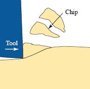
6 Orthogonal Cutting Chip formation is a localized shear deformation resulting in the failure of the workpiece material immediately ahead of the cutting edges of the tool due to the force applied to the workpiece by the cutting tool, and relative motion between the tool and the workpiece. 6
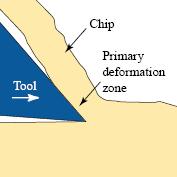
7 Orthogonal Cutting During orthogonal machining, shearing takes place along a plane making an angle, which is called the shear angle f, with the horizontal. This action transforms a volume of metal with thickness t and w (undeformed chip thickness and width, respectively) into a chip with thickness t c and width w. 7
8 Important observations during metal cutting are: Metal Cutting 1. Distortion of the workpiece and the cutting tool due to the cutting force applied by the cutting tool. 2. Generation of heat due to the work required to deform the workpiece and the chip, friction between the face of the tool and the chip, friction between the flank of the tool and the workpiece. 8

9 Temperature Distribution 9

10 Effects of Work Material Properties Strength High-strength materials require larger forces than do materials of lower strength, causing greater tool and workpiece deflections; increased friction force and heat generation, and temperature; and requirement of greater work input. On the other hand, hard and abrasive constituents such as carbides in steel accelerate tool wear. 10
11 Ductility Effects of Work Material Properties Ductility is an important factor. Highly ductile materials not only permit extensive plastic deformation of the chip during cutting, which increases work, heat generation, and temperature; but they also result in continuous chips which remain in contact longer with the tool face, thus causing more frictional heat generation. Chips of this type are severely deformed and have a characteristic curl. (Continuous chips) 11

12 Ductility Effects of Work Material Properties Brittle materials cause small segments of chips due to the brittle failure along the shear zone. Such chips are called discontinuous or segmented chips, and provide fairly good surface finish. Are also observed when cutting with: Small rake angle Large depth of cut Machining ductile materials at low cutting speed large feed 12
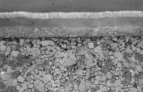
13 Continuous Chip with Built-up Edge When cutting ductile materials with a high coefficient of friction, the local high temperature and extreme pressure in the cutting zone cause the work material to adhere or weld to the cutting edge of the tool forming a builtup edge. When the chip breaks down, the broken pieces are carried away by the underside of the chip and stick on the machined surface. 13
 reducing the depth of cut; 2) increasing the cutting speed (while decreasing the depth of cut or/and feed); 3) increasing the rake")
14 Continuous Chip with Built-up Edge This type of chip is called continuous chip with built-up edge. This undesirable occurrence causes vibration, poor surface finish, and shorter tool life. Formation of built-up edge can be eliminated or minimized by 1) reducing the depth of cut; 2) increasing the cutting speed (while decreasing the depth of cut or/and feed); 3) increasing the rake angle; 4)using a cutting fluid (coolant). 14


15 Types of Chips Discontinuous (Segmented) Continuous Continuous with built-up edge 15
16 Tool Geometry The geometry of a single-point cutting tool is critical to the performance of the tool during metal removal. Important surfaces and angles on a typical HSS singlepoint cutting tool used in shaping or turning operations are: Face is surface of the tool over which the chip flows. Flank is the surface of the tool which is in contact with the workpiece. 16
17 Tool Geometry Rake angles are used to define the inclination of the face. The face is inclined backwards with respect to the cutting edge, so that the chip is directed upward from the machined surface. Relief angles are used to define the inclination of the surfaces of the tool which are in contact with the workpiece (e.g. flank). These surfaces are inclined, so that the rubbing of the tool on to the workpiece is prevented. True rake is defined as the inclination of the tool face at the cutting edge as measured in the direction of actual chip flow. 17
18 Cutting Tool Geometry - Single Point Cutting Tool 18
19 Rake Angle For cutting mild steel the best rake angle is degrees. Positive rake angle Increased strength Easy cutting Increased heat conduction capacity Reduced strength at tool neck and cutting edge Negative rake angle 19
20 Tool Geometry Small rake angles cause high compression, tool forces, and friction which result a thick, highly deformed, hot chip. Large rake angles reduce compression, the forces, and the friction resulting in a thinner, less deformed, and cooler chip. On the other hand larger positive rake angles cause reduced strength of the cutting tool due to the reduced tool section and reduced capacity to conduct heat away from the cutting edge. In order to provide greater strength at the cutting edge and better heat conductivity, zero or negative rake angles are used on sintered carbide or ceramic cutting tools. 20
21 Depth of cut Shear Plane Angle between tool face and shear plane is about 90 degrees. For the same depth of cut, increased rake angle increases the shear angle f and decreases the shear plane edge length. f f f Thus it becomes possible to remove the chip with less power. 21
 in the machine and possibly cause damage to personnel. 22")
22 Chip Breakers As a chip breaker, a groove on the tool face is employed for deflection of the chip at a sharp angle and causing it to break into short pieces that are easier to remove and are not so likely to become tangled (dolaşma, karışma) in the machine and possibly cause damage to personnel. 22


23 Chip Breakers Solid chip breakers are available in various lengths and angles to suit each metal cutting application. The adjustable chip breaker can eliminate the need for stocking various sizes of solid chip breakers. Solid chip breaker Adjustable chip breaker 23
24 Cutting Tool Materials Cutting tool materials should have: 1. Strength, 2. Toughness to resist fracture, 3. Hardness and wear resistance at high temperatures, 4. Low coefficient of friction. (5. Favorable cost.) 24
25 2. High Speed Steel (HSS) (1900) Cutting Tool Materials Typical composition of this high alloy steel is (tungsten 18%, chromium 4%, vanadium 1%). Retains its hardness at temperatures up to 600 C. Compared with tool steel, it can operate at about double the cutting speed with equal life, resulting in its name highspeed steel. HSS is widely used for drills and many types of generalpurpose milling cutters and in single-point tools used in general machining. For high-production machining it has been almost completely replaced by carbides and coated tools. 25
26 Cutting Tool Materials 3. TiN Coated High Speed Steel (HSS) (1980) Coated HSS provides significant improvements in cutting speeds, with increases of 10 to 20% being typical. In addition to hobs, gear-shaper cutters, and drills; HSS tooling coated by TiN includes reamers, taps, chasers, spade-drill blades, broaches, band saw and circular saw blades, insert tooling, form tools, end mills, and an assortment of other milling cutters. Physical vapor deposition has proved to be the most viable process for coating. 26
27 Cutting Tool Materials 4. Cemented Carbide (Sintered Carbide) (1947) Nonferrous alloys produced by powder metallurgy. The early versions, which are still widely used, had tungsten carbide as the major constituent and cobalt as a binder. Recent types of carbides utilize very fine micro particles dispersed (cemented) in the carbide structure (approx.10% TiC and TaC) for improving toughness and tool life. They can be operated at cutting speeds 200 to 500 % greater than those used for HSS, and they have replaced HSS in many processes. 27


28 Cemented Carbide Many carbide tools are made in the form of throwaway inserts, having three to eight cutting edges, and are held mechanically in tool holders. When one cutting edge becomes dull, the insert is repositioned to a new edge; when all the edges become dull, it is thrown away. 28
 tips.")
29 Cutting Tool Materials 5. Ceramic (1950s) Ceramics are made of pure aluminum oxide by powder metallurgy techniques. They can be operated at from two or three times the cutting speed of tungsten carbide, usually requiring no coolant. Usually they are in the form of disposable (throwaway) tips. Ceramics are usually as hard as carbides but are more brittle, and require more rigid tool holders and machine tools. 29
30 Cermets are best suited for finishing. Ceramic - Cermet Approximately 70 percent ceramic and 30 percent titanium carbide, are pressed into billets under extremely high pressure and temperature. After sintering, the billets are sliced to the desired tool shapes. Subsequent grinding operations for final size and edge preparation, complete the manufacturing process. 30
31 Cutting Tool Materials 6. Diamond Hardest material known. Diamond is pure carbon, and carbon has a strong affinity for iron, forming iron oxide or carbide; which results in removal of carbon, thus rapid wear of the tool during machining of ferrous workpieces. Therefore, they should only be used on non-ferrous metals. Has limited but important application in machining operations such as in boring. Diamond machining is done at high speeds with fine feeds for finishing, and produces excellent finishes. Diamond particles are used in grinding wheels. Diamond tools are used for truing the grinding wheels. 31
 bonded to a carbide base.")

32 Diamond - Polycrystalline Diamond Some diamond cutting tools are made of a diamond crystal compaction (many small crystals pressed together) bonded to a carbide base. These diamond cutting tools should only be used for light finishing cuts of precision surfaces. Feeds should be very light and speeds are usually high. Rigidity in the machine tool and the setup is very critical because of the extreme hardness and brittleness of diamond. 32
.")
33 7. Cubic Boron Nitride (CBN) (1965s) Man-made tool material. Similar to diamond in its polycrystalline structure and is also bonded to a carbide base. Cutting Tool Materials Hardest material known other than diamond. Retains it hardness at elevated temperatures (~ 1000 C). Still, CBN should mainly be considered as a finishing tool material because of its extreme hardness and brittleness. Can be used to machine hard aerospace materials. 33
34 8. Coated Carbide (1972) Cutting Tool Materials A tough, shock-resistant carbide tool is coated with a thin, hard, crater resistant surface material. TiC-coated tools have two or three times the wear resistance of the best uncoated tool with the same breakage resistance. This results in 50 to 100 % increase in the speed for the same tool life. Ceramic (Al 2 O 3 )-coating permits 90 % speed increase in machining of steel. Gives excellent crater wear resistance. 34

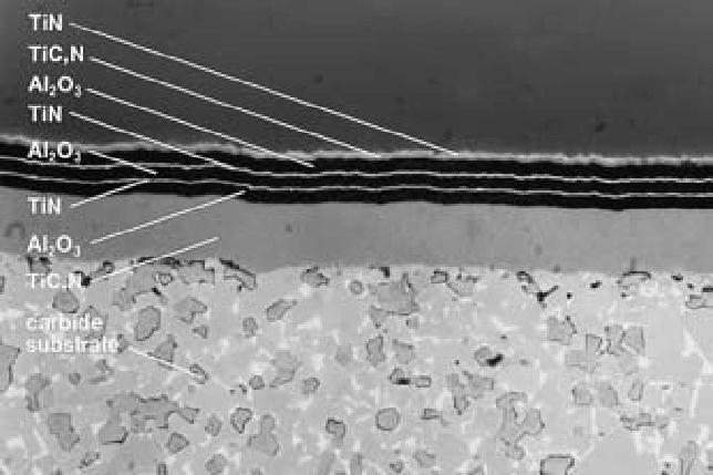
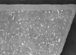
35 Coated Carbide 35


36 Hardness - Strength - Toughness 36
37 Cutting Tool Materials FIGURE 21-1 Improvements in cutting tool materials have led to significant increases in cutting speeds (and productivity) over the years. 37
38 *** MACHINING/cutting tool materials (SME/Wiley s video)*** 38
39 Tool Life and Tool Failure A tool may be said to reach end of its life when a further wear causes one, some or all of the followings. 1. Loss of dimensional accuracy of the workpiece, 2. Excessive surface roughness on the workpiece, 3. Increased power requirement of the machine tool, 4. Physical loss of the cutting edge of the cutting tool. The cutting time accumulated before failure is termed as tool life. 39


40 Tool Wear Crater Tool wear, which is increased by high temperatures which cause the tool material to loose its hardness and thus make it more subjected to wear, occurs mainly in two areas. 1. On tool face, causing formation of craters due to the severe abrasion between the chip and the tool face, being more common on HSS tools in machining ductile materials. 40


41 Tool Wear 2. On the flank below the cutting edge, resulting from contact with the abrasive machined surface both in rough and finishing operations. For carbide and ceramic tools flank wear is the most common type of wear. 41

 is usually observed after a considerable cutting time, nose wear appears when the tool has already exhibited land and/or crater")
42 Edge wear Tool Wear Nose wear Tool wear is also observed at the edge and the nose of the tool areas. 3. Edge wear occurs on the clearance face of the tool and is mainly caused by the rubbing of the newly machined workpiece surface on the contact area of the tool edge. This type of wear occurs on all tools while cutting any type of work material. 4. Nose wear (corner wear) is usually observed after a considerable cutting time, nose wear appears when the tool has already exhibited land and/or crater wear. Wear on the nose of the cutting edge usually affects the quality of the surface finish on the workpiece. 42
43 Tool Wear 43
, the excessive cutting force may cause tool failure.")
44 Tool Wear Flank wear appears in the form of so-called wear land and is measured by the width of this wear land, VB. Flank wear affects to the great extend the mechanics of cutting. Cutting forces increase significantly with flank wear. If the amount of flank wear exceeds some critical value (VB > 0.5~0.6 mm), the excessive cutting force may cause tool failure. 44
45 Tool Wear Corner wear (nose wear) actually shortens the cutting tool, thus increasing gradually the dimension of machined surface and introducing a significant dimensional error in machining, which can reach values of about 0.03~0.05 mm. 45
46 Tool Wear Tool wear is affected by; 1) workpiece material properties, 2) cutting force-controlled by proper selection of feed and depth of cut. 3) Temperature-related to cutting speed (as cutting speed increase, the temperature of the cutting zone increases which causes a loss in tool properties and decreased tool life). 46
47 Tool Wear FIGURE Typical tool wear curves for flank wear at different velocities. The initial wear is very fast, then it evens out to a more gradual pattern until the limit is reached; after that, the wear substantially increases. 47
 Frederick W.")
48 A simple and easy-to-use analytical expression which gives the relationship between the cutting speed and the tool life is given below. This expression is called Taylor's Equation. V T n = C V - Cutting speed in m/min T - Tool life in minutes C - Cutting speed for 1 minute tool life Taylor's Equation n - Exponent (Slope of the cutting speed versus tool life plot) Frederick W. Taylor ( ) 48
49 Taylor's Equation C and n are found by conducting experiments at different cutting speeds and recording the tool life. When plotted on log-log scale, cutting speed versus tool life relationship becomes a straight line, so that values of C and n can be determined easily. V T n = C 49
50 C - Cutting speed for 1 minute tool life Depends on all input parameters, including feed. n - Exponent (Slope of the cutting speed versus tool life plot) Depends mostly on cutting tool material, but is effected by work material, cutting conditions, and environment to 0.16 for HSS 0.25 for uncoated carbides, 0.30 for TiC-coated insert 0.40 for ceramic coated inserts. Taylor's Equation = > n increases with increasing tool material quality 50
51 Cutting Fluids (Coolants) Coolants are used to decrease tool operating temperature and improve cutting performance. A good cutting fluid should act as a lubricant as well as removing the heat (coolant) from the cutting zone. Water is a good coolant, but is a poor lubricant and presents corrosion (rust) hazard. On the other hand, oil is a good lubricant but is less effective in cooling. In practice, emulsion combinations of oil and water or wax and water are used as cutting fluids. 51
52 Cutting Fluids (Coolants) Advantages Gained by Using Cutting Fluids 1. Tool life is increased. 2. Surface finish of the workpiece is improved. 3. Built-up edge formation is prevented. 4. Power consumed by the machine tool is reduced. 5. Corrosion hazard is reduced. 6. Chips are washed away and the cutting zone is kept clear. 52
Workshop Practice TA 102 Lec 6 & 7 :Theory of Metal Cutting. By Prof.A.Chandrashekhar
 Workshop Practice TA 102 Lec 6 & 7 :Theory of Metal Cutting By Prof.A.Chandrashekhar Theory of Metal cutting INTRODUCTION: The process of manufacturing a component by removing the unwanted material using
THEORY OF METAL CUTTING
 THEORY OF METAL CUTTING INTRODUCTION Overview of Machining Technology Mechanism of chip formation Orthogonal and Oblique cutting Single Point and Multipoint Cutting Tools Machining forces - Merchant s
Manufacturing Processes(IM 212)
") Arab Academy for Science, Technology, and Maritime Transport Manufacturing Processes(IM 212) Department of Industrial & Management Engineering College of Engineering and Technology Lecture 1 : Introduction
Arab Academy for Science, Technology, and Maritime Transport Manufacturing Processes(IM 212) Department of Industrial & Management Engineering College of Engineering and Technology Lecture 1 : Introduction
Metal Cutting Processes 1 - Turning
 You are here: Home > Handout > Metal Cutting Processes 1 - Turning Metal Cutting Processes 1 - Turning Contents 1. Introduction 2. Center Lathe 3. Cutting Tools 4. Basic Matel Cutting Theory 5. Tool Angles
MANUFACTURING TECHNOLOGY
 MANUFACTURING TECHNOLOGY UNIT III THEORY OF METAL CUTTING Broad classification of Engineering Manufacturing Processes. It is extremely difficult to tell the exact number of various manufacturing processes
Materials & Processes in Manufacturing
 2003 Bill Young Materials & Processes in Manufacturing ME 151 Chapter 21 Fundamentals of Chip Type Machining Processes 1 Materials Processing 2003 Bill Young 2 Introduction Machining is the process of
TOOL WEAR AND TOOL LIFE
 TOOL WEAR AND TOOL LIFE CONTENTS 4.1 Tool wear During the cutting operation, the cutting edge is stressed mechanically and thermally until it becomes completely blunt and unable to cut, 100 % wear occurs
Abrasive Machining Processes. N. Sinha, Mechanical Engineering Department, IIT Kanpur
 Abrasive Machining Processes N. Sinha, Mechanical Engineering Department, IIT Kanpur Introduction Abrasive machining involves material removal by the action of hard, abrasive particles. The use of abrasives
Chapter 24 Machining Processes Used to Produce Various Shapes.
 Chapter 24 Machining Processes Used to Produce Various Shapes. 24.1 Introduction In addition to parts with various external or internal round profiles, machining operations can produce many other parts
CHAPTER 23 Machining Processes Used to Produce Various Shapes Kalpakjian Schmid Manufacturing Engineering and Technology 2001 Prentice-Hall Page 23-1
 CHAPTER 23 Machining Processes Used to Produce Various Shapes Manufacturing Engineering and Technology 2001 Prentice-Hall Page 23-1 Examples of Parts Produced Using the Machining Processes in the Chapter
 VALLIAMMAI ENGINEERING COLLEGE DEPARTMENT OF MECHANICAL ENGINEERING QUESTION BANK ME6402 MANUFACTURING TECHNOLOGY II UNIT-I PART A 1. List the various metal removal processes? (BT1) 2. Explain how chip
Lecture 18. Chapter 24 Milling, Sawing, and Filing; Gear Manufacturing (cont.) Planing
 Planing") Lecture 18 Chapter 24 Milling, Sawing, and Filing; Gear Manufacturing (cont.) Planing For production of: Flat surfaces Grooves Notches Performed on long (on average 10 m) workpieces Workpiece moves / Tool
Lecture 18 Chapter 24 Milling, Sawing, and Filing; Gear Manufacturing (cont.) Planing For production of: Flat surfaces Grooves Notches Performed on long (on average 10 m) workpieces Workpiece moves / Tool
AUTOMATED MACHINE TOOLS & CUTTING TOOLS
 CAD/CAM COURSE TOPIC OF DISCUSSION AUTOMATED MACHINE TOOLS & CUTTING TOOLS 1 CNC systems are used in a number of manufacturing processes including machining, forming, and fabrication Forming & fabrication
 DEPARTMENT OF MECHANICAL ENGINEERING QUESTION BANK ME6402 MANUFACTURING TECHNOLOGY II UNIT I PART A 1. List the various metal removal processes? 2. How chip formation occurs in metal cutting? 3. What is
Common Machining Processes
 Common Machining Processes FIGURE 8.1 Some examples of common machining processes. Orthogonal Cutting FIGURE 8.2 Schematic illustration of a two-dimensional cutting process, or orthogonal cutting. (a)
Materials Removal Processes (Machining)
") Chapter Six Materials Removal Processes (Machining) 6.1 Theory of Material Removal Processes 6.1.1 Machining Definition Machining is a manufacturing process in which a cutting tool is used to remove excess
Chapter Six Materials Removal Processes (Machining) 6.1 Theory of Material Removal Processes 6.1.1 Machining Definition Machining is a manufacturing process in which a cutting tool is used to remove excess
Design for machining
 Multiple choice questions Design for machining 1) Which one of the following process is not a machining process? A) Planing B) Boring C) Turning D) Forging 2) The angle made between the rake face of a
GENERAL MACHINING PRACTICE FOR CMI ELECTROMAGNETIC IRON
 GENERAL MACHINING PRACTICE FOR CMI ELECTROMAGNETIC IRON Electromagnetic Iron can be readily machined when proper tool angles are used. Tools should be ground to more acute cutting edge angles than are
New. Products2013.
 T u n g a l o y www.tungaloy.com Company Overview Providing Complete Tooling Solutions for the Metal Removal and Industrial Product Sectors TUNGALOY is one of the world s leading manufacturers of carbide
Machining Processes Used to Produce Various Shapes. Dr. Mohammad Abuhaiba
 Machining Processes Used to Produce Various Shapes 1 Homework Assignment Due Wensday 28/4/2010 1. Show that the distance lc in slab milling is approximately equal to for situations where D>>d. (see Figure
INDEXABLE BORING BAR AND INSERTS FLAT TOP, CHIP CONTROL, CBN, AND PCD
 INDEXABLE BORING BAR AND S FLAT TOP, CHIP CONTROL,, AND 80 Diamond.156 IC R.156.040 80 DIAMOND FLAT TOP 80 DIAMOND CHIP CONTROL AT6+ 0.003 ACD5031 ACD5031E AT6+ 0.007 ACD5071 ACD5071E AT6+ 0.015 ACD5151
Design for machining
 Design for machining Machining processes are material removal processes which are a family of shaping operation in which excess or undesired material is removed from the work piece finally remaining with
MANUFACTURING TECHNOLOGY
 MANUFACTURING TECHNOLOGY UNIT IV SURFACE FINISHING PROCESS Grinding Grinding is the most common form of abrasive machining. It is a material cutting process which engages an abrasive tool whose cutting
FOR IMMEDIATE RELEASE
 FOR IMMEDIATE RELEASE Seco Tools AB Björnbacksvägen 2 73782 Fagersta Sweden Bettina PALMEN Phone: +49 211 2401-313 E-mail: bettina.palmen@secotools.com www.secotools.com Tribological wear analysis Fagersta,
Grinding. Vipin K Sharma
 Grinding Grinding It is a material cutting process which engages an abrasive tool(in the form of a wheel) whose cutting elements are grains of abrasive material known as grit. These grits are characterized
SAMPLE BOOK TWO AND MACHINING LEARNER RESOURCE MEM05F&MB2/1 FIRST EDITION
 AND MACHINING BOOK TWO LEARNER RESOURCE MEM05 Training Package Units: MEM07005B, MEM07006B, MEM07007B, MEM07008B, MEM07021B, MEM12001B, MEM12006B, MEM12023A MEM05F&MB2/1 FIRST EDITION Publishing details:
UNIT I THEORY OF METAL CUTTING
 THEORY OF METAL CUTTING & TOOL DESIGN UNIT I THEORY OF METAL CUTTING INTRODUCTION In an industry, metal components are made into different shapes and dimensions by using various metal working processes.
A Pictorial Odyssey. Grinding: An examination of the grinding process through the lens of an electron microscope. By Dr.
 Grinding: A Pictorial Odyssey A FEBRUARY 2009 / VOLUME 61 / ISSUE 2 By Dr. Jeffrey Badger An examination of the grinding process through the lens of an electron microscope. picture is worth a thousand
Chapter 25. Other Machining Processes. Materials Processing. MET Manufacturing Processes. Shaping Planing Broaching Sawing Filing
 MET 33800 Manufacturing Processes Chapter 25 Other Machining Processes Before you begin: Turn on the sound on your computer. There is audio to accompany this presentation. Other Machining Processes Shaping
Lecture 15. Chapter 23 Machining Processes Used to Produce Round Shapes. Turning
 Lecture 15 Chapter 23 Machining Processes Used to Produce Round Shapes Turning Turning part is rotating while it is being machined Typically performed on a lathe Turning produces straight, conical, curved,
Hard turning of interrupted surfaces using CBN tools
 journal of materials processing technology 195 (2008) 275 281 journal homepage: www.elsevier.com/locate/jmatprotec Hard turning of interrupted surfaces using CBN tools Anselmo Eduardo Diniz, Adilson José
Contents 1. Cutting and Cutting Tools 2. Processing by End Mills 3. Cutting Action and Phenomena during Cutting
 Basics of End Mills Contents 1. Cutting and Cutting Tools 2. Processing by End Mills 3. Cutting Action and Phenomena during Cutting Contents 1. Cutting and Cutting Tools 2. Processing by End Mills 3. Cutting
Band Machining. Chapter 20
 Chapter 20 Band Machining LEARNING OBJECTIVES After studying this chapter, students will be able to: Describe how a band machine operates. Explain the advantages of band machining. Select the proper blade
The role of inclination angle, λ on the direction of chip flow is schematically shown in figure which visualizes that,
 EXPERIMENT NO. 1 Aim: To study of Orthogonal & Oblique Cutting on a Lathe. Experimental set up.: Lathe Machine Theoretical concept: It is appears from the diagram in the following figure that while turning
Roll No. :.. Invigilator s Signature :.. CS/B.Tech (ME)/SEM-5/ME-504/ TECHNOLOGY OF MACHINING. Time Allotted : 3 Hours Full Marks : 70
/SEM-5/ME-504/ TECHNOLOGY OF MACHINING. Time Allotted : 3 Hours Full Marks : 70") Name : Roll No. :.. Invigilator s Signature :.. CS/B.Tech (ME)/SEM-5/ME-504/2009-10 2009 TECHNOLOGY OF MACHINING Time Allotted : 3 Hours Full Marks : 70 The figures in the margin indicate full marks. Candidates
Name : Roll No. :.. Invigilator s Signature :.. CS/B.Tech (ME)/SEM-5/ME-504/2009-10 2009 TECHNOLOGY OF MACHINING Time Allotted : 3 Hours Full Marks : 70 The figures in the margin indicate full marks. Candidates
Review of Various Machining Processes
 Review of Various Machining Processes Digambar O. Jumale 1, Akshay V kharat 2, Akash Tekale 3, Yogesh Sapkal 4,Vinay K. Ghusalkar 5 Department of mechanical engg. 1, 2, 3, 4,5 1, 2, 3, 4,5, PLITMS Buldana
Metal Cutting - 5. Content. Milling Characteristics. Parts made by milling Example of Part Produced on a CNC Milling Machine 7.
 Content Metal Cutting - 5 Assoc Prof Zainal Abidin Ahmad Dept. of Manufacturing & Industrial Engineering Faculty of Mechanical Engineering Universiti Teknologi Malaysia 7. MILLING Introduction Horizontal
Applied Machining Technology
 Applied Machining Technology Heinz Tschätsch Applied Machining Technology 1 C Author Prof. Dr.-Ing. Heinz Tschätsch Paul-Gerhard-Str. 25 01309 Dresden Germany Translator Dr.-Ing. Anette Reichelt Technik
GRINDING. quakerchem.com
 OVERVIEW Metal removal fluids (MRF) are used for both machining and grinding applications. As was discussed in the basic training, both applications are similar in that there is an interface between the
Sharpening Twist Drills. Relief Grinding of the Tool Flanks.
 TOOL WEAR 933 Tool Wear Metal cutting tools wear constantly when they are being used. A normal amount of wear should not be a cause for concern until the size of the worn region has reached the point where
Cutting with broach. You can find here some notices about broaching operation. Fig.N 1
 Cutting with broach You can find here some notices about broaching operation. Fig.N 1 Amount of cut per tooth This parameter depends on many characteristic of broaching operation like: Material of the
Tool and Die Maker Level 2
 Level 2 B2 Read and Interpret Drawings II Duration: 32 hours 32 hours 0 hours This unit of instruction introduces the Tool and Die Maker Apprentice with the knowledge and skills necessary to read and interpret
11/15/2009. There are three factors that make up the cutting conditions: cutting speed depth of cut feed rate
 s Geometry & Milling Processes There are three factors that make up the cutting conditions: cutting speed depth of cut feed rate All three of these will be discussed in later lessons What is a cutting
FUNDAMENTAL MANUFACTURING PROCESSES Plastics Machining & Assembly NARRATION (VO): NARRATION (VO): NARRATION (VO): INCLUDING: METALS,
: NARRATION (VO): NARRATION (VO): INCLUDING: METALS,") Copyright 2002 Society of Manufacturing Engineers --- 1 --- FUNDAMENTAL MANUFACTURING PROCESSES Plastics Machining & Assembly SCENE 1. CG: Plastics Machining white text centered on black SCENE 2. tape
Copyright 2002 Society of Manufacturing Engineers --- 1 --- FUNDAMENTAL MANUFACTURING PROCESSES Plastics Machining & Assembly SCENE 1. CG: Plastics Machining white text centered on black SCENE 2. tape
Sawing Basics V63WCWO3. Operator Variables That Aid Sawing Performance
 Sawing Basics V63WCWO3 Operator Variables That Aid Sawing Performance When making blade recommendations, there are a few questions we need to answer: Which blade do we use? Which tooth pitch do we use?
MLR Institute of Technology
 MLR Institute of Technology Dundigal, Quthbullapur (M), Hyderabad 500 043 MECHANICAL ENGINEERING MACHINE TOOLS OBJECTIVE QUESTIONS UNIT - I 1. A built up-edge is formed while machining [ B ] (Sep-2011,
Tool Wear Performance of CVD-Insert during Machining of Ti-6%Al-4%V ELI at High Cutting Speed
 Key Engineering Materials Vol. 443 (2010) pp 371-375 (2010) Trans Tech Publications, Switzerland doi:10.4028/www.scientific.net/kem.443.371 Tool Wear Performance of CVD-Insert during Machining of Ti-6%Al-4%V
Mission Statement. 2005, Manchester Tool Company. All rights reserved.
 Mission Statement Manchester Tool Company shall provide tooling systems to the metal cutting and similar industries, specializing in cutoff, grooving and complimentary niche products. We are dedicated
Investigation And Optimization Of Various Machining Parameters Affecting The Effectiveness Of Turning: A Review
 Investigation And Optimization Of Various Machining Parameters Affecting The Effectiveness Of Turning: A Review 1 S B Chikalthankar Assistant Professor Department of Mechanical Engineering, Government
CHAPTER-1 INTRODUCTION. S.No. Name of the Sub-Title Page No. 1.1 Introduction Manufacturing System Metal Cutting 4
 1 CHAPTER-1 INTRODUCTION S.No. Name of the Sub-Title Page No. 1.1 Introduction 2 1.2 Manufacturing System 3 1.3 Metal Cutting 4 1.3.1 Independent Input Variables 4 1.3.2 Dependent Variables 6 1.3.3 Relations
ROOP LAL Unit-6 Lathe (Turning) Mechanical Engineering Department
 Mechanical Engineering Department") Notes: Lathe (Turning) Basic Mechanical Engineering (Part B) 1 Introduction: In previous Lecture 2, we have seen that with the help of forging and casting processes, we can manufacture machine parts of
Notes: Lathe (Turning) Basic Mechanical Engineering (Part B) 1 Introduction: In previous Lecture 2, we have seen that with the help of forging and casting processes, we can manufacture machine parts of
MACHINING HOT-ROLLED STEEL PLATES AND COILS
 www.ruukki.com MACHINING HOT-ROLLED STEEL PLATES AND COILS This brochure compiles information on machining our hot rolled steel products, including the following methods: drilling thread cutting sawing
DIAMOND TOOLING FOR COMPOSITE MATERIALS P.B.S. DIAMOND TOOLING PCD TOOLING FLEXIBLE DIAMOND TOOLING
 DIAMOND FOR COMPOSITE MATERIALS P.B.S. DIAMOND PCD FLEXIBLE DIAMOND P.B.S. DIAMOND First patented by Abrasive Technology in 1975, this original brazed bonding process chemically bonds superabrasive crystals
Grade/Chip breaker. Contents. Grades. Chip breakers A02 A03 A04. Korloy grades system Grade selection system The feature of korloy grades A06 A08 A09
 Grade/Chip breaker Contents Korloy grades system Grade selection system The feature of korloy grades A02 A03 A04 For For For A06 A08 A09 >>> /Chipbreakers Korloy grades system Uncoated P For steel ST05
Chapter 26 Abrasive Machining Processes. Materials Processing ABRASIVE MACHINING 10/11/2014. MET Manufacturing Processes
 MET 33800 Manufacturing Processes Chapter 26 Abrasive Machining Processes Before you begin: Turn on the sound on your computer. There is audio to accompany this presentation. Materials Processing Chapters
DIAMOND TOOLING FOR COMPOSITE MATERIALS P.B.S. DIAMOND TOOLING PCD TOOLING FLEXIBLE DIAMOND TOOLING
 DIAMOND TOOLING FOR COMPOSITE MATERIALS P.B.S. DIAMOND TOOLING PCD TOOLING FLEXIBLE DIAMOND TOOLING Abrasive Technology s diamond tooling is perfectly suited for composites as it provides comprehensive
Understanding the Wire EDM Process
 5 Understanding the Wire EDM Process 81 Accuracy and Tolerances Wire EDM is extremely accurate. Many machines move in increments of 40 millionths of an inch (.00004") (.001 mm), some in 10 millionths of
Research on hardened steel turning with superhard tool material
 Research on hardened steel turning with superhard tool material M.Sc. Eng. Jakub Siwiec Supervisor: D.S. Eng. Wojciech Zebala Abstract The paper presents results of research on hardened steel turning with
New Leader of Carbide & Diamond Tools
 New Leader of Carbide & Diamond Tools www.jdtools.co.kr Special tools are strength! Dear Customers, We have been very much grateful of our all customers who love JD TOOLS. We, JD TOOLS is the leading supplier
NON-TRADITIONAL MACHINING PROCESSES ULTRASONIC, ELECTRO-DISCHARGE MACHINING (EDM), ELECTRO-CHEMICAL MACHINING (ECM)
, ELECTRO-CHEMICAL MACHINING (ECM)") NON-TRADITIONAL MACHINING PROCESSES ULTRASONIC, ELECTRO-DISCHARGE MACHINING (EDM), ELECTRO-CHEMICAL MACHINING (ECM) A machining process is called non-traditional if its material removal mechanism is basically
NON-TRADITIONAL MACHINING PROCESSES ULTRASONIC, ELECTRO-DISCHARGE MACHINING (EDM), ELECTRO-CHEMICAL MACHINING (ECM) A machining process is called non-traditional if its material removal mechanism is basically
8029 S 200th St. Kent, WA USA Ph: Fax:
 8029 S 200th St. Kent, WA 98032 USA Ph: 253-872-7050 Fax: 253-395-0230 1 GENERAL INFORMATION Rottler CBN and PCD Inserts are laser marked with our part number on one side. On single sided inserts, the
Your Specials Are Our Standards TM
 09/2010 TM Your Specials Are Our Standards TM 400 New Tools Inside! See Inside Cover For Details ALL TOOLS IN STOCK! SAME DAY SHIPPING! Harvey Tool Company, LLC 319 Newburyport Turnpike Rowley, MA 01969
Makrolon Solid Polycarbonate Sheets
 1. General remarks Tools sheets can be machined using the standard tools commonly used for metal and woodworking. We recommend carbide-tipped tools. Above all, it is important to use sharp cutting tools
SURFACE LAYER PROPERTIES IN DRY TURNING OF C45 STEEL
 SURFACE LAYER PROPERTIES IN DRY TURNING OF C STEEL Tadeusz Leppert University of Technology and Life Sciences ul. Kordeckiego, - Bydgoszcz, Poland e-mail: tleppert@utp.edu.pl Abstract In machining operations
Cold Saw Blade Basics
 Cold Saw Blade Basics 01/2018 Scotchman Industries Inc. 180 US-14 Philip, SD 57567 USA Phone 800.843.8844 - Fax 800.843.2499 www.scotchman.com info@scotchman.com THE COLD SAW BLADE MATERIAL Most Cold Saw
Think efficiency, Think HSS MILLING
 Think efficiency, Think HSS MILLING SUMMARY MILLING TOOLS 2 Zoom on a milling cutter 3 Which HSS for maximum efficiency? 4 Coatings for the best performance 5 Vocabulary 6 Choose the right design 7 Select
Wire Drawing 7.1 Introduction: stock size
 Wire Drawing 7.1 Introduction: In drawing, the cross section of a long rod or wire is reduced or changed by pulling (hence the term drawing) it through a die called a draw die (Fig. 7.1). Thus, the difference
ME 6402 MANUFACTURING TECHNOLOGY II
 ME 6402 MANUFACTURING TECHNOLOGY II L T P C 3 0 0 3 OBJECTIVE To understand the concept and basic mechanics of metal cutting, working of standard machine tools such as lathe, shaping and allied machines,
w w w. s ulcorte. com.br
 w w w. s ulcorte. com.br HEADQUARTER CAXIAS DO SUL With more than 20 years tradition in the metalworking industry, Sul Corte is the leader company in the manufacturing and marketing of Circular Saw Blades,
Roughing vs. finishing
 Finishing methods Roughing vs. finishing Roughing removing material as fast as possible, without special demands on surface and low demand on precision high Q, high IT, high Ra Finishing making final surface
Effect of Rake Angles on Cutting Forces for A Single Point Cutting Tool
 Effect of Rake Angles on Cutting Forces for A Single Point Cutting Tool Pradeesh A. R. 1 ; Mubeer M. P 2 ; Nandakishore B 3 ; Muhammed Ansar K 4 ; Mohammed Manzoor T. K 5 ; Muhammed Raees M. U 6 1Asst.
External Turning. Outline Review of Turning. Cutters for Turning Centers
 Outline Review of Turning External Turning 3 External Turning Parameters Cutting Tools Inserts Toolholders Machining Operations Roughing Finishing General Recommendations Turning Calculations Machining
QUALITY CERTIFICATE. being prepared by me and it meets the knowledge requirement of the university curriculum.
 A Course Material on Manufacturing Technology - II By Mr. M. IYER. M.E. ASSISTANT PROFESSOR DEPARTMENT OF MECHANICAL ENGINEERING SASURIE COLLEGE OF ENGINEERING VIJAYAMANGALAM 638 056 1 QUALITY CERTIFICATE
APRIL 2009 / NEW-100 / PAGE 1 OF 13
 APRIL 2009 / NEW-100 / PAGE 1 OF 13 The standard UNIDEX line covers reaming applications from 5/16 to 1 1/4 diameter. The single indexable blade and high wear resistant carbide or cermet pads provide a
Table of Contents. Production Options 3. Suggested Tooling 4. Special Considerations 4. Sawing 4. Holding 5. Turning 5. Milling 6.
 Table of Contents Production Options 3 Suggested Tooling 4 Special Considerations 4 Sawing 4 Holding 5 Turning 5 Milling 6 Drilling 6 Threading 7 Grinding 7 Buffing and Polishing 8 Deburring 8 Lapping
Chapter 23: Machining Processes: Turning and Hole Making
 Manufacturing Engineering Technology in SI Units, 6 th Edition Chapter 23: Machining Processes: Turning and Hole Making Chapter Outline 1. Introduction 2. The Turning Process 3. Lathes and Lathe Operations
National Conference on Advances in Mechanical Engineering Science (NCAMES-2016)
") Effects of Cutting Fluids and Machining Parameter on Turning of Mild Steel K.G Sathisha 1, V.Lokesh 2, Priyesh 3, 1,2 Assistant professor, Department of Mechanical Engineering, Srinivas Institute of Technology,
Effects of Cutting Fluids and Machining Parameter on Turning of Mild Steel K.G Sathisha 1, V.Lokesh 2, Priyesh 3, 1,2 Assistant professor, Department of Mechanical Engineering, Srinivas Institute of Technology,
LANDMARK UNIVERSITY, OMU-ARAN
 LANDMARK UNIVERSITY, OMU-ARAN LECTURE NOTE: DRILLING. COLLEGE: COLLEGE OF SCIENCE AND ENGINEERING DEPARTMENT: MECHANICAL ENGINEERING PROGRAMME: MECHANICAL ENGINEERING ENGR. ALIYU, S.J Course code: MCE
EFFECT OF CUTTING PARAMETERS ON THE TOOL WEAR AND TOOL LIFE IN DRY ENVIRONMENT A REVIEW
 EFFECT OF CUTTING PARAMETERS ON THE TOOL WEAR AND TOOL LIFE IN DRY ENVIRONMENT A REVIEW NILESH D. JALAN [1], V.N. KSHIRSAGAR [2] [1] B.E. (pursuing), Department of Mechanical Engineering, G.H. Raisoni
PRODUCT INFORMATION CBN-SXR CBN-LN-SXR CBN-SXB CBN-LN-SXB. CBN End Mill Series
 PRODUCT INFORMATION CBN-LN-SXR CBN-LN-SXB CBN End Mill Series The helical flutes are changing the CBN end mills! Highly Appealing OSG CBN End Mill Series Are you bothered by these issues? The work material
TUBE AND SHEET DRILLS
 TUBE AND SHEET DRILLS 03 Tube and sheet drills The flutes of the RUKO high performance tube and sheet drills are BN ground from the solid hardened form. Because BN (cubical boron nitride) is a much harder
Special reamers. Figure N 1 Reamer with descending cutting edges in carbide (Cerin)
") Special reamers There is a wide category of special reamers, ie non-standard, that are suitable to address particular problems encountered in the finishing holes, both for maintenance of individual pieces
Special reamers There is a wide category of special reamers, ie non-standard, that are suitable to address particular problems encountered in the finishing holes, both for maintenance of individual pieces
TOOLS NEWS B218G. Hydro-Clamp Type Valve Finisher HVF. New Product. Series. Drastically shortened time and reduced costs!
 TOOLS NEWS Hydro-Clamp Type Valve Finisher HVF Series B218G New Product Drastically shortened time and reduced costs! Cooperated with Hydro-Clamp Type Valve Finisher HVF Series Greatly Reduced Costs The
A TRADITION OF QUALITY SINCE 1966 DIAMOND AND CBN WHEELS
 A TRADITION OF QUALITY SINCE 1966 DIAMOND AND CBN WHEELS POLTAVA DIAMOND TOOLS has been manufacturing top-quality diamond tools for the machine building, glass, electronic and woodworking industries since
Elimination of Honing Stick Mark in Rack Tube B.Parthiban1 1, N.Arul Kumar 2, K.Gowtham Kumar 3, P.Karthic 4, R.Logesh Kumar 5
 Elimination of Honing Stick Mark in Rack Tube B.Parthiban1 1, N.Arul Kumar 2, K.Gowtham Kumar 3, P.Karthic 4, R.Logesh Kumar 5 Assistant Professor, Dept. of Mechanical Engineering, Jay Shriram Group of
High-Efficiency Cutting of Super-Heat-Resistant Alloy
 12 High-Efficiency Cutting of Super-Heat-Resistant Alloy Keiichi Yamamoto *1 Motofumi Kuroda *1 Hidefumi Omokawa *1 Katsutoshi Itakura *2 Inconel 718, a super-heat-resisting alloy, is difficult to cut,
Sheet Metal Forming. Part 1
 Sheet Metal Forming Part 1 Sheet Metal Forming For products with versatile shapes and lightweight Dates to 5000 B.C. Products include metal desks, file cabinets, appliances, car bodies, beverage cans Common
DEPARTMENT OF MECHANICAL ENGINEERING
 SCSVMV UNIVERSITY DEPARTMENT OF MECHANICAL ENGINEERING SUBJECT NAME : SUBJECT CODE : MANUFACTURING TECHNOLOGY-II EBM4DT055 QUESTION BANK UNIT-1 1. What is Grinding? 2. Briefly classify the Grinding Process.
CoroMill. All solutions at a glance
 CoroMill All solutions at a glance CoroMill Product overview Milling grades according to groups Shoulder milling CoroMill 316 CoroMill 490 CoroMill 790 Long edge cutter Insert size Max. cutting depth a
Typical Parts Made with These Processes
 Turning Typical Parts Made with These Processes Machine Components Engine Blocks and Heads Parts with Complex Shapes Parts with Close Tolerances Externally and Internally Threaded Parts Products and Parts
Machining Processes IME 240
 Machining Processes IME 240 Material Removal Processes Machining is the broad term used to describe removal of material from a workpiece Includes Cutting, Abrasive Processes (grinding), Advanced Machining
Router Section 2018 Master Catalog
 Router Section 2018 Master Catalog For more than 95 years, M.A. Ford has been at the cutting edge of tooling design and manufacturing and has developed an enviable global reputation for performance and
Trade of Toolmaking. Module 3: Milling Unit 9: Precision Vee Block Assembly Phase 2. Published by. Trade of Toolmaking Phase 2 Module 3 Unit 9
 Trade of Toolmaking Module 3: Milling Unit 9: Precision Vee Block Assembly Phase 2 Published by SOLAS 2014 Unit 9 1 Table of Contents Document Release History... 3 Unit Objective... 4 Introduction... 4
Manufacturing Science-II (EME-503)
") Time: 1 Hour B.Tech. [SEM V (ME-5 All Groups)] QUIZ TEST-1 Manufacturing Science-II ` Max. Marks: 30 Note: Attempt all the questions Q1) How metal is removed in metal cutting? Explain by giving any simple
Time: 1 Hour B.Tech. [SEM V (ME-5 All Groups)] QUIZ TEST-1 Manufacturing Science-II ` Max. Marks: 30 Note: Attempt all the questions Q1) How metal is removed in metal cutting? Explain by giving any simple
Review of Effect of Tool Geometry Variation on Finish Turning and Improving Cutting Tool Life
 International Conference of Advance Research and Innovation (-2014) Review of Effect of Tool Geometry Variation on Finish Turning and Improving Cutting Tool Life Abhishek Kumar *, Arun Singh, Ranganath
1
 www.icwahelpn.co.in 1 Operation Management Objective Type Question s and Answer s 1. Fill up the blanks: 1. Intension of modern industries is to create appropriate number of useful at reasonable price.
Insert Inch Overview. Insert Overview
 Insert Overview The Inserts Millstar inserts are fully ground precision inserts for better chip control, faster metal removal and higher surface accuracies. They are far more accurate than pressed and
Twist Drills for Woodworkers. Standard twist drills and two methods of sharpening 10 January 2015 Marc Pohm
 Twist Drills for Woodworkers Standard twist drills and two methods of sharpening 10 January 2015 Marc Pohm Twist Drills for Woodworking Topics that will be covered: Coatings Steel Types Drill Points Drill
Reamer Basics. Fixed Reamers The reamer size is fixed and any size reduction due to wear or sharpening cannot be reclaimed
 1 Reamer Basics Reamers are available in a variety of types, materials, flute styles and sizes The typical reamer is a rotary cutting tools designed to machine a previously formed hole to an exact diameter
Drawing. Fig. 1 Drawing
 Drawing Drawing is a metalworking process which uses tensile forces to stretch metal. It is broken up into two types: sheet metal drawing and wire, bar, and tube drawing. The specific definition for sheet