Design Methodologies. Digital Integrated Circuits A Design Perspective. Jan M. Rabaey Anantha Chandrakasan Borivoje Nikolic.
|
|
|
- Byron Barton
- 5 years ago
- Views:
Transcription
1 Digital Integrated Circuits A Design Perspective Jan M. Rabaey Anantha Chandrakasan Borivoje Nikolic Design Methodologies December 10, 2002
2 L o g i c T r a n s i s t o r s p e r C h i p ( K ) P r o d u c t i v i t y ( T r a n s. / S t a f f - M o n t h ) The Design Productivity Challenge Logic Transistors per Chip (K) 10,000,000.10m 1,000,000.35m 2.5m 100,000 10,000 1, Logic Transistors/Chip Transistor/Staff Month 58%/Yr. compound Complexity growth rate X x X X X X X 21%/Yr. compound Productivity growth rate 100,000,000 10,000,000 1,000, ,000 10,000 1, Productivity (Trans./Staff-Month) A growing gap between design complexity and design productivity Source: sematech97
3 I N P U T - O U T P U T A Simple Processor MEMORY INPUT/OUTPUT CONTROL DATAPATH

4 A System-on on-a-chip: Example Courtesy: Philips
5 Impact of Implementation Choices Energy Efficiency (in MOPS/mW) Hardwired custom Configurable/Parameterizable Domain-specific processor (e.g. DSP) Embedded microprocessor None Somewhat Fully flexible flexible Flexibility (or application scope)
6 Design Methodology Design process traverses iteratively between three abstractions: behavior, structure, and geometry More and more automation for each of these steps
7 Implementation Choices Digital Circuit Implementation Approaches Custom Semicustom Cell-based Array-based Standard Cells Compiled Cells Macro Cells Pre-diffused (Gate Arrays) Pre-wired (FPGA's)

8 The Custom Approach Intel 4004


 Intel 8080")


9 Transition to Automation and Regular Structures Intel 4004 ( 71) Intel 8080 Intel 8286 Digital Integrated Circuits Intel 8085 Intel 8486 Courtesy Intel
10 Cell-based Design (or standard cells) Feedthrough cell Logic cell Rows of cells Functional module (RAM, multiplier, ) Routing channel Routing channel requirements are reduced by presence of more interconnect layers
11 Standard Cell Example [Brodersen92]
12 Standard Cell The New Generation Cell-structure hidden under interconnect layers


13 Standard Cell - Example 3-input NAND cell (from ST Microelectronics): C = Load capacitance T = input rise/fall time


14 Automatic Cell Generation Initial transistor geometries Placed transistors Routed cell Compacted cell Finished cell
15 A Historical Perspective: the PLA x 0 x 1 Product terms AND plane x 2 OR plane f 0 f 1 x 0 x 1 x 2
16 Two-Level Logic Every logic function can be expressed in sum-of-products format (AND-OR) minterm Inverting format (NOR- NOR) more effective

17 PLA Layout Exploiting Regularity V DD And-Plane Or-Plane φ GND x 0 x 0 x 1 x 1 x 2 x 2 Pull-up devices f 0 f 1 Pull-up devices

18 Breathing Some New Life in PLAs River PLAs A cascade of multiple-output PLAs. Adjacent PLAs are connected via river routing. PRE-CHARGE BUFFER PRE-CHARGE BUFFER PRE-CHARGE PRE- CHARGE BUFFER BUFFER BUFFER PRE-CHARGE BUFFER PRE-CHARGE PRE- CHARGE BUFFER BUFFER PRE-CHARGE No placement and routing needed. Output buffers and the input buffers of the next stage are shared.

19 Experimental Results Area: RPLAs (2 layers) 1.23 SCs (3 layers) , NPLAs (4 layers) 1.31 Delay RPLAs 1.04 SCs 1.00 NPLAs 1.09 Synthesis time: for RPLA, synthesis time equals design time; SCs and NPLAs still need P&R. Also: RPLAs are regular and predictable Layout of C2670 delay area SC NPLA RPLA Standard cell, 2 layers channel routing Standard cell, 3 layers OTC Network of PLAs, 4 layers OTC River PLA, 2 layers no additional routing

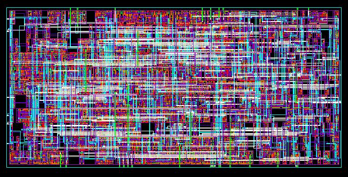
20 MacroModules (or 8192 bit) SRAM Generated by hard-macro module generator
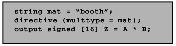
21 Soft MacroModules

22 Intellectual Property A Protocol Processor for Wireless
23 Semicustom Design Flow Design Capture Behavioral Design Iteration Pre-Layout Simulation Post-Layout Simulation HDL HDL Logic Logic Synthesis Floorplanning Placement Structural Physical Circuit Circuit Extraction Routing Tape-out


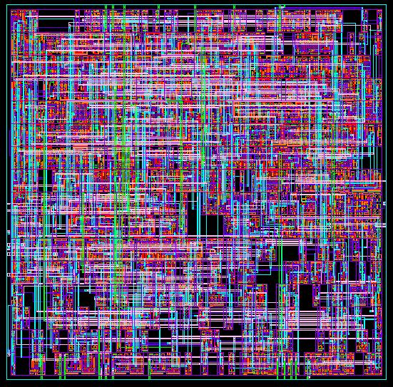
24 The Design Closure Problem Iterative Removal of Timing Violations (white lines)
25 Integrating Synthesis with Physical Design RTL (Timing) Constraints Physical Synthesis Macromodules Fixed netlists Netlist with Place-and-Route Info Place-and-Route Optimization Artwork
26 Late-Binding Implementation Array-based Pre-diffused (Gate Arrays) Pre-wired (FPGA's)
27 Gate Array Sea-of of-gates polysilicon V DD rows of uncommitted cells GND metal possible contact Uncommited Cell In1 In2 In3 In4 routing channel Committed Cell (4-input NOR Out
28 Sea-of of-gate Primitive Cells Oxide-isolation PMOS PMOS NMOS NMOS NMOS Using oxide-isolation Using gate-isolation
29 Example: Base Cell of Gate-Isolated GA continuous p-diff strip continuous n-diff strip contact for isolator VDD GND n-well p-well n-diff p-diff poly m1 m2 contact
30 Example: Flip-Flop Flop in Gate-Isolated GA VDD CLR Q CLK Q D GND
 Digital Integrated Circuits Courtesy LSI Logic")
31 Sea-of-gates Random Logic Memory Subsystem LSI Logic LEA300K (0.6 µm CMOS) Digital Integrated Circuits Courtesy LSI Logic
")

32 The return of gate arrays? Via programmable gate array (VPGA) Via-programmable cross-point metal-5 metal-6 programmable via Exploits regularity of interconnect [Pileggi02]
33 Prewired Arrays Classification of prewired arrays (or fieldprogrammable devices): Based on Programming Technique Fuse-based (program-once) Non-volatile EPROM based RAM based Programmable Logic Style Array-Based Look-up Table Programmable Interconnect Style Channel-routing Mesh networks
34 Fuse-Based FPGA antifuse polysilicon ONO dielectric n + antifuse diffusion 2 l Open by default, closed by applying current pulse
35 Array-Based Programmable Logic I 5 I 4 I 3 I 2 I 1 I 0 Programmable OR array I 3 I 2 I 1 I 0 Programmable OR array I 5 I 4 I 3 I 2 I 1 I 0 Fixed OR array Programmable AND array Fixed AND array Programmable AND array O 3 O 2 O 1 O 0 O 3 O 2 O 1 O 0 O 3 O 2 O 1 O 0 PLA PROM PAL Indicates programmable connection Indicates fixed connection
36 Programming a PROM 1 X 2 X 1 X 0 : programmed node NA NA f 1 f 0
37 More Complex PAL programmable AND array (2 i 3 jk) k macrocells 1 product terms j -wide OR array j D Q OUT j CLK macrocell A B C i i inputs i inputs, j minterms/macrocell, k macrocells
38 2-input mux as programmable logic block Configuration A B S F= A 0 B 1 S F X 1 X 0 Y 1 Y 0 Y X XY X 0 Y XY Y 0 X XY Y 1 X X 1 Y 1 0 X X 1 0 Y Y
39 Logic Cell of Actel Fuse-Based FPGA A B 1 SA C 1 Y D 1 SB S0 S1
40 Look-up Table Based Logic Cell Memory Out In Out ln1 ln2
41 LUT-Based Logic Cell C 1...C 4 4 Figure must be updated xx xxxx xxxx xxxx D 4 D 3 D 2 Logic function of xxx xx xx xx xx Bits control x xx x xxxx xx D 1 F 4 F 3 F 2 Logic function of xxx Logic function x of xxx x xx xx xx xx x Bits control xx x xx xx x xxxx x xx F 1 x xxxxx Xilinx 4000 Series H P x xx xx Multiplexer Controlled by Configuration Program x
42 Array-Based Programmable Wiring M Interconnect Point Programmed interconnection Input/output pin Cell Horizontal tracks Vertical tracks
43 Mesh-based Interconnect Network Switch Box Connect Box Interconnect Point
44 Transistor Implementation of Mesh
45 Hierarchical Mesh Network Use overlayed mesh to support longer connections Reduced fanout and reduced resistance
46 EPLD Block Diagram Primary inputs Macrocell

47 Altera MAX
48 Altera MAX Interconnect Architecture column channel row channel t PIA LAB1 LAB2 LAB PIA t PIA LAB6 Array-based (MAX ) Mesh-based (MAX 9000)
49 Field-Programmable Gate Arrays Fuse-based I/O Buffers Program/ Test/Diagnostics Vertical routes Standard-cell like floorplan I/O Buffers I/O Buffers Rows of logic modules Routing channels I/O Buffers
50 Xilinx 4000 Interconnect Architecture 12 Quad 8 Single 4 Double 3 Long CLB 2 Direct Connect Long Quad Long Global Clock Long Double Single Global Clock Carry Chain Direct Connect

51 RAM-based FPGA Xilinx XC4000ex

52 A Low-Energy FPGA (UC Berkeley) Array Size: 8x8 (2 x 4 LUT) Power Supply: 1.5V & 0.8V Configuration: Mapped as RAM Toggle Frequency: 125MHz Area: 3mm x 3mm

53 Larger Granularity FPGAs PADDI-2 (UC Berkeley) 1-mm 2-metal CMOS tech 1.2 x 1.2 mm 2 600k transistors 208-pin PGA fclock = 50 MHz P av = 3.6 5V Basic Module: Datapath
54 Design at a crossroad System-on on-a-chip Multi- Spectral Imager 500 k Gates FPGA RAM + 1 Gbit DRAM Preprocessing 64 SIMD Processor Array + SRAM Image Conditioning 100 GOPS Analog µc system +2 Gbit DRAM Recognition Embedded applications where cost, performance, and energy are the real issues! DSP and control intensive Mixed-mode Combines programmable and application-specific modules Software plays crucial role
55 Addressing the Design Complexity Issue Architecture Reuse Reuse comes in generations Generation Reuse element Status 1 st Standard cells We ll e s tablis he d 2 nd IP blo c ks Being introduced 3 rd Architecture Eme rging 4 th IC Early re s e arc h Source: Theo Claasen (Philips) DAC 00
56 Architecture ReUse Silicon System Platform Flexible architecture for hardware and software Specific (programmable) components Network architecture Software modules Rules and guidelines for design of HW and SW Has been successful in PC s Dominance of a few players who specify and control architecture Application-domain specific (difference in constraints) Speed (compute power) Dissipation Costs Real / non-real time data
57 Platform-Based Design Only the consumer gets freedom of choice; designers need freedom from choice (Orfali,, et al, 1996, p.522) A platform is a restriction on the space of possible implementation choices, providing a well-defined abstraction of the underlying technology for the application developer New platforms will be defined at the architecture-micro-architecture boundary They will be component-based, and will provide a range of choices from structured-custom to fully programmable implementations Key to such approaches is the representation of communication in the platform model Source:R.Newton

58 Berkeley Pleiades Processor Interface FPGA Reconfigurable Data-path ARM8 Core 0.25um 6-level metal CMOS 5.2mm x 6.7mm 1.2 Million transistors 40 MHz at 1V 2 extra supplies: 0.4V, 1.5V 1.5~2 mw power dissipation

59 Heterogeneous Programmable Platforms FPGA Fabric Embedded PowerPc Embedded memories Hardwired multipliers High-speed I/O Xilinx Vertex-II Pro
60 Summary Digital CMOS Design is kicking and healthy Some major challenges down the road caused by Deep Sub-micron Super GHz design Power consumption!!!! Reliability making it work Some new circuit solutions are bound to emerge Who can afford design in the years to come? Some major design methodology change in the making!
Design Methodologies. Digital Integrated Circuits A Design Perspective. Jan M. Rabaey Anantha Chandrakasan Borivoje Nikolic.
 Digital Integrated Circuits A Design Perspective Jan M. Rabaey Anantha Chandrakasan Borivoje Nikolic Design Methodologies December 10, 2002 L o g i c T r a n s i s t o r s p e r C h i p ( K ) 1 9 8 1 1
Lecture Perspectives. Administrivia
 Lecture 29-30 Perspectives Administrivia Final on Friday May 18 12:30-3:30 pm» Location: 251 Hearst Gym Topics all what was covered in class. Review Session Time and Location TBA Lab and hw scores to be
Lecture 30. Perspectives. Digital Integrated Circuits Perspectives
 Lecture 30 Perspectives Administrivia Final on Friday December 15 8 am Location: 251 Hearst Gym Topics all what was covered in class. Precise reading information will be posted on the web-site Review Session
Digital Integrated Circuits Perspectives. Administrivia
 Lecture 30 Perspectives Administrivia Final on Friday December 14, 2001 8 am Location: 180 Tan Hall Topics all what was covered in class. Review Session - TBA Lab and hw scores to be posted on the web
18nm FinFET. Lecture 30. Perspectives. Administrivia. Power Density. Power will be a problem. Transistor Count
 18nm FinFET Double-gate structure + raised source/drain Lecture 30 Perspectives Gate Silicon Fin Source BOX Gate X. Huang, et al, 1999 IEDM, p.67~70 Drain Si fin - Body! I d [ua/um] 400-1.50 V 350 300-1.25
EECS 427 Lecture 21: Design for Test (DFT) Reminders
 Reminders") EECS 427 Lecture 21: Design for Test (DFT) Readings: Insert H.3, CBF Ch 25 EECS 427 F09 Lecture 21 1 Reminders One more deadline Finish your project by Dec. 14 Schematic, layout, simulations, and final
EECS 427 Lecture 21: Design for Test (DFT) Readings: Insert H.3, CBF Ch 25 EECS 427 F09 Lecture 21 1 Reminders One more deadline Finish your project by Dec. 14 Schematic, layout, simulations, and final
Lecture 3, Handouts Page 1. Introduction. EECE 353: Digital Systems Design Lecture 3: Digital Design Flows, Simulation Techniques.
 Introduction EECE 353: Digital Systems Design Lecture 3: Digital Design Flows, Techniques Cristian Grecu grecuc@ece.ubc.ca Course web site: http://courses.ece.ubc.ca/353/ What have you learned so far?
PROGRAMMABLE ASICs. Antifuse SRAM EPROM
 PROGRAMMABLE ASICs FPGAs hold array of basic logic cells Basic cells configured using Programming Technologies Programming Technology determines basic cell and interconnect scheme Programming Technologies
2009 Spring CS211 Digital Systems & Lab 1 CHAPTER 3: TECHNOLOGY (PART 2)
") 1 CHAPTER 3: IMPLEMENTATION TECHNOLOGY (PART 2) Whatwillwelearninthischapter? we learn in this 2 How transistors operate and form simple switches CMOS logic gates IC technology FPGAs and other PLDs Basic
1 CHAPTER 3: IMPLEMENTATION TECHNOLOGY (PART 2) Whatwillwelearninthischapter? we learn in this 2 How transistors operate and form simple switches CMOS logic gates IC technology FPGAs and other PLDs Basic
Homework 10 posted just for practice. Office hours next week, schedule TBD. HKN review today. Your feedback is important!
 EE141 Fall 2005 Lecture 26 Memory (Cont.) Perspectives Administrative Stuff Homework 10 posted just for practice No need to turn in Office hours next week, schedule TBD. HKN review today. Your feedback
Disseny físic. Disseny en Standard Cells. Enric Pastor Rosa M. Badia Ramon Canal DM Tardor DM, Tardor
 Disseny físic Disseny en Standard Cells Enric Pastor Rosa M. Badia Ramon Canal DM Tardor 2005 DM, Tardor 2005 1 Design domains (Gajski) Structural Processor, memory ALU, registers Cell Device, gate Transistor
Technology Timeline. Transistors ICs (General) SRAMs & DRAMs Microprocessors SPLDs CPLDs ASICs. FPGAs. The Design Warrior s Guide to.
 SRAMs & DRAMs Microprocessors SPLDs CPLDs ASICs. FPGAs. The Design Warrior s Guide to.") FPGAs 1 CMPE 415 Technology Timeline 1945 1950 1955 1960 1965 1970 1975 1980 1985 1990 1995 2000 Transistors ICs (General) SRAMs & DRAMs Microprocessors SPLDs CPLDs ASICs FPGAs The Design Warrior s Guide
FPGAs 1 CMPE 415 Technology Timeline 1945 1950 1955 1960 1965 1970 1975 1980 1985 1990 1995 2000 Transistors ICs (General) SRAMs & DRAMs Microprocessors SPLDs CPLDs ASICs FPGAs The Design Warrior s Guide
FPGA Based System Design
 FPGA Based System Design Reference Wayne Wolf, FPGA-Based System Design Pearson Education, 2004 Why VLSI? Integration improves the design: higher speed; lower power; physically smaller. Integration reduces
Lecture 12 Memory Circuits. Memory Architecture: Decoders. Semiconductor Memory Classification. Array-Structured Memory Architecture RWM NVRWM ROM
 Semiconductor Memory Classification Lecture 12 Memory Circuits RWM NVRWM ROM Peter Cheung Department of Electrical & Electronic Engineering Imperial College London Reading: Weste Ch 8.3.1-8.3.2, Rabaey
Very Large Scale Integration (VLSI)
") Very Large Scale Integration (VLSI) Lecture 6 Dr. Ahmed H. Madian Ah_madian@hotmail.com Dr. Ahmed H. Madian-VLSI 1 Contents Array subsystems Gate arrays technology Sea-of-gates Standard cell Macrocell
Very Large Scale Integration (VLSI) Lecture 6 Dr. Ahmed H. Madian Ah_madian@hotmail.com Dr. Ahmed H. Madian-VLSI 1 Contents Array subsystems Gate arrays technology Sea-of-gates Standard cell Macrocell
PE713 FPGA Based System Design
 PE713 FPGA Based System Design Why VLSI? Dept. of EEE, Amrita School of Engineering Why ICs? Dept. of EEE, Amrita School of Engineering IC Classification ANALOG (OR LINEAR) ICs produce, amplify, or respond
ESE 570: Digital Integrated Circuits and VLSI Fundamentals
 ESE 570: Digital Integrated Circuits and VLSI Fundamentals Lec 23: April 12, 2016 VLSI Design and Variation Penn ESE 570 Spring 2016 Khanna Lecture Outline! Design Methodologies " Hierarchy, Modularity,
Introduction. Digital Integrated Circuits A Design Perspective. Jan M. Rabaey Anantha Chandrakasan Borivoje Nikolic. July 30, 2002
 Digital Integrated Circuits A Design Perspective Jan M. Rabaey Anantha Chandrakasan Borivoje Nikolic Introduction July 30, 2002 1 What is this book all about? Introduction to digital integrated circuits.
ECE260B CSE241A Winter Design Styles Multi-Vdd/ Vth Designs. Website: / vlsicad.ucsd.edu/ courses/ ece260bw05
 ECE260B CSE241A Winter 2005 Design Styles Multi-Vdd/ Vth Designs Website: / courses/ ece260bw05 ECE 260B CSE 241A Design Styles 1 The Design Problem Source: sematech97 A growing gap between design complexity
Reference. Wayne Wolf, FPGA-Based System Design Pearson Education, N Krishna Prakash,, Amrita School of Engineering
 FPGA Fabrics Reference Wayne Wolf, FPGA-Based System Design Pearson Education, 2004 CPLD / FPGA CPLD Interconnection of several PLD blocks with Programmable interconnect on a single chip Logic blocks executes
Design Methodologies. Design Trade-offs. System Design to Hardware. Design Gap. Speed (throughput and clock frequency) Area and
 Area and") Design Trade-offs Design Methodologies Viktor Öwall Dept. of Electrical and Infomation Technology Lund University Parts of this material was adapted from the instructor material to Jan M. Rabaey, Digital
Design Trade-offs Design Methodologies Viktor Öwall Dept. of Electrical and Infomation Technology Lund University Parts of this material was adapted from the instructor material to Jan M. Rabaey, Digital
Engr354: Digital Logic Circuits
 Engr354: Digital Logic Circuits Chapter 3: Implementation Technology Curtis Nelson Chapter 3 Overview In this chapter you will learn about: How transistors are used as switches; Integrated circuit technology;
DIGITAL INTEGRATED CIRCUITS A DESIGN PERSPECTIVE 2 N D E D I T I O N
 DIGITAL INTEGRATED CIRCUITS A DESIGN PERSPECTIVE 2 N D E D I T I O N Jan M. Rabaey, Anantha Chandrakasan, and Borivoje Nikolic CONTENTS PART I: THE FABRICS Chapter 1: Introduction (32 pages) 1.1 A Historical
PROGRAMMABLE ASIC INTERCONNECT
 PROGRAMMABLE ASIC INTERCONNECT The structure and complexity of the interconnect is largely determined by the programming technology and the architecture of the basic logic cell The first programmable ASICs
EC 1354-Principles of VLSI Design
 EC 1354-Principles of VLSI Design UNIT I MOS TRANSISTOR THEORY AND PROCESS TECHNOLOGY PART-A 1. What are the four generations of integrated circuits? 2. Give the advantages of IC. 3. Give the variety of
CMPEN 411 VLSI Digital Circuits Spring Lecture 24: Peripheral Memory Circuits
 CMPEN 411 VLSI Digital Circuits Spring 2011 Lecture 24: Peripheral Memory Circuits [Adapted from Rabaey s Digital Integrated Circuits, Second Edition, 2003 J. Rabaey, A. Chandrakasan, B. Nikolic] Sp11
ECE380 Digital Logic
 ECE380 Digital Logic Implementation Technology: Standard Chips and Programmable Logic Devices Dr. D. J. Jackson Lecture 10-1 Standard chips A number of chips, each with a few logic gates, are commonly
Lecture 9: Cell Design Issues
 Lecture 9: Cell Design Issues MAH, AEN EE271 Lecture 9 1 Overview Reading W&E 6.3 to 6.3.6 - FPGA, Gate Array, and Std Cell design W&E 5.3 - Cell design Introduction This lecture will look at some of the
Leakage Power Minimization in Deep-Submicron CMOS circuits
 Outline Leakage Power Minimization in Deep-Submicron circuits Politecnico di Torino Dip. di Automatica e Informatica 1019 Torino, Italy enrico.macii@polito.it Introduction. Design for low leakage: Basics.
Low-Power Digital CMOS Design: A Survey
 Low-Power Digital CMOS Design: A Survey Krister Landernäs June 4, 2005 Department of Computer Science and Electronics, Mälardalen University Abstract The aim of this document is to provide the reader with
L15: VLSI Integration and Performance Transformations
 L15: VLSI Integration and Performance Transformations Acknowledgement: Materials in this lecture are courtesy of the following sources and are used with permission. Curt Schurgers J. Rabaey, A. Chandrakasan,
EE 434 ASIC and Digital Systems. Prof. Dae Hyun Kim School of Electrical Engineering and Computer Science Washington State University.
 EE 434 ASIC and Digital Systems Prof. Dae Hyun Kim School of Electrical Engineering and Computer Science Washington State University Preliminaries VLSI Design System Specification Functional Design RTL
Introduction to CMOS VLSI Design (E158) Lecture 9: Cell Design
 Lecture 9: Cell Design") Harris Introduction to CMOS VLSI Design (E158) Lecture 9: Cell Design David Harris Harvey Mudd College David_Harris@hmc.edu Based on EE271 developed by Mark Horowitz, Stanford University MAH E158 Lecture
Harris Introduction to CMOS VLSI Design (E158) Lecture 9: Cell Design David Harris Harvey Mudd College David_Harris@hmc.edu Based on EE271 developed by Mark Horowitz, Stanford University MAH E158 Lecture
1. Introduction. Institute of Microelectronic Systems. Status of Microelectronics Technology. (nm) Core voltage (V) Gate oxide thickness t OX
 Core voltage (V) Gate oxide thickness t OX") Threshold voltage Vt (V) and power supply (V) 1. Introduction Status of s Technology 10 5 2 1 0.5 0.2 0.1 V dd V t t OX 50 20 10 5 2 Gate oxide thickness t OX (nm) Future VLSI chip 2005 2011 CMOS feature
Threshold voltage Vt (V) and power supply (V) 1. Introduction Status of s Technology 10 5 2 1 0.5 0.2 0.1 V dd V t t OX 50 20 10 5 2 Gate oxide thickness t OX (nm) Future VLSI chip 2005 2011 CMOS feature
Memory Basics. historically defined as memory array with individual bit access refers to memory with both Read and Write capabilities
 Memory Basics RAM: Random Access Memory historically defined as memory array with individual bit access refers to memory with both Read and Write capabilities ROM: Read Only Memory no capabilities for
EEC 118 Lecture #12: Dynamic Logic
 EEC 118 Lecture #12: Dynamic Logic Rajeevan Amirtharajah University of California, Davis Jeff Parkhurst Intel Corporation Outline Today: Alternative MOS Logic Styles Dynamic MOS Logic Circuits: Rabaey
Topics. Memory Reliability and Yield Control Logic. John A. Chandy Dept. of Electrical and Computer Engineering University of Connecticut
 Topics Memory Reliability and Yield Control Logic Reliability and Yield Noise Sources in T DRam BL substrate Adjacent BL C WBL α-particles WL leakage C S electrode C cross Transposed-Bitline Architecture
CS 6135 VLSI Physical Design Automation Fall 2003
 CS 6135 VLSI Physical Design Automation Fall 2003 1 Course Information Class time: R789 Location: EECS 224 Instructor: Ting-Chi Wang ( ) EECS 643, (03) 5742963 tcwang@cs.nthu.edu.tw Office hours: M56R5
Datorstödd Elektronikkonstruktion
 Datorstödd Elektronikkonstruktion [Computer Aided Design of Electronics] Zebo Peng, Petru Eles and Gert Jervan Embedded Systems Laboratory IDA, Linköping University http://www.ida.liu.se/~tdts80/~tdts80
EMT 251 Introduction to IC Design
 EMT 251 Introduction to IC Design (Pengantar Rekabentuk Litar Terkamir) Semester II 2011/2012 Introduction to IC design and Transistor Fundamental Some Keywords! Very-large-scale-integration (VLSI) is
PROGRAMMABLE ASIC INTERCONNECT
 ASICs...THE COURSE (1 WEEK) PROGRAMMABLE ASIC INTERCONNECT 7 Key concepts: programmable interconnect raw materials: aluminum-based metallization and a line capacitance of 0.2pFcm 1 7.1 Actel ACT Actel
Computer Aided Design of Electronics
 Computer Aided Design of Electronics [Datorstödd Elektronikkonstruktion] Zebo Peng, Petru Eles, and Nima Aghaee Embedded Systems Laboratory IDA, Linköping University www.ida.liu.se/~tdts01 Electronic Systems
+1 (479)
") Introduction to VLSI Design http://csce.uark.edu +1 (479) 575-6043 yrpeng@uark.edu Invention of the Transistor Vacuum tubes ruled in first half of 20th century Large, expensive, power-hungry, unreliable
Introduction to VLSI Design http://csce.uark.edu +1 (479) 575-6043 yrpeng@uark.edu Invention of the Transistor Vacuum tubes ruled in first half of 20th century Large, expensive, power-hungry, unreliable
Lecture 1. Tinoosh Mohsenin
 Lecture 1 Tinoosh Mohsenin Today Administrative items Syllabus and course overview Digital systems and optimization overview 2 Course Communication Email Urgent announcements Web page http://www.csee.umbc.edu/~tinoosh/cmpe650/
Lecture 4&5 CMOS Circuits
 Lecture 4&5 CMOS Circuits Xuan Silvia Zhang Washington University in St. Louis http://classes.engineering.wustl.edu/ese566/ Worst-Case V OL 2 3 Outline Combinational Logic (Delay Analysis) Sequential Circuits
Preface to Third Edition Deep Submicron Digital IC Design p. 1 Introduction p. 1 Brief History of IC Industry p. 3 Review of Digital Logic Gate
 Preface to Third Edition p. xiii Deep Submicron Digital IC Design p. 1 Introduction p. 1 Brief History of IC Industry p. 3 Review of Digital Logic Gate Design p. 6 Basic Logic Functions p. 6 Implementation
Digital Design and System Implementation. Overview of Physical Implementations
 Digital Design and System Implementation Overview of Physical Implementations CMOS devices CMOS transistor circuit functional behavior Basic logic gates Transmission gates Tri-state buffers Flip-flops
L15: VLSI Integration and Performance Transformations
 L15: VLSI Integration and Performance Transformations Average Cost of one transistor Acknowledgement: 10 1 0.1 0.01 0.001 0.0001 0.00001 $ 0.000001 Gordon Moore, Keynote Presentation at ISSCC 2003 0.0000001
FPGA Circuits. na A simple FPGA model. nfull-adder realization
 FPGA Circuits na A simple FPGA model nfull-adder realization ndemos Presentation References n Altera Training Course Designing With Quartus-II n Altera Training Course Migrating ASIC Designs to FPGA n
INSTITUTE OF AERONAUTICAL ENGINEERING (Autonomous) Dundigal, Hyderabad
 Dundigal, Hyderabad") INSTITUTE OF AERONAUTICAL ENGINEERING (Autonomous) Dundigal, Hyderabad - 500 0 ELECTRONICS AND COMMUNICATION ENGINEERING TUTORIAL QUESTION BANK Name : VLSI Design Code : A0 Regulation : R5 Structure :
INSTITUTE OF AERONAUTICAL ENGINEERING (Autonomous) Dundigal, Hyderabad - 500 0 ELECTRONICS AND COMMUNICATION ENGINEERING TUTORIAL QUESTION BANK Name : VLSI Design Code : A0 Regulation : R5 Structure :
Low Power VLSI Circuit Synthesis: Introduction and Course Outline
 Low Power VLSI Circuit Synthesis: Introduction and Course Outline Ajit Pal Professor Department of Computer Science and Engineering Indian Institute of Technology Kharagpur INDIA -721302 Agenda Why Low
Jan Rabaey, «Low Powere Design Essentials," Springer tml
 Jan Rabaey, «e Design Essentials," Springer 2009 http://web.me.com/janrabaey/lowpoweressentials/home.h tml Dimitrios Soudris, Christian Piguet, and Costas Goutis, Designing CMOS Circuits for Low POwer,
Jan M. Rabaey Anantha Chandrakasan Borivoje Nikolic. July 30, Digital EE141 Integrated Circuits 2nd Introduction
 Digital Integrated Circuits A Design Perspective Jan M. Rabaey Anantha Chandrakasan Borivoje Nikolic Introduction July 30, 2002 1 What is this book all about? Introduction to digital integrated circuits.
Policy-Based RTL Design
 Policy-Based RTL Design Bhanu Kapoor and Bernard Murphy bkapoor@atrenta.com Atrenta, Inc., 2001 Gateway Pl. 440W San Jose, CA 95110 Abstract achieving the desired goals. We present a new methodology to
Learning Outcomes. Spiral 2 8. Digital Design Overview LAYOUT
 2-8.1 2-8.2 Spiral 2 8 Cell Mark Redekopp earning Outcomes I understand how a digital circuit is composed of layers of materials forming transistors and wires I understand how each layer is expressed as
Memory, Latches, & Registers
 Memory, Latches, & Registers 1) Structured Logic Arrays 2) Memory Arrays 3) Transparent Latches 4) Saving a few bucks at toll booths 5) Edge-triggered Registers Friday s class will be a lecture rather
Novel Low-Overhead Operand Isolation Techniques for Low-Power Datapath Synthesis
 Novel Low-Overhead Operand Isolation Techniques for Low-Power Datapath Synthesis N. Banerjee, A. Raychowdhury, S. Bhunia, H. Mahmoodi, and K. Roy School of Electrical and Computer Engineering, Purdue University,
Jack Keil Wolf Lecture. ESE 570: Digital Integrated Circuits and VLSI Fundamentals. Lecture Outline. MOSFET N-Type, P-Type.
 ESE 570: Digital Integrated Circuits and VLSI Fundamentals Jack Keil Wolf Lecture Lec 3: January 24, 2019 MOS Fabrication pt. 2: Design Rules and Layout http://www.ese.upenn.edu/about-ese/events/wolf.php
CMOS VLSI IC Design. A decent understanding of all tasks required to design and fabricate a chip takes years of experience
 CMOS VLSI IC Design A decent understanding of all tasks required to design and fabricate a chip takes years of experience 1 Commonly used keywords INTEGRATED CIRCUIT (IC) many transistors on one chip VERY
WHAT ARE FIELD PROGRAMMABLE. Audible plays called at the line of scrimmage? Signaling for a squeeze bunt in the ninth inning?
 WHAT ARE FIELD PROGRAMMABLE Audible plays called at the line of scrimmage? Signaling for a squeeze bunt in the ninth inning? They re none of the above! We re going to take a look at: Field Programmable
Propagation Delay, Circuit Timing & Adder Design. ECE 152A Winter 2012
 Propagation Delay, Circuit Timing & Adder Design ECE 152A Winter 2012 Reading Assignment Brown and Vranesic 2 Introduction to Logic Circuits 2.9 Introduction to CAD Tools 2.9.1 Design Entry 2.9.2 Synthesis
Propagation Delay, Circuit Timing & Adder Design
 Propagation Delay, Circuit Timing & Adder Design ECE 152A Winter 2012 Reading Assignment Brown and Vranesic 2 Introduction to Logic Circuits 2.9 Introduction to CAD Tools 2.9.1 Design Entry 2.9.2 Synthesis
Programmable Interconnect. CPE/EE 428, CPE 528: Session #13. Actel Programmable Interconnect. Actel Programmable Interconnect
 Programmable Interconnect CPE/EE 428, CPE 528: Session #13 Department of Electrical and Computer Engineering University of Alabama in Huntsville In addition to programmable cells, programmable ASICs must
Introduction to Electronic Design Automation
 Introduction to Electronic Design Automation Jie-Hong Roland Jiang 江介宏 Department of Electrical Engineering National Taiwan University Spring 2014 1 Design Automation? 2 Course Info (1/4) Instructor Jie-Hong
CMOS Digital Logic Design with Verilog. Chapter1 Digital IC Design &Technology
 CMOS Digital Logic Design with Verilog Chapter1 Digital IC Design &Technology Chapter Overview: In this chapter we study the concept of digital hardware design & technology. This chapter deals the standard
VALLIAMMAI ENGINEERING COLLEGE SRM Nagar, Kattankulathur
 VALLIAMMAI ENGINEERING COLLEGE SRM Nagar, Kattankulathur 603 203. DEPARTMENT OF ELECTRONICS & COMMUNICATION ENGINEERING SUBJECT : EC6601 VLSI DESIGN QUESTION BANK SEM / YEAR: VI / IIIyear B.E. EC6601VLSI
A 0.9 V Low-power 16-bit DSP Based on a Top-down Design Methodology
 UDC 621.3.049.771.14:621.396.949 A 0.9 V Low-power 16-bit DSP Based on a Top-down Design Methodology VAtsushi Tsuchiya VTetsuyoshi Shiota VShoichiro Kawashima (Manuscript received December 8, 1999) A 0.9
ESE 570: Digital Integrated Circuits and VLSI Fundamentals
 ESE 570: Digital Integrated Circuits and VLSI Fundamentals Lec 3: January 24, 2019 MOS Fabrication pt. 2: Design Rules and Layout Penn ESE 570 Spring 2019 Khanna Jack Keil Wolf Lecture http://www.ese.upenn.edu/about-ese/events/wolf.php
VALLIAMMAI ENGINEERING COLLEGE
 VALLIAMMAI ENGINEERING COLLEGE SRM Nagar, Kattankulathur 603 203 DEPARTMENT OF ELECTRONICS AND COMMUNICATION ENGINEERING QUESTION BANK VI SEMESTER EC6601 VLSI Design Regulation 2013 Academic Year 2017
Chapter 3 Digital Logic Structures
 Chapter 3 Digital Logic Structures Transistor: Building Block of Computers Microprocessors contain millions of transistors Intel Pentium 4 (2): 48 million IBM PowerPC 75FX (22): 38 million IBM/Apple PowerPC
CHAPTER III THE FPGA IMPLEMENTATION OF PULSE WIDTH MODULATION
 34 CHAPTER III THE FPGA IMPLEMENTATION OF PULSE WIDTH MODULATION 3.1 Introduction A number of PWM schemes are used to obtain variable voltage and frequency supply. The Pulse width of PWM pulsevaries with
DESIGN & IMPLEMENTATION OF SELF TIME DUMMY REPLICA TECHNIQUE IN 128X128 LOW VOLTAGE SRAM
 DESIGN & IMPLEMENTATION OF SELF TIME DUMMY REPLICA TECHNIQUE IN 128X128 LOW VOLTAGE SRAM 1 Mitali Agarwal, 2 Taru Tevatia 1 Research Scholar, 2 Associate Professor 1 Department of Electronics & Communication
Advanced FPGA Design. Tinoosh Mohsenin CMPE 491/691 Spring 2012
 Advanced FPGA Design Tinoosh Mohsenin CMPE 491/691 Spring 2012 Today Administrative items Syllabus and course overview Digital signal processing overview 2 Course Communication Email Urgent announcements
EECS150 - Digital Design Lecture 15 - CMOS Implementation Technologies. Overview of Physical Implementations
 EECS150 - Digital Design Lecture 15 - CMOS Implementation Technologies Mar 12, 2013 John Wawrzynek Spring 2013 EECS150 - Lec15-CMOS Page 1 Overview of Physical Implementations Integrated Circuits (ICs)
EECS150 - Digital Design Lecture 9 - CMOS Implementation Technologies
 EECS150 - Digital Design Lecture 9 - CMOS Implementation Technologies Feb 14, 2012 John Wawrzynek Spring 2012 EECS150 - Lec09-CMOS Page 1 Overview of Physical Implementations Integrated Circuits (ICs)
! Review: MOS IV Curves and Switch Model. ! MOS Device Layout. ! Inverter Layout. ! Gate Layout and Stick Diagrams. ! Design Rules. !
 ESE 570: Digital Integrated Circuits and VLSI Fundamentals Lec 3: January 21, 2017 MOS Fabrication pt. 2: Design Rules and Layout Lecture Outline! Review: MOS IV Curves and Switch Model! MOS Device Layout!
Embedded System Hardware - Reconfigurable Hardware -
 2 Embedded System Hardware - Reconfigurable Hardware - Peter Marwedel Informatik 2 TU Dortmund Germany GOPs/J Courtesy: Philips Hugo De Man, IMEC, 27 Energy Efficiency of FPGAs 2, 28-2- Reconfigurable
Introduction to CMOS VLSI Design (E158) Lecture 5: Logic
 Lecture 5: Logic") Harris Introduction to CMOS VLSI Design (E158) Lecture 5: Logic David Harris Harvey Mudd College David_Harris@hmc.edu Based on EE271 developed by Mark Horowitz, Stanford University MAH E158 Lecture 5 1
Harris Introduction to CMOS VLSI Design (E158) Lecture 5: Logic David Harris Harvey Mudd College David_Harris@hmc.edu Based on EE271 developed by Mark Horowitz, Stanford University MAH E158 Lecture 5 1
Multi-Channel FIR Filters
 Chapter 7 Multi-Channel FIR Filters This chapter illustrates the use of the advanced Virtex -4 DSP features when implementing a widely used DSP function known as multi-channel FIR filtering. Multi-channel
EECS150 - Digital Design Lecture 19 CMOS Implementation Technologies. Recap and Outline
 EECS150 - Digital Design Lecture 19 CMOS Implementation Technologies Oct. 31, 2013 Prof. Ronald Fearing Electrical Engineering and Computer Sciences University of California, Berkeley (slides courtesy
ALPS: An Automatic Layouter for Pass-Transistor Cell Synthesis
 ALPS: An Automatic Layouter for Pass-Transistor Cell Synthesis Yasuhiko Sasaki Central Research Laboratory Hitachi, Ltd. Kokubunji, Tokyo, 185, Japan Kunihito Rikino Hitachi Device Engineering Kokubunji,
Sticks Diagram & Layout. Part II
 Sticks Diagram & Layout Part II Well and Substrate Taps Substrate must be tied to GND and n-well to V DD Metal to lightly-doped semiconductor forms poor connection called Shottky Diode Use heavily doped
EE141-Spring 2007 Digital Integrated Circuits
 EE141-Spring 2007 Digital Integrated Circuits Lecture 22 I/O, Power Distribution dders 1 nnouncements Homework 9 has been posted Due Tu. pr. 24, 5pm Project Phase 4 (Final) Report due Mo. pr. 30, noon
Lecture 0: Introduction
 Lecture 0: Introduction Introduction Integrated circuits: many transistors on one chip. Very Large Scale Integration (VLSI): bucketloads! Complementary Metal Oxide Semiconductor Fast, cheap, low power
Electronic Design Automation at Transistor Level by Ricardo Reis. Preamble
 1 Electronic Design Automation at Transistor Level by Ricardo Reis Preamble 1 Quintillion of Transistors 90 65 45 32 NM Electronic Design Automation at Transistor Level Ricardo Reis Universidade Federal
EE 330 Lecture 44. Digital Circuits. Dynamic Logic Circuits. Course Evaluation Reminder - All Electronic
 EE 330 Lecture 44 Digital Circuits Dynamic Logic Circuits Course Evaluation Reminder - All Electronic Digital Building Blocks Shift Registers Sequential Logic Shift Registers (stack) Array Logic Memory
PHYSICAL STRUCTURE OF CMOS INTEGRATED CIRCUITS. Dr. Mohammed M. Farag
 PHYSICAL STRUCTURE OF CMOS INTEGRATED CIRCUITS Dr. Mohammed M. Farag Outline Integrated Circuit Layers MOSFETs CMOS Layers Designing FET Arrays EE 432 VLSI Modeling and Design 2 Integrated Circuit Layers
Digital Systems Design
 Digital Systems Design Digital Systems Design and Test Dr. D. J. Jackson Lecture 1-1 Introduction Traditional digital design Manual process of designing and capturing circuits Schematic entry System-level
! Review: MOS IV Curves and Switch Model. ! MOS Device Layout. ! Inverter Layout. ! Gate Layout and Stick Diagrams. ! Design Rules. !
 ESE 570: Digital Integrated Circuits and VLSI Fundamentals Lec 3: January 21, 2016 MOS Fabrication pt. 2: Design Rules and Layout Lecture Outline! Review: MOS IV Curves and Switch Model! MOS Device Layout!
ESE 570: Digital Integrated Circuits and VLSI Fundamentals
 ESE 570: Digital Integrated Circuits and VLSI Fundamentals Lec 3: January 21, 2016 MOS Fabrication pt. 2: Design Rules and Layout Penn ESE 570 Spring 2016 Khanna Adapted from GATech ESE3060 Slides Lecture
2 MARK QUESTIONS & ANSWERS UNIT1-MOS TRANSISTOR PRINCIPLE
 2 MARK QUESTIONS & ANSWERS UNIT1-MOS TRANSISTOR PRINCIPLE 1.What are four generations of Integration Circuits? _ SSI (Small Scale Integration) _ MSI (Medium Scale Integration) _ LSI (Large Scale Integration)
CS302 - Digital Logic Design Glossary By
 CS302 - Digital Logic Design Glossary By ABEL : Advanced Boolean Expression Language; a software compiler language for SPLD programming; a type of hardware description language (HDL) Adder : A digital
EE 434 ASIC & Digital Systems
 EE 434 ASIC & Digital Systems Dae Hyun Kim EECS Washington State University Spring 2017 Course Website http://eecs.wsu.edu/~ee434 Themes Study how to design, analyze, and test a complex applicationspecific
CPE/EE 427, CPE 527 VLSI Design I: Homeworks 3 & 4
 CPE/EE 427, CPE 527 VLSI Design I: Homeworks 3 & 4 1 2 3 4 5 6 7 8 9 10 Sum 30 10 25 10 30 40 10 15 15 15 200 1. (30 points) Misc, Short questions (a) (2 points) Postponing the introduction of signals
Microelectronics, BSc course
 Microelectronics, BSc course MOS circuits: CMOS circuits, construction http://www.eet.bme.hu/~poppe/miel/en/14-cmos.pptx http://www.eet.bme.hu The abstraction level of our study: SYSTEM + MODULE GATE CIRCUIT
I/O Design EE141. Announcements. EE141-Fall 2006 Digital Integrated Circuits. Class Material. Pads + ESD Protection.
 EE141-Fall 2006 Digital Integrated Circuits nnouncements Homework 9 due on Thursday Lecture 26 I/O 1 2 Class Material Last lecture Timing Clock distribution Today s lecture I/O Power distribution Intro
Digital Systems Laboratory
 2012 Fall CSE140L Digital Systems Laboratory Lecture #2 by Dr. Choon Kim CSE Department, UCSD chk034@eng.ucsd.edu Lecture #2 1 Digital Technologies CPU(Central Processing Unit) GPU(Graphics Processing
LOW-POWER SOFTWARE-DEFINED RADIO DESIGN USING FPGAS
 LOW-POWER SOFTWARE-DEFINED RADIO DESIGN USING FPGAS Charlie Jenkins, (Altera Corporation San Jose, California, USA; chjenkin@altera.com) Paul Ekas, (Altera Corporation San Jose, California, USA; pekas@altera.com)
IES Digital Mock Test
 . The circuit given below work as IES Digital Mock Test - 4 Logic A B C x y z (a) Binary to Gray code converter (c) Binary to ECESS- converter (b) Gray code to Binary converter (d) ECESS- To Gray code
EE 330 Lecture 44. Digital Circuits. Ring Oscillators Sequential Logic Array Logic Memory Arrays. Final: Tuesday May 2 7:30-9:30
 EE 330 Lecture 44 igital Circuits Ring Oscillators Sequential Logic Array Logic Memory Arrays Final: Tuesday May 2 7:30-9:30 Review from Last Time ynamic Logic Basic ynamic Logic Gate V F A n PN Any of