Layout-based Modeling Methodology for Millimeter-Wave MOSFETs
|
|
|
- Ernest Lambert
- 5 years ago
- Views:
Transcription
1 Layout-based Modeling Methodology for Millimeter-Wave MOSFETs Yan Wang Institute of Microelectronics, Tsinghua University, Beijing, P. R. China, 184
2 Outline of Presentation Motivation Proposed Methodology Results and Discussions Summary 2
3 Outline of Presentation Motivation Proposed Methodology Results and Discussions Summary 3
4 Motivation High performance CMOS millimeterwave applications are emerging in endless stream 5G mobile Communication full-hd video streaming, and high speed wireless links at 6GHz 77-GHz Radar for automatic cruising Millimeter-wave imaging system for fine resolution using 94-GHz 4 band
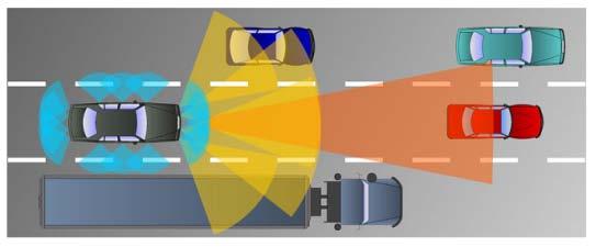
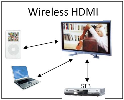

5 5G mobile Communication Radar for automatic cruising THz imaging system Sync & Go 5
6 Motivation A versatile model for mm-wave device is still not available in many situations, so accurate device models for efficient CAD simulation is needed. The RF model provided by PDK usually targets at low gigahertz applications and does not account for the complex high frequency effects and parasitic effects. CMOS circuits are fabricated on a resistive lossy substrate, and parameters associated with substrate parasitics must be added to 6 conventional models.
7 Motivation mm-wave transistors usually adopt a complex multi-finger layout. The challenge for modeling of mm-wave FETs mainly arises from that the model is limited to interpolated geometry range set by the largest and smallest measured devices due to unpredicted accuracy of extrapolation. It's extremely difficult to build a set of equations precisely covering all the parasitic capacitance, resistance of local metal wires, vias and contacts which connect a row of gate fingers, as well as from substrate loss over wide geometry range. 7

8 Motivation We made the assessment of NMOS multifinger transistors by TSMC 65nm, the mean-square error of Y-parameters between simulation and measurement results are shown. The error is a little bit striking. TSMC65nm RF NMOS.1~3.1GHz, the mean-square error of Y-parameters between simulation results and measurement. 8

9 Motivation Most of previous models focused on a fixed model, which is usually based on the BSIM enhanced by parasitic sub-circuit. Designers in many situations have to build a model of their own before diving into the design of integrated mm-wave circuit. Only those who specialize in modeling or who have very deep insight in device physics can handle such things Emami S., et al. Large-signal millimeter-wave CMOS modeling with BSIM3. RFIC-Symposium, 24:
10 Motivation In this work, a novel modeling methodology for millimeter-wave MOSFETs based on standard digital core model is proposed and investigated. This modeling methodology takes into account the layout effect and NQS effect. The proposed modeling methodology is compared with the measured data and good accuracy is achieved for a standard 9nm and 65nm CMOS technology. This proposed model has been successfully applied in 6GHz LNA design. 1
11 Outline of Presentation Motivation Proposed Methodology Results and Discussions Summary 11

12 Proposed Modeling Methodology Passive Device Thick Metal Layer NQS Effect 3D EM Simulation Digital Core Model Circuit Simulation Active Device Layout Parasitic Extraction Flow chart of the proposed modeling methodology 12
13 Proposed Modeling Methodology The standard core model aiming for digital circuit analysis is adopted directly. The core nonlinear elements such as gate drain capacitance, gatesource capacitance, output conductance, output transconductance, etc. can be described by BSIM. Extrinsic parasitic linear components introduced by device interconnections and related vias can be extracted by using Calibre xrc. NQS effect related nonlinear MOSFET characteristics are far more difficult to be determined for mm-wave multi-finger MOSFETs. 13
14 Proposed Modeling Methodology Gate Gate Source Drain Source Drain Gate Gate Gate Source Drain Source Drain Source Drain QS Approximate NQS It is first necessary to take into account the distributed nature of the device 14 structure along both its channel length and channel width.
15 Proposed Modeling Methodology For a one-fingered device, the intrinsic gate resistance Rg,i is given by Rg, sq W Rgi, = 3 L Where Rg,sq is the DC sheet resistance of the gate material, W is the width of the device, and L is the length of the channel region[1]. The factor 3 accounts for the distributed nature of the intrinsic gate region[2]. Rg,i increases in HF regime, in this work, it can be determined by Calibre extraction for simpliness. [1] Andrey V. Grebennikov, and Fujiang Lin, An efficient CAD-oriented large-signal MOSFET model, VOL. 48, NO. 1, P1732(2) [2] E. Abou-Allam and T. Manku, A small signal MOSFET model for radio frequency 15IC applications, IEEE Trans. Computer-Aided Design, pp , May 1997
16 Proposed Modeling Methodology Rgs accounts for the fact that channel charge cannot instantaneously respond to changes in the gate-source voltage. The signal applied to the gate suffers an additional equivalent gate resistance from the distributed channel resistance. Since the channel conductance seen by the source is related to g m, we would expect that the channel resistance (Rgs) is proportional to 1/g m. R gs 1 g m Rg consists of two parts: the Rg,i, contributed by the gate resistance and the Rg,nqs due 16 to channel charging resistance.
17 Proposed Modeling Methodology The transconductance delay τ is modeled by two ways: included by multiplying g m by exp(jωτ). The transconductance delay can also be represented by the transcapacitance C m. It has been known that BSIM model includes an NQS option and has been verified with measurements for devices. The NQS effect will equivalently introduce a transcapacitance between the drain and gate as the displacement current from Cgd can cancel partially the output current, which is equivalent to an 17 increased delay to the signal.
18 Proposed Modeling Methodology Gate R nqs Parasitic network between gate and source Core Model C nqs Parasitic network between gate and drain Source Parasitic network between drain and source Drain typical equivalent circuit model for mm-wave transistor proposed in this work, after the extraction, we achieve: 18 the Rnqs=1/5gm, Cnqs=1/1Cgg.
19 Outline of Presentation Motivation Proposed Methodology Results and Discussions Summary 19

20 Results and Discussion Y11 Y L=15nm W f =1u N f = Real, Measurement Imag, Measurement Real, Model Imag, Model Y12 Y22 x x Measured and modeled Y-parameters for MOSFETs 2 with L=15nm, Wf=1u and Nf=32 (TSMC 9nm).

21 Results and Discussion Y x Real, Measurement Imag, Measurement Real, Model Imag, Model L=1nm W f =1u N f =32 Y12-5 x x 1-3 Y Y Measured and modeled Y-parameters for MOSFETs with L=1nm, Wf=1u and Nf=32 (TSMC 9nm) 21
22 Results and Discussion Y11 15 x Real, Measurement Imag, Measurement Real, Model Imag, Model Y12 x L=6nm W f =1u N f =32-4 Y Y x Measured and modeled Y-parameters for MOSFETs with L=6nm, Wf=1u and Nf=32 (SMIC 65nm). 22
23 Results and Discussion Y11 Y L=6nm W f =1u N f = Real, Measurement Imag, Measurement Real, Model Imag, Model Y12 Y22 4 x x Measured and modeled Y-parameters for MOSFETs with L=6nm, Wf=1u and Nf=64 (SMIC 65nm). 23
24 Results and Discussion The proposed modeling methodology is also used to design a 6GHz low noise amplifier (LNA). VIN Vout stage1 Inp Inn Outp outn NVDD Inp stage2 Outp Inp Inn outn NVDD stage3 Inn Outp outn Inp VB Outn Neu_cap Outp VB Inn No balun here when used in the receiver three stage differential structure, transformer are used 24
25 Results and Discussion Spar/NF, [db] Spar/NF, [db] Blue: S21 Measurement PDK Model Proposed Model Green: NF Red: S22 Black: S Frequency, f [GHz] Blue: S21 PDK Model Proposed Model Green: NF Black: S11 Red: S22 The measurements is in a good agreement with the modeled results with a.5 GHz of frequency mismatch. The noise figure (NF) is also wellpredicted by the model Frequency, f [GHz] 25 Measured and modeled S-parameters and NF for LNA.
26 Results and Discussion Two-tone intermodulation distortion for LNA. Output tone power (db) 2-2 Main tone IM3 tone -4 Extend for IIP3 Line: Model input power (dbm) The measured and modeled IIP3 is -7dBm and -8dBm respectively. The input and output power is shown and the measured 1-dB compression point is -16dBm which matches the predicted value based on the proposed modeling 26 methodology. Again we got the satisfied results.
27 Outline of Presentation Motivation Proposed Methodology Results and Discussions Summary 27
28 Summary A novel modeling methodology for millimeter-wave MOSFETs based on standard digital core model is proposed and investigated. This methods takes into account the layout effect and NQS effect, which play a significant role in the millimeter-wave scope. The proposed method is compared with the measured data and good accuracy is achieved for a standard 9nm and 65nm CMOS technology. This proposed model has been successfully applied in 6G LNA design. When you have trouble in choosing HF transistor 28 model, you can try this method.
29 Thanks for attention! 29
1286 IEEE TRANSACTIONS ON ELECTRON DEVICES, VOL. 52, NO. 7, JULY MOSFET Modeling for RF IC Design
 1286 IEEE TRANSACTIONS ON ELECTRON DEVICES, VOL. 52, NO. 7, JULY 2005 MOSFET Modeling for RF IC Design Yuhua Cheng, Senior Member, IEEE, M. Jamal Deen, Fellow, IEEE, and Chih-Hung Chen, Member, IEEE Invited
Highly linear common-gate mixer employing intrinsic second and third order distortion cancellation
 Highly linear common-gate mixer employing intrinsic second and third order distortion cancellation Mahdi Parvizi a), and Abdolreza Nabavi b) Microelectronics Laboratory, Tarbiat Modares University, Tehran
A Volterra Series Approach for the Design of Low-Voltage CG-CS Active Baluns
 A Volterra Series Approach for the Design of Low-Voltage CG-CS Active Baluns Shan He and Carlos E. Saavedra Gigahertz Integrated Circuits Group Department of Electrical and Computer Engineering Queen s
Low-Power RF Integrated Circuit Design Techniques for Short-Range Wireless Connectivity
 Low-Power RF Integrated Circuit Design Techniques for Short-Range Wireless Connectivity Marvin Onabajo Assistant Professor Analog and Mixed-Signal Integrated Circuits (AMSIC) Research Laboratory Dept.
High Gain Low Noise Amplifier Design Using Active Feedback
 Chapter 6 High Gain Low Noise Amplifier Design Using Active Feedback In the previous two chapters, we have used passive feedback such as capacitor and inductor as feedback. This chapter deals with the
LINEARITY IMPROVEMENT OF CASCODE CMOS LNA USING A DIODE CONNECTED NMOS TRANSISTOR WITH A PARALLEL RC CIRCUIT
 Progress In Electromagnetics Research C, Vol. 17, 29 38, 2010 LINEARITY IMPROVEMENT OF CASCODE CMOS LNA USING A DIODE CONNECTED NMOS TRANSISTOR WITH A PARALLEL RC CIRCUIT C.-P. Chang, W.-C. Chien, C.-C.
An Asymmetrical Bulk CMOS Switch for 2.4 GHz Application
 Progress In Electromagnetics Research Letters, Vol. 66, 99 104, 2017 An Asymmetrical Bulk CMOS Switch for 2.4 GHz Application Lang Chen 1, * and Ye-Bing Gan 1, 2 Abstract A novel asymmetrical single-pole
ETI , Good luck! Written Exam Integrated Radio Electronics. Lund University Dept. of Electroscience
 und University Dept. of Electroscience EI170 Written Exam Integrated adio Electronics 2010-03-10, 08.00-13.00 he exam consists of 5 problems which can give a maximum of 6 points each. he total maximum
CHAPTER 3 CMOS LOW NOISE AMPLIFIERS
 46 CHAPTER 3 CMOS LOW NOISE AMPLIFIERS 3.1 INTRODUCTION The Low Noise Amplifier (LNA) plays an important role in the receiver design. LNA serves as the first block in the RF receiver. It is a critical
A New Model for Thermal Channel Noise of Deep-Submicron MOSFETS and its Application in RF-CMOS Design
 IEEE JOURNAL OF SOLID-STATE CIRCUITS, VOL. 36, NO. 5, MAY 2001 831 A New Model for Thermal Channel Noise of Deep-Submicron MOSFETS and its Application in RF-CMOS Design Gerhard Knoblinger, Member, IEEE,
A Low Power Single Ended Inductorless Wideband CMOS LNA with G m Enhancement and Noise Cancellation
 2017 International Conference on Electronic, Control, Automation and Mechanical Engineering (ECAME 2017) ISBN: 978-1-60595-523-0 A Low Power Single Ended Inductorless Wideband CMOS LNA with G m Enhancement
2.Circuits Design 2.1 Proposed balun LNA topology
 3rd International Conference on Multimedia Technology(ICMT 013) Design of 500MHz Wideband RF Front-end Zhengqing Liu, Zhiqun Li + Institute of RF- & OE-ICs, Southeast University, Nanjing, 10096; School
Low Noise Amplifier Design Methodology Summary By Ambarish Roy, Skyworks Solutions, Inc.
 February 2014 Low Noise Amplifier Design Methodology Summary By Ambarish Roy, Skyworks Solutions, Inc. Low Noise Amplifiers (LNAs) amplify weak signals received by the antenna in communication systems.
Designing a 960 MHz CMOS LNA and Mixer using ADS. EE 5390 RFIC Design Michelle Montoya Alfredo Perez. April 15, 2004
 Designing a 960 MHz CMOS LNA and Mixer using ADS EE 5390 RFIC Design Michelle Montoya Alfredo Perez April 15, 2004 The University of Texas at El Paso Dr Tim S. Yao ABSTRACT Two circuits satisfying the
CHAPTER 4 ULTRA WIDE BAND LOW NOISE AMPLIFIER DESIGN
 93 CHAPTER 4 ULTRA WIDE BAND LOW NOISE AMPLIFIER DESIGN 4.1 INTRODUCTION Ultra Wide Band (UWB) system is capable of transmitting data over a wide spectrum of frequency bands with low power and high data
A 3 5 GHz CMOS High Linearity Ultra Wideband Low Noise Amplifier in 0.18µ CMOS
 Proceedings of the 5th WSEAS Int. Conf. on CIRCUITS, SYSTEMS, ELECTRONICS, CONTROL & SIGNAL PROCESSING, Dallas, USA, November -, 6 5 A 5 GHz CMOS High Linearity Ultra Wideband Low Noise Amplifier in.8µ
DESIGN ANALYSIS AND COMPARATIVE STUDY OF RF RECEIVER FRONT-ENDS IN 0.18-µM CMOS
 International Journal of Electrical and Electronics Engineering Research Vol.1, Issue 1 (2011) 41-56 TJPRC Pvt. Ltd., DESIGN ANALYSIS AND COMPARATIVE STUDY OF RF RECEIVER FRONT-ENDS IN 0.18-µM CMOS M.
Measurement and Modeling of CMOS Devices in Short Millimeter Wave. Minoru Fujishima
 Measurement and Modeling of CMOS Devices in Short Millimeter Wave Minoru Fujishima Our position We are circuit designers. Our final target is not device modeling, but chip demonstration. Provided device
Aspemyr, Lars; Jacobsson, Harald; Bao, Mingquan; Sjöland, Henrik; Ferndal, Mattias; Carchon, G
 A 15 GHz and a 2 GHz low noise amplifier in 9 nm RF CMOS Aspemyr, Lars; Jacobsson, Harald; Bao, Mingquan; Sjöland, Henrik; Ferndal, Mattias; Carchon, G Published in: Topical Meeting on Silicon Monolithic
A 7-GHz 1.8-dB NF CMOS Low-Noise Amplifier
 852 IEEE JOURNAL OF SOLID-STATE CIRCUITS, VOL. 37, NO. 7, JULY 2002 A 7-GHz 1.8-dB NF CMOS Low-Noise Amplifier Ryuichi Fujimoto, Member, IEEE, Kenji Kojima, and Shoji Otaka Abstract A 7-GHz low-noise amplifier
Int. J. Electron. Commun. (AEU)
") Int. J. Electron. Commun. (AEÜ) 64 (2010) 978 -- 982 Contents lists available at ScienceDirect Int. J. Electron. Commun. (AEU) journal homepage: www.elsevier.de/aeue LETTER Linearization technique using
Int. J. Electron. Commun. (AEÜ) 64 (2010) 978 -- 982 Contents lists available at ScienceDirect Int. J. Electron. Commun. (AEU) journal homepage: www.elsevier.de/aeue LETTER Linearization technique using
A High Gain and Improved Linearity 5.7GHz CMOS LNA with Inductive Source Degeneration Topology
 A High Gain and Improved Linearity 5.7GHz CMOS LNA with Inductive Source Degeneration Topology Ch. Anandini 1, Ram Kumar 2, F. A. Talukdar 3 1,2,3 Department of Electronics & Communication Engineering,
WITH THE exploding growth of the wireless communication
 IEEE TRANSACTIONS ON MICROWAVE THEORY AND TECHNIQUES, VOL. 60, NO. 2, FEBRUARY 2012 387 0.6 3-GHz Wideband Receiver RF Front-End With a Feedforward Noise and Distortion Cancellation Resistive-Feedback
A 5 GHz CMOS Low Power Down-conversion Mixer for Wireless LAN Applications
 Proceedings of the 5th WSEAS Int. Conf. on CIRCUITS, SYSTES, ELECTRONICS, CONTROL & SIGNAL PROCESSING, Dallas, USA, November 1-, 2006 26 A 5 GHz COS Low Power Down-conversion ixer for Wireless LAN Applications
Chapter 2 CMOS at Millimeter Wave Frequencies
 Chapter 2 CMOS at Millimeter Wave Frequencies In the past, mm-wave integrated circuits were always designed in high-performance RF technologies due to the limited performance of the standard CMOS transistors
A 3 8 GHz Broadband Low Power Mixer
 PIERS ONLINE, VOL. 4, NO. 3, 8 361 A 3 8 GHz Broadband Low Power Mixer Chih-Hau Chen and Christina F. Jou Institute of Communication Engineering, National Chiao Tung University, Hsinchu, Taiwan Abstract
Systematic Transistor and Inductor Modeling for Millimeter-Wave Design ChuanKang Liang, Student Member, IEEE, and Behzad Razavi, Fellow, IEEE
 450 IEEE JOURNAL OF SOLID-STATE CIRCUITS, VOL. 44, NO. 2, FEBRUARY 2009 Systematic Transistor and Inductor Modeling for Millimeter-Wave Design ChuanKang Liang, Student Member, IEEE, and Behzad Razavi,
Evaluating and Optimizing Tradeoffs in CMOS RFIC Upconversion Mixer Design. by Dr. Stephen Long University of California, Santa Barbara
 Evaluating and Optimizing Tradeoffs in CMOS RFIC Upconversion Mixer Design by Dr. Stephen Long University of California, Santa Barbara It is not easy to design an RFIC mixer. Different, sometimes conflicting,
+ 2. Basic concepts of RFIC design
 + 2. Basic concepts of RFIC design 1 A. Thanachayanont RF Microelectronics + General considerations: 2 Units in RF design n Voltage gain and power gain n Ap and Av are equal if vin and vout appear across
57-65GHz CMOS Power Amplifier Using Transformer-Coupling and Artificial Dielectric for Compact Design
 57-65GHz CMOS Power Amplifier Using Transformer-Coupling and Artificial Dielectric for Compact Design Tim LaRocca, and Frank Chang PA Symposium 1/20/09 Overview Introduction Design Overview Differential
Design and optimization of a 2.4 GHz RF front-end with an on-chip balun
 Vol. 32, No. 9 Journal of Semiconductors September 2011 Design and optimization of a 2.4 GHz RF front-end with an on-chip balun Xu Hua( 徐化 ) 1;, Wang Lei( 王磊 ) 2, Shi Yin( 石寅 ) 1, and Dai Fa Foster( 代伐
POSTECH Activities on CMOS based Linear Power Amplifiers
 1 POSTECH Activities on CMOS based Linear Power Amplifiers Jan. 16. 2006 Bumman Kim, & Jongchan Kang MMIC Laboratory Department of EE, POSTECH Presentation Outline 2 Motivation Basic Design Approach CMOS
Post-Linearization of Differential CMOS Low Noise Amplifier Using Cross-Coupled FETs
 JOURNAL OF SEMICONDUCTOR TECHNOLOGY AND SCIENCE, VOL.8, NO.4, DECEMBER, 008 83 Post-Linearization of Differential CMOS Low Noise Amplifier Using Cross-Coupled FETs Tae-Sung Kim*, Seong-Kyun Kim*, Jin-Sung
A COMPACT WIDEBAND MATCHING 0.18-µM CMOS UWB LOW-NOISE AMPLIFIER USING ACTIVE FEED- BACK TECHNIQUE
 Progress In Electromagnetics Research C, Vol. 16, 161 169, 2010 A COMPACT WIDEBAND MATCHING 0.18-µM CMOS UWB LOW-NOISE AMPLIFIER USING ACTIVE FEED- BACK TECHNIQUE J.-Y. Li, W.-J. Lin, and M.-P. Houng Department
RF CMOS 0.5 µm Low Noise Amplifier and Mixer Design
 RF CMOS 0.5 µm Low Noise Amplifier and Mixer Design By VIKRAM JAYARAM, B.Tech Signal Processing and Communication Group & UMESH UTHAMAN, B.E Nanomil FINAL PROJECT Presented to Dr.Tim S Yao of Department
A low noise amplifier with improved linearity and high gain
 International Journal of Electronics and Computer Science Engineering 1188 Available Online at www.ijecse.org ISSN- 2277-1956 A low noise amplifier with improved linearity and high gain Ram Kumar, Jitendra
Dynamic behavior of the UTBB FDSOI MOSFET
 Dynamic behavior of the UTBB FDSOI MOSFET MOS-AK, March 12 th, 2015 Salim EL GHOULI 1, Patrick SCHEER 1, Thierry POIROUX 2, Jean-Michel SALLESE 3, Christophe LALLEMENT 4 André JUGE 1 1 STMicroelectronics,
DESIGN OF ZIGBEE RF FRONT END IC IN 2.4 GHz ISM BAND
 DESIGN OF ZIGBEE RF FRONT END IC IN 2.4 GHz ISM BAND SUCHITAV KHADANGA RFIC TECHNOLOGIES, BANGALORE, INDIA http://www.rficdesign.com Team-RV COLLEGE Ashray V K D V Raghu Sanjith P Hemagiri Rahul Verma
Performance Comparison of RF CMOS Low Noise Amplifiers in 0.18-µm technology scale
 Performance Comparison of RF CMOS Low Noise Amplifiers in 0.18-µm technology scale M.Sumathi* 1, S.Malarvizhi 2 *1 Research Scholar, Sathyabama University, Chennai -119,Tamilnadu sumagopi206@gmail.com
Design of A Wideband Active Differential Balun by HMIC
 Design of A Wideband Active Differential Balun by HMIC Chaoyi Li 1, a and Xiaofei Guo 2, b 1School of Electronics Engineering, Chongqing University of Posts and Telecommunications, Chongqing 400065, China;
A Compact GHz Ultra-Wideband Low-Noise Amplifier in 0.13-m CMOS Po-Yu Chang and Shawn S. H. Hsu, Member, IEEE
 IEEE TRANSACTIONS ON MICROWAVE THEORY AND TECHNIQUES, VOL. 58, NO. 10, OCTOBER 2010 2575 A Compact 0.1 14-GHz Ultra-Wideband Low-Noise Amplifier in 0.13-m CMOS Po-Yu Chang and Shawn S. H. Hsu, Member,
Low Noise Amplifier Design
 THE UNIVERSITY OF TEXAS AT DALLAS DEPARTMENT OF ELECTRICAL ENGINEERING EERF 6330 RF Integrated Circuit Design (Spring 2016) Final Project Report on Low Noise Amplifier Design Submitted To: Dr. Kenneth
Intermodulation Distortion Mitigation in Microwave Amplifiers and Frequency Converters
 Intermodulation Distortion Mitigation in Microwave Amplifiers and Frequency Converters Carlos Saavedra Professor of Electrical Engineering Queen s University Kingston, Ontario K7L 3N6 30 January 2017 Outline
Reduced Current Class AB Radio Receiver Stages Using Novel Superlinear Transistors with Parallel NMOS and PMOS Transistors at One GHz
 Copyright 2007 IEEE. Published in IEEE SoutheastCon 2007, March 22-25, 2007, Richmond, VA. Personal use of this material is permitted. However, permission to reprint/republish this material for advertising
1.Circuits Structure. 1.1 Capacitor cross-coupled
 3rd International Conference on Multimedia Technology(ICMT 013) Design of Low Voltage Low Noise Amplifier for 800MHz WSN Applications ZhaolongWu, ZhiqunLi + Institute of RF- & OE-ICs, Southeast University,
Wide-Band Two-Stage GaAs LNA for Radio Astronomy
 Progress In Electromagnetics Research C, Vol. 56, 119 124, 215 Wide-Band Two-Stage GaAs LNA for Radio Astronomy Jim Kulyk 1,GeWu 2, Leonid Belostotski 2, *, and James W. Haslett 2 Abstract This paper presents
Methodology for Simultaneous Noise and Impedance Matching in W-band LNAs
 Methodology for Simultaneous Noise and Impedance Matching in W-band LNAs Sean T. Nicolson and Sorin Voinigescu University of Toronto sorinv@eecg.toronto.edu CSICS-006, San Antonio, November 15, 006 1 Outline
Education on CMOS RF Circuit Reliability
 Education on CMOS RF Circuit Reliability Jiann S. Yuan 1 Abstract This paper presents a design methodology to study RF circuit performance degradations due to hot carrier and soft breakdown. The experimental
An up-conversion TV receiver front-end with noise canceling body-driven pmos common gate LNA and LC-loaded passive mixer
 LETTER IEICE Electronics Express, Vol.14, No.9, 1 11 An up-conversion TV receiver front-end with noise canceling body-driven pmos common gate LNA and LC-loaded passive mixer Donggu Im 1 and Ilku Nam 2a)
Direct calculation of metal oxide semiconductor field effect transistor high frequency noise parameters
 Direct calculation of metal oxide semiconductor field effect transistor high frequency noise parameters C. H. Chen and M. J. Deen a) Engineering Science, Simon Fraser University, Burnaby, British Columbia
RFIC DESIGN EXAMPLE: MIXER
 APPENDIX RFI DESIGN EXAMPLE: MIXER The design of radio frequency integrated circuits (RFIs) is relatively complicated, involving many steps as mentioned in hapter 15, from the design of constituent circuit
A COMPACT DOUBLE-BALANCED STAR MIXER WITH NOVEL DUAL 180 HYBRID. National Cheng-Kung University, No. 1 University Road, Tainan 70101, Taiwan
 Progress In Electromagnetics Research C, Vol. 24, 147 159, 2011 A COMPACT DOUBLE-BALANCED STAR MIXER WITH NOVEL DUAL 180 HYBRID Y.-A. Lai 1, C.-N. Chen 1, C.-C. Su 1, S.-H. Hung 1, C.-L. Wu 1, 2, and Y.-H.
DESIGN OF 3 TO 5 GHz CMOS LOW NOISE AMPLIFIER FOR ULTRA-WIDEBAND (UWB) SYSTEM
 SYSTEM") Progress In Electromagnetics Research C, Vol. 9, 25 34, 2009 DESIGN OF 3 TO 5 GHz CMOS LOW NOISE AMPLIFIER FOR ULTRA-WIDEBAND (UWB) SYSTEM S.-K. Wong and F. Kung Faculty of Engineering Multimedia University
Progress In Electromagnetics Research C, Vol. 9, 25 34, 2009 DESIGN OF 3 TO 5 GHz CMOS LOW NOISE AMPLIFIER FOR ULTRA-WIDEBAND (UWB) SYSTEM S.-K. Wong and F. Kung Faculty of Engineering Multimedia University
High-Linearity CMOS. RF Front-End Circuits
 High-Linearity CMOS RF Front-End Circuits Yongwang Ding Ramesh Harjani iigh-linearity CMOS tf Front-End Circuits - Springer Library of Congress Cataloging-in-Publication Data A C.I.P. Catalogue record
ISSCC 2006 / SESSION 11 / RF BUILDING BLOCKS AND PLLS / 11.9
 ISSCC 2006 / SESSION 11 / RF BUILDING BLOCKS AND PLLS / 11.9 11.9 A Single-Chip Linear CMOS Power Amplifier for 2.4 GHz WLAN Jongchan Kang 1, Ali Hajimiri 2, Bumman Kim 1 1 Pohang University of Science
Hot Topics and Cool Ideas in Scaled CMOS Analog Design
 Engineering Insights 2006 Hot Topics and Cool Ideas in Scaled CMOS Analog Design C. Patrick Yue ECE, UCSB October 27, 2006 Slide 1 Our Research Focus High-speed analog and RF circuits Device modeling,
A High-Level Model for Capacitive Coupled RC Oscillators
 A High-Level Model for Capacitive Coupled RC Oscillators João Casaleiro and Luís B. Oliveira Dep. Eng. Electrotécnica, Faculdade de Ciência e Tecnologia Universidade Nova de Lisboa, Caparica, Portugal
Radio-Frequency Circuits Integration Using CMOS SOI 0.25µm Technology
 Radio-Frequency Circuits Integration Using CMOS SOI.5µm Technology Frederic Hameau and Olivier Rozeau CEA/LETI - 7, rue des Martyrs -F-3854 GRENOBLE FRANCE cedex 9 frederic.hameau@cea.fr olivier.rozeau@cea.fr
A 2.4GHz Cascode CMOS Low Noise Amplifier
 A 2.4GHz Cascode CMOS Low Noise Amplifier Gustavo Campos Martins, Fernando Rangel de Sousa Federal University of Santa Catarina (UFSC) Integrated Circuits Laboratory (LCI) August 31, 2012 G. C. Martins,
Multi-Finger MOSFET Low Noise Amplifier Performance Analysis
 Wright State University CORE Scholar Browse all Theses and Dissertations Theses and Dissertations 2014 Multi-Finger MOSFET Low Noise Amplifier Performance Analysis Xiaomeng Zhang Wright State University
Characterization and Modeling of LDMOS Power FETs for RF Power Amplifier Applications
 Characterization and ing of LDMOS Power FETs for RF Power Amplifier Applications (Invited Paper) John Wood, Peter H. Aaen, and Jaime A. Plá Freescale Semiconductor Inc., RF Division 2100 E. Elliot Rd.,
On the design of low- voltage, low- power CMOS analog multipliers for RF applications
 C.J. Debono, F. Maloberti, J. Micallef: "On the design of low-voltage, low-power CMOS analog multipliers for RF applications"; IEEE Transactions on Very Large Scale Integration (VLSI) Systems, Vol. 10,
CMOS RFIC Design for Direct Conversion Receivers. Zhaofeng ZHANG Supervisor: Dr. Jack Lau
 CMOS RFIC Design for Direct Conversion Receivers Zhaofeng ZHANG Supervisor: Dr. Jack Lau Outline of Presentation Background Introduction Thesis Contributions Design Issues and Solutions A Direct Conversion
4-Bit Ka Band SiGe BiCMOS Digital Step Attenuator
 Progress In Electromagnetics Research C, Vol. 74, 31 40, 2017 4-Bit Ka Band SiGe BiCMOS Digital Step Attenuator Muhammad Masood Sarfraz 1, 2, Yu Liu 1, 2, *, Farman Ullah 1, 2, Minghua Wang 1, 2, Zhiqiang
Design of a Low Noise Amplifier using 0.18µm CMOS technology
 The International Journal Of Engineering And Science (IJES) Volume 4 Issue 6 Pages PP.11-16 June - 2015 ISSN (e): 2319 1813 ISSN (p): 2319 1805 Design of a Low Noise Amplifier using 0.18µm CMOS technology
A 600 GHz Varactor Doubler using CMOS 65nm process
 A 600 GHz Varactor Doubler using CMOS 65nm process S.H. Choi a and M.Kim School of Electrical Engineering, Korea University E-mail : hyperleonheart@hanmail.net Abstract - Varactor and active mode doublers
Small Signal Modelling of InGaAs/InAlAs phemt for low noise applications
 Small Signal Modelling of InGaAs/InAlAs phemt for low noise applications N. Ahmad and M. Mohamad Isa School of Microelectronic Engineering, Universiti Malaysia Perlis, Pauh Putra Campus, 26 Arau, Perlis,
A Wideband Single-balanced Down-mixer for the 60 GHz Band in 65 nm CMOS
 A Wideband Single-balanced Down-mixer for the GHz Band in 5 nm CMOS Michael Kraemer, Mariano Ercoli, Daniela Dragomirescu, Robert Plana To cite this version: Michael Kraemer, Mariano Ercoli, Daniela Dragomirescu,
A 9 21 GHz MINIATURE MONOLITHIC IMAGE REJECT MIXER IN 0.18-µM CMOS TECHNOLOGY
 Progress In Electromagnetics Research Letters, Vol. 17, 105 114, 2010 A 9 21 GHz MINIATURE MONOLITHIC IMAGE REJECT MIXER IN 0.18-µM CMOS TECHNOLOGY W.-C. Chien, C.-M. Lin, Y.-H. Chang, and Y.-H. Wang Department
Design and Implementation of a 1-5 GHz UWB Low Noise Amplifier in 0.18 um CMOS
 Downloaded from vbn.aau.dk on: marts 20, 2019 Aalborg Universitet Design and Implementation of a 1-5 GHz UWB Low Noise Amplifier in 0.18 um CMOS Shen, Ming; Tong, Tian; Mikkelsen, Jan H.; Jensen, Ole Kiel;
2.2 INTERCONNECTS AND TRANSMISSION LINE MODELS
 CHAPTER 2 MODELING OF SELF-HEATING IN IC INTERCONNECTS AND INVESTIGATION ON THE IMPACT ON INTERMODULATION DISTORTION 2.1 CONCEPT OF SELF-HEATING As the frequency of operation increases, especially in the
Extraction of Transmission Line Parameters and Effect of Conductive Substrates on their Characteristics
 ROMANIAN JOURNAL OF INFORMATION SCIENCE AND TECHNOLOGY Volume 19, Number 3, 2016, 199 212 Extraction of Transmission Line Parameters and Effect of Conductive Substrates on their Characteristics Saurabh
Design of Gate-All-Around Tunnel FET for RF Performance
 Drain Current (µa/µm) International Journal of Computer Applications (97 8887) International Conference on Innovations In Intelligent Instrumentation, Optimization And Signal Processing ICIIIOSP-213 Design
Voltage-variable attenuator MMIC using phase cancellation
 Voltage-variable attenuator MMIC using phase cancellation C.E. Saavedra and B.R. Jackson Abstract: A new microwave voltage-variable attenuator integrated circuit operating from 1. GHz to 3.5 GHz with a
1-13GHz Wideband LNA utilizing a Transformer as a Compact Inter-stage Network in 65nm CMOS
 -3GHz Wideband LNA utilizing a Transformer as a Compact Inter-stage Network in 65nm CMOS Hyohyun Nam and Jung-Dong Park a Division of Electronics and Electrical Engineering, Dongguk University, Seoul E-mail
Design technique of broadband CMOS LNA for DC 11 GHz SDR
 Design technique of broadband CMOS LNA for DC 11 GHz SDR Anh Tuan Phan a) and Ronan Farrell Institute of Microelectronics and Wireless Systems, National University of Ireland Maynooth, Maynooth,Co. Kildare,
Design of a 0.7~3.8GHz Wideband. Power Amplifier in 0.18-µm CMOS Process. Zhiyuan Li, Xiangning Fan
 Applied Mechanics and Materials Online: 2013-08-16 ISSN: 1662-7482, Vol. 364, pp 429-433 doi:10.4028/www.scientific.net/amm.364.429 2013 Trans Tech Publications, Switzerland Design of a 0.7~3.8GHz Wideband
Tradeoffs and Optimization in Analog CMOS Design
 Tradeoffs and Optimization in Analog CMOS Design David M. Binkley University of North Carolina at Charlotte, USA A John Wiley & Sons, Ltd., Publication Contents Foreword Preface Acknowledgmerits List of
A 15.5 db, Wide Signal Swing, Dynamic Amplifier Using a Common- Mode Voltage Detection Technique
 A 15.5 db, Wide Signal Swing, Dynamic Amplifier Using a Common- Mode Voltage Detection Technique James Lin, Masaya Miyahara and Akira Matsuzawa Tokyo Institute of Technology, Japan Matsuzawa & Okada Laḃ
Document Version Publisher s PDF, also known as Version of Record (includes final page, issue and volume numbers)
") A 2V Iductorless Receiver Front-End for Multi-Standard Wireless Applications Vidojkovic, V; Sanduleanu, MAT; van der Tang, JD; Baltus, PGM; van Roermund, AHM Published in: IEEE Radio and Wireless Symposium,
A 2V Iductorless Receiver Front-End for Multi-Standard Wireless Applications Vidojkovic, V; Sanduleanu, MAT; van der Tang, JD; Baltus, PGM; van Roermund, AHM Published in: IEEE Radio and Wireless Symposium,
A 3.5 GHz Low Noise, High Gain Narrow Band Differential Low Noise Amplifier Design for Wi-MAX Applications
 International Journal of Electronics Engineering Research. ISSN 0975-6450 Volume 9, Number 4 (2017) pp. 505-516 Research India Publications http://www.ripublication.com A 3.5 GHz Low Noise, High Gain Narrow
Design and Simulation Study of Active Balun Circuits for WiMAX Applications
 Design and Simulation Study of Circuits for WiMAX Applications Frederick Ray I. Gomez 1,2,*, John Richard E. Hizon 2 and Maria Theresa G. De Leon 2 1 New Product Introduction Department, Back-End Manufacturing
Contents. Contents... v. Preface... xiii. Chapter 1 Introduction...1. Chapter 2 Significant Physical Effects In Modern MOSFETs...
 Contents Contents... v Preface... xiii Chapter 1 Introduction...1 1.1 Compact MOSFET Modeling for Circuit Simulation...1 1.2 The Trends of Compact MOSFET Modeling...5 1.2.1 Modeling new physical effects...5
Design of a CMOS Distributed Power Amplifier with Gradual Changed Gain Cells
 Chinese Journal of Electronics Vol.27, No.6, Nov. 2018 Design of a CMOS Distributed Power Amplifier with Gradual Changed Gain Cells ZHANG Ying 1,2,LIZeyou 1,2, YANG Hua 1,2,GENGXiao 1,2 and ZHANG Yi 1,2
A 3-Stage Shunt-Feedback Op-Amp having 19.2dB Gain, 54.1dBm OIP3 (2GHz), and 252 OIP3/P DC Ratio
, and 252 OIP3/P DC Ratio") International Microwave Symposium 2011 Chart 1 A 3-Stage Shunt-Feedback Op-Amp having 19.2dB Gain, 54.1dBm OIP3 (2GHz), and 252 OIP3/P DC Ratio Zach Griffith, M. Urteaga, R. Pierson, P. Rowell, M. Rodwell,
International Microwave Symposium 2011 Chart 1 A 3-Stage Shunt-Feedback Op-Amp having 19.2dB Gain, 54.1dBm OIP3 (2GHz), and 252 OIP3/P DC Ratio Zach Griffith, M. Urteaga, R. Pierson, P. Rowell, M. Rodwell,
REFERENCES. [1] P. J. van Wijnen, H. R. Claessen, and E. A. Wolsheimer, A new straightforward
![REFERENCES. [1] P. J. van Wijnen, H. R. Claessen, and E. A. Wolsheimer, A new straightforward](/thumbs/94/121712130.jpg "REFERENCES. [1] P. J. van Wijnen, H. R. Claessen, and E. A. Wolsheimer, A new straightforward") REFERENCES [1] P. J. van Wijnen, H. R. Claessen, and E. A. Wolsheimer, A new straightforward calibration and correction procedure for on-wafer high-frequency S-parameter measurements (45 MHz 18 GHz), in
REFERENCES [1] P. J. van Wijnen, H. R. Claessen, and E. A. Wolsheimer, A new straightforward calibration and correction procedure for on-wafer high-frequency S-parameter measurements (45 MHz 18 GHz), in
Including the proper parasitics in a nonlinear
 Effects of Parasitics in Circuit Simulations Simulation accuracy can be improved by including parasitic inductances and capacitances By Robin Croston California Eastern Laboratories Including the proper
Pulse IV and pulsed S-parameter Parametric Analysis with AMCAD PIV & AGILENT PNA-X
 Pulse IV and pulsed S-parameter Parametric Analysis with AMCAD PIV & AGILENT PNA-X Tony Gasseling gasseling@amcad-engineering.com 1 Components PA Design Flow Measurement system Measurement Data base Circuits
HIGH-GAIN CMOS LOW NOISE AMPLIFIER FOR ULTRA WIDE-BAND WIRELESS RECEIVER
 Progress In Electromagnetics Research C, Vol. 7, 183 191, 2009 HIGH-GAIN CMOS LOW NOISE AMPLIFIER FOR ULTRA WIDE-BAND WIRELESS RECEIVER A. Dorafshan and M. Soleimani Electrical Engineering Department Iran
2005 IEEE. Reprinted with permission.
 P. Sivonen, A. Vilander, and A. Pärssinen, Cancellation of second-order intermodulation distortion and enhancement of IIP2 in common-source and commonemitter RF transconductors, IEEE Transactions on Circuits
30% PAE W-band InP Power Amplifiers using Sub-quarter-wavelength Baluns for Series-connected Power-combining
 2013 IEEE Compound Semiconductor IC Symposium, October 13-15, Monterey, C 30% PAE W-band InP Power Amplifiers using Sub-quarter-wavelength Baluns for Series-connected Power-combining 1 H.C. Park, 1 S.
Indium Phosphide and Related Materials Selectively implanted subcollector DHBTs
 Indium Phosphide and Related Materials - 2006 Selectively implanted subcollector DHBTs Navin Parthasarathy, Z. Griffith, C. Kadow, U. Singisetti, and M.J.W. Rodwell Dept. of Electrical and Computer Engineering,
IC design for wireless system
 IC design for wireless system Lecture 6 Dr. Ahmed H. Madian Ahmed.madian@guc.edu.eg 1 outlines Introduction to mixers Mixer metrics Mixer topologies Mixer performance analysis Mixer design issues Dr. Ahmed
WITH continuous downscaling of the CMOS technology,
 IEEE TRANSACTIONS ON ELECTRON DEVICES, VOL. 52, NO. 5, MAY 2005 973 Look-Up Table Approach for RF Circuit Simulation Using a Novel Measurement Technique Saurabh N. Agarwal, Anuranjan Jha, Student Member,
ISSCC 2003 / SESSION 20 / WIRELESS LOCAL AREA NETWORKING / PAPER 20.5
 ISSCC 2003 / SESSION 20 / WIRELESS LOCAL AREA NETWORKING / PAPER 20.5 20.5 A 2.4GHz CMOS Transceiver and Baseband Processor Chipset for 802.11b Wireless LAN Application George Chien, Weishi Feng, Yungping
E3 237 Integrated Circuits for Wireless Communication
 E3 237 Integrated Circuits for Wireless Communication Lecture 8: Noise in Components Gaurab Banerjee Department of Electrical Communication Engineering, Indian Institute of Science, Bangalore banerjee@ece.iisc.ernet.in
Design and power optimization of CMOS RF blocks operating in the moderate inversion region
 Design and power optimization of CMOS RF blocks operating in the moderate inversion region Leonardo Barboni, Rafaella Fiorelli, Fernando Silveira Instituto de Ingeniería Eléctrica Facultad de Ingeniería
A Miniaturized 70-GHz Broadband Amplifier in 0.13-m CMOS Technology Jun-De Jin and Shawn S. H. Hsu, Member, IEEE
 3086 IEEE TRANSACTIONS ON MICROWAVE THEORY AND TECHNIQUES, VOL. 56, NO. 12, DECEMBER 2008 A Miniaturized 70-GHz Broadband Amplifier in 0.13-m CMOS Technology Jun-De Jin and Shawn S. H. Hsu, Member, IEEE
A new nonlinear HEMT model allowing accurate simulation of very low IM 3 levels for high-frequency highly linear amplifiers design
 A new nonlinear HEMT model allowing accurate simulation of very low IM 3 levels for high-frequency highly linear amplifiers design J. Lhortolary 1, C. Chang 1, T. Reveyrand 2, M. Camiade 1, M. Campovecchio
Linearity Enhancement of Folded Cascode LNA for Narrow Band Receiver
 Linearity Enhancement of Folded Cascode LNA for Narrow Band Receiver K.Parimala 1, K.Raju 2 P.G. Student, Department of ECE, GPREC (Autonomous), Kurnool, A.P, India 1 Assistant Professor, Department of