The U2-HULLZ Universal Utility Hulls
|
|
|
- Cecilia Diane Small
- 5 years ago
- Views:
Transcription

1 A simple, practical, 2 module wedge hull design, that can be scaled to satisfy almost any small boating requirement, and easily modified to suite a builders unique needs. Universal Utility Hulls Drawn Ken Simpson Designs Rev. Jul Print in Landscape Mode with ¼ inch borders. 8' 42 ' 22 Single Occupant 28 6 step thru STANDARD HULL 8'L x 3'W x 12 H Dual Occupant Plus step thru 250 pound capacity 36 MEDIUM HULL 10'L x 3-3/4'W x 16 H pound capacity 50 ' TOP VIEW LONG HULL 9'L x 3-1/2'W x 15 H NESTED SIDE VIEW step thru 360 pound capacity Dual Occupant For all versions, the froward module can nest in the rear module for transport and storage. The optional pointed bow shape on the larger hulls should have minimal buoyancy effect, but will improve rough water capability. However, it is more difficult to construct. 30 NARROW HULL 8'L x 2-1/2W' x 10 H Paddle Only 225 pound capacity BIG HULL 12L' x 4'W x 18 H Triple Occupant 30 Single Occupant 24 6 step thru 45 Also refer to the 1 SHEET WEDGE free plans step thru pound capacity TYPICAL OPTIONS for larger models Recessed Motor Mount Page 1 of 30 This is an experimental design drawn up by an untrained amateur. The Designer accepts no liability for any loss, harm or damage sustained during construction or use. Builders may use these plans to construct a small quantity of boats for their own use only. Commercial manufacturers must ask the Designer for permission.
2 General Notes The idea for the U2-Hullz design is intended to provide a simple yet multi-useful, truly portable hull configuration. It includes an ample beam, great freeboard, generous volume, seating variety, and safety buoyancy. It is sturdy, easy to build, very portable and utilizes a standard trolling or small gas motor for power. To have strength and yet be lightweight, the plans use some non-traditional methods of assembly, specifically the Tape & Glue 2 construction process developed and incorporated by the designer. This provides a durable, yet truly portable, finished boat, and the building process is easily mastered by the home handyman and amateur boat builder. As a result, only hand tools, a jig-saw, a power drill and a large carpenters square, scissors, and tape measure are all that will be required throughout the assembly process. Be selective in your choice of materials. Use plywood that is preferably exterior rated. Marine Plywood is very expensive, so the use of ACX Grade is recommended, but be choosy. It is important to note, the final choice of materials is the decision of the builder. We have made specific recommendations, but if the builder has previous experience with different methods and materials, that is their choice, and we respect that decision. Certainly, minor changes in design are encouraged, to provide a 'custom' boat to satisfy a builders specific needs. We do not make changes to the drawings. This would be up to the individual builder, and their responsibility. Also, it is very important that none of the basic design parameters be drastically modified, as this may adversely affect overall boat safety or performance. Seating choice is also up to the builder. Bench type seating is suggested, but pedestal seats can be implemented. It should also be noted that the hull modules can be glued and screwed together, for those that do not have limitations of storage or transportation. The hull will be constructed using 1/4 plywood, for greater durability, or the exterior could also be fiberglassed, allowing yet thinner and lighter plywood hull building material. Any questions or comments regarding the construction and/or design of this project will be responded to in a timely fashion. Note: These plans are hand drawn one line at a time, not CAD, and as such are prone to minor drawing flaws. Thank you for your interest, and for purchasing these plans, and good luck with your project. And don t forget to visit for new designs and updates. Happy Boating! Ken Simpson, Designer Page 2
3 Universal Utility Modeled after my popular wedge design boats, it was only natural that I create a hull shape with features that will satisfy many different boating applications, by just adjusting the physical size of the hull. The 2 module design allows for transport in a vehicle, without the need of a trailer. Typical uses are as a small weekend fishing boat for one, a larger 2 occupant cruiser, the big hull for 3 adults, and a couple of children, or a narrow hull for effortless paddling for one adult. Optional Bow on larger hulls 4 Degree Sides Optional 10 inch access ports MEDIUM HULL 29 Bow Note: The Forward and Rear Bulkheads can be modified by the builder to For another hull size, merely replace the dimensions shown in RED, with those on Page 1 of the Hull you want to build. 36 Center Bulkhead Note: The rear bulkhead and transom could be modified to mount an optional enclosed motor. Transom 8 satisfy specific storage, seating or power needs. 1 x 2 Rub Rails Safety Buoyancy & Dry Storage 45 1 x 2 Skids 50 All straight line cuts, for easy assembly. 10 feet Forward Bulkhead Rear Bulkhead 16 Safety Buoyancy 3 Fixed Size Variations Skids *Standard: 8'L x 3'W x 12 H *Narrow: 8'L x 2-1/2' W x 10 H *Long: 9'L x 3-1/2'W x 15 H *Medium: 10'L x 3-3/4'W x 16 H (shown) *Big: 12'L x 4'W x 18 H Other sizes must maintain the 4 Degree side angle for proper nesting purposes. Besides the obvious, many other options are available to make the boat a custom fit to your needs. For example, the height of the side panels can be adjusted to conform to your vehicles storage opening. And, you can build into the forward module holding boxes for bait, or camping equipment. Also, the transom can be modified to accept a motor of choice, electric or a small.gas outboard. Seating variations are defined on the plans, and even a sleep onboard option is available. So don't hesitate, start construction of your U2 dream boat today! Page 3
4 PRE-CONSTRUCTION NOTES The previous three pages should have given you a good idea of the U2 Hullz concept, and what the different size options can provide. It is important to note that construction methods, and hull features, will change due to load and performance factors. For example, the smaller hulls will utilize ¼ inch plywood for all hull panels (sides, decks and bottom), while the larger hulls will need ½ inch, or thicker, for the base and bulkhead panels. In some instances the builder will be responsible for making this decision, based primarily on their intended use and capacity factors. So, the construction notes that follow are intended as recommended processes, which can, and should, be modified to suite the builders needs and prior boat building experience. The Medium Hull design is being detailed, as it embodies the primary features of both the smaller and larger size hulls. Remember, read and understand the building instructions thoroughly prior to starting construction. Finally, there are 2 construction Laws to also remember when building a wooden boat.. While planning, marking and cutting the plywood: Measure twice, and cut once! and When actual construction begins: Murphy's Law: The Glue Dries Before The Mistake Is Found! These Laws pretty much dictate that attention to detail is a must. Don't forget, people will rely on you for their safety! IMPORTANT Remember, when laying out the panels on the plywood, pencil mark on the C side only. The good side A must be facing down. This is because you will want to cut the panels from the C side, to prevent splintering on the good side of the plywood, which always faces to the outside of the hull. And also remember, there is a port (left) side panel and a starboard (right) side panel. The plywood sheets are laid out to provide this orientation. Also Note: All other panels will be Cut to Fit. This means that they will be measured, or traced, from the sub-assembly to which they must be assembled, and then cut to the exact size. Base and Deck panels are a good example of this. NOW, here is where the fun begins. The methods and materials used for the first assembly will be the same for all future assemblies. Besides the Plywood, the next most commonly used material will be 1 x 2 x 8' Framing Lumber. It usually sells for about $2 an 8' length. For this boat it is used for all bulkhead and side panel supports, as well as the rub rails, skids and the motor mount housing supports. Measure and cut the supports to exactly fit the panel, as shown. All supports must be flush to the edges of the panels. Bond the supports to the panel using Titebond III waterproof wood glue, and secure using 7/8 flat head wood screws. First, apply a small bead of glue to each surface to be bonded, and wipe into the wood with finger. Remember, Titebond III is a water clean up, and FDA approved wood glue, so it is OK to get on your hands. Next apply a thick bead of TB3, as I call it, on the support and place on the panel. Use spring clamps to hold in place, if necessary. Secure from the outside. Insure the screws are flush to the panel. Allow to cure for at least 4 hours. Very important, place on a flat surface to prevent assembly from warping. Weigh down if necessary. See Page 9 for detail. Page 4
5 - Medium Hull Panel Layouts - NOTE : The Medium Hull design is being detailed, as it embodies the primary features of both the smaller and larger size hulls. This particular drawn version will also have the Pointed Bow Option. If you wish to use the standard Flat Pram Bow, merely substitute by using the defined Bow Panel below. All other features should remain the same. Note: Some panels will not be detailed here, as they are to be measured, fitted and cut at assembly, otherwise known as Fit at Assembly /2 50 L 5 Forward Bulkhead Location 10 degree angle Medium Hull Forward Side Panel (2) 1/4 Ply 16 H Medium Hull Rear Side Panel (2) 1/4 Ply 1-1/2 1/2 Ply 28-1/2 Rear Bulkhead Location 10 degree angle Approx. 30 W Medium Hull Transom 1/2 Ply /2 Note: All Base Panels will be cut from 1/2 inch plywood. However, for heavier loads, I recommend 5/8 plywood. Medium Hull BOW Panel 1/2 Ply Not used in pointed bow option 3 Optional Openings Optional Motor Mount Cutout 7 Step Thru 35-1/2 W Boat will fit in a 6' truck bed. For another hull size, merely replace the dimensions shown with those on Page 1 of the Hull you want to build. 13 Step Thru 16 H Assembly Bolt Supports 1/4 Ply 4 required Medium Hull Center Bulkhead (2) Medium Hull Forward Bulkhead 1/2 Ply Fit at Assy. Approx. 42 Medium Hull Rear Bulkhead 1/2 Ply Fit at Assy. 17 These Bulkheads must be measured, cut and fitted to the hull at assembly. Page 5
6 1/4 Plywood Panel Layout 4' x 8' sheet PLYWOOD LAYOUT C Side Generally, plywood has a good side (A) and a lesser side (B or C). The A side should always be facing the outside of the hull. The remainder of this sheet will be used for the builders options and possible enclosures. TRANSOM 1/2 Plywood Panel Layout 4' x 8' sheet Forward Bulkhead Cut to Fit First Cut Supports Cut plywood sheet into 3 equal panels, each approx.16 wide. Then mark and cut the side panels as shown Forward Side Panel Other Side Panel on next page. Rear Side Panel Rear Side Panel Take the dimensions from the previous page, and mark the outline of the panels with a dark pencil, on the C side. Also mark the names of each panel, for future identification. NOTE : For most of the panels, the saw cut defines at least one panel edge. So, think before making a cut. Measure twice, cut once! The Standard and Narrow hulls can utilize ¼ inch plywood for all panels. Rear Bulkhead Cut to Fit Forward Base Panel Cut to Fit Approx. 36 W x 32 L C Side Bow Base Panel Cut to Fit Approx. 32 W x 16 L Page 6
7 1/2 Plywood Panel Layout 4' x 8' sheet Rear Transom Base Panel Cut to Fit Approx. 45 W x 17 L Rear Base Panel Cut to Fit Approx. 43 W x 54 L C Side 1/4 Plywood Panel Layout 4' x 8' sheet To build a hull other than the Medium Hull shown, merely substitute the primary L-W-H panel dimensions (and bulkhead dimensions) shown on the Page 5 layout, with the dimensions shown in the individual hull sizes on Page 1. The side angle remains 4 degrees. All secondary dimensions can be easily scaled. Forward Side Panel Make sure both front side panels have the A side outside. Rear Bulkhead Support Cut to Fit C Side Rear Bulkhead Support Cut to Fit The remainder of this sheet will be used for the decks and and possible enclosures. Forward Deck Cut to Fit Rear Deck Cut to Fit Center Bulkhead 24 Cut Line Center Bulkhead Page 7


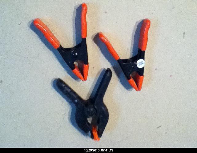

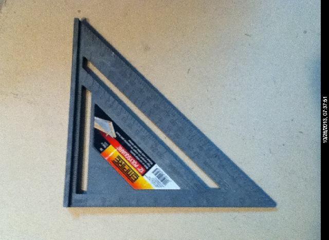

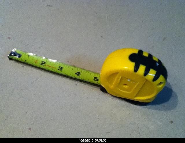
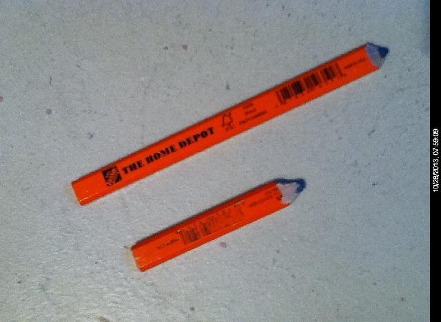
8 Typical Tools Used In The Construction Process SQUARE TAPE MEASURE JIG SAW CARPENTERS PENCIL STAPLE GUN 5/8 Brads TITEBOND 3 WOOD GLUE 5/8 BRAD NAILS WOOD SCREWS CLAMPS POWER DRILL 8
9 PANEL ASSEMLY 1. Center Bulkhead Assembly and Edge Trim (2 places) Bulkhead assembly requires that all inside edges be strengthened by applying 1x2 supports, as shown below. Use 1 screws, and glue flush to edges. Allow glue to cure. It will then be necessary to trim the outside edges of the Bulkheads to conform to the 4 degree angle of the side of the hull. To do this requires that the 2 assembled identical Bulkheads be placed face to face, as shown below. Using small clamps, secure them together, flush on all sides.. Next, mark a pencil line down one side support, 3/16 from the edge. Do the same on the opposite side of the same panel. Now, set your saw at a 4 degree angle. It is suggested you again use a saw guide, to insure a straight cut. You can then release the clamps. Mark the bulkhead with the deepest cut the Bow end bulkhead. The other is the Stern end bulkhead. Note: 1 x 2 lumber is actually 3/4 x 1-1/2 in size. And also remember, all assembled edges will receive the T&G process for complete water sealing. 3/16 inch 4 Degree Saw Cut Angle cut on each side. 1x2 supports flush to edges #6x1 Screws Fwd. Bulkhead Bulkheads Bulkhead Assembly Bolt Supports Outside edge cuts. TOP VIEW Full Size Clamped Together Rear Bulkhead Original edge The same 4 degree cut will be made on the Bow and Transom panels, below. 2. Bow, Bulkheads and Transom Panels Shown below are the Forward Bulkhead and Transom panel assemblies, constructed the same way as the above bulkheads. The Rear Bulkhead is also cut the same way. The 4 degree side angles are done as individual panels, shown below, and about 3/32 from edge. Possible transom supports for motor mount options. Fwd. Bulkhead Drawings Not To Scale Note the angle cuts Transom 1/2 Ply Remember, the good side of the plywood always faces out! 4 degree 3/32 saw cut Top View #6x1 Screws Page 9
10 REAR MODULE ASSEMLY 3. Rear Side Panels Assembly The assembly process of mounting the Side Panels to the Bulkhead and Transom is just the same as mounting the supports to the panels. Make sure the Side Panels are mounted flush to the ends of the Bulkhead and Transom assemblies, and are square to the base. See sketches. This is a good place to use the small square, shown on page 8. T R A N S O M Rear Module Check to make sure the assembly is aligned properly and flat on the floor. Inside 90 degrees Base Brads or #6 Screws Flush 4. Rear Base & Gunwale Supports Assembly Cut to length and secure the 1 x 1 base supports, as shown below, to each inside of the assembly. It is best to do this with the module upside down. Hold with clamps until cured. Trim the bottom of the Transom, if necessary. The 1 x 1's are used to keep weight down, otherwise use 1 x 2's. Use #6x7/8 screws or 5/8 brad staples. The Mini B.O.M. 2-sheets of 1/4 Plywood 2-sheets of 1/2 plywood 1-gallon of TB3 wood glue 10-1x2x8' Framing Lumber 1-box #6 x 7/8 wood screws 1-box of 5/8 Staple Brads 1-roll of Ultra-Thin Fiba-Tape NOTE : 1 x 2 lumber is actually 3/4 x 1-1/2 in size. 1 x 1's are 1 x 2's cut in half down the middle. Make from framing lumber, but be selective in your choice. Straight, few knots and dry. Supports need to be flush to all outside edges of the panels. 1 x 1 Inside Base Supports 1 x 2 Inside Gunwale Supports Trim Inside Cutaway Side View Upside Down Turn the module over, and apply the 1 x 2's to the two gunwale areas, flush to the top of the panel, per sketch at right. Allow to cure. Drawings Not To Scale Inside Recommended Support 30 Cutaway Side View Page 10
11 MODULE ASSEMLY 5. Up to this point, every assembly step was per the plans, but now you have to make the decision of what the transom area will be like for your build. The options are many, but all center around how you will power the craft, and what storage-buoyancy areas you need. The Rear Bulkhead is at the center of this decision. As designed, it encloses the rear of the hull, and provides safety buoyancy and dry storage, accessed by covered ports on the rear deck (page 3). It is also integrated strongly with the rear bulkhead and side panels. Any changes to this design will require additional structural bracing, to support the additional weight and complexity of a larger motor. OPTIONAL OPEN TRANSOM PLAN STANDARD TRANSOM PLAN Rear Deck Rear Deck Step Thru Note:Transom may have to be cut lower to fit selected motor size. See below. Motor Mount Area 16 Trolling Motor This design requires extra internal supports and motor mount cross bracing. 16 Gas Outboard 12 Support The addition of a 1/2 ply support plate is suggested for proper motor mounting. Drawings Not To Scale Note: Up to a 3-1/2 HP motor can be used, but only with proper support structure. Page 11
12 MODULE ASSEMLY 6. Rear Base Panels Assembly The Rear 1/2 Base Panels are Cut to Fit. Turn the module assembly upside down on a flat surface. Place the plywood sheet on top of the module assembly, flush to the Bulkhead, and centered, left to right (A & B), on the module. Make sure the good side A of the plywood is up (outside). See sketch below. Hold in that position, and trace both sides of the Side Panel outline on the plywood, from underneath, with a dark pencil, up to the angle break in the side panel. Mark that point on each side. Remove the panel from the assembly, and mark the break line from one side to the other. It's that easy. Then turn the panel over, and mark the break line on the inside surface, the side you will make the cut from. Cut out the Bottom panel, and lightly sand the edges to remove splinters. Now, perform the same operation on the transom Bottom Panel, but you will have to cut the ends at an angle to match the hull form, see below. Flush Plywood Panel Module Bottom Panel Break Transom Bottom Panel A B U L K H E A D B T R A N S O M Make sure the assembly is straight and true. Dimension A and B should be the same, and the panel even at the Transom end as well. NOTE: There are no cross supports on the inside of the bottom panels. The base skids, page 3, will provide additional strength to the bottom. However, if you intend to carry the maximum hull load much of the time, I suggest you use 5/8 or even 3/4 plywood for the bottom panels, for safety purposes! Next, turn the base panel over and prepare to mount to the module assembly. Align the panel carefully, after applying glue to all the module interface surfaces, and screw (#6x1 ) the panel in place starting at the Bulkhead end. Work evenly toward the transom end.. Finally, glue and screw in place the Transom Bottom Panel. Allow the assembly to cure. Now set the assembly aside, and start work on the Forward Module assembly, which is constructed in much the same way as the Rear Module, except when selecting the optional Pointed Bow. Note that we have not attempted to cut and mount a deck panel at this time. The reason is simple. Certain enclosed areas, like the inside of the motor well, will need to be waterproofed prior to the deck assembly, and depending on your build, there may be more than one area. These will be done coincident with the forward module. Page 12

13 MODULE ASSEMLY 7. It is important to note the basic steps of construction, and assembly. After the hull module sides are attached to the bulkheads, and the base panels are assembled, it will be necessary to waterproof enclosed areas prior to deck assembly, as previously mentioned. Also, it must be noted, that the inside surfaces of the deck panels must also be waterproofed, prior to mounting to the hulls. After these steps are complete, the module construction is nearly done, except for the Tape and Glue Process of all exterior seams, edges and corners. Depending on your particular build, some interior seams may also need to have T&G applied. Note that just prior to T&G, all edges and corners will need to be rounded and sanded to about ¼ inch radius. This is necessary for the fiberglass tape to properly adhere without wrinkling or puckering. For a hull this size, it will be necessary to apply 2 layers of fiberglass tape to each joint, for good strength and water protection. Once the T&G Process is complete, and all hull surfaces are sanded smooth, it will be necessary to waterproof all hull surfaces, inside and outside. The good aspect of the process I have described, is that using TB3 also strengthens the plywood, and provides a good base for Marine finishing. Radius Edges Inside 1x2 Roto-Tool with a 1/4 Radius cutter. Radius Corner Inside 1x1 1/8 4 DEGREE TEMPLATE Side Panel Radius Edge Side Panel Base Panel Typical 1/4 Radius All Corners 2 Radius Corner Typical 1/4 Radius All Edges 1-1/2 Trace and cut the template from a piece of cardboard. Use to mark Bulkhead cuts. Reference Page 9 As mentioned above, it is necessary to radius and lightly sand all edges and corners of the hull. This is so the fiberglass tape will form nicely around all corners and provide smooth surfaces. I recommend a ¼ inch radius, generated by a 1/4 router bit. These can be generated by hand and a wood file, but a router bit in a low cost high speed Roto-Tool works best. Page 13
14 FRONT MODULE ASSEMLY 8. Normally, the Front Module would be constructed in exactly the same way as the Rear Module, and no further detail would be necessary. However, for the purpose of defining one of the hull options, the detail shown below will be of the Pointed Bow. There are basically 3 steps to creating the pointed bow. Cut 2 lengths of 1x2's and glue them together. Next, cut the ends to fit the Bow, as shown in Sketches 1 & 2, and glue and screw to the inside of one of the side panels. This is the Bow Block. Sketch 1 - Top View Bow Block The next step is mounting of the side panels to the Center Bulkhead, just as you did for the Rear Module, Sketch 3.. The final step will be to bring both side panels together, glue and screw, as shown below in Sketch 4. This may require the use of a strap wrapped tightly around the outside length of the module, and a spacer bar, to hold the hull's desired shape. Depending on where you want the Forward Bulkhead, the side shape can be enlarged slightly by wedging the bulkhead in place. Builders option. 1x1 Base and Gunwale Supports Sketch 2 Side View Remember, good side of plywood is on the outside of the hull. Optional Temporary Spacer Bar Sketch 3 - Mounting Sketch 4 - Assembly Note: The Bow Block could be made from 1x1 lumber, but more difficult to mount. The nose will be rounded after the base assembly. Drawings Not To Scale The next step will be to add the Forward Bulkhead and the Internal 1x1 Edge Supports, but the process is more involved than was used on the Rear Module. See the next page for detail. After the bulkhead and supports are assembled, the Base Panel will be installed, in the same manner as the rear module, and any enclosed space will be waterproofed. Finally, the deck will be secured in position. Page 14

15 FRONT MODULE ASSEMLY 9. After the module Pointed Bow is secure, it is time to consider what kind of Forward Bulkhead you will use to complete the Forward Module design. The bulkhead drawn is intended to keep the forward portion of the hull enclosed, and act as a safety buoyancy cell. With a removable port cover, it can also become a watertight dry storage area. However, the choice is yours. An option could be to have an upper and lower cross beam support, to maintain the hull shape and strength, and leave the forward portion wide open, for quick access to gear and equipment stored beneath the deck. The following sketches depict the enclosed version. It's important for you to note that the bulkhead can be placed almost anywhere, and at any angle. However, to allow good seating, it should be placed about 30 inches from the center bulkhead. Once you have made this decision, placement of the kerffed side supports can begin. See the sketch directly below. Optional 1x2 support Forward Bulkhead Kerffed Supports 1x1 supports Approx. 30 It bears repeating, if you are not building the Pointed Bow version, construct the Front Module just as you did the Rear Module. 10. The primary difference between the two versions is the curved side panels. In the straight version, 1x1 supports are easily cut and bonded to the bottom edges and the upper edges of the module, to which the base and deck are bonded. The same is required of the curved side panels, but the supports have to be kerffed, in order to bend to the rounded surfaces. Kerffing is the process of cutting saw blade width slots in the support, at equal intervals, to allow the support to conform to the shape of the side panels, and still provide panel strength. For this application, refer to the sketches below. It is important you do not cut through the support, and that the spacing is reasonably consistent. The supports are glued in place, and can be secured with screws or spring clamps, until cured. 3 3/16 This is the Kerf cut by a hack saw blade on the 1x2 support. Typical KERF saw cuts Page 15
16 FRONT MODULE ASSEMLY 1/2 Ply Base Panels 11. Mark, cut and fit the base panels just as you did for the Rear Module assembly. Depending on the Forward Bulkhead design chosen, you may have to Waterproof the forward compartment. Refer to the process on the next page. Forward Compartment Note: If you decide to make the Rear base panels of a thicker material, you should also make the Forward base panels the same thickness. Waterproof Forward Compartment Page Now that you have completed the waterproofing of the forward compartment, it's time to install Deck Panels. I used the plural because we will do both modules at the same time. These are also Fit at Assembly panels, so they must be measured and cut to size. Again, depending on your build, the decks should at least enclose the Buoyancy Cells. Extending the forward deck is suggested for appearance and to minimize water intrusion. See deck examples on page 7. Remember, the inside of the deck panels must be waterproofed prior to installation. Another option is a forward module cuddy-cabin, for increased protection. Rear Deck Buoyancy Cell Forward Deck Buoyancy Cell Once the decks are installed, it is important that all the edges have a radius applied, and all interior surfaces receive a light sanding. Then you can waterproof the inside of both modules, but only the inside. The next step, defined on page 18, is the Tape and Glue Process, page 18, of all the external seams and edges. As mentioned earlier, two layers of tape are necessary for this hull, so take your time and do a good job. Once the T&G is complete, and cured, other additions, such as 1x2 Gunwale Rub-Rails and Seat Supports, can be installed, as well as the 1x2 Skids on the bottom of the hull (page 26). Page 16
17
18
19
20
21
22
23


24 PHOTO REVIEW These photos are from a different but similar build. Note the simplicity of construction, and ease of assembly. Pictures of the F.I.T., built by Greg Bowles, Ontario Canada. All bulkheads and upright panels assembled. Relative position layout of the panels You should also notice the simple lines of the hull, all straight cuts, no curves. Improves the build time and reduces possible errors. Rear module bulkheads and side panel assembly Forward module bulkheads and side panel assembly Page 24


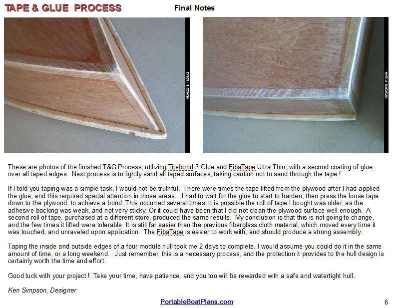
25 PHOTO REVIEW The rear module fully assembled, with taped seams and edges. Note motor mount panel on transom. Forward deck with twist-off hatch installed. The forward module, also completely taped. Note the addition of the deck with an access hatch opening. Rear module bottom with epoxy and fiberglass covering. The next steps will be the installation of the bottom skids, painting and accessories. Page 25

26 If, for any reason, you do not wish to use the T&G Process for sealing all seams and edges, you can revert to the more traditional method of 1x1 inside corner stringers, as described in the sketch at right. This can be more work, but will provide you with the necessary hull security desired. What it lacks is plywood edge sealing, which the T&G provides. So, if you do employ the edge stringer method, I strongly suggest you at least fiberglass the outside seams, to prevent water penetration into the plywood. Page 26
27 STEP 13 The gunwale rub rails are a good addition for hull security and side rigidity. Some may want to add similar 1x1 rails along the water line, or chine area, for additional hull protection, prior to full hull waterproofing.. Optional Decking Optional 1x2 Rub Rails Shaded lines represent all T&G corners and edges. In case you have forgotten, now is the time to completely WATERPROOF the entire inside and outside of the hull modules, page 17. Then sand lightly all waterproofed surfaces in preparation for the final marine finishes. 8 1x2 Skids On Center Bottom View Note: The skids are glued, and then screwed to the base from inside, using #8 x 1-1/4 flat head wood screws, stainless steel preferred. After the skids are complete it will be necessary to round all edges, and waterproof them. The next step is to finally join the two hull modules together, using 3/8 inch diameter bolts. See the following pages. Page 27

28 ASSEMBLY BOLT HOLES & HARDWARE STEP 14 Assembly Bolt Knob See drawing on next page. Bolt length to be 3-1/2 inches Page 28

29 STEP 15 Page 29


30 FINAL REVIEW This is the point where you stand back and look at your creation, and decide what kind of finish to apply, and what colors. Just remember, the outside of the hull gets the most abuse, so select finishes that are marine rated, such as Marine Spar Varnish, like the boat shown below, or Marine Epoxy Paint. House paints are not recommended. Also, a heavy duty finish on the floor is recommended, to minimize wear. Some people use a spray-on truck bed-liner material. Again, your choice of materials and finishes is what makes your boat unique. Pictures of a similar boat, the F.I.T., built by Greg Bowles, Ontario Canada. Finally, it is important to customize your boat to meet your specific needs and expectations. This can include anything from a full canopy top, to an internal raised platform for overnight sleeping. Fishing pole holders, like in the photo above, make for easy fishing while under power. One area of caution is not to place anything on the hull that would prevent nesting of the modules, or that could become damaged in transport. Good luck with your build, and make sure you practice safe boating. The original goal of this particular design was to provide a hull that could be many things to many people. By constructing a boat that does what you want it to, rather than what the designer thinks you want, delivers a powerful message. Home builders often have dreams of the ideal boat, but most of the time have to make compromises, because their dream boat just does not exist. With this U2 Hullz concept, you can make it just the size, shape and function you desire. In retrospect, I think the goal has been achieved. Sincerely, Ken Simpson, Designer Page 30
An Easy to Make, Paddle and Transport Family Pram. Print in Landscape Mode with ¼ inch borders. Adult Figure Shown
 An Easy to Make, Paddle and Transport Family Pram Drawn 05-10-2013 Rev. 06-21-2014 Print in Landscape Mode with ¼ inch borders. FEATURES: Ultra-Stable Wide Design Simple Flat Side Construction Only 2 Sheets
CPB-1 Lightweight Folding Pram
 Lightweight Folding Pram An ultra-lightweight folding pram, only 15 pounds. Ideal for the lone fisherman or paddling enthusiast. Easy to make and fits in any vehicle when folded! See the hull and load
A great weekend getaway vehicle for the lone sports man or woman. Print in Landscape mode, with 1/4 borders. Optional Enclosure or Full Canopy
 A great weekend getaway vehicle for the lone sports man or woman. Drawn 04-21-2013 Rev. 9-11-2016 ken simpson designs Print in Landscape mode, with 1/4 borders. This is the baby sister to the Mini CAMPER
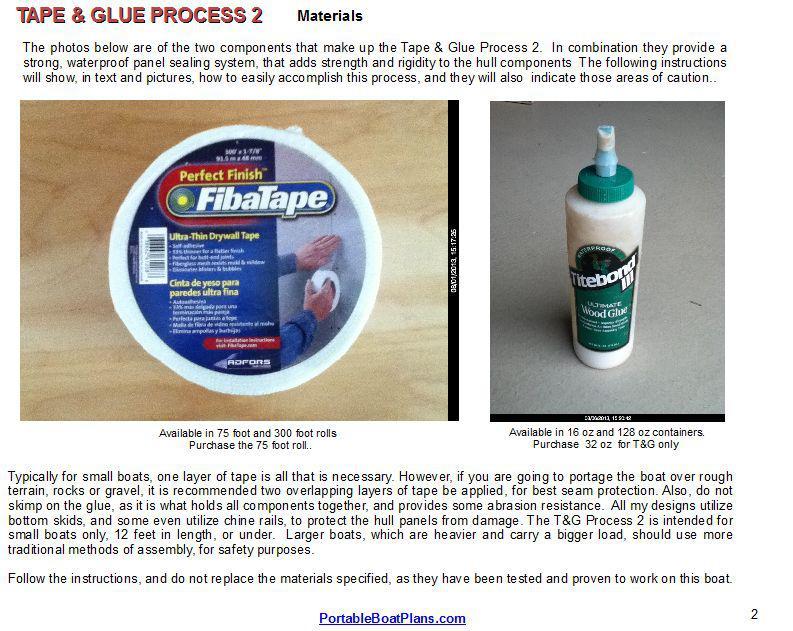
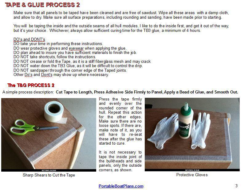
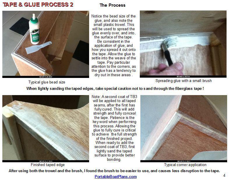
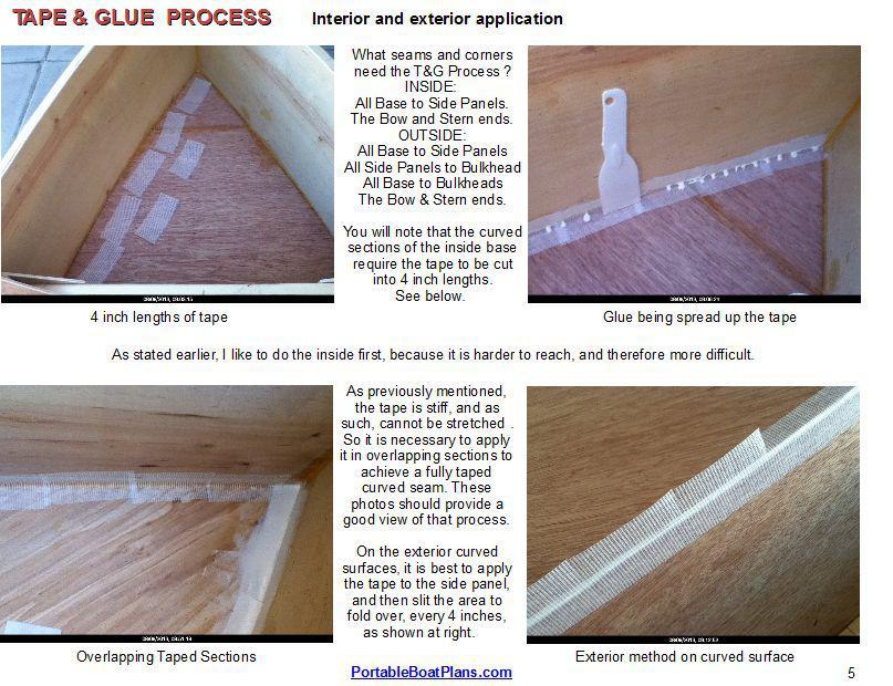
TAPE & GLUE PROCESS Version: Jun. 2011
 FREE to print TAPE & GLUE PROCESS Version: Jun. 2011 The following small boat assembly process was developed out of the need for an easy, lightweight, cost effective and health friendly method of providing
MODULAR PDRacer. A more portable version of the famous Puddle Duck Racer. Ken Simpson, Designer
 A more portable version of the famous Puddle Duck Racer. MARCH 2011 32 Pages After much deliberation, I have decided to provide a new version of the Puddle Duck Racer for those that have requested a more
Photo Essay Building a. Key Largo. Carolina Dory. Plans for this boat may be found at:
 Photo Essay Building a Key Largo Carolina Dory Plans for this boat may be found at: http://spirainternational.com/ Photo Essay Building a Key Largo Carolina Dory The Carolina Dory is a specialized type
Use these notes in conjunction with the plans and the plan's building notes.
 GF18 CNC kit notes. Use these notes in conjunction with the plans and the plan's building notes. The standard kit is based on the GF18 with the sole option, central bench included. There are small differences
Photo Essay How to Build an. Alaskan. Grand Banks Dory. Plans for this boat may be found at:
 Photo Essay How to Build an Alaskan Grand Banks Dory Plans for this boat may be found at: http://www.spirainternational.com/ How to Build an Alaskan Grand Banks Dory The Alaskan is an easy to build Spira
Bateau.com PH18 CNC kit notes 1/5
 Bateau.com PH18 CNC kit notes 1/5 These building notes must be used in conjunction with the standard building notes included in the plans package for this boat. The PH18 kit is assembled as described in
Cowper From Steve Wolverton on the T&TTT forum, Feb 2005 For Reference Only Do not use to build a trailer. Check on Teardrop and Tiny Travel Trailers
 Cowper From Steve Wolverton on the T&TTT forum, Feb 2005 For Reference Only Do not use to build a trailer. Check on Teardrop and Tiny Travel Trailers for up to date building information; http://www.mikenchell.com/forums
Above are the offsets for the plywood panels.
 DinkyDink Plans Bottom Panel Half Station X Y X2 Y2 1 1/4 3/4 0 11 5/16 2 4 9/16 4 12 9/16 3 11 11/16 1/4 11 7/16 14 1/2 4 18 5/8 1/16 18 5/8 15 11/16 5 25 3/4 0 25 3/4 16 5/16 6 32 13/16 0 32 13/16 16
Seamed Undermount Bowls
 CUTOUT TEMPLATES MAKING CUTOUT TEMPLATES 7.1 CUTOUT TEMPLATES The use of an accurate template is one of the most essential elements to the successful completion of a cutout in Corian. For the completion
Wood Duck Nest Box Design & Assembly Directions
 Wood Duck Nest Box Design & Assembly Directions Instructions, Illustrations & Photos Courtesy of MWDI and Scott Jasion, Harford County Chapter, Ducks Unlimited Side door opening design for easy mounting
More Storage Space Under Yacht Bed
 More Storage Space Under Yacht Bed Open up storage space under your bed! Convert your bed deck to a Lifting Hatch with Gas Spring assist! Many bed decks on boats and RV s have two or three pieces of plywood
Building Tips This model can be built using the following types of adhesives:
 Page 1 Building Tips This model can be built using the following types of adhesives: Epoxy (with or without microballons) Odorless cyanoacrylate (CA) with accelerator UHU Creativ for Styrofoam (or UHU
Wanderlust Suitcase Vanity
 Wanderlust Suitcase Vanity If you re like me, you re always up for an adventure. When I saw some examples of DIY reclaimed suitcases, paired with the exciting new Wanderlust embroidery design collection,
Illustrated Guide to Building a Spira International Ply on Frame Boat
 Illustrated Guide to Building a Spira International Ply on Frame Boat Spira International, Inc. Huntington Beach, California Copyright, 2008 All Rights Expressly Reserved Building a Spira International
Hatch Installation For Pygmy Solo and Double Kayaks
 Introduction/Overview Hatch Installation For Pygmy Solo and Double Kayaks The hatch kit consists of several wooden lips, strapping and hardware. The hatch is constructed by cutting a hole in your deck,
Building Instructions Diva cabin boat
 Building Instructions Diva cabin boat Order no. 3093/00 aero-naut Modellbau Stuttgarterstr. 18-22 D-72766 Reutlingen / Germany http://www.aero-naut.com 1 For pictured building instructions please see the
A Skin-on-Frame Pram. Designed by Dana Munkelt. Drawings by Andrew Walters. Duckworks Boatbuilder's Supply duckworksbbs.com
 A Skin-on-Frame Pram Designed by Dana Munkelt Drawings by Andrew Walters Duckworks Boatbuilder's Supply duckworksbbs.com "" is a small skin-on-frame (SOF) pram design with a twist; a solid plywood floor.
Pivot-Door Downdraft Cabinet Plans
 Pivot-Door Downdraft Cabinet Plans Finished Cabinet Closed Open Exploded View Introduction This simple downdraft-style dust collection cabinet is a great way to keep your shop cleaner and keep your router
The image above is intended to give you an idea of what the dovecote will look like when finished.
 Thank you for buying my book, I hope it is useful and enjoyable in your quest to building your own dovecote. This book will give you step-by step instructions on how to build your own dovecote also included
Delfini. 19x6 Console Semi Flat Hull. Study Plans
 Delfini 19x6 Console Semi Flat Hull Study Plans Contents 3 Introduction 4 Specification 6 List of Materials 7 Glue, Resin and Fixings 8 Tools 9 Construction Sequence 2 Introduction This is the 19' x 6'
Chapter 23. Garage Construction
 Chapter 23. Garage Construction 23.1 ESTABLISHING CHALK LINES 23.2 MEASURING AND CUTTING WALL PLATES 23.3 MARKING WINDOW & DOOR LOCATIONS ON EXTERIOR WALL PLATES 23.4 MARKING STUDS ON EXTERIOR WALL PLATES
 America s leading woodworking authority To download these plans, you will need Adobe Reader installed on your computer. If you want to get a free copy, visit: http://adobe.com/ reader. Having trouble downloading
GENERAL NOTES: Page 1 of 9
 Laminating A Zia Into A Turning Blank by W. H. Kloepping, Jan. 2009 This describes how a zia (the New Mexico state symbol) can be laminated into a turning blank. Materials needed: Square Turning Block
Chapter Six. Getting started inboard. Installing the false deck
 A close look at the thinning down of the bulkhead extensions. They are just 1/16 thick after fairing them. Chapter Six Getting started inboard This next step is one of the last remaining messy tasks to
PoorBoy Skiff. A 10-11ft 6in skiff for outboard motoring By Steven Lewis
 PoorBoy Skiff. A 10-11ft 6in skiff for outboard motoring By Steven Lewis PoorBoy is about the simplest small motorboat you will come across. It consists of 2-2 1/4 sheets of plywood (1-1 1/4 sheets x3/8
Installation Instructions for Siding
 Smart-Shingle TM System "The new smart way to install cedar shingles." - This Old House Installation Instructions for Siding V3.2 INSTALLATION GUIDE MARKS Shingle-Strip 0 1 2 3 4 5 6 7 8 9 10 11 12 13
A Day House. A View of One Way to Finish the Exterior of The Day House. Read these instructions all the way through before beginning this project.
 A Day House A View of One Way to Finish the Exterior of The Day House Read these instructions all the way through before beginning this project. General Comments For the purposes of this project, the standard
BUILDING A STORM DOOR
 BUILDING A STORM DOOR BY NEAL BARRETT Illustrations by George Retseck If you're in the market for a storm door, you probably know that there are many styles and models available. However, most of them
96 WING SPAN SPITFIRE (COPYRIGHT PROTECTED 2014) ALL RIGHTS RESERVED
 ALL RIGHTS RESERVED") 96 WING SPAN SPITFIRE (COPYRIGHT PROTECTED 2014) ALL RIGHTS RESERVED GENERAL INSTRUCTIONS Should you elect to use the recommended Door Skin, which is 1/8 mahogany plywood measuring 36 x 88. Have it cut
96 WING SPAN SPITFIRE (COPYRIGHT PROTECTED 2014) ALL RIGHTS RESERVED GENERAL INSTRUCTIONS Should you elect to use the recommended Door Skin, which is 1/8 mahogany plywood measuring 36 x 88. Have it cut
Empire Dresser Plans
 1 Empire Dresser Plans Materials 1 sheet 3/4" plywood (cabinet grade 4' x 8') 1 sheet 5 mm (3/16") underlayment plywood 4'x 8', buy another 1/2 sheet if you want to put a back on the dresser. 1-2" x 4"
Building a Scarab 350 Trimaran
 This boat was designed to be built using flat panels. In either foam laminated panels or plywood. 1. The build time is less. Panels are lofted, cut out and joined on the frame. 2. Frame can be simpler.
3Insert the second rod no. 4
 Yamato: Step-by-step 37 The stern block and searchlight control towers a b c d e f Recommended tools and materials Wood glue Sandpaper (no. 800 grain) Metal file Putty Craft knife For metal: Super Glue
Kitchen Upper Cabinet: Double Doors Cabinets from Scratch
 Kitchen Upper Cabinet: Double Doors by Cabinets from Scratch Our Home from Scratch LLC Page 1 Disclaimer Our Home from Scratch LLC and its legal owners cannot be held responsible for any loss, damage,
Build a Bluebird Nest Box
 Design by Lee Pauser webmaster@birdsfly.info Graphics by David Altknecht The contents of this plan cannot be used for commercial purposes. Non-commercial endeavors may use the plan as long as it remains
Copyright 1998 KDE Technologies
 Modular Computer Corner Desk Unit Copyright 1998 KDE Technologies http://members.tripod.com/~kdetech/ 1. Introduction 2. Plans Sheet one - Isometric Sheet two - Top Detail / Corner Unit Sheet three - Leg
AN IMPROVED DESIGN FOR AMATEUR BUILDERS.. TAKES SAIL OR MOTOR
 BUILDING A General H ERE is a rowboat that is in a class by itself the final development of a long line of forerunners. This graceful little V-bottom craft is 13 ft. long, carries from four to six passengers,
ULTIMATE ROUTER TABLE PLANS. By Dan Phalen
 ULTIMATE ROUTER TABLE PLANS By Dan Phalen January 2017 Ultimate Router Table Plans. Copyright 2012-2017 by Daniel Phalen. Published by Creston Hall Publishing Company. All rights reserved. No part of this
T3500 #131 Sole Repair & Re-setting. Adding Access to the Hidden Bilge
 Purpose: 1. To repair a damaged portion of the holly/teak veneered plywood sole by the mast base and provide ventilation and drainage between the sole and the fiberglass sub sole. 2. To install a new hatch
Continue gluing the remaining top parts ensuring the angled piece is glued well. Set aside and let dry. See photo below
 Radiator rev 1.1 The SE5a s radiator is one of the most recognized radiators in WW1. It is one of the components that defines the SE5a. The original SE5a has seen multiple radiator designs used during
Piper Cherokee /3 scale. Construction Manual
 Piper Cherokee 140 1/3 scale Construction Manual STAB CONSTRUCTION 1. Remove foam cores from cradle and place on flat surface. Inspect pieces before you epoxy halves together making sure leading and trailing
1Use the metal file to smooth
 Yamato: Step-by-step 85 Parts of the bridge and the hull a b c d e f a Part of the bridge b Part of the bridge c Part of the bridge d Radar x 2 e Part of the bridge x 2 f Wire Recommended tools and materials
COMPLIMENTARY WOODWORKING PLAN
 COMPLIMENTARY WOODWORKING PLAN COFFEE TABLE PLAN This downloadable plan is copyrighted. Please do not share or redistribute this plan in any way. It has been paid for on your behalf by JET Tools, a division
FUSELAGE CONSTRUCTION
 FUSELAGE CONSTRUCTION Note: prior to building and gluing on the work surface use protective covering on your building surface. (wax paper or clear wrap) Fit the laser cut Fuselage Front and Fuselage Rear
woodworkersjournal.com MATERIAL LIST
 MATERIAL LIST T x W x L 1 Legs (2) 1 1 2" x 3 1 2" x 36 7 16" 2 End Uprights (2) 1 1 2" x 3 1 2" x 32 1 2" 3 Stringers (4) 1 1 2" x 3 1 2" x 42" 4 Top Cladding, Long (2) 3/4" x 7 1 4" x 65 3 4" 5 Side
Contents. Introduction. List of Materials. Glue, Resin and Fixings. Tools. Construction Sequence. Study Plans Sheet 3. Andrew Walters April 2012
 Mia Study Plans Contents C Andrew Walters April 2012 2 Introduction. 4 List of Materials. 5 Glue, Resin and Fixings. 6 Tools. 7 Construction Sequence. 10 Study Plans Sheet 1. 11 Study Plans Sheet 2. 12
Building Instructions
 Building Instructions Tools Required Tape measure Straight edge Pencil/pen Jigsaw Table Saw Circular Saw Electric drill 1 Hole saw bit Saw horses/table Protractor Staple gun Caulk gun Paint brush Wrenches
How to build a Javelin Skiff
 How to build a Javelin Skiff This is not your grandfather s plywood boat! The Javelin involves a high-tech type construction, called composite. The hull can be constructed with foam or plywood; these materials
SE5a Wing Panels rev 1.0
 SE5a Wing Panels rev 1.0 The top and bottom wings are different. They might look the same but the bottom wing has one less rib and some rib spacing difference. This is due to where the wooden interplane
Penobscot 14 Building Log
 Penobscot 14 Building Log Date July 26, 2004 Duration Activity plane jig boards July 27, 2004 July 28, 2004 cut jig boards cut frame boards, assemble jig July 29, 2004 6.75 hr assemble jig August 2, 2004
Corner Entertainment Center Plans
 Table of Contents Introduction... 3 Let s discuss the tools needed... 3 Let s discuss the materials needed... 4 Let s build it... 4 Attaching the 2x2's... 7 Determine the shelf spacing... 9 Scribing the
Small Town Buildings. Scaled and easy to read patterns and instructions. Shoe / Western Union (with and without porch)
") 1 /24 th Scale Patterns kiva design G R O U P E 1 Story Flat Roof Yard and Garden Buildings Compatible with Garden Railroads or a delight for any child's collection Overall Dimensions Foundation: 10" x
1 /24 th Scale Patterns kiva design G R O U P E 1 Story Flat Roof Yard and Garden Buildings Compatible with Garden Railroads or a delight for any child's collection Overall Dimensions Foundation: 10" x
Building instructions ARTEMIS Sailing Canoe Day Five Version 1.0 Brian Pearson & Dr. Axel Schmid Day Five. Assembly of Planks and Frames
 Building instructions ARTEMIS Sailing Canoe Version 1.0 Brian Pearson & Dr. Axel Schmid 2016 Assembly of Planks and Frames Steps: Assembling hull plansk with wire Install frames Align and check keel rocker
SE5a Instrument Board part 2 - rev 1.1
 SE5a Instrument Board part 2 - rev 1.1 Fuel (Petrol) Valve This valve uses two circular name plates, eight brass screws, one black plastic base, copper wire and two black plastic risers. You can pick any
Beds may be put up or taken down quickly by use of a simple bolted connection at rails and uprights. MATERIALS LIST
 CANPLY This design has been made both functional and attractive by use of pattern cut-outs in head and foot uprights, which serve as ladders. Since most children love to climb, getting them to bed will
Installing your new Bevella Top. L Shaped Countertop with Joints No Finished Ends (Fits Between Four Walls)
") Installing your new Bevella Top L Shaped Countertop with Joints No Finished Ends (Fits Between Four Walls) Bevella RTI Countertops are engineered and manufactured to the highest quality standards, built
Installing your new Bevella Top L Shaped Countertop with Joints No Finished Ends (Fits Between Four Walls) Bevella RTI Countertops are engineered and manufactured to the highest quality standards, built
Cardboard Cup Regatta Plans and Directions
 To help celebrate the upcoming Crystal Lake America s Cardboard Cup Regatta, we have asked a veteran of 18 races to submit a set of plans and directions to build an unsinkable and competitive cardboard
ALIEN ENCLOSURES CAMARO AND FIREBIRD Trunk Panel Kit Instructions
 ALIEN ENCLOSURES 67-69 CAMARO AND FIREBIRD Trunk Panel Kit Instructions TYPICAL TOOLS & MATERIALS NEEDED FOR UPHOLSTERY 2 Yards of Main Panel Material 1.5 Yards of Backer Material 3 yards of foam backing
Part 2 Lining off and planking
 Part 2 Lining off and planking Lining off the hull for planking Those of you who have built one of my projects in the past probably know how I have always stressed the importance of lining of your hull.
FORWARD FUSELAGE SIDES & REAR TOP SKINS
 FORWARD FUSELAGE SIDES & REAR TOP SKINS WORK REPORT Step No. Check Parts / Tools Qty Preparations. 1 [ ] 6F5-3 Upper Front Longerons 2 2 [ ] 6F5-5 Heel Support 1 3 [ ] 6F5-2 Front Floor Skin 1 3 [ ] Firewall
Kitchen Step Stool. Premium Plan. In this plan you ll find: America s leading woodworking authority
 America s leading woodworking authority Premium Plan In this plan you ll find: Step-by-step construction instruction. A complete bill of materials. Construction drawings and related photos. Tips to help
Tools and Tips: ( 1 )
") Tools and Tips: As you build instructions will show in my many picture manual how to assemble. You can use your own methods as you desire, my results are very good. A smooth, flat work surface is very
Tools and Tips: As you build instructions will show in my many picture manual how to assemble. You can use your own methods as you desire, my results are very good. A smooth, flat work surface is very
FireFighter.21 Building Instructions
 A Tom Moorehouse design. Thank-you for purchasing the FireFighter.21. I believe that you will find it to be the best.21 rigger kit available. It has won 1 st place in the 2006 AMPBA nationals! It was designed
Tools and Tips: ( 1 )
") Tools and Tips: As you build instructions will show in my many picture manual how to assemble. You can use your own methods as you desire, my results are very good. A smooth, flat work surface is very
Tools and Tips: As you build instructions will show in my many picture manual how to assemble. You can use your own methods as you desire, my results are very good. A smooth, flat work surface is very
Balustrade Systems / Installation Instructions
 A. PARTS AND SUPPLIES NEEDED FOR INSTALLATION Hardware included for each 10 section of rail: 2 3 x 1-1/2 L-brackets 4 1-3/4 x 3/16 Blue hex-head screws for anchoring the L-brackets to the newel cap, column
Building Instructions ARTEMIS Sailing Canoe Day Six Version 1.0 Brian Pearson & Dr. Axel Schmid Day Six. Align and Glue Planks
 Version 1.0 Brian Pearson & Dr. Axel Schmid 2016 Align and Glue Planks Steps: Align boat, check dimensions Join planks provisionally Pull wires Glue the outside planks Tools and Materials: Epoxy putty
CENTER WING SECTION (CWS) WORK REPORT
 WORK REPORT") CENTER WING SECTION (CWS) WORK REPORT No. Check Parts / Description Qty PHASE 1: Preparations 1 [ ] 6V1-3 Rear ribs 2R & 2L 1 [ ] L Angle 6 2 [ ] 6V2-1 Rear Ribs.032 2R & 2L 2 [ ] 6V5-1 Gear Rib Doubler
CENTER WING SECTION (CWS) WORK REPORT No. Check Parts / Description Qty PHASE 1: Preparations 1 [ ] 6V1-3 Rear ribs 2R & 2L 1 [ ] L Angle 6 2 [ ] 6V2-1 Rear Ribs.032 2R & 2L 2 [ ] 6V5-1 Gear Rib Doubler
Motorcycle Lift Assembly Instructions
 Motorcycle Lift Assembly Instructions Copyright JCS 2009 Rev1M Page 1 Lift Table Assembly Instructions The following pages will assist you in the construction of your Motorcycle Lift Table. You will find
Cardboard Model Buildings
 Cardboard Model Buildings Get more model kits from http://www.modelbuildings.org PRINTING & ASSEMBLY TIPS: These OO designs can easily be resized by reducing the print percentage as follows: OO scale is
INSTALLATION INSTRUCTIONS
 INSTALLATION INSTRUCTIONS BUILDERS CHOICE FRAMED Bypass Door Model: L0516 (Tub Height), L0517 (Shower Height) Rev. 09.20.13 INSTALLATION NOTES: Unpack your unit carefully and inspect for freight damage.
Safety First! Use eye protection, always! Use ear protection with loud power tools. Stay with children while they work!
 TM TM ART TABLE Safety First! Use eye protection, always! Use ear protection with loud power tools Stay with children while they work! Follow tool manufacturers safety guidelines Page 1 ART TABLE Page
Case Building Instructions For Derbywizard Freedom Aluminum Tracks
 Case Building Instructions For Derbywizard Freedom Aluminum Tracks You can easily build a hard storage case for your new track by following these simple instructions. Materials Case Width (W): 2 ln = 8.75",
Frameless Inline Door With Return QCI5263
 INSTALLATION INSTRUCTIONS Frameless Inline Door With Return QCI5263 WALL MOUNT HINGES FRAMELESS DOOR / PANEL / RETURN PANEL QCI5263 REV. 0 Page 1 Certified 06/17/2016 Parts List with wall mount hinges
Display Case (for J&S)
") Display Case (for J&S) This is constructed of maple plywood with solid maple (soft maple) edge banding. It was made to fit between a door and a kitchen cabinet, and has an elegant circular taper between
Display Case (for J&S) This is constructed of maple plywood with solid maple (soft maple) edge banding. It was made to fit between a door and a kitchen cabinet, and has an elegant circular taper between
Australian Vintage Radio Society Inc.
 Australian Vintage Radio Society Inc. (Incorporated in Victoria A0050003S) P.O. Box 3099, Syndal L.P.O., Victoria, 3150, Australia. Cabinet assembly instructions for the AVRS 10 th Anniversary construction
SAN FELIPE: Step by Step Pack 2
 Pack 2 Your parts Stern reinforcement Bulkheads The poop deck Bulkhead planks Planks Tools and equipment Knife Pencil Wood glue Sandpaper File a Using leftover 5 x 5-mm wooden strips, measure and cut beams
The Festival Assembly Instructions
 The Festival Assembly Instructions Toll Free: 866.768.8465 Hours: 9-5 Monday-Friday EST www.homeplacestructures.com Package ships as shown CONTACT INFORMATION: HomePlace Structures 301 Commerce Drive New
TM TM DOG HOUSE Age 9+
 TM TM DOG HOUSE Age 9+ Safety First! Use eye protection, always! Use ear protection with loud power tools Stay with kids while they work! Follow tool manufacturers safety guidelines This project is recommended
Plans. Easy-to-Build Full-size Deluxe Murphy Bed Plan. For more plans, tools and hardware visit rockler.com
 Easy-to-Build Full-size Deluxe Murphy Bed Plan Build a full-size Deluxe Murphy Bed complete with decorative molding and matching side cabinets! Plans For more plans, tools and hardware visit rockler.com
PAT installation of a Sun Dome over a in-ground
 PAT. 3766573 Installation of Sun Domes for in-ground pool GENERAL INSTRUCTIONS: STEP 1. Read thru the entire instructional materials before beginning any installation. You will find that the installation
Phase Two. The Skirt, Play Area and Sub Table ( continued )
") Dry fit the skirt in place and make sure all is tight. Drill a countersink screw hole on the back of the skirt down where you will connect it to the bull nose. Make three holes on each board (ends and
Dry fit the skirt in place and make sure all is tight. Drill a countersink screw hole on the back of the skirt down where you will connect it to the bull nose. Make three holes on each board (ends and
Contents. Study Plans. 2 Introduction. 4 List of Materials. 5 Glue, Resin and Fixings. 6 Tools. 7 Construction Sequence
 Volare Study Plans Contents 2 Introduction 4 List of Materials 5 Glue, Resin and Fixings 6 Tools 7 Construction Sequence Study Plans The study plans consist of an abridged version of the first 7 pages
INSTALLATION INSTRUCTIONS. UNIT No. 160/760 THIN-LINE SHOWER ENCLOSURE
 INSTALLATION INSTRUCTIONS UNIT No. 160/760 THIN-LINE SHOWER ENCLOSURE QCI0011 Rev. 0 Page 1of 10 Certified 10/18/2006 MAINTENANCE: Two primary materials are used to manufacture your new Basco enclosure;
Instructables Butcher Block Top
 Instructables Butcher Block Top Project Overview: This project requires basic woodworking skills and access to woodworking machines. Woodworking machines have sharp cutting edges and are NOT forgiving.
Redwood strips are tacked to the templates, and edge-glued. Drive brads through into the templates before putting on fiberglass doth.
 1 Make the building form and attach templates to the crosspieces. Nail a strip down the center to hold the stems and templates in position. prototype canoe took about three weekends to build. She's broad
Frameless Inline Door QCI5248
 INSTALLATION INSTRUCTIONS Frameless Inline Door QCI5248 FRAMELESS PANEL / DOOR / PANEL QCI5248 REV. 0 Page 1 Certified 06/16/2016 Parts List with glass to glass hinges *Quantities may vary. **Support Bar
Continuous Hinge Frameless Single Swing Shower Enclosure QCI-5214
 INSTALLATION INSTRUCTIONS Continuous Hinge Frameless Single Swing Shower Enclosure QCI-5214 QCI5214 Rev. 1 Page 1 of 8 Certified 09/19/18 MAINTENANCE: Two primary materials are used to manufacture your
U. M. ARMY Texas Conference. Wheel Chair Ramp Manual
 U. M. ARMY Texas Conference Wheel Chair Ramp Manual June 2014 U. M. ARMY Texas Conference Building & Repair Tips Wheelchair Ramps Complete a site survey to determine the design and layout of the ramp.
MLCS Instructions for Bowl and Tray Template Kit #9176/#9179
 MLCS Instructions for Bowl and Tray Template Kit #9176/#9179 Tools Needed: Router 1-1/2 h.p. Minimum recommended with a 1/2 collet Forstner bit 3/4-2 recommended depending on template used Drill Press
Hull Modifications. General Introduction
 Hull Modifications General Introduction The living quarters for the Captain consisted of the Great Cabin, used for daily activities; Stateroom, used as sleeping quarters and the Coach Cabin, which in larger
PLANS BY KELLEY FARMHOUSE DESIGNS LOFTED DORM ROOM BED
 PLANS BY KELLEY FARMHOUSE DESIGNS LOFTED DORM ROOM BED DIMENSIONS: 82" X 70" X 45" DIFFICULTY LEVEL: INTERMEDIATE TOOLS REQUIRED ONE+ Circular Saw ONE+ AirStrike 16GA Finish Nailer ONE+ Impact Driver ONE+
Nanton Grain Mill Assembly
 ( 1 ) Nanton Grain Mill Assembly Locate package for assembling storage building. These are cut from 1/8 masonite. Inspect and lightly sand edges where it will be bonded. Use white glue or CA glue to bond.
A WORD ABOUT BRACING PART A - BUILDING A STRAIGHT, PILE BENT, OPEN DECK TRESTLE. Built in Place, Straight
 BUILDING LARGE SCALE TRESTLES You have many options when building a large scale trestle. The choices you make may be based on the prototype you are modeling; the era or industry you are modeling; or, simply
INSTALLATION INSTRUCTIONS FRAMELESS CONTINUOUS HINGE SHOWER ENCLOSURE QCI5233
 INSTALLATION INSTRUCTIONS FRAMELESS CONTINUOUS HINGE SHOWER ENCLOSURE QCI5233 QCI5233 Rev 0 Page 1 Certified 06/20/2016 INSTALLATION NOTES: Unpack your unit carefully and inspect for freight damage. Lay
Kitchen Base Cabinet: Multiple Drawers Cabinets from Scratch
 Kitchen Base Cabinet: Multiple Drawers by Cabinets from Scratch Our Home from Scratch LLC Page 1 Disclaimer Our Home from Scratch LLC and its legal owners cannot be held responsible for any loss, damage,
MAGNUM BOARD INTERIOR INSTALLATION GUIDELINES
 TECHNICAL BULLETIN No.: 090509-1405 Subject: Issue Date: September 4, 2009 Issue No.: II MAGNUM BOARD INTERIOR INSTALLATION GUIDELINES 1. CUTTING MAGNUM BOARD You can easily cut Magnum Board with carbide
COMPLIMENTARY WOODWORKING PLAN
 COMPLIMENTARY WOODWORKING PLAN ORIENTAL GARDEN ARBOR PLAN This downloadable plan is copyrighted. Please do not share or redistribute this plan in any way. It has been paid for on your behalf by JET Tools,
Kitchen Upper Cabinet: Single Door Cabinets from Scratch
 Kitchen Upper Cabinet: Single Door by Cabinets from Scratch Our Home from Scratch LLC Page 1 Disclaimer Our Home from Scratch LLC and its legal owners cannot be held responsible for any loss, damage, disappointment,