SE5a Wing Panels rev 1.0
|
|
|
- Ambrose Armstrong
- 5 years ago
- Views:
Transcription
1 SE5a Wing Panels rev 1.0 The top and bottom wings are different. They might look the same but the bottom wing has one less rib and some rib spacing difference. This is due to where the wooden interplane struts attach to the bottom wing and general structural design. Make sure you notice the difference in the wings before you start building them. Just follow the plans and these instructions. Note the top and bottom ailerons are different as well in that one of the hinges is slightly located different. It would be prudent to mark the assembled wings and ailerons top and bottom before you cover them. There is no specific order to build the wing panels. You can start with either top or bottom. You need to repeat the below instructions four times. You re your time as the wings are very visible. Eventually, you will need to decide how you want to control the ailerons. The kit offers the cable and pulley hardware. The prototype SE5a used pulleys to activate the ailerons. Take some time to consider your solution as you do not have to use the included pulleys. Top / Bottom Wing panels The top and bottom wing panels use the same building process. A lot of components interact with these wings so it s important the ribs and related parts are located properly. The wings might look a little delicate but after adding rib capping, fabric and flying wires they become very sturdy. Try to build the wings straight and flat. Although any warps usually can be resolved with the flying wires. The spars come in one piece which is a very nice feature. They also have the proper areas routed out as well. Plus, they have pre-drilled holes for the pulley and aileron hinge locations. The top wing uses front and rear spars, #5.159 and #5.160 and the bottom wing uses front and rear spars, #5.161 and # Make sure you are using the correct spars for the wing panel. These spars might need a little sanding to clean up after the CNC routing. The ribs should snuggly slide onto these spars. Place plan sheet 3 or 4 onto a flat clean building surface. Decide on which wing panel you want to build first. Locate all those wing panel ribs. The ribs are underchamber like the original. All rib outlines are per original dimensions. See photo below
 onto the spars per the plans.")


2 Slide the full length ribs (not nose ribs) onto the spars per the plans. Using wood blocks to secure the spars into position which will help keep everything straight. The spars will float above the building table. See photos below


3 Use a triangle to keep the ribs vertical. Use a wood glue such as Titebond to secure the ribs to the spar. Don t get too happy with the glue. Work your way from the root to the tip. Keep the ribs straight and vertical. Take your time. See photo below


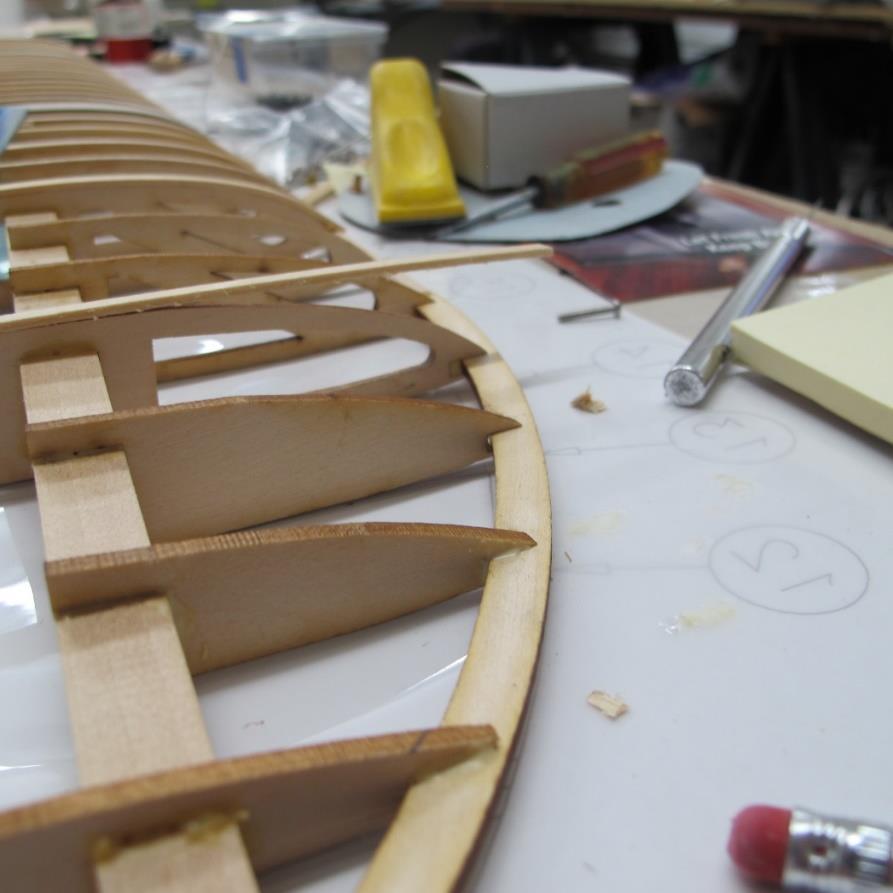
4 Position and glue the nose ribs. Use the leading edge dowel and wood blocks to help secure them in place. Everything should line up well. See photos below


5 Insert the stringers #5.93 into the ribs. They might need a little sanding to fit properly. Wood sometimes expands or is not cut exactly to fit the laser cut holes. You can butt join the stringers. The stringers should go pass the wing tip slightly. See photos below


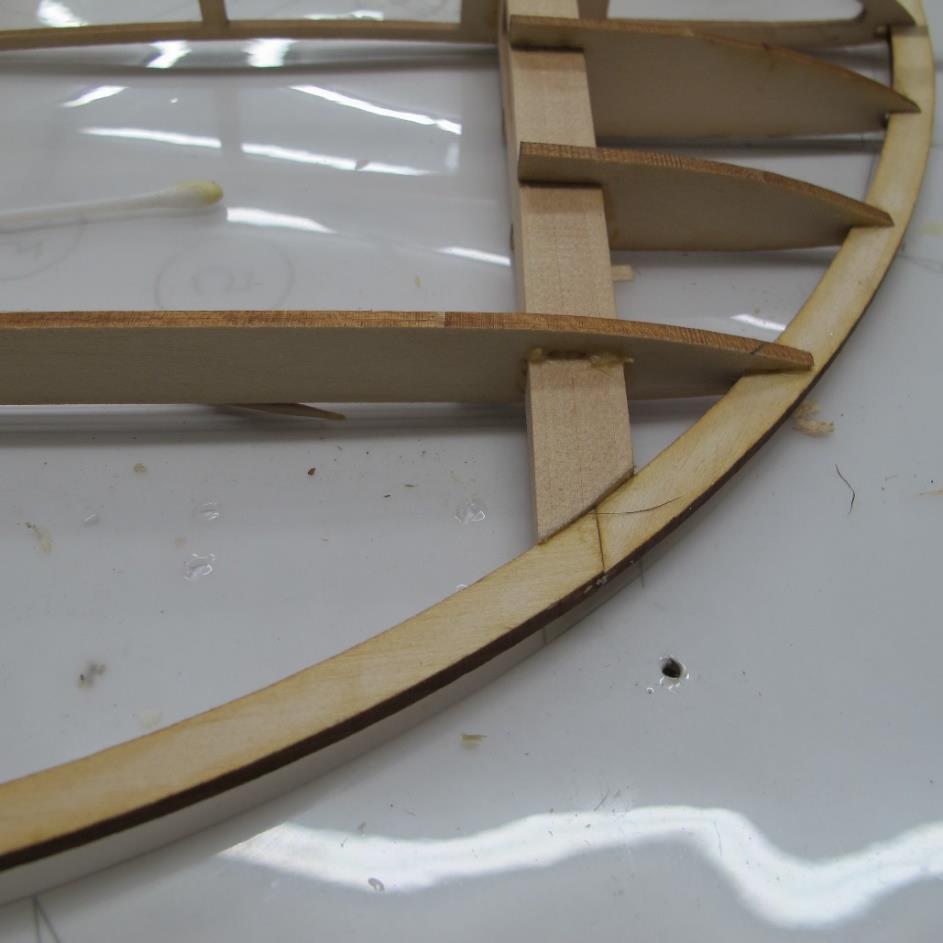
6 Add the trailing edge piece #5.163 now. Note that it will lay flat onto the table and the rib end will go on top. The bottom rib cap will butt join the trailing edge when installed. Use a wood block to secure the rib in place as the wood glue dries. See photo below

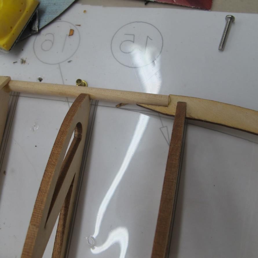
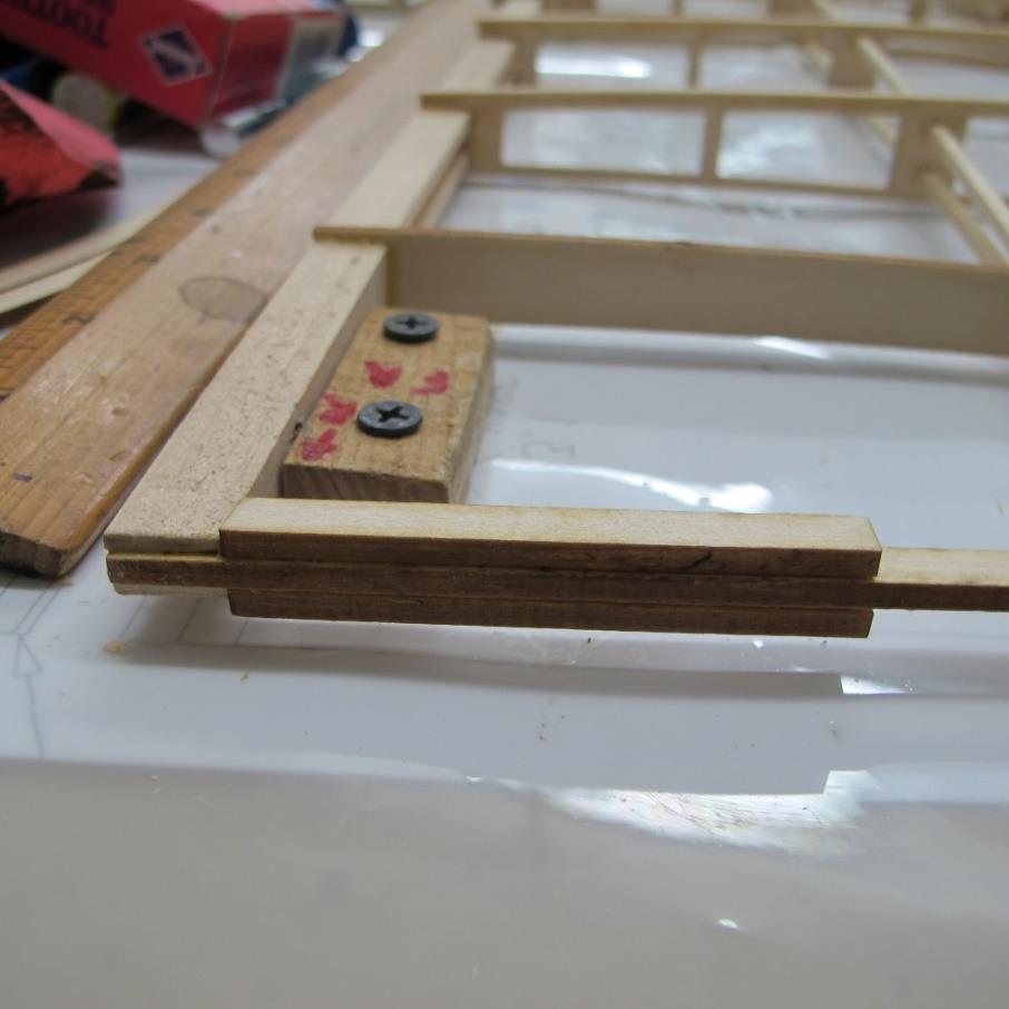
7 To help assemble the wings at the field hard tubes and music wire have been added to the wing design. The hard rod tubes #4.19 and pre-formed music wire #4.20 are the extra pieces used. The music wire is bent at 5 degrees which is the dihedral required when you set your flying wires. The hard rod tubes are predrilled as well. The music wire will also help you align the wings when you assemble the plane. You will notice two holes in the root rib and the two following ribs. Install the hard tubes into these holes making the hard tube end flush with the root rib. The tube will extend past the third rib. Glue these tubes in place. See photos below


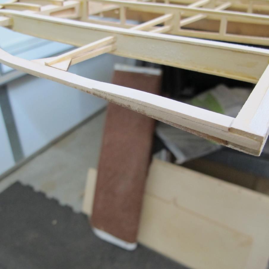
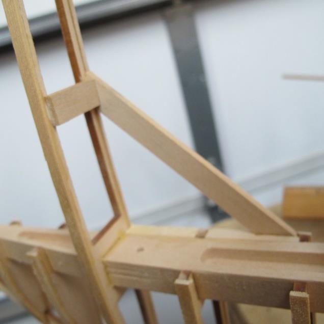
8 The wing tip consists of several wood pieces that are glued into place. Wood parts #5.154 and #5.155 are the main pieces that join the leading edge to the spar. Wood parts #5.156 are supports that go on top and bottom of #5.155 in front of the spar and wood parts #5.157 and #5.158 are glued to the stringers helping them connect to the wing tip. Note that the main piece #5.155 goes into the slot at the end of the spar. Assembly and glue these pieces in place for the wing panel. Once the glue dries sand a taper in # Reference the plans and the photos below
9
10
11


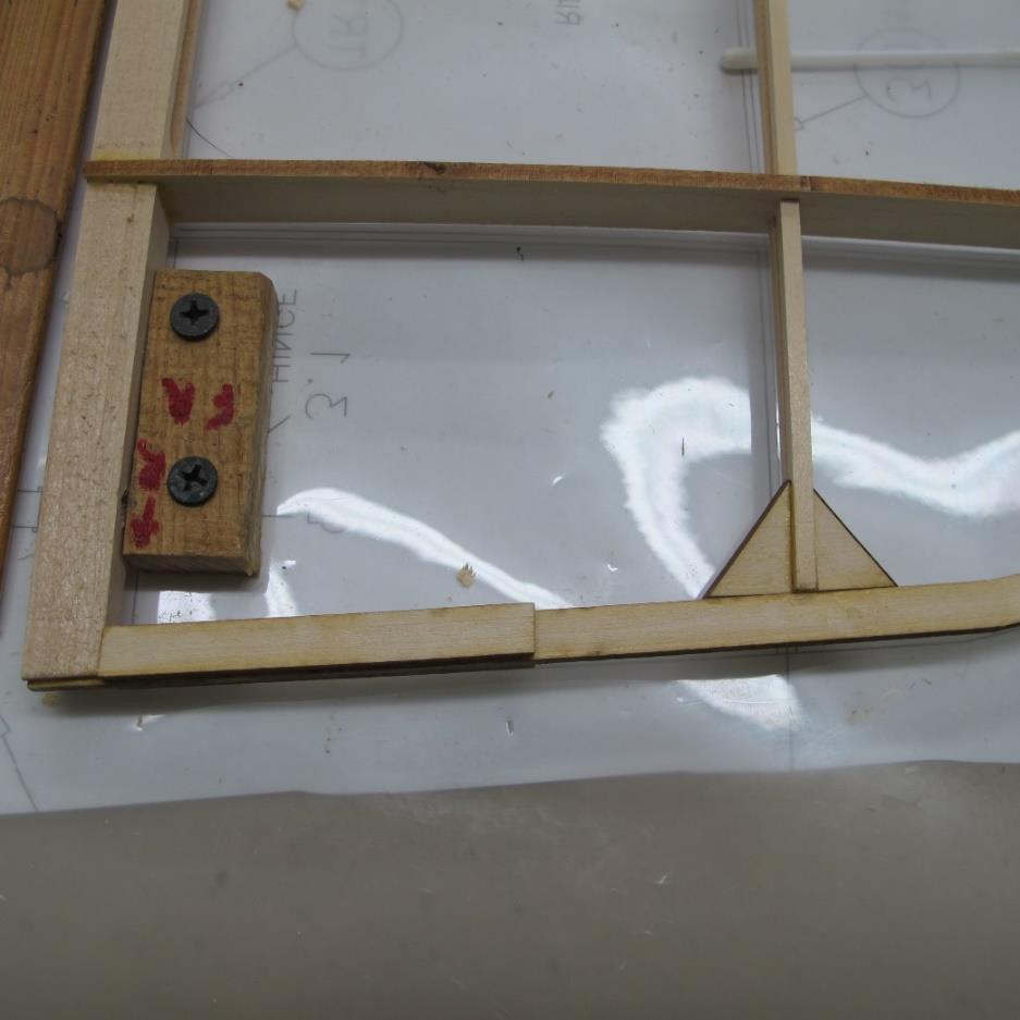
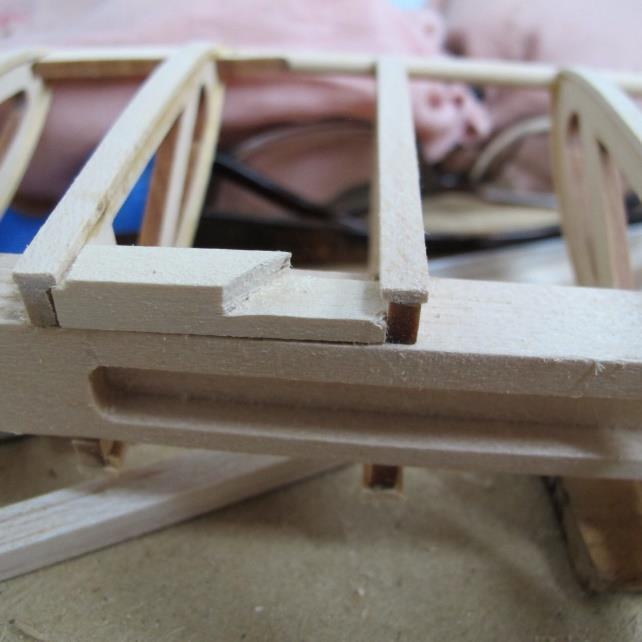
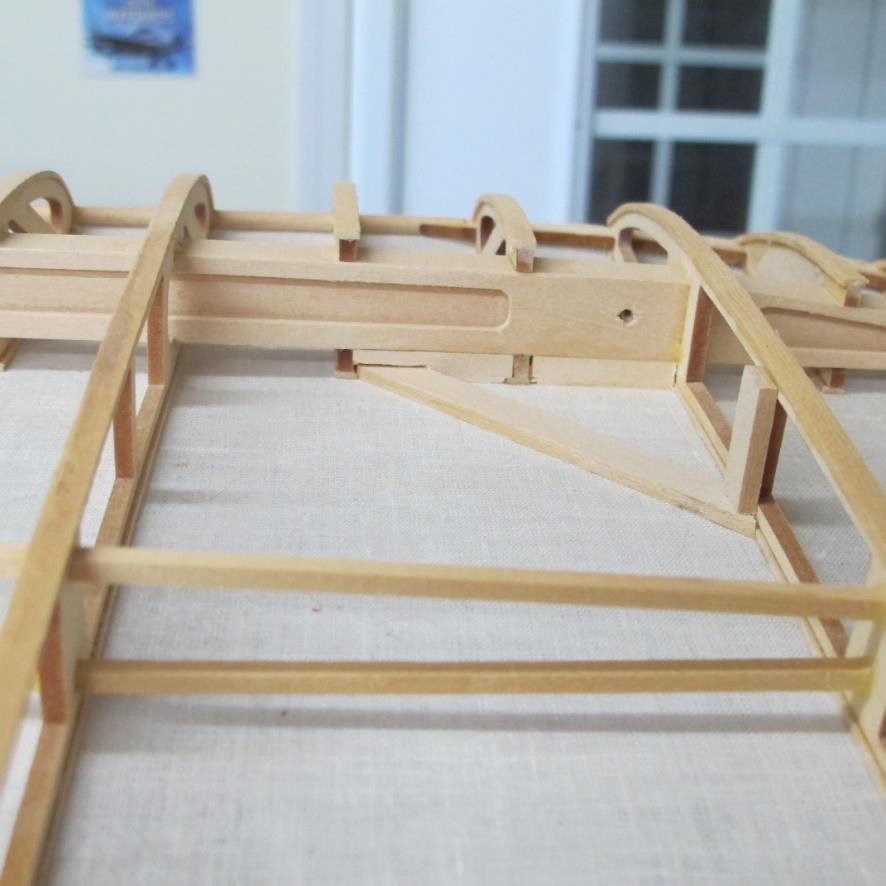
12 Wood blocks #5.105 need to be added for the interplane strut fitting #6.14. See plan sheet 2 side view of the interplane struts. On the bottom wing panel this block would go on top of the spar in-between ribs #5.145 and # On the top wing panel this block would go on the bottom of the spar in-between the same two ribs. At this time cut wood #5.105 to a block that will fit in-between these ribs gluing it into place. Each wing panel gets two blocks; one per spar. Make sure you put them on the right side of the spar. Top wing should have them on the bottom side of the wing and the bottom wing should have them on the top side of the wing. See photo below


13 Each wing panel, top or bottom wing, has three plywood box rib covers. They are at the root ribs, ribs before aileron and the set of ribs sort-of in the middle. The plywood pieces are 5.42 and These covers can be glued in place now. Using clamps and tape secure these covers in place. Reference the plans and see photos below


14 You can add the rib capping now. The goal is to keep the rib capping straight and evenly secured to each rib. It is suggested you start on the wing panel bottom side then do the top side. There is only one rib that has a wider rib cap than the others. This rib #5.148 is the most outer rib which uses a 1/4-inch wide rib cap #5.122 whereas all the other ribs will use the 3/16-inch wide rib cap # You should use the rib capping material wisely as you don t have a lot of scrap. The easiest method to add the rib capping is to put the wing on a 45-degree angle securing it to your building table. You would start at the leading edge working your way to the trailing edge. The rib cap butts up to the trailing edge on the bottom side. On the top side the rib cap goes to the end of the rib over the top of the trailing edge. Use wood blocks down by the leading edge and clamps the remaining way to the trailing edge. You do not need to soak the rib cap wood in water. Remember to keep the rib capping straight removing any extra wood glue. Once done with the bottom side flip wing panel over and do the top side. Do all four wing panels. See photos below


15 There is one aileron hinge per each wing panel (top and bottom) that the interplane bolt #6.14 will go through. This hinge is the most inner one or the 3 rd from the wing tip. It is in the rear spar where you added a wood block. You will need to insert the hinge and then drill thru the block / hinge making room for the interplane bolt. Yes, this is per the original SE5a design but it works well and no need to be alarmed. The side view on plan sheet 3 has a good drawing showing the bolt and hinge on the spar. There is a rather large gap between the wing and ailerons. Again this is the SE5a design which incorporates aileron / wing gap covers, sort-of weird but it s 1918.


16 First, you need to install the hinge #3.1. These are Robart hinges that will fit snuggly into the pre-drilled holes. You can use either Monster glue or Zap hinge glue to secure the hinge in place. Use the glue of your choice and secure the hinge into place. Then using a 1/8 diameter drill bit drill a hole thru the block / spar / hinge centering the hole in the spar. You can then add the blind nut 6.49 into place. The blind nut goes on the bottom side of the bottom wing and the top side of the top wing spar. See photos below The trailing edge in the aileron area will need wood supports in-between the ribs. This filler will support the fabric when it is added. Using #5.182 and #5.183 wood pieces add these supports on the top and bottom side. They should be level with the rib cap height. See photos below


17 Each wing panel has pulley inspection windows. The top wing panels has those windows on the bottom side and the bottom wing panels have them on the top side. Reference the plans for locations. Use wood #5.99 for the cross brace as well as the under support used on the rib. You will have to notch the filler block to allow room for this support. See photos below
18
Note - the nose ribs and are thinner than the main ribs. These nose ribs will use a thinner rib cap than the ribs. This is per design.
 Stabilizer rev 1.2 The SE5a stabilizer is the heartbeat of the tail and is recreated like the full scale version. All tail pieces depend on the stabilizer. It uses the steel fittings, pulleys, inspection
Fokker D8 Master Instructions
 Fokker D8 Master Instructions Rev 1 Congratulations on your new project. The Fokker D8 is a marvellous subject that highlights the success of a monoplane design. The construction of the plane is similar
Continue gluing the remaining top parts ensuring the angled piece is glued well. Set aside and let dry. See photo below
 Radiator rev 1.1 The SE5a s radiator is one of the most recognized radiators in WW1. It is one of the components that defines the SE5a. The original SE5a has seen multiple radiator designs used during
Fokker Dr1 Master Instructions
 Fokker Dr1 Master Instructions Rev 1 Congratulations on your new project. This Dr1 kit is the finest to date. The construction of the plane is similar and exactly like the original. Take your time and
SZD-10 bis CZAPLA ASSEMBLY MANUAL IN PICTURES
 1 RUDDER Plan and parts: 2 Assembly steps: Photo above: glue together rudder spar, ribs and trailing edge. Clamp spar to a flat surface (chipboard on the photo) and make sure the straight aligment of the
SE5a Instrument Board part 2 - rev 1.1
 SE5a Instrument Board part 2 - rev 1.1 Fuel (Petrol) Valve This valve uses two circular name plates, eight brass screws, one black plastic base, copper wire and two black plastic risers. You can pick any
FUSELAGE CONSTRUCTION
 FUSELAGE CONSTRUCTION Note: prior to building and gluing on the work surface use protective covering on your building surface. (wax paper or clear wrap) Fit the laser cut Fuselage Front and Fuselage Rear
90 WING SPAN P-51D MUSTANG (COPYRIGHT PROTECTED 2014) ALL RIGHTS RESERVED
 ALL RIGHTS RESERVED") 90 WING SPAN P-51D MUSTANG (COPYRIGHT PROTECTED 2014) ALL RIGHTS RESERVED GENERAL INSTRUCTIONS This design is basically an enlargement of the very popular fun scale Mustang 60 Size. You can build it light
90 WING SPAN P-51D MUSTANG (COPYRIGHT PROTECTED 2014) ALL RIGHTS RESERVED GENERAL INSTRUCTIONS This design is basically an enlargement of the very popular fun scale Mustang 60 Size. You can build it light
COMET 24" HELLCAT REPRODUCTION ASSEMBLY GUIDE
 COMET 24" HELLCAT REPRODUCTION A RUBBER POWERED 24" WING SPAN MODEL BY PAUL BRADLEY ASSEMBLY GUIDE AUGUST 2016 CHANGES MADE TO THE ORIGINAL The following changes were made to the original Comet kit structural
C-180 Builder s Manual
 C-180 Builder s Manual. May 20, 2002 Last revised July 11, 2002 Copyright! 2002 Douglas Binder, Mountain Models www.mountainmodels.com sales@mountainmodels.com (719) 630-3186 1 Required Equipment! Xacto
Piper Cherokee /3 scale. Construction Manual
 Piper Cherokee 140 1/3 scale Construction Manual STAB CONSTRUCTION 1. Remove foam cores from cradle and place on flat surface. Inspect pieces before you epoxy halves together making sure leading and trailing
The Olympic DLG. (Discus launch glider) by Chris Brislin
 by Chris Brislin") The Olympic DLG (Discus launch glider) by Chris Brislin 1 Contents Parts List/ What you need 3 Before you begin 4 Wing Construction 5-9 Pod Construction 9-13 Tail assembly 13-? Control linkages 9-10 Finishing
The Olympic DLG (Discus launch glider) by Chris Brislin 1 Contents Parts List/ What you need 3 Before you begin 4 Wing Construction 5-9 Pod Construction 9-13 Tail assembly 13-? Control linkages 9-10 Finishing
RESolution V2 Manual
 RESolution V2 Manual Note for the German Manual: Yellow Bottle thick CA Pink Bottle Med CA Blue tube 5 minute Epoxy Green tube 90 Minute Epoxy Construction of the Fuselage Step 1: Cover the plan with a
10. Wing prep and subassembly
 Date Section Objective: Construct and fabricate the sub-assemblies of the wing panel. Required Parts: Wing left 11gal PN104-300, Wing right 1gal PN104-400, Wing left 15 gal option PN104-322, Wing right
Woodline USA Woodline Spacer Fence System
 Woodline USA Woodline Spacer Fence System MADE IN THE USA Includes: (1) ¼ Spacer Fence (1) 3/8 Spacer Fence (1) ½ Spacer Fence (1) Hardware Package (1) 3 Piece Brass bar set (2) Setup Blocks Visit Us Online
Parkflyer F6F Hellcat
 Parkflyer F6F Hellcat Page 1 of 19 MOLT MODELS Background Design Philosophy When I was first introduced to this hobby seventeen years ago I saw my first WWII warbird and I was hooked. Several years later
JAMISON SPECIAL. Building Guide
 JAMISON SPECIAL Building Guide WING Mark then drill holes for wing jig rods. Slide Ribs onto jig rods Mark the rib positions on 1/16 x 1 trailing edge, 1/4 x 1/4 leading edge & 1/4 x 1/4 spars Pin ribs
DRAFT COPY BUILDING INSTRUCTIONS FOR BLACKBURN BUCCANEER S2 VERSION 1 (BETA BUILD) BY MARK DOUGLAS
 BY MARK DOUGLAS") BUILDING INSTRUCTIONS FOR BLACKBURN BUCCANEER S2 VERSION 1 (BETA BUILD) BY MARK DOUGLAS COPYRIGHT MARK DOUGLAS 2011 THIS IS A "SHORT" KIT FOR EXPERIENCED BUILDERS AND FLYERS ONLY, DESIGNED BY A SHED DWELLING
BUILDING INSTRUCTIONS FOR BLACKBURN BUCCANEER S2 VERSION 1 (BETA BUILD) BY MARK DOUGLAS COPYRIGHT MARK DOUGLAS 2011 THIS IS A "SHORT" KIT FOR EXPERIENCED BUILDERS AND FLYERS ONLY, DESIGNED BY A SHED DWELLING
SPUNKY ASSEMBLY MANUAL
 SPUNKY ASSEMBLY MANUAL Please read the tips section at the back of this manual regarding the use of laser cut parts. The proper removal and preparation of these parts is important. When laser cut, some
84 WING SPAN MESSERSCHMITT BF-109
 84 WING SPAN MESSERSCHMITT BF-109 (COPYRIGHT PROTECTED 2014) ALL RIGHTS RESERVED MEISTER 84 ME-109 SIERRA GEAR UPDATE PLEASE NOTE: THE MAIN GEAR MOUNTING PLATE FROM SIERRA IS NOT SQUARE. YOU HAVE TO ROUND
THE APOGEE A 100-INCH AMA DURATION SAILPLANE FROM DYNAFLITE
 THE APOGEE A 100-INCH AMA DURATION SAILPLANE FROM DYNAFLITE Apogee is the intermediate sailplane designed to be competitive in AMA duration contests. Effective spoilers, rudder and full flying stabilizer
Cleveland Quickie Luscombe Silvaire
 Cleveland Quickie Luscombe Silvaire This plan package is not a 100% copy of the original kit. As you make your way through the instructions you will see the differences. Here s just a few of them: The
Hobby Lobby Zip Supplementary instructions Please refer to the included drawings while using these assembly instructions
 Materials needed: 15 or 30 minute epoxy Medium CA Masking tape Scotch tape Servo Tape Wax paper Tools Needed: Pencil or marker Flat building surface Hobby knife or razor blade 7/64" or 3mm drill bit 3/16"
LANDING GEAR. 1. Fit landing gear into slots on bottom of fuselage.
 LANDING GEAR 1. Fit landing gear into slots on bottom of fuselage. 4. Use channel-lock pliers to press blind nuts into position (note: drilled hole should be slightly smaller than shaft of blind nut for
75-TA-4. Elevator Skins
 75-TA-4 This manual has been prepared for assembly of the. This photo assembly manual is intended as a supplement to the drawings. If there is any discrepancy between this manual and the drawings, the
WING ASSEMBLY 23.5 (Continued)
") A VERY IMPORTANT NOTE found on many wing drawings states Do not drill any unspecified holes into spar. This is extremely important as any extra holes may, under extreme conditions, WEAKEN THE SPAR. Note;
A VERY IMPORTANT NOTE found on many wing drawings states Do not drill any unspecified holes into spar. This is extremely important as any extra holes may, under extreme conditions, WEAKEN THE SPAR. Note;
Seascape Bungalow Assembly instructions. Laser Dollhouse Designs
 Seascape Bungalow Assembly instructions Laser Dollhouse Designs NOTE: Please do a dry assembly using only tape to hold house together. This will get you familiar with parts, location, and fit. This also
(Build Instructions)
") (Build Instructions) Specifications * Wingspan: 58cm * Length: 50cm * Flying Weight: 59 grams * Channels: 3 (Rudder Elevator Throttle) * Suggested Receiver: 4Ch Micro * Motor: 8mm GearDrive * Prop: GWS
(Build Instructions) Specifications * Wingspan: 58cm * Length: 50cm * Flying Weight: 59 grams * Channels: 3 (Rudder Elevator Throttle) * Suggested Receiver: 4Ch Micro * Motor: 8mm GearDrive * Prop: GWS
Combat plane for Open B Lanier R/C Inc. P.O. Box 458 Oakwood, GA Phone Fax copyright 2003 Lanier R/C
 Combat plane for Open B Lanier R/C Inc. P.O. Box 458 Oakwood, GA. 30566 Phone 770 532 6401 Fax 770 532 2163 copyright 2003 Lanier R/C Important information: Please inspect the plane before beginning to
Build the Spitfire: Step-By-step. Pack 3 Stages 21-30
 Pack Stages 2-0 Contents Stage Page Number 2 72-74 22 75-78 2 79-8 24 82-84 25 85-88 26 89-9 27 92-94 28 95-97 29 98-00 0 0-05 Editorial and design by Continuo Creative, 9-4 North Road, London N7 9DP All
96 WING SPAN SPITFIRE (COPYRIGHT PROTECTED 2014) ALL RIGHTS RESERVED
 ALL RIGHTS RESERVED") 96 WING SPAN SPITFIRE (COPYRIGHT PROTECTED 2014) ALL RIGHTS RESERVED GENERAL INSTRUCTIONS Should you elect to use the recommended Door Skin, which is 1/8 mahogany plywood measuring 36 x 88. Have it cut
96 WING SPAN SPITFIRE (COPYRIGHT PROTECTED 2014) ALL RIGHTS RESERVED GENERAL INSTRUCTIONS Should you elect to use the recommended Door Skin, which is 1/8 mahogany plywood measuring 36 x 88. Have it cut
Why are we giving this guidebook as a FREE download?
 Construction Guide Queen, Double & Twin Vertical 1 Note: This guide covers the construction steps for all 3 sizes of the vertical wall mount Easy DIY Murphy beds, Queen, Double and Twin. The construction
Building Tips This model can be built using the following types of adhesives:
 Page 1 Building Tips This model can be built using the following types of adhesives: Epoxy (with or without microballons) Odorless cyanoacrylate (CA) with accelerator UHU Creativ for Styrofoam (or UHU
1/16" Square balsa strip stock is used for the fuselage and tail surfaces structure. 10T 11T 11B (2) 10B. Pec Bea. Wingspan - 18"
 10B. Pec Bea. Wingspan - 18") 1/16" Square balsa strip stock is used for the fuselage and tail surfaces structure. 10T 9T 8 11T 12 7T 6T F-1 7 11 (2) 10 9 6 13 Pec ea CAD Drawing by Paul radley Sheet 1 of 8 Nose plug is a lamination
1/16" Square balsa strip stock is used for the fuselage and tail surfaces structure. 10T 9T 8 11T 12 7T 6T F-1 7 11 (2) 10 9 6 13 Pec ea CAD Drawing by Paul radley Sheet 1 of 8 Nose plug is a lamination
STOL CH 701. Standard L ANGLES are supplied in 4ft length. Ref. bottom left diagram on drawing 7-V-2
 Standard L ANGLES are supplied in 4ft length. Ref. bottom left diagram on drawing 7-V-2 Length = 206mm. Layout the cut line on the outside flanges. Ref. see boxed diagram on drawing 7-V-2 Three vertical
Fibertech N More cc 103 SUPER CHIPMUNK ASSEMBLY MANUAL. pg. 1
 Fibertech N More 50-60cc 103 SUPER CHIPMUNK ASSEMBLY MANUAL pg. 1 Introduction Thank you for choosing Fibertech N More 103 Super Chipmunk. We have taken great effort into making this kit a great plane
Stearman PT-17 KIT WARRANTY
 Stearman PT-17 KIT # K-306 Assembly Instructions Version 2 02-17-16 Designed by Tom Herr WARRANTY Sig Manufacturing Co, Inc. guarantees this kit to be free from defects in both material and workmanship
RSM DISTRIBUTION Presents
 RSM DISTRIBUTION Presents MOSQUITO By Jack Sheeks Photo _ Jack Sheeks Semi Scale Twin Stunter Wing Span: 58" Length: 37-3/4 Area: 579 sq. in. Engine: Two.35 -.40 www.rsmdistribution.com Call (951) 678
Drilling Your Wings to Your Fuselage
 Drilling Your Wings to Your Fuselage The purpose of this write up is to give some further guidance on how to get the best results drilling your wing spar attach holes to the upper fuselage attach fittings.
Important Note: Why this guidebook is FREE?
 Easy DIY Murphy Bed Construction Guide 1 Important Note: This guide is a FREE SAMPLE of our Complete Construction Guidebook. With the help of this guide you will get familiar with the construction steps
3 rd scale SE5a Biplane kit
 3 rd scale SE5a Biplane kit This SE5a kit represents years of research and development. The kit was designed around original RAF factory drawings loaned by WW1 Aero. Original construction and materials
77.5 degrees REAR CHANNEL PLYWOOD TEMPLATE
 77.5 degrees REAR CHANNEL PLYWOOD TEMPLATE Ref. 6-B-14 Make following template: Vertical distance = 300mm Layout dimensions shown in the bottom right table on drawing 6-B-14 Top and bottom are square to
High performance 90mm fiberglass jet
 High performance 90mm fiberglass jet Assembly manual For intermediate and advanced fliers only! Specs Wingspan: 1255mm Fuselage length: 1250mm Flying weight: 2600-3000g Wing area: 22.6 dm² Wing loading:
Dandy Sport Builder s Manual
 Dandy Sport Builder s Manual Thank you for purchasing the Dandy Sport. The Dandy Sport has been designed as an easy to build aileron trainer. Take your time and enjoy building this plane. Specifications:
Section C75-WA-1. Wing Skeleton
 Section C75-WA-1 This manual has been prepared for assembly of the wing skeleton supplied with match drilled parts. This photo assembly manual is intended as a supplement to the drawings. If there is any
11) Chromate the mating surfaces of the Leading edge Root Rib, Doubler and Root Rib Stiffeners. Rivet together with 1/8 rivets (RV-1410).
 Chromate the mating surfaces of the Leading edge Root Rib, Doubler and Root Rib Stiffeners. Rivet together with 1/8 rivets (RV-1410).") 11) Chromate the mating surfaces of the Leading edge Root Rib, Doubler and Root Rib Stiffeners. Rivet together with 1/8 rivets (RV-1410). 12) Chromate the Root Rib Attach Bracket and rivet to the Root
11) Chromate the mating surfaces of the Leading edge Root Rib, Doubler and Root Rib Stiffeners. Rivet together with 1/8 rivets (RV-1410). 12) Chromate the Root Rib Attach Bracket and rivet to the Root
A Flying Grumman Fighter How You Can Build a Model of One of the Latest U.S. Navy Fighters That Is an Excellent Flier By WILLIAM WINTER
 A Flying Grumman Fighter How You Can Build a Model of One of the Latest U.S. Navy Fighters That Is an Excellent Flier By WILLIAM WINTER The completed model is faithful to scale and detail THE Grumman F3F-1
2.1 Parts List Tool requirement Before you start assembling the Stabiliser Front Spar Center Doublers...
 Stabilizer Assembly 2.0 Exploded View...Error! Bookmark not defined. 2.1 Parts List...3 2.2 Tool requirement...5 2.3 Before you start assembling the Stabiliser...6 2.4 Front Spar...6 2.5 Center Doublers...7
BUILDING INSTRUCTIONS FOR FINEWORX. Miles. 2M Class Competition Glider. Congratulations! You have purchased our Miles, 2M Class Competition Glider.
 BUILDING INSTRUCTIONS FOR FINEWORX Miles 2M Class Competition Glider Congratulations! You have purchased our Miles, 2M Class Competition Glider. The Miles is the first offering from FINEWORX, a new company
Chap. 9.2 SR3500 Fuselage Assembly - Cabin. MODEL: SR Murphy Aircraft Mfg. Ltd. All rights reserved.
 26/06/2006 Page 1 26/06/2006 Page 2 26/06/2006 Page 3 Parts List for Gear Box No. Part Number Description Qty Required 1,23 FUS0711QL BRACING CHANNEL 2 2,22 FUS0711QR BRACING CHANNEL 2 3 FUS301QB CARRYTHROUGH
INCLUDED IN THIS KIT: SPECIFICATION: NEEDED BUILDING TOOLS: REQUIRED EQUIPMENT:
 Please review this entire manual before beginning assembly. By doing so it will help you better understand each step as you progress in the actual building of your kit, and you will do a better job in
Citabria Pro. Aerobatic Parkflyer. by Joel Dirnberger
 Citabria Pro Aerobatic Parkflyer by Joel Dirnberger Revision C: December 21, 2004 Citabria Pro Building Instructions Length: Wingspan: Wing Area: Flying Weight: Wing Loading: Functions: Specifications:
LANIER Dominator INSTRUCTIONS
 ADDITIONAL EQUIPMENT NEEDED TO COMPLETE YOUR DOMINATOR 500 General 3.2 to 4.2 Size two stroke R/C engine, muffler, and engine mount Gas or glow fuel line Minimum of 4 channel radio set required (4-5) 70
Bates 1/8 scale B-26. Parts List. Instructions
 Bates 1/8 scale B-26 Vacuform Pieces Swivel Ball 1 Cockpit Floor 1 Ball 2 Cockpit Back Wall 2 Two Flanges 3 Dash 3 Seven 0-64 x 1/4 Bolts 4 Dash Hood 4 Seven 0-64 Nuts 5 Center Console 6 Pilot Seat Fire
ParkJet Builder s Manual
 ParkJet Builder s Manual Thank you for purchasing the ParkJet. The ParkJet is a profile ducted fan airplane that can be flown in a larger park. The ParkJet was initially designed by Scott Stoops and modified
Designed in 2005 by Bernard Burton. Assembly manual Bernard Burton DRAFT 1
 Designed in 2005 by Bernard Burton Assembly manual 2005 - Bernard Burton DRAFT 1 The plans can be requested via this link http://www.gundersonaerodesign.com/m12plansreq.htm The laser kit is available here
1/6 PA-25 PAWNEE. *Specifications are subject to change without notice.*
 1/6 PA-25 PAWNEE INSTRUCTION MANUAL [ A335 Kit ] Wing Span : 72 in / 1830 mm Wing Area : 736 sq in / 47.5 sq dm Flying Weight : 6.6 lbs / 3000 g Fuselage Length : 48 in / 1220 mm Requires : "Glow Power"
LANIER - Ultimate Pitts - INSTRUCTIONS. Additional Parts Required. (12) 4-40 blind nuts (Dubro #606)
 4-40 blind nuts (Dubro #606)") Additional Parts Required (4) or more channel radio with 7-8 servos..91-2.2 two stroke or 1.20-1.84 four stroke engine Appropriate Master Airscrew prop and Hayes mount for your engine. 3 Tru-Turn spinner
Additional Parts Required (4) or more channel radio with 7-8 servos..91-2.2 two stroke or 1.20-1.84 four stroke engine Appropriate Master Airscrew prop and Hayes mount for your engine. 3 Tru-Turn spinner
The Castle House Assembly Instructions By Laser Dollhouse Designs
 The Castle House Assembly Instructions By Laser Dollhouse Designs HOUSE PARTS First floor slots labeled 1A-1G First floor Walls labeled 1A-1G First floor interior door frames (4) Wall 1A frames (6) Main
Building Instructions P-51 BF109
 Building Instructions P-51 BF109 Sport model for.015 engines. Legal for SSC Warbird Lanier R/C Inc. P. O. Box 458 Oakwood, Ga. 30566 Copyright 2004 Lanier R/C Inc. Important information: Please inspect
STOL CH 701. Clamp a reference extrusion on the bottom of the spar. Clamp the bottom flange of the rib to the extrusion. Rear Root Rib 7V4-2
 Rear Root Rib 7V4-2 Clamp a reference extrusion on the bottom of the spar. Clamp the bottom flange of the rib to the extrusion. Cleco the root nose rib to the spar Position the rear root rib at station
6mmFlyRC.com Super Bandit Assembly Instructions
 Assembly Instructions Start the assembly with forward fuselage. Lay the two fuselage sides down on a flat surface and glue the foam corner doublers to the locations shown on the plans. Make sure to make
Chapter 2. Section 3- Ailerons
 Chapter 2 Section 3- Ailerons Material: Hangar 9 servo arms - 8 4-40 x ¼ button head screws - 16 Dubro ¼ scale hinges - 2 pckgs The ailerons are built using 3/32 x 4 x48 balsa sheet. Cut the sheets to
Switchback Sport Builder s Manual
 Switchback Sport Builder s Manual Thank you for purchasing the Switchback Sport. The Switchback Sport has been designed for the novice to intermediate pilot who wants a plane with good performance that
Easy Built Models Kit JX-02 MiG-15 Conversion to Rubber-Power By Matt Payne, October 2011
 Easy Built Models Kit JX-02 MiG-15 Conversion to Rubber-Power By Matt Payne, October 2011 The fuselage is restructured. The Jetex-related structural components, the stock keel parts, and the formers are
PITTS S2S CONSTRUCTION
 PITTS S2S CONSTRUCTION FUSELAGE CONSTRUCTION 1) Place the right fuselage side over the plan and mark the former positions. Place the left side over the right side and mark the former positions. Glue F1
A large prop insures high performance. Cleverly designed to give a realistic appearance
 Cleverly designed to give a realistic appearance A large prop insures high performance A Vought Fighter That Flies Complete Data from Which You Can Build an Excellent Performing Flying Scale Model of the
Building a Giant Scale Electric EINDECKER Part 2
 Building a Giant Scale Electric EINDECKER Part 2 John Bernard N1KUB AMA 58903 IMAA 28971 In Part-1 of this series, we explored the 100 Eindecker kit from SR Batteries and started building the fuselage.
Package contains. Required tools and consumables:
 Thank you for purchasing the TriTrix MTM Transmission Line cabinet kit. This cabinet kit was precision cut using CNC machinery for the best possible fit and finish. With a little time and patience, your
12. Wings, Flaps, Ailerons and Struts
 12. Wings, Flaps, Ailerons and Struts Fit Aileron Hinges Reference: Drawing 20270K2 Photo 12.1 Parts Required: 2007092 Aileron LS 200809N Aileron RS 2001394 Hinge 3/16 A1 (4) 2001694 Hinge Pin (4) PH0059N
Falke Build Instructions
 A totally unofficial translation of the Falke Build Instructions The Falke (falcon) mini DLG is produced and marketed by Modellbau Thiele, Germany (www.modellbau-thiele.de), email webmaster@modellbau-thiele.de.
Introducing The Cloud Models Westland Whirlwind
 Produced by Cloud Models,Deopham Road,Morley,Wymondham, Norfolk,NR18 9AA E-mail sales@cloudmodels.com web site cloudmodels.com Introducing The Cloud Models Westland Whirlwind By Tricks Thank you for purchasing
Corvus Racer Colour schemes. AeroPlus RC Copyright 2013 All Rights Reserved
 Corvus Racer 540 59 Item No:A E050003 Specifications WING SPAN: 59"(1500mm) LENGTH: 54.1"(1374mm) WING AREA: 654sq.in.(42.2sq.dm.) FLYING WEIGHT: 4.6 5.3lbs(2000 2300g) Electric:Brushless outrunner 8Oz.
Entrance Cabinet Plans
 Entrance Cabinet Plans www.andrewharriswoodwork.com Page 1 of 19 Introduction I have tried to ensure all steps are covered in these plans but if you find any errors in the plans or have a question then
Grade 11 Woods Lift Lid Coffee Table. Based on Under the big Top from Popular Mechanics Website
 Grade 11 Woods Lift Lid Coffee Table Based on Under the big Top from Popular Mechanics Website TABLE TOP 1. Select enough lumber to construct a top that is between 22 ½ and 24 wide after jointing. Ensure
4. Bevel the LE face of HS1-HS11 to match the horizontal stab leading edge sweep angle.
 BEFORE YOU BUILD 1. Unroll each sheet of the plans. Roll them inside out so that they will lie flat on the building surface. 2. Assemble the tools that you will need to build each section so that they
SE5A - MAIN PARTS AND FRAMES BUILDING SCHEDULE
 SE5A - MAIN PARTS AND FRAMES BUILDING SCHEDULE THE FUSELAGE At this point the major side pieces of the fuselage should be very carefully handled as before the various stiffeners and other structural parts
WRIGHT FLYER 1 INSTRUCTIONS FOR THE D10LC KIT
 WRIGHT FLYER 1 INSTRUCTIONS FOR THE D10LC KIT Manufactured in the USA by Easy Built Models PO Box 681744, Prattville, AL 36068-1744 Visit us at www.easybuiltmodels.com Easy Built Models GLUE METHODS Always
SPAD. SPAD Derelict. Simple Plastic Airplane Design
 Derelict SPAD Simple Plastic Airplane Design SPAD Derelict The Derelict. This is our third design entry for an RCCA legal open "B" class plane. The main difference in this design is the choice of materials.
FireFighter.21 Building Instructions
 A Tom Moorehouse design. Thank-you for purchasing the FireFighter.21. I believe that you will find it to be the best.21 rigger kit available. It has won 1 st place in the 2006 AMPBA nationals! It was designed
HIGH-END TECHNOLOGY. Electric ducted fan rafale
 HIGH-END TECHNOLOGY RC Electric ducted fan rafale First we want to thank and congratulate you with your decision in buying one of our Kits. The Rafale puts together very easily so there is not much explanation
Three vertical L angles must be riveted to each main spar (length = 206mm see boxed diagram on drawing 7-V-2).
.") Cut over-sized (left); Trim and file (above). Note: Six needed. Three vertical L angles must be riveted to each main spar (length = 206mm see boxed diagram on drawing 7-V-2). Trace line down center of
Cut over-sized (left); Trim and file (above). Note: Six needed. Three vertical L angles must be riveted to each main spar (length = 206mm see boxed diagram on drawing 7-V-2). Trace line down center of
FLITZEBOGEN-2 Assembly instructions
 FLITZEBOGEN-2 Assembly instructions Trim the end of the fuselage to the length of 925mm from the nose. Be careful to avoid splitting the carbon fibers. Sand the base of the stab mount in preparation for
PT Military Trainer. R/C Scale Model Instructions CONTACT INFORMATION
 PT Military Trainer R/C Scale Model Instructions CONTACT INFORMATION The PT Military Trainer was designed by: M.K. Bengtson Prototype by: Brian Allen Manufactured and Distributed by: Bengtson Company e
S.E.5a (Build Instructions)
") S.E.5a (Build Instructions) Specifications Wingspan: 38 cm Length: 31cm Flying Weight: 41 Channels: 3 (Rudder Elevator Throttle) Suggested Receiver: 3Ch Brick Motor: 7mm Geared Motor Airframe Only Kit
S.E.5a (Build Instructions) Specifications Wingspan: 38 cm Length: 31cm Flying Weight: 41 Channels: 3 (Rudder Elevator Throttle) Suggested Receiver: 3Ch Brick Motor: 7mm Geared Motor Airframe Only Kit
Bantamtm Instruction Manual 2002
 Bantamtm Instruction Manual 2002 These instructions cover the construction of both the Bantam and the Bantam Bipe. Both aircraft are Slow Flyer/Indoor Flyer aircraft designed for calm winds outdoor flying
Installation Instructions Universal Crossmember Kit - 60 Track Width BEFORE Measure Twice, Weld Once! II
 Installation Instructions Universal Crossmember Kit - 60 Track Width Please read these instructions completely BEFORE starting your installation. Remember the basic rule for a successful installation:
F100 Super Sabre instructions.
 F100 Super Sabre instructions. The F100 is a Jet model for the Wemotec 480 Minifan. Start with taking the parts out of the sheet and sand of the connection tabs. Instructions RBCkits F100 Super Sabre 1
SASKATOON, Saskatchewan
 CONSTRUCTION GUIDE AVRO ARROW (CONTEST VERSION) Copyright, Bill Jones, 2004 SASKATOON, Saskatchewan This is a work in progress, so there are a couple of rough areas ( I ll point out those that I m aware
84 WING SPAN MESSERSCHMITT BF WIN G S P A N
 84 WING SPAN MESSERSCHMITT BF-109 10 2 WIN G S P A N MESSERSCHMITT BF-109 THIS IS A VERY EASY PLANE TO BUILD BEFORE YOU START The fuselage self jigging system used an easy accurate assembly. But, attention
Contents. Build the Spitfire: Step-By-step
 Pack 2 Stages -20 Contents Stage Page Number 8-0 2 - - 7 8-50 5 5-5 6 5-57 7 58-60 8 6-6 9 6-67 20 68-7 Editorial and design by Continuo Creative, 9- North Road, London N7 9DP All rights reserved 20 De
100 WING SPAN MESSERSCHMITT BF-109 (COPYRIGHT PROTECTED 2014) ALL RIGHTS RESERVED
 ALL RIGHTS RESERVED") 100 WING SPAN MESSERSCHMITT BF-109 (COPYRIGHT PROTECTED 2014) ALL RIGHTS RESERVED BEFORE YOU START The fuselage self jigging system used an easy accurate assembly. But, attention to detail when cutting
100 WING SPAN MESSERSCHMITT BF-109 (COPYRIGHT PROTECTED 2014) ALL RIGHTS RESERVED BEFORE YOU START The fuselage self jigging system used an easy accurate assembly. But, attention to detail when cutting
Obtained from Omarshauntedtrail.com
 DaveintheGrave's Halloween Props Animated Crawling Skeleton Build a life-size skeleton torso that realistically crawls across the lawn one arm at a time. 1. Motor Base and Linkage Assembly BASE - I used
Scratchbuild A Backwoods Water Tank Part V - Making the Frost Box and Hanging the Water Spout
 Scratchbuild A Backwoods Water Tank Part V - Making the Frost Box and Hanging the Water Spout By Dwight Ennis In this section, we're going to make the Frost Box, and we'll build the Spout Hanger Assembly
A Class A Gas Model That Looks Like a Full Scale Plane and Performs Like a Contest Ship
 A Class A Gas Model That Looks Like a Full Scale Plane and Performs Like a Contest Ship By SAL TAIBI 1941 NATIONAL WINNER The little plane glides in with all the realism of a full scale craft The plans
MECOA EZ-4061 Trainer
 MECOA EZ-4061 Trainer EZ-4061 is a newly designed, Almost Ready to Fly kit. It is an extremely easy to control trainer with strong construction and excellent aerodynamic performance. This is a great choice
Plastic Trainer-19. I have tried to only use materials available from the big box building centers like Home Depot, Rona (Canada) and Lowe s.
 and Lowe s.") Plastic Trainer-19 I have tried to only use materials available from the big box building centers like Home Depot, Rona (Canada) and Lowe s. The picture above shows the prototypes with an original Cox
Plastic Trainer-19 I have tried to only use materials available from the big box building centers like Home Depot, Rona (Canada) and Lowe s. The picture above shows the prototypes with an original Cox
NASTY Build Guide. Supplies needed
 NASTY Build Guide Supplies needed Blucore or Depron Foam. Blucore (Fan Fold Foam) is available at Lowes. Approximately $25 for 50 feet of Blucore. Depron can be ordered on the internet for slightly more.
9.3 FUSELAGE ASSEMBLY 14/03/02
 9.3 MATING THE TAIL CONE TO THE CABIN 1) Trim the bottom flange of both FUS-339 side skins on the tailcone assembly as in Figure 1. 2) Remove the bottom two RBULK 2A s of bulkhead A on the tailcone. 3)
Corvus Racer CC
 Corvus Racer 540 35CC Item No:L-G035008 Specifications Wing Span Length Wing Area Flying Weight Glow Gasoline Electric Radio mm mm 1200sq in (77.4sqdm) 9.9-12lbs(4.5-5.5kg) 91-1.20(2C) 1.10-1.40(4C) 20-40cc