Continue gluing the remaining top parts ensuring the angled piece is glued well. Set aside and let dry. See photo below
|
|
|
- Joel Moore
- 6 years ago
- Views:
Transcription

1 Radiator rev 1.1 The SE5a s radiator is one of the most recognized radiators in WW1. It is one of the components that defines the SE5a. The original SE5a has seen multiple radiator designs used during manufacturing. The kit includes the later version which has the two banks of shutters on each side of the propeller. The radiator has a lot of different parts that work together and must be assembled properly. Take some time to inspect the parts and understand how everything goes together. The assembled radiator with shields, shutters, etc. will be painted as one unit. The honeycomb material will not be painted. The radiator can be removed from the plane like the original. Note about your engine selection. The prototype used the DA-85 engine (shown on plans) with a prop 1-1/4-inch extension and custom muffler, see plans for further details. This engine solution worked well as it eliminated any radiator modifications. Other engines will work, although I have not explored all solutions. Just note that you might have to do some minor radiator modifications as there are two main issues you should be concerned about when selecting an engine; the radiator thickness and prop shaft location. You need to decide on where your prop shaft will exit the radiator and your engine orientation. Just remember other parts of the plane connect with the radiator so don't get too happy with modifications. Don t forget that the dummy engine block starts about 3/4-inch behind the radiator and the upper engine metal hoods secure to the radiator top as well. You will start with the radiator wood frame first. It is important that the frame be built straight with no warps. The honeycomb, shutters, music wire, etc. need to fit rather perfect. Just take your time and understand what you are doing. Having the fuselage built up will help you check the radiator fit as well. Plan sheet one shows the front view of the wooden frame. Gather all the wood parts shown in the front view. Lay them in position over front view radiator plans. Understand their correct orientation and position. See photo below


2 Assemble these parts together without gluing. They should sort-of snap together. Parts #5.5 and #5.10 have a laser etched arrow which indicates the front. Ensure the arrow is pointing towards the propeller. The four vertical pieces # have three holes for each G10 clip #1.3. These holes should be closest to the propeller or the front of the radiator. Ensure you have everything oriented correctly. Disassemble the parts. Using a wood glue start gluing these parts together. Start at the bottom working your way toward the top. Try using some support blocks holding the parts in position. Don't get too happy with glue. Keep glue out of rivet holes and the two inner slots for parts 1.2. See photo below
 Note these blocks are wider than the wood frame by design.")
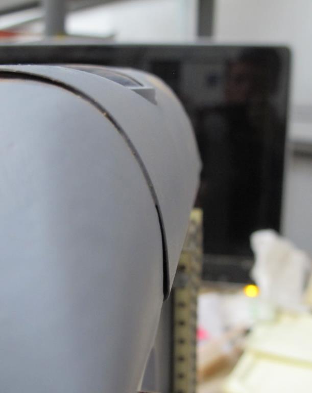
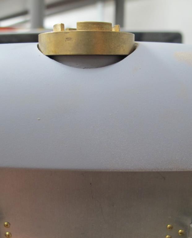
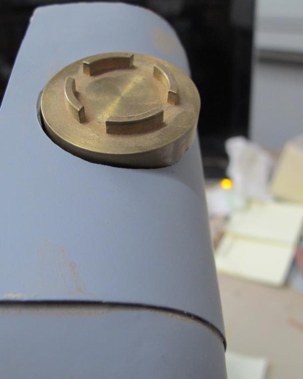
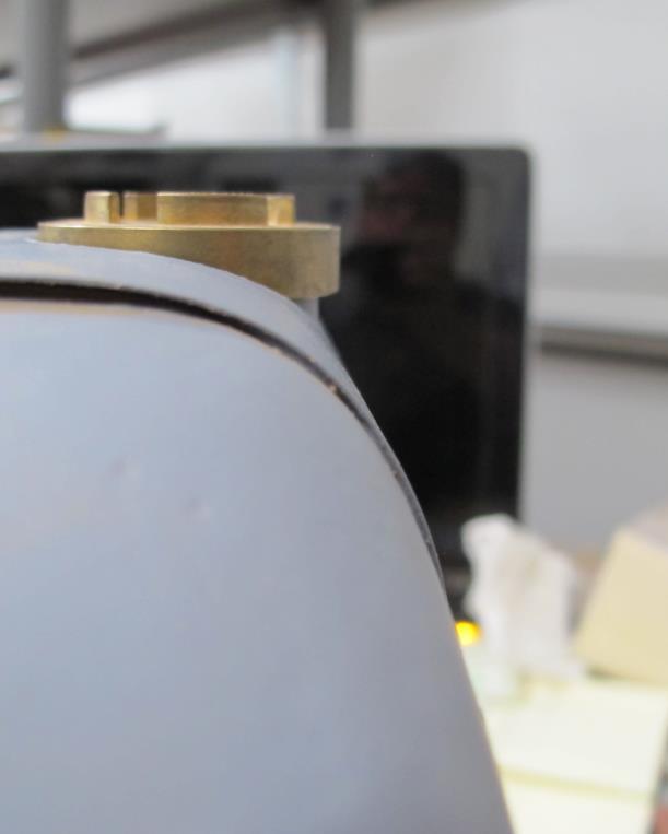
3 Continue gluing the remaining top parts ensuring the angled piece is glued well. Set aside and let dry. See photo below Three balsa blocks #5.225 and #5.226 are used to simulate the header tanks. (I forgot to take photos of them being installed and sanded. Although, the photos below will help you with this area.) Note these blocks are wider than the wood frame by design. They need to be flushed with the top plywood piece #5.5 leading edge. The rear of these blocks will extend pass the top plywood piece #5.5 but that is by design as the rear will support the upper metal engine hoods, hinge and cable. The center block will be covered with a metal sheet #4.6 the two outer balsa blocks #5.225 will not be covered with metal. The center block has a 1-inch diameter dowel #5.15 used in it to locate the correct height of the brass radiator cap #4.39. The top plywood frame piece #5.5 locates that dowel. Set the center balsa block #5.226 in position on the wooden frame having it flush with the leading edge of plywood #5.5. Use a pencil and mark the location of the dowel on the bottom of this balsa block. Remove the block. Using a 1-inch diameter drill bit, drill a hole for the dowel all the way thru the balsa block. The radiator cap is wider than 1-inch. You need to use a 1-1/2-inch drill bit such as a Fostner bit, drilling down a 5/8-inch centered into this 1-inch hole. That would give a slight clearance for the radiator cap to sit on the dowel correctly. Drill this wider hole now. Glue the center balsa block to the wooden frame now. Carefully, sand the front curve into this balsa block. Do not sand the rear, leave as is. Reference the plans. Once satisfied with the sanding insert and glue the dowel in place. Remember to keep the dowel flush with the bottom of the top plywood piece #5.5. Test fit the radiator cap #4.39. It should look like the photos below. Make any adjustments as needed. Remove the radiator cap for now. You can permanently glue in place after radiator is painted. When the radiator is finished some of the dowel under the radiator cap should be visible. Glue the two outer balsa blocks in place now. Carefully, sand them to shape matching the plans. These blocks are


4 slightly lower than the center block. See plans. Also, these outer blocks should slope down to the outside and curve towards the front matching the front curve in the center block. See photos below
5


6 Trim the metal cover to shape. Use a Foster drill bit 1-1/2 diameter to cut the center hole for the radiator cap. This is easily done by drilling in some scrap wood first then lay metal over that wood and drill thru the metal into the wood hole. Bend the front edge 3/8 inch. Use epoxy to hold the front edge in place then wrap the metal around gluing it into position. This would be a good time to sand and seal this wood frame getting it ready to paint. Use a wood primer to do that getting the finish you desire. Remember this wood frame should look like metal as the original was metal. The prototype used Plastikote sandable primer grey color. This color helps highlight any imperfections. Locate parts #1.1 thru 1.4. These G10 parts are messy as all G10 parts are. You need to lightly sand the edges and the outside. Ensure you understand where these parts go on the radiator frame. Parts 1.1 and 1.2 are not equal. Part 1.2 has a slot on the bottom which this part goes on the inside of the radiator. See plans. Test fit these parts now using the aluminum rivets 6.1. Ensure the rivet head seats all the way down onto the G10 fitting. After you have these parts in position use some thin CA glue to


7 secure the rivets and G10 parts to the wooden radiator frame. Don't get happy with the glue just ensure they won't vibrate loose. You can use the aluminum tube #4.3 to align the four radiator mount brackets. Aluminum tube #4.3 can be trimmed to length. This tube secures the radiator bottom in place. See photos below


8 You can test fit the wooden frame in place onto the fuselage ensuring the mount brackets align to the radiator bracket #1.6 on the bottom fuselage longeron. The aluminum tube #4.3 should extend about an 1/8-inch past the G10 mounting brackets. The mounting brackets should be on the outside of the radiator bracket. See photo below The two aluminum honeycomb grills #4.1 are cut a wee-bit larger than needed. They should fit in your wooden frame snuggly. They should not alter your wooden frame. The shutters and shutter frame will cover some slight mistakes but at this time cut the honeycomb grill to size test fitting into place. You can use some tape to help you cut the honeycomb straight. Using a metal bandsaw will cut the material. Take your time. Make a right and left version. The honeycomb grill should be flush with the front of the wooden frame. See photos below The two center metal shields #4.7, 4.8 are held in place with aluminum clips #4.43 that are epoxied in place using brass nails #6.59. Remove these pieces from the aluminum sheet removing any burrs. These shields are very visible. Try not to put dents in them. They can be removed after installation like their full scale counterpart. Test fit these two shields in place see how they align to the G10 clips 1.3. If there is some slight mis-alignment you can carefully file, the aluminum shield


9 some. Notice the pulley slot on the bottom shield it should be on the right side when looking at the radiator. The two shields have two tabs that interlock them together. These tabs are at the top of bottom shield and the bottom of the top shield. You might need to slightly file the tabs to ensure then seat well. See photo below The lower shield #4.8 needs to be bent around the radiator bottom. With the shields in place mark the back of the lower shield where it passes the radiator plywood base #5.10. It should be about 1-5/16-inch above the bottom edge. See photo below Using 3/32-inch music wire or rod place it along the marked line you made securing the aluminum and bend 90-degrees. Use the end of a sturdy table or something similar to that. Make sure you bend the aluminum the correct direction ensuring the pulley opening is on the right hand side when looking at the front of the radiator. Take your time, check your work before you bend the aluminum. You have one try to get it right. See photos below


10 Test lower shield in place. It should be snug to the plywood base. See photo below


11 Remove the lower shield from the radiator. Insert the 18 brass nails #6.59 thru the front of the lower shield. See photo below In this step you will add the six aluminum clips #4.43 to the backside of the shield adding epoxy to secure the nails and clips in place. Don t get happy with the epoxy although ensure these pieces won t vibrate loose. To help hold the nails in place and flat onto the shield use some masking tape on the top of the shield and if needed slightly pull on the nails with pliers seating the head flat which keeps the nail straight. The nail head needs to be seated flat against the shield. Use some plyers pulling the nail into place. Add the clips making sure they are straight and not angled. Add the epoxy. Trim away any visible or extra epoxy after it dries. See photos below


12 The clips need to be bent now 90-degrees toward the propeller. Bend the clips vertical making sure they bend immediately at the edge of the shield. See photos below Repeat the clip / nail process above for the upper shield #4.7 now. Install the two shields into the radiator. The clips should align to the G10 clips. Ensure everything fits well making any adjustments as needed. This completes the shield assembly. Shutters and frame The shutters can be operational (open/close) if desired. Most likely you will fly the plane with the shutters opened. The shutters can be left unpainted or painted depending on your subject. Most of the shutters were left unpainted. You want to assemble these shutters with engine vibration in mind. The radiator uses two banks (rows) of shutters. Each shutter bank has 30 shutters. There is one main shutter in each bank. That shutter is different than the other common shutters. The kit includes two extra common shutters just in case you need them. You will create 60 shutter assemblies. It is very important you take your time and be very accurate with these shutters. There isn t too much room for error. Remember you will make a right and left hand bank of shutters. The common shutters use a music wire, aluminum tube and nails. The main shutters will use a larger music wire, aluminum tube coupled together with a pulley. You will create the common shutters then the two main shutters. Once you have the shutters and frame assembled they can be installed onto the radiator. Assembly of the shutters takes time and accuracy. Locate the shutters in the supplied metal sheet. The shutters are held in place with two micro tabs. Remove all the shutters by twisting the shutter out of the metal sheet. Carefully, use a metal file removing any metal burrs left at the micro tab area. See photos below
. Each shutter bank will have one main shutter and twenty-nine common shutters.")


13 The shutters with one long opening versus two openings are the main shutters. The first thing you will do is bend the end of all the aluminum shutters #4.36. You need to make thirty left-hand and thirty right-hand shutters which includes one main shutter (long opening). Each shutter bank will have one main shutter and twenty-nine common shutters. It is very important that you bend the shutter end properly as it will align the shutter to the shutter arm #1.8 as well as locate the pivot wires #4.31 and #4.56 correctly. Each shutter has an end that is chamfered and two holes. This is the end that will be bent at 90 degrees. The larger hole will be used for the pivot wire and the smaller hole will be used to attached the shutter to the shutter arm. You want to take your time and build thirty right and left hand shutters. Make sure you understand how the shutters are oriented when installed. The bent shutter end is on the port and starboard side of the shutter frame away from the prop shaft. When the shutters are in the open position the chamfer edge should be pointing aft or towards the pilot. You will notice each shutter has a notch and a small cut line. This is where you will bend the shutter. See photo below


14 Bend sixty shutter ends now making thirty left and thirty right hand shutters. Ensure the bend is straight and crisp. The bent end should be perpendicular the rest of the shutter. Another words the bent end should not be crooked. You can bend the shutter end over a piece of steel or something similar. See photos below The common shutters use music wire #4.31 as the pivot wire. You will need to make 58 pieces that are 2-1/2 inches long. Using a brake or a dremel cutoff wheel cut the music wire and remove any metal burrs from the cutting. The aluminum tube #4.35 goes into the two open slots found in the common shutter. Slide two tubes onto one of the music wire pieces you just cut. The music wire goes into the large shutter tab hole and the tubes will fit into the two slots. Ensure the tubes and music wire is seated properly in the shutter. See photos below


15 These aluminum tubes need to be permanently secured in place. Use some scrap wood to lift the shutter assembly off the building table. Turn the shutter assembly upside down where the shutter tab is off the edge of the wood and not touching the building table. You want to ensure the tubes are aligned in the slots as well as the music wire is aligned with the bent tab. Use some epoxy putty such as Oatey Fix it Stick which plumbers use. A 4-ounce tube is about $6. A pretty common putty that should be available at multiple locations. Or you can epoxy these tubes in place. Think about vibration. See photo below Add the putty to the backside keeping the tube and music wire centered. Don t get happy with the putty but enough to keep the tube in place. You can use a tooth pick to remove any excess putty. Let dry and lightly sand. Don t get in a hurry as this assembly really needs to be built correct. See photos below Repeat the above process for the remaining 57 common shutters. Yes, I know that s a lot of shutters but you can do it, just take your time. The main shutter will be done next.


16 The main shutter uses a larger diameter piece of music wire #4.56 as well as aluminum tube #4.89 and brass tube #4.37 which you need to cut all to length. The two main shutters share the same music wire. The pulley #3.98 is mounted onto this music wire. Cut a piece of #4.56 music wire 9-inches long. This length will be a wee-bit longer than you need but it s always better to trim than to cut short. Use a dremel cutting wheel or something similar cutting this music wire to length sanding any metal burrs off the end. Cut aluminum tube #4.89 to the same length of the opening found in the main shutter #4.36 which is 1-61/64-inches long. You can overlay the shutter on the aluminum tube then mark with pencil. See photos below Cut a piece of brass tube #4.37 one-inch long. Following the epoxy putting instructions above secure the aluminum tube to each main shutter. Use the #4.56 music wire you just cut to help secure the aluminum tube in place. Once the putty or epoxy is hard sand smooth. The next step is to attached the shutters to the shutter arm. If you are not planning on making the shutters function (open / closed) then you can permanently glue the shutters and nail to the shutter arm in the open position. The next paragraph instructs the operational shutter process. You will attach the shutters to the shutter lever arm then that assembly is attached to the shutter frame on the radiator. The prototype did not use operational shutters.


17 Shutters are secured to the shutter G10 lever arm #1.8 using nail #6.17. The idea is that the shutter lever will move vertically up and down which opens and closes the shutters. Which means the nail and the lever arm cannot be glued to the shutter itself. Insert the nail into the shutter seating the nail head properly then thru the lever arm. Carefully, glue (CA thick) the nail to the lever arm but not the shutter. Don t get happy with the glue, use a toothpick. It doesn t take much to secure the nail in place. If glued properly the nail head should be seated flat and the shutter should rotate freely. Reference the plans on the proper shutter orientation with lever arm. The shutter lever arms are located on the outer right and left of the radiator. Not near the propeller. Trim the nail once it is secured in place. Remember that the main shutter is the fifth shutter from the bottom of the lever arm and it is the fifth shutter in the shutter frame (from the bottom). Do the remaining shutters. See photos below


18 Make sure that the shutters can move freely on the lever arm. File all nail stems flush with the lever arm. See photo below The G10 shutter frame pieces #1.32 and #1.33 should be assembled on the radiator. The horizontal shutter frame pieces #1.33 is designed to be a little longer than you need just in case you did not make the radiator frame exact. Every shutter will be installed using the music wire rods you cut earlier.

19 Using screws #6.74 and hex nuts #6.63 install the two outer shutter frame pieces #1.32 to the inside of the G10 tabs #1.3. Ensure you have the frame oriented correctly meaning the large rod hole for the main shutter is near the bottom of the radiator. The hex nuts will go on the outside of the frame. If your alignment is slightly off adjust the hole in the tab leave the G10 frame holes as is. Note that the two center metal shields should be part of this installation. The G10 frame pieces should be straight not bent. See photos below


20 Install the shutters with lever arm. The shutters should be oriented with the lever arm away from the propeller. Start at the top and slide the music wire rod thru the shutter frame, shutter and the other shutter frame. The shutter and lever arm should clear the screw heads. Take your time. See photo below


21 The plastic pulley #3.98 will need to have the center hole enlarge so the music wire #4.56 can fit into this hole. Using a 3/32-inch drill bit drill the center of the pulley. See photo below The plastic pulley #3.98 should be painted brass now. Slide pulley and the brass tube #4.37 onto the music wire #4.56. The pulley should be oriented as seen below. The brass tube simulates the coupler used on the full scale. The full scale has the music wire #4.56 cut in half. Most likely you will keep this rod in one piece. See photo below


22 Slide this music wire in place aligning the pulley and brass tube in position per the plans. Carefully, use a little thin CA glue securing their locations. See photo below The radiator is secured to the front top longeron using stay tubes. These two brass tubes #4.4 attach to G10 fitting #1.4 and the front top longeron #5.1. Cut two 3-3/8-inch long pieces from the brass tube #4.4. Using a pencil or similar make a mark 3/8-inch from both tube ends. Crush one 3/8-inch end first then rotate the brass tube 90-degrees crushing the other end. See photo below


23 Using a 7/64-inch drill bit drill a hole 3/16-inch off the tube edge. This is the end that will attach to the G10 fitting #1.4. See photo below Using a 5/64-inch drill bit drill a hole 3/16-inch off the tube edge. This is the end that attaches to the front top longeron #5.1. See photo below Remove any burrs from the drilling. Test fit in place bending the end that attaches to the front top longeron. These tubes should be painted semi-gloss black. Paint them now.

24 Using screws #6.3 and hex nuts #6.9 attach the stay tube to the G10 fitting. The hex nut should be on the backside of the G10 fitting. Using screws #6.2 secure the stay tube bottom to the front top longeron. Bend brass tabs as needed. See photo below
Note - the nose ribs and are thinner than the main ribs. These nose ribs will use a thinner rib cap than the ribs. This is per design.
 Stabilizer rev 1.2 The SE5a stabilizer is the heartbeat of the tail and is recreated like the full scale version. All tail pieces depend on the stabilizer. It uses the steel fittings, pulleys, inspection
SE5a Instrument Board part 2 - rev 1.1
 SE5a Instrument Board part 2 - rev 1.1 Fuel (Petrol) Valve This valve uses two circular name plates, eight brass screws, one black plastic base, copper wire and two black plastic risers. You can pick any
SE5a Wing Panels rev 1.0
 SE5a Wing Panels rev 1.0 The top and bottom wings are different. They might look the same but the bottom wing has one less rib and some rib spacing difference. This is due to where the wooden interplane
Fokker D8 Master Instructions
 Fokker D8 Master Instructions Rev 1 Congratulations on your new project. The Fokker D8 is a marvellous subject that highlights the success of a monoplane design. The construction of the plane is similar
Fokker Dr1 Master Instructions
 Fokker Dr1 Master Instructions Rev 1 Congratulations on your new project. This Dr1 kit is the finest to date. The construction of the plane is similar and exactly like the original. Take your time and
FUSELAGE CONSTRUCTION
 FUSELAGE CONSTRUCTION Note: prior to building and gluing on the work surface use protective covering on your building surface. (wax paper or clear wrap) Fit the laser cut Fuselage Front and Fuselage Rear
Obtained from Omarshauntedtrail.com
 DaveintheGrave's Halloween Props Animated Crawling Skeleton Build a life-size skeleton torso that realistically crawls across the lawn one arm at a time. 1. Motor Base and Linkage Assembly BASE - I used
SZD-10 bis CZAPLA ASSEMBLY MANUAL IN PICTURES
 1 RUDDER Plan and parts: 2 Assembly steps: Photo above: glue together rudder spar, ribs and trailing edge. Clamp spar to a flat surface (chipboard on the photo) and make sure the straight aligment of the
Cockpit Kit. Full Depth - Builds Quickly - Light Weight READ THROUGH THIS INSTRUCTION MANUAL FIRST. IT CONTAINS IM- laser cut wood kit
 The Savage Light Sukhoi Su- 27 Cockpit Kit contains everything you need to build a full depth semi scale Su-27 cockpit, yet adds less than an ounce to your finished model s weight (not including pilot).
LANDING GEAR. 1. Fit landing gear into slots on bottom of fuselage.
 LANDING GEAR 1. Fit landing gear into slots on bottom of fuselage. 4. Use channel-lock pliers to press blind nuts into position (note: drilled hole should be slightly smaller than shaft of blind nut for
Ziroli D-17 Beech Staggerwing
 Ziroli D-17 Beech Staggerwing Parts List Vacuform Parts: Miscellanous Pieces 1 Four Side Panels 1 3/16" Tube, 2" Long 2 Lower Dash - Back Dash 2 Felt, 12x24 3 Dash 3 Cordury 12x24 4 Dash Hood 4 Aluminum
Bates 1/8 scale B-26. Parts List. Instructions
 Bates 1/8 scale B-26 Vacuform Pieces Swivel Ball 1 Cockpit Floor 1 Ball 2 Cockpit Back Wall 2 Two Flanges 3 Dash 3 Seven 0-64 x 1/4 Bolts 4 Dash Hood 4 Seven 0-64 Nuts 5 Center Console 6 Pilot Seat Fire
THE APOGEE A 100-INCH AMA DURATION SAILPLANE FROM DYNAFLITE
 THE APOGEE A 100-INCH AMA DURATION SAILPLANE FROM DYNAFLITE Apogee is the intermediate sailplane designed to be competitive in AMA duration contests. Effective spoilers, rudder and full flying stabilizer
Citabria Pro. Aerobatic Parkflyer. by Joel Dirnberger
 Citabria Pro Aerobatic Parkflyer by Joel Dirnberger Revision C: December 21, 2004 Citabria Pro Building Instructions Length: Wingspan: Wing Area: Flying Weight: Wing Loading: Functions: Specifications:
(Build Instructions)
") (Build Instructions) Specifications * Wingspan: 58cm * Length: 50cm * Flying Weight: 59 grams * Channels: 3 (Rudder Elevator Throttle) * Suggested Receiver: 4Ch Micro * Motor: 8mm GearDrive * Prop: GWS
(Build Instructions) Specifications * Wingspan: 58cm * Length: 50cm * Flying Weight: 59 grams * Channels: 3 (Rudder Elevator Throttle) * Suggested Receiver: 4Ch Micro * Motor: 8mm GearDrive * Prop: GWS
Scratchbuild A Backwoods Water Tank Part V - Making the Frost Box and Hanging the Water Spout
 Scratchbuild A Backwoods Water Tank Part V - Making the Frost Box and Hanging the Water Spout By Dwight Ennis In this section, we're going to make the Frost Box, and we'll build the Spout Hanger Assembly
Building a Giant Scale Electric EINDECKER Part 2
 Building a Giant Scale Electric EINDECKER Part 2 John Bernard N1KUB AMA 58903 IMAA 28971 In Part-1 of this series, we explored the 100 Eindecker kit from SR Batteries and started building the fuselage.
C-180 Builder s Manual
 C-180 Builder s Manual. May 20, 2002 Last revised July 11, 2002 Copyright! 2002 Douglas Binder, Mountain Models www.mountainmodels.com sales@mountainmodels.com (719) 630-3186 1 Required Equipment! Xacto
Building Tips This model can be built using the following types of adhesives:
 Page 1 Building Tips This model can be built using the following types of adhesives: Epoxy (with or without microballons) Odorless cyanoacrylate (CA) with accelerator UHU Creativ for Styrofoam (or UHU
MECOA EZ-4061 Trainer
 MECOA EZ-4061 Trainer EZ-4061 is a newly designed, Almost Ready to Fly kit. It is an extremely easy to control trainer with strong construction and excellent aerodynamic performance. This is a great choice
Additional Parts List:
 THE TIME MACHINE Additional Parts List: In addition to the cast resin parts enclosed in this kit, there should also be a plastic bag containing the following items needed to complete your time machine
WRIGHT FLYER 1 INSTRUCTIONS FOR THE D10LC KIT
 WRIGHT FLYER 1 INSTRUCTIONS FOR THE D10LC KIT Manufactured in the USA by Easy Built Models PO Box 681744, Prattville, AL 36068-1744 Visit us at www.easybuiltmodels.com Easy Built Models GLUE METHODS Always
Precision Steel Car s 100 T Steel Coil Car
 Precision Steel Car s 100 T Steel Coil Car Precision Steel Car www.precisionsteelcar.com info@precisionsteelcar.com Paul Vernon: (513) 571-5739 Revised 4/30/2009 Contents of Kit Main Tube Side Frame 2
PILOT SEAT AND HARNESS
 1. Locate the following parts PILOT SEAT AND HARNESS #84 threading needle, 1 each #88 lacing cord, 1 each #119 aluminum seat, 1 each #120 plywood, pilot seat bottom, 1 each #121 wood screw, 3 each #293
Invisible Clip Tutorial
 Invisible Clip Tutorial I first saw what I call the Invisible Clip in Russ Fairfield s PMG gallery and fell in love with it. I could not figure out how he made them so I sent him an e-mail and he was kind
Hobby Lobby Zip Supplementary instructions Please refer to the included drawings while using these assembly instructions
 Materials needed: 15 or 30 minute epoxy Medium CA Masking tape Scotch tape Servo Tape Wax paper Tools Needed: Pencil or marker Flat building surface Hobby knife or razor blade 7/64" or 3mm drill bit 3/16"
Skybolt V2 Construction Manual
 Skybolt V2 Construction Manual Property of www.ppgplans.com Do not duplicate or make public. Warnings & Disclaimers. This product shows how to build a basic frame only for Powered Paragliding. It is the
Hinge Mortising Jig. One of the make it or break it parts of building a. 6 ShopNotes No. 74
 Hinge Mortising Jig A Mortise for a Hinge. Quick, clean, and accurate that s the only way to describe the mortise you get with a trim router and this hinge mortising jig. One of the make it or break it
Nanton Grain Mill Assembly
 ( 1 ) Nanton Grain Mill Assembly Locate package for assembling storage building. These are cut from 1/8 masonite. Inspect and lightly sand edges where it will be bonded. Use white glue or CA glue to bond.
Tools and Tips: ( 1 )
") Tools and Tips: As you build instructions will show in my many picture manual how to assemble. You can use your own methods as you desire, my results are very good. A smooth, flat work surface is very
Tools and Tips: As you build instructions will show in my many picture manual how to assemble. You can use your own methods as you desire, my results are very good. A smooth, flat work surface is very
Pre-Paint>Fuselage>Empennage>Fit elevator. Objectives of this task: Materials required: Prepare the horizontal stabiliser and the elevator
 Pre-Paint>Fuselage>Empennage>Fit elevator Objectives of this task: To fit the elevator to the horizontal stabiliser, to fit the trim tabs to the elevator and the end caps to the elevator and the horizontal
Slide the stock rubber tank mount caps onto the ends of the CS-1 tank mount:
 RYCA CS-1 BODY PARTS INSTALLATION GUIDE [The CS-1 installation guides should be used as supplements to the videos found on our Youtube Channel. There is no strict order to the build process, but it is
Instructions: PS-2CD 4000 Model Kit Revised 7/2008
 Instructions: PS-2CD 4000 Model Kit Revised 7/2008 Plastic Parts included: Body shell Parts Sprue #1 Roof, trainline, gravity outlet gates, and centersill/endsill pieces Parts Sprue #2 Underframe bolster
Series 1500 Aluminum Door Canopy
 Series 500 Aluminum Door Canopy with Sidewings It is our recommendation that you read instructions carefully prior to assembly and installation. Series 500 with Sidewings mounting bar (A) top trim (B)
Chap. 9.2 SR3500 Fuselage Assembly - Cabin. MODEL: SR Murphy Aircraft Mfg. Ltd. All rights reserved.
 26/06/2006 Page 1 26/06/2006 Page 2 26/06/2006 Page 3 Parts List for Gear Box No. Part Number Description Qty Required 1,23 FUS0711QL BRACING CHANNEL 2 2,22 FUS0711QR BRACING CHANNEL 2 3 FUS301QB CARRYTHROUGH
FireFighter.21 Building Instructions
 A Tom Moorehouse design. Thank-you for purchasing the FireFighter.21. I believe that you will find it to be the best.21 rigger kit available. It has won 1 st place in the 2006 AMPBA nationals! It was designed
4. Bevel the LE face of HS1-HS11 to match the horizontal stab leading edge sweep angle.
 BEFORE YOU BUILD 1. Unroll each sheet of the plans. Roll them inside out so that they will lie flat on the building surface. 2. Assemble the tools that you will need to build each section so that they
More Storage Space Under Yacht Bed
 More Storage Space Under Yacht Bed Open up storage space under your bed! Convert your bed deck to a Lifting Hatch with Gas Spring assist! Many bed decks on boats and RV s have two or three pieces of plywood
Tool Wagon Assembly Instructions
 Tool Wagon Assembly Instructions Adhesives Wood to wood joints are best done with a PVA wood glue but a good quality, slow acting (beware of instant grab ) cyanoacrylate super glue can be used if preferred.
Super Sky Surfer 2000 Assembly Instructions
 Super Sky Surfer 2000 Assembly Instructions Note: Plug and Play version of the Sky Surfer comes with fuselage pre-glued and motor/servos installed. If you wish to route antennas or wires through the tail,
uin RC FPRC ZERO Specificationss Empty Weight
 Flying Pengu uin RC FPRC ZERO Specificationss Wing Span 42.75 (1085 mm) Fuselage length 30.5 ( 775 mm) Empty Weight 9.5 10 oz. (150 160g) Estimated Flying Weight 20 255 oz. (320 400g) Wing Area: 151 sq.
ParkJet Builder s Manual
 ParkJet Builder s Manual Thank you for purchasing the ParkJet. The ParkJet is a profile ducted fan airplane that can be flown in a larger park. The ParkJet was initially designed by Scott Stoops and modified
Dusty Harp Pickup for lever harps
 q P10 for 24 30 string harps q P20 for 32 40 string harps Dusty Harp Pickup for lever harps Installation Kit Contents and Diagram of Pickup A. Pickup Element B. Grommet C. Pickup Harness D. Jack E. F.
Series 1100 Aluminum Door Canopy
 Series 00 Aluminum Door Canopy with Support Arms It is our recommendation that you read instructions carefully prior to assembly and installation. Series 00 with Support Arms MOUNTING BAR (A) TOP TRIM
PITTS S2S CONSTRUCTION
 PITTS S2S CONSTRUCTION FUSELAGE CONSTRUCTION 1) Place the right fuselage side over the plan and mark the former positions. Place the left side over the right side and mark the former positions. Glue F1
Bashing The Hanger 9 Cessna 182 ARF Part 4
 Bashing The Hanger 9 Cessna 182 ARF Part 4 Eric Helms Pongo Air This is the final installment of a four-part article covering a variety of modifications incorporated into a Hanger 9 Cessna 182 ARF. Upgrades
Central New York Rocket Team Challenge 2018 Rocket Assembly Instructions
 Central New York Rocket Team Challenge 2018 Rocket Assembly Instructions Note: These instructions vary from those provided by the manufacturer of the rocket kits. There is also considerable varying discussion
FLITZEBOGEN-2 Assembly instructions
 FLITZEBOGEN-2 Assembly instructions Trim the end of the fuselage to the length of 925mm from the nose. Be careful to avoid splitting the carbon fibers. Sand the base of the stab mount in preparation for
3Insert the second rod no. 4
 Yamato: Step-by-step 37 The stern block and searchlight control towers a b c d e f Recommended tools and materials Wood glue Sandpaper (no. 800 grain) Metal file Putty Craft knife For metal: Super Glue
The Useless Machine. DIY Soldering Edition. Instruction Guide v0004
 The Useless Machine DIY Soldering Edition Instruction Guide v0004 TM For the best outcome, follow each step in order. We recommend reading this guide entirely before you get started. Tools required: Soldering
IMPORTANT: PLEASE RETAIN THIS INSTRUCTION MANUAL FOR FUTURE REFERENCE
 IMPORTANT: PLEASE RETAIN THIS INSTRUCTION MANUAL FOR FUTURE REFERENCE 005-07 Cadillac STS Classic 3D Z, Classic Dual Weave, Classic Mesh & Classic Black Mesh Grilles B 7 HR 3 STS Classic 3D Z Grille Part
Cobra X Q Construction Tips Construction: Bel y pan
 Cobra X Q Construction Tips : The white plastic in this kit is high impact styrene. It can be painted with most types of coatings if light coats are applied this is necessary due to the thickness of the
STANDARD CANOPY WORK REPORT B-1
 STANDARD CANOPY WORK REPORT B-1 No. Check Parts / Tools Qty _ Canopy Lock 1 [ ] 6E2-3 Canopy Hinge Block 1 2 [ ] 6E4-5 Canopy Side Frame 2 2 [ ] 6E2-1 Canopy Lock Assembly 1L + 1R 3 [ ] 6E2-4 Rear Lock
Tools and Tips: ( 1 )
") Tools and Tips: As you build instructions will show in my many picture manual how to assemble. You can use your own methods as you desire, my results are very good. A smooth, flat work surface is very
Tools and Tips: As you build instructions will show in my many picture manual how to assemble. You can use your own methods as you desire, my results are very good. A smooth, flat work surface is very
SPUNKY ASSEMBLY MANUAL
 SPUNKY ASSEMBLY MANUAL Please read the tips section at the back of this manual regarding the use of laser cut parts. The proper removal and preparation of these parts is important. When laser cut, some
High performance 90mm fiberglass jet
 High performance 90mm fiberglass jet Assembly manual For intermediate and advanced fliers only! Specs Wingspan: 1255mm Fuselage length: 1250mm Flying weight: 2600-3000g Wing area: 22.6 dm² Wing loading:
FORWARD FUSELAGE SIDES & REAR TOP SKINS
 FORWARD FUSELAGE SIDES & REAR TOP SKINS WORK REPORT Step No. Check Parts / Tools Qty Preparations. 1 [ ] 6F5-3 Upper Front Longerons 2 2 [ ] 6F5-5 Heel Support 1 3 [ ] 6F5-2 Front Floor Skin 1 3 [ ] Firewall
1. Underframe/Tank Bottom
 1. Underframe/Tank Bottom The construction process for the Class X tank cars is a little different as there is no true underframe. Instead we will use the tank bottom as part of the underframe, attaching
JAMISON SPECIAL. Building Guide
 JAMISON SPECIAL Building Guide WING Mark then drill holes for wing jig rods. Slide Ribs onto jig rods Mark the rib positions on 1/16 x 1 trailing edge, 1/4 x 1/4 leading edge & 1/4 x 1/4 spars Pin ribs
1Smooth pieces 4, 5 and 6, using
 Yamato: Step-by-step 109 Machine-guns, anti-aircraft guns and decking h e f a b c g d e f a Anti-aircraft gun base x 2 b Anti-aircraft gun (bottom) x 2 c Anti-aircraft gun (top) x 2 d Machine-gun base
INSTALLING YOUR NEW SPRING LIFT ARM KIT
 INSTALLING YOUR NEW SPRING LIFT ARM KIT 1. Measure the distance that the roof is to be raised. [If your lift system is completely non-functional, you will need to calculate or estimate this distance as
Installation Instructions
 DODGE 16K Industry Standard Rail Custom Mounting Kit #2728 Gross Trailer Weight (Maximum)...16,000 lbs. Vertical Load Weight (Max. Pin Weight)...4,000 lbs. SYSTEM TOW CAPACITY Please note, in order to
Swift assembly guide
 Swift assembly guide Download the assembly guide at www.scihighmodels.com/swift.pdf Sample kit shown with aluminium bells (available with the Deluxe kit) Shown here without main tanks Version 10/12/2010
Stream NXT - assembly instructions
 Stream NXT - assembly instructions Recommended settings CG (measured from root leading edge): Speed/launch camber (+down, near the wing root): Cruise camber (+down, near the wing root): Thermal camber
Important Note: Why this guidebook is FREE?
 Easy DIY Murphy Bed Construction Guide 1 Important Note: This guide is a FREE SAMPLE of our Complete Construction Guidebook. With the help of this guide you will get familiar with the construction steps
RV 10 Interior Panels
 RV 10 Interior Panels Important Notice: This manual contains important information that may affect the safety of your aircraft. Read the Warranty / Agreement below. There is information in the Warranty
Corvus Racer Colour schemes. AeroPlus RC Copyright 2013 All Rights Reserved
 Corvus Racer 540 59 Item No:A E050003 Specifications WING SPAN: 59"(1500mm) LENGTH: 54.1"(1374mm) WING AREA: 654sq.in.(42.2sq.dm.) FLYING WEIGHT: 4.6 5.3lbs(2000 2300g) Electric:Brushless outrunner 8Oz.
SASKATOON, Saskatchewan
 CONSTRUCTION GUIDE AVRO ARROW (CONTEST VERSION) Copyright, Bill Jones, 2004 SASKATOON, Saskatchewan This is a work in progress, so there are a couple of rough areas ( I ll point out those that I m aware
IMPORTANT: WILL NOT FIT COUNTRYMAN MODELS
 Part #1410-0102-07 2 3 1 IMPORTANT: WILL NOT FIT COUNTRYMAN MODELS Apply masking tape around the bottom grille opening and across the bottom of the upper facto ry grille.. Open the hood and remove the
Viewing the Ryca Motors CS-1 Build Video series at youtube.com/rycamotors is highly recommended before beginning the following assembly process.
 RYCA CS-1 ASSEMBLY GUIDE [The CS-1 installation guides should be used as supplements to the videos found on our Youtube Channel. There is no strict order to the build process, but it is highly recommended
Why are we giving this guidebook as a FREE download?
 Construction Guide Queen, Double & Twin Vertical 1 Note: This guide covers the construction steps for all 3 sizes of the vertical wall mount Easy DIY Murphy beds, Queen, Double and Twin. The construction
Please contact us at BLMAmodels.com for any spare part requests.
 BLMA Models 16623 Pear Blossom Ct. Whittier, California 90603 Phone: 562-712-7085 Ssales@blmamodels.com Cantilever Signal Bridge Instructions Thank you for purchasing this fine-scale model! This bridge
Nancy s Knit Knacks LLC 4 Yard Option Upgrade Kit Assembly Instructions and User Manual
 Nancy s Knit Knacks LLC 4 Yard Option Upgrade Kit Assembly Instructions and User Manual Thank you for purchasing our 4 Yard Option (4YO) Upgrade Kit. To install this upgrade you are simply going to assemble
Ford Ranger / Bronco II Set Part # Rev B 5-04
 Ford Ranger / Bronco II Set Part # 21008 Rev B 5-04 Step 1: Prior to Installation: A) Fit: Verify the fit of the flares to vehicle. (Some filing, sanding, or cutting may be necessary to ensure proper fit).
For Barrel Tapers. Installation and Operating Instructions for use with table saws and large disk sanders
 Tim s Taper Tool For Barrel Tapers Installation and Operating Instructions for use with table saws and large disk sanders Your taper tool is capable of making barrel tapered shafts. The term barrel is
Desktop Trebuchet Kit Assembly Instructions
 Desktop Trebuchet Kit Assembly Instructions Contents of package (drawings are not to scale for clarity, parts that have duplicates are indicated with total number of that part to be found, example: 2X
Frameless Fixed Panel Slider
 INSTALLATION INSTRUCTIONS Frameless Fixed Panel Slider QCI-5279 SINGLE ROLLER WITH ANTI-JUMP DOUBLE ROLLERS QCI5279 Rev Page Certified 08/09/6 Tools: To install your New Shower Enclosure, you may need
N Scale Concrete Coal Dock Instruction Manual
 N Scale Concrete Coal Dock Instruction Manual 1. General Overview This kit combines precision laser cut acrylic, photo etched brass and wood parts to make a highly detailed model of the Roberts and Schaefer
!! " # $ % & '! ( ) * +, -
 * +, -") !! " # $ % & '! ( ) * +, - North Pegasus This carton contains: (1) Instruction package. Response Curves North Creek Cabinet Handbook North Creek Wiring Guide (2) 6 oz. Rolls of Dacron stuffing. (1) Tube
!! " # $ % & '! ( ) * +, - North Pegasus This carton contains: (1) Instruction package. Response Curves North Creek Cabinet Handbook North Creek Wiring Guide (2) 6 oz. Rolls of Dacron stuffing. (1) Tube
The Park Hotel Instructions for Assembly
 The Park Hotel Instructions for Assembly Kit Contents: 280 ea. Laser Cut Acrylic Parts. 1 ea. 6" Plastic Coated Wire. 5 ea. Sidewalk Parts. 14 ea. Cast Resin Dormers. 12 ea. Window Glass Templates, 12
Motorola E815 / E816 Disassembly / Assembly Guide. Ver. 1.1 By Chubbs_WA
 Motorola E815 / E816 Disassembly / Assembly Guide Ver. 1.1 By Chubbs_WA April 10, 2007 Table of Contents Disassembly Tools needed 3 Disassembly for dummies 4 Just a note 5 Disassembly of keypad housing
CA to each one. You may have to hold the end down while to glue sets or use an accelerator like I did.
 The following information and photographs are what I did to build the kit. Your methods and needs may differ from this which is fine. There is no right or wrong way if you are used to scratch building.
Lumber Smith. Assembly Manual. If you are having problems assembling the saw and need assistance, please contact us at:
 Lumber Smith Assembly Manual If you are having problems assembling the saw and need assistance, please contact us at: 804-577-7398 info@lumbersmith.com 1 Step 1 Safety Carefully read the Owners Manual.
*Patent Pending. *Trademarked. Series II. Glass Conversion Kit. (888) One-Products (888)
 One-Products (888)") *Patent Pending *Trademarked Series II Glass Conversion Kit www.onepieceproducts.com (888) One-Products (888) 663-7763 Installation Manual Full One Piece Door Glass Conversion Kit Series II 1967-1972 Chevy
*Patent Pending *Trademarked Series II Glass Conversion Kit www.onepieceproducts.com (888) One-Products (888) 663-7763 Installation Manual Full One Piece Door Glass Conversion Kit Series II 1967-1972 Chevy
Bluenose II Part 2. Planking the Hull
 Planking the Hull Planking is time consuming and requires care, but it can be very satisfying to watch your creation take shape. It is also the point at which many would-be ship modelers throw up their
PTC Model 4. Programmable Turntable Controller. Basic Motor Mount Kit P/N Installation Instructions
 PTC Model 4 Programmable Turntable Controller M Basic Motor Mount Kit P/N 09-820 Installation Instructions New York Railway Supply 625 Aviator Dr Fort Worth TX 76179 (817) 233-5068 http://www.nyrs.com
CABINETRY Assembly Instructions
 www.hdicabinetry.com Assembly Instructions TABLE OF CONTENTS Category Page(s) Section 1: Framed Series Base Cabinet Instructions Wall Cabinet Instructions Easy Reach Cabinet Instructions 1.01-1.04 1.05-1.06
The Rubley Building Instructions for Assembly of the N scale kit. v1.1
 The Rubley Building Instructions for Assembly of the N scale kit. v1.1 Kit Contents: 197 ea. laser cut 1/16" acrylic parts. 1ea. adhesive backed.020 styrene part. 10 ea..060 x 1" styrene alignment pins.
136 PLYWOOD DESK 522
 136 PLYWOOD DESK 522 Simple in design and inexpensive, this plywood desk is made from a single 4- x 8-foot panel. Plywood is available with many hardwood veneers; it can also be covered with plastic laminate,
Installation Instructions For Slider Casement Air Conditioners
 Installation Instructions For Slider Casement Air Conditioners NOTE: These instructions describe installation in a typical wood framed window with a wood SLIDE-BY sash, or installation in a metal CASEMENT
Hubble Space Telescope Paper Model Directions Downloads, patterns, and other information at:
 Hubble Space Telescope Paper Model Directions Downloads, patterns, and other information at: www.hubblesite.org/go/model Materials: model pattern printed onto cardstock/coverstock instructions printed
Assembly Instructions
 Assembly Instructions Parts Included: 1 Nose Cone 1 Body Tube 3 1/8 Balsa Fins 1 Thrust Ring 1 Motor Tube 1 Motor Hook 1 Motor Sleeve 2 Centering Rings 1 Launch Lug 1 Kevlar Shock Cord (yellow) 1 Elastic
Quick-Release Sliding Tail Vise 05G30.01
 Quick-Release Sliding Tail Vise 05G30.01 U.S. Des. Pat. No. D671,812 U.S. Pat. No. 9,050,710 Introduction The Veritas Quick-Release Sliding Tail Vise is a reworked version of the well-known tail vise that
TIGER MOTH 120 ASSEMBLY INSTRUCTIONS
 TIGER MOTH 120 ASSEMBLY INSTRUCTIONS SPECIFICATIONS Wing Span: Length: Radio: Flying Weight: 1920mm 1580mm 4 channel with 6 servos 4200g AILERON ASSEMBLY 1 Start by removing the servo cover from the bottom
Corvus Racer CC
 Corvus Racer 540 35CC Item No:L-G035008 Specifications Wing Span Length Wing Area Flying Weight Glow Gasoline Electric Radio mm mm 1200sq in (77.4sqdm) 9.9-12lbs(4.5-5.5kg) 91-1.20(2C) 1.10-1.40(4C) 20-40cc
INTERCOOLER UPGRADE INSTALLATION INSTRUCTIONS PART NUMBER D APPLICATION: F87 M2
 INTERCOOLER UPGRADE INSTALLATION INSTRUCTIONS PART NUMBER D330-0026 APPLICATION: 2016-17 F87 M2 Congratulations for being selective enough to use a Dinan Intercooler Upgrade Kit. We have spent many hours
Assembly Instructions for Busted Bricks Marble Machine #1
 Assembly Instructions for Busted Bricks Marble Machine #1 Ver. 2 instructions Page number 1 Required for assembly: Wood glue (PVA or aliphatic resin recommended) and/or Cyanoacrylate (CA) glue Clamps or
Razr Adapter Retrofit Project by Craig Hoy, Edmonton, AB, Canada
 Razr Adapter Retrofit Project by Craig Hoy, Edmonton, AB, Canada The following is a description of the process that I have used to modify the console eject box for e38, e39, e46 and x5 s, part number 84-21-6-933-415.
GlideRite Retractable Cover System For HotSpring & Tiger River Spas (except Classic & pre-2000 Landmark Spas)
") List of Contents Quantity Description 12 #10 x 1 ½ Flat Head Phillips Screw (see pg. 2) 2 #10 x ½ Pan Head Phillips Screw (see pg. 2) 8 ¼ x 2 ½ Lag Bolt (see pg. 2) 7 ¼ 20 x 5 / 8 Hex Head Bolt (see pg.
List of Contents Quantity Description 12 #10 x 1 ½ Flat Head Phillips Screw (see pg. 2) 2 #10 x ½ Pan Head Phillips Screw (see pg. 2) 8 ¼ x 2 ½ Lag Bolt (see pg. 2) 7 ¼ 20 x 5 / 8 Hex Head Bolt (see pg.
F-16 Falcon 70mm EDF
 F-16 Falcon 70mm EDF Instruction manual Specifications: Winspan: 640 mm Length: 990 mm Weight: 900-1100 gram Ducted fans 70mm x 1 Required tools and components:. 4 ch. Computer Radio system w/ 2 servos.