Stearman PT-17 KIT WARRANTY
|
|
|
- Paul Lane
- 5 years ago
- Views:
Transcription


1 Stearman PT-17 KIT # K-306 Assembly Instructions Version Designed by Tom Herr WARRANTY Sig Manufacturing Co, Inc. guarantees this kit to be free from defects in both material and workmanship at the date of purchase. This warranty does not cover any component parts damaged by use or modification. In no case shall Alien Aircraft Corp.s liability exceed the original cost of the purchased kit. Further, Sig Manufacturing Co, Inc. reserves the right to change or modify this warranty without notice. The quality and flyability of your finished model depends on how you build it; therefore, we cannot in any way guarantee the performance of your completed model, and no representations are expressed or implied as to the performance or safety of your completed model. In that Sig Manufacturing Co, Inc. has no control over the final assembly or material used for final assembly, no liability shall be assumed nor accepted for any damage resulting from the use by the user of the final user-assembled product. By the act of using the user-assembled product, the user accepts all resulting liability. If the buyer is not prepared to accept the liability associated with the use of this product, the buyer is advised to return this kit immediately in new and unused condition to the place of purchase. WARNING!!! Failure to follow these safety precautions may result in severe injury to yourself and others. Use safety glasses when running the motor. Do not run the motor in an area of loose gravel or sand; the propeller may throw such material in your face or eyes. Keep your face and body as well as all spectators away from the plane of rotation of the propeller as you run the motor. Keep these items away from the prop: loose clothing, shirt sleeves, ties, scarfs, long hair or loose objects such as pencils or screwdrivers that may fall out of shirt or jacket pockets into the prop. Always remove the LiPo battery from the plane before charging. Always use a charger designed to charge LiPo batteries for charging the LiPo flight battery. Never leave the LiPo battery unattended while charging. If the battery becomes more than just warm, discontinue charging. TM Alien Aircraft Corp. Manufactured by: Sig Manufacturing Co, Inc. 401 S. Front Street Montezuma, IA (641) Sig Mfg Co, Inc.
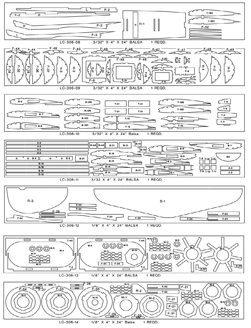
2 Notes about the laser cut parts 1...The first thing that you need to do is to identify and mark the part numbers on the laser cut parts using the drawings on the following pages as a guide. 2...It is possible that several of the laser cut parts may not be completely cut through. If this is the case you can free the part from the sheet quickly using an X-acto knife. 3...The slight discoloration on the edges of the laser cut parts may be removed by lightly sanding the edges with 400 grit sandpaper. Kit Contents: Your kit contains the following parts. Please check your kit for any missing or damaged parts before starting construction. Wood Bag: Qty Name Description LC /16 X 4 X 24 Laser Cut Balsa LC /16 X 4 X 24 Laser Cut Balsa LC /16 X 4 X 24 Laser Cut Balsa LC /16 X 4 X 24 Laser Cut Balsa LC /16 X 4 X 24 Laser Cut Balsa LC /16 X 4 X 24 Laser Cut Balsa LC /16 X 4 X 24 Laser Cut Balsa LC /32 X 4 X 24 Laser Cut Balsa LC /32 X 4 X 24 Laser Cut Balsa LC /32 X 4 X 24 Laser Cut Balsa LC /32 X 4 X 24 Laser Cut Balsa LC /8 X 4 X 24 Laser Cut Balsa LC /8 X 4 X 24 Laser Cut Balsa LC /8 X 4 X 24 Laser Cut Balsa LC /8 X 4 X 12 Laser Cut Balsa LC mm X 4 X 12 Laser Cut Poplar Ply LC mm X 4 X 24 Laser Cut Poplar Ply LC /32 X 3 X 12 Laser Cut Balsa LC /32 X 3 X 12 Laser Cut Balsa LC /32 X 3 X 12 Laser Cut Balsa LC /32 X 3 X 12 Laser Cut Balsa LC /16 X 3 X 12 Laser Cut Birch Ply LC /16 X 3 X 12 Laser Cut Birch Ply LC /16 X 3 X 12 Laser Cut Birch Ply LC /32 X 3 X 6 Laser Cut Birch Ply Wing Sheet /16 X 3 X 12 Balsa Windshield Plastic x 2 x 8 Acetate K-306 Decal Sheet # K-306 Decal Sheet # K-306 Decal Sheet # K-306 PLAN A K-306 PLAN B Main Wing Spars & Fuselage....3/32 X 3/16 X 18 Balsa Wing Leading Edges /16 sq. X 18 Balsa Stringer Spars / Fuselage Stringers 3/32 sq. X 18 Balsa Fuselage Side Stringers /32 sq. X 24 Balsa Trailing Edge /16 X 3/4 X 18 Balsa Page 2
3 Kit Contents: Your kit contains the following parts. Please check your kit for any missing or damaged parts before starting construction. Hardware Bag Qty Name Description Blind Nuts Blind Nuts Elevator Joiner /8 x 3 Birch Dowel Control Horn Control Horns Sig EZ Hinge Hinges Tail Wheel & Retainer Plastic Tail Wheel & Retainer Aileron Servo & Hatch # 2 X 1/2 Sheet Metal Screws Axles X 1 1/4 Machine Screws Axle Nuts Nuts Top Wing Screws x 1/2 Machine Screws Tailwheel Reinforcement X 1 1/2 Nylon Tape Bottom Wing Screw x 1 Nylon Screw Blind Nut Blind Nut Tailwheel Wire /32 X 3 Music Wire Wing Filler /4 Triangle x 5/ Wing Dowels /8 x 1 1/2 Birch Dowel Misc. Loose Parts Qty Name Description K-306 Front Cabane Strut... Left side K-306 Front Cabane Strut... Right side K-306 Rear Cabane Strut... Left side K-306 Rear Cabane Strut... Right side K-306 Right Landing Gear K-306 Left Landing Gear Additional Items Required ( Not Included in Kit) Note: These are parts that we have used and are familiar with. There are many other brands available and you may substitute other items that you are more comfortable with or have on hand. Qty Name Description Motor Himax HC Brushless Motor Speed Control Castle Creation Thunderbird-18 Electronic Speed Control with connectors matching motor & battery Battery Connector Male Deans Ultra connector Heat Shrink Tube /16 Heat Shrink Tube Tail Pushrods Dubro Micro Pushrod Set ( DuBro # 847) Aileron Pushrods Alien Aircraft 5 pushrod set ( Make from DuBro # 847) Propeller APC 9 X 3.8 SF Propeller Velcro " Velcro Motor Mount Screws X 1/2 Machine Screws Main Wheels DuBro 2 1/4 Super Lite Wheels (DuBro # 225SL) Battery Cell 1250Mah 20C Lipo Battery Covering Material Light Weight Covering Material Plus Trim Colors Radio Channel Radio with 4 micro servos & Receiver with one Y connector. Page 3
4 Page 4
5 Page 5
6 Page 6


 the 1/8 x 3 dowel. Use the stabilizer as a guide.")
7 Building Instructions: General Note: Cover the plans with wax paper before assembling your model to prevent the parts from sticking to the plan. Building the Tail Surfaces: 1... Glue R-2 and R-3 together. Bevel the front edge of R-3 as shown on the plan, and sand the other edges round. Mark the hinge locations and cut the hinge slots in R-1 and R-3. Temporarily install the hinges without glue. Sand the front edge of R-1 round. Leave the other edges square. 2...Bend the tail wheel wire from the 1/32 x 3 music wire. Leave the axle end long. It will be trimmed to length when the tail wheel is installed later. 3...Drill a hole in the rudder for the tail wheel wire at the location shown on the plan. Cut a groove in the front of the rudder for the tail wheel wire to fit into so that it is flush with the front of the rudder. Glue the tail wheel wire into the rudder. 4...Tightly wrap and glue the 1 nylon tape reinforcement into position around the tail wheel wire. Trim any excess and sand the tape smooth Join the elevators (S-2) the 1/8 x 3 dowel. Use the stabilizer as a guide. Trim the dowel if required to achieve the proper length. Bevel the front edge of the S-2 s as shown on the plan, and sand the other edges round. Sand the front and ends of the stabilizer round. Leave the back edge square. Mark the hinge locations and cut the hinge slots. Temporarily install the hinges without glue. Page 7


8 Building the Fuselage: 6...Press four 4-40 blind nuts into the back of F-17. Note...The top and front of F-17 is marked with TF Use a small drop of thin C/A to secure them in place. Press the 8-32 blind nut into F-23. Use a small drop of thin C/A to secure it in place. 7...Position F-16C on F-16A. Use the dashed lines on F-16A to aid in the alignment. When properly positioned, carefully glue the parts together. NOTE: Do not use excess glue and make sure that none squeezes out at the edges marked. If any does, remove it. This is part of the pocket that the landing gear is placed into and excess glue will affect the fit of the landing gear. No Glue No Glue 8...Glue F-16B on top of F-16C. NOTE: Do not use excess glue and make sure that none squeezes out into the slot for the landing gear. If any does, remove it. When the glue is dry, test fit the landing gear legs into the slots by sliding them into the slots. Scrape any excess glue from the slot to be sure that the landing gear slides in easily. DO NOT GLUE THE LANDING GEAR INTO POSITION AT THIS TIME. 9...Glue a 3/32 x 3/16 brace to the top of F-6 and F-15. Cut the braces from one of the 3/32 x 3/16 x 18 strips. Page 8

 between F-2 and F-3, flush with the front of the fuselage.")


9 10...Glue 3/32 sq. braces to the front of F-9 and F-10. Cut the braces from one of the 3/32 sq. x 18 strips. These braces should be positioned flush with the holes in the middle of the formers. The ends should be flush with the outside edges of the formers. Flush Note: cut these braces from an 18 strip. DO NOTUSETHE 24 PIECES Glue the F-2 and F-3 doublers to the inside of the fuselage sides. Use the drawing on the plan and the photo to properly locate the doublers on the fuselage sides. The doublers are on the inside of the fuselage sides. Glue a short piece of 3/32 x 3/16 strip (from the strip used in step #9) between F-2 and F-3, flush with the front of the fuselage. Be sure to make a right hand and a left hand side Glue two 3/32 sq. X 18 stringers to the inside of each fuselage side. One is on the top and one is on the bottom. Use the detail drawing on the plan as a guide to properly position these stringers. The back end of the stringers stop just in front of the slot for former F-8. Be sure to make a right hand and a left hand side Position F-19A flat on your building board. The front has a slight angle and it is important to make sure that this angle is positioned as shown. Place F-19B into position against F-19A as shown. The dashed lines on F-19B should be facing up. Press the pieces tightly together and then glue them securely together. Angle Dashed lines 14...Place F-19C into position against F-19B as shown. Press the pieces tightly together and then glue them securely together. Page 9


10 15...Place F-19D into position against F-19C as shown. The dashed lines on F-19D should be facing up. Press the pieces tightly together and then glue them securely together Place F-19E into position against F-19D as shown. Press the pieces tightly together and then glue them securely together Position F-19F and F-19G on F-19B. Use the dashed lines on F- 19B to aid in the alignment. When properly positioned, carefully glue the parts together by placing a small drop of thin C/A into each hole. NOTE: Do not use excess glue and make sure that none squeezes out at the edges marked. If any does, remove it. This is part of the pocket that the front cabane struts are placed into and excess glue will affect the fit of the cabane struts. F-19F F-19G No Glue 18...Position F-19H and F-19I on F-19D. Use the dashed lines on F- 19D to aid in the alignment. When properly positioned, carefully glue the parts together by placing a small drop of thin C/A into each hole. NOTE: Do not use excess glue and make sure that none squeezes out at the edges as in the previous step. If any does, remove it. This is part of the pocket that the rear cabane struts are placed into and excess glue will affect the fit of the cabane struts. F-19H F-19I Page 10


11 19...Position F-19J on top of F-19F and F-19G. Line up the front, back and ends flush. When properly positioned, carefully glue the parts together by placing a small drop of thin C/A into each hole. NOTE: Do not use excess glue and make sure that none squeezes out into the slots as in the previous step. If any does, remove it. This is part of the pocket that the front cabane struts are placed into and excess glue will affect the fit of the cabane struts Position F-19K on top of F-19H and F-19I. Line up the front, back and ends flush. When properly positioned, carefully glue the parts together by placing a small drop of thin C/A into each hole. NOTE: Do not use excess glue and make sure that none squeezes out into the slots as in the previous step. If any does, remove it. This is part of the pocket that the rear cabane struts are placed into and excess glue will affect the fit of the cabane struts. When the glue is dry, test fit the cabane struts into the slots by sliding them into the slots. Scrape any excess glue from the slot to be sure that the struts slide in easily. DO NOT GLUE THE CABANE STRUTS INTO POSITION AT THIS TIME Lightly tack glue formers F-4, F-6, and servo tray F-5 into position on the left fuselage side with several small drops of thin C/A glue. The narrow end of F-5 is at the back. Be sure that the formers are completely seated against the fuselage sides Place the right fuselage side into position on the formers and square up the fuselage. Glue the right fuselage to the formers with several small drops of thin C/A glue. Be sure that the formers are completely seated against the fuselage sides. Page 11


12 23...Place the tab on F-7 into the slot in one fuselage side. The other side F-7 should be angled forward. Rotate the other end of F-7 back until the other tab fits into the slot in the opposite fuselage side. Adjust the position vertical and aligned with the outside of the fuselage sides and glue into place Use clothes pins to hold the back end of the fuselage together. The ends should be flush and even with each other. Adjust the back end until the fuselage is straight and square. Glue the fuselage sides together. Make sure that the fuselage is square and then completely glue the formers F-4, F-5 and F-6 to the fuselage sides. Be sure that the formers are completely seated against the fuselage sides Place former F-8 into position. Make sure that the fuselage is square and then glue the former to the fuselage sides Place former F-9 into position. Gently squeeze the fuselage sides tightly against the former so that it is completely seated against the fuselage sides and glue in place. Page 12


13 27...Place former F-10 into position. Gently squeeze the fuselage sides tightly against the former so that it is completely seated against the fuselage sides and glue in place Glue F-11 into position on the bottom of the fuselage. Spread and squeeze the sides, and wiggle the formers fore and aft as required to get F-11 to fit in the proper position Glue F-12 into position on the top rear of the fuselage Glue F-13 into position between the fuselage sides. Spread and squeeze the sides as required to get F-13 to fit in the proper position Glue F-14 and F-15 into position between the fuselage sides. Spread and squeeze the sides as required to get them to fit in the proper position. Page 13


14 32...Place the F-16 assembly into position on the bottom of the fuselage as shown. Position tightly against the fuselage sides, F-13 and F- 14. Make sure that the fuselage is straight and square and glue securely into position Carefully cut part way through the outside of the fuselage sides at the front edge of former F-15 as shown. Also cut part way through F- 2 and F-3 on the inside of the fuselage sides Gently pull the front of the fuselage sides together, cracking the wood slightly on the cut lines, so that they angle in. Place F-17 into position on the front of the fuselage sides. Make sure that it is fully seated on the sides. Tack glue to each side with several small drops of thin C/A glue Glue a strip of velcro to the top of F-18. The front end of F-18 should angle as shown when the top is facing up. angle 36...Place F-18 into the front of the fuselage. Make sure that it is seated completely down in the formers. Wiggle F-17 gently left and right while pushing F-18 forward until it matches the angle and is tight against F-18. Now glue F-18 to F-13, F-14 and F-15. Do not glue to F-17 at this time. Page 14


15 37...Glue F-19 into position on the top of the fuselage. Spread and squeeze the sides as required to get F-19 to fit in the proper position. Be sure the plywood cabane mounts are completely seated Place F-20 into position. The angle on the front should match the angle on F-17. Glue F-20 into position. Now thoroughly glue F-17 to the fuselage sides, F-19, F-20 and F-18. Also apply glue into the cuts / cracks in the fuselage sides Glue parts F-21 to the inside of the fuselage sides (F-3). There are two F-21 s on each side. The outside edges should be flush with F-3 and the back ends should be tight against F Glue parts F-22 to the inside of the F-21 s on each side. The outside edges should be flush with F-3 and the back ends should be tight against F-7. Page 15


16 41...Place F-23 into position between the F-21 s. Pull it up tight against the F-22 s until tightly in position. Glue it securely into position Place parts F-24 into position on the outside of each fuselage side. Match the curve to the fuselage side and glue into position Glue two pairs of F-25 s together. Carefully line up the slots by temporarily inserting the top of the landing gear legs into the slots. Do not glue the landing gear to the F-25 s Place the F-25 s on the ends of F-16 on each side of the fuselage. Carefully line up the slots by temporarily inserting the top of the landing gear legs into the slots. Glue the F-25 s to F-16. Do not glue the landing gear in place at this time Glue two pairs of F-26 s together. Glue two pairs of F-27 s together. Carefully line up the slots by temporarily inserting the cabane struts into the slots. Do not glue the cabane struts in place at this time. Page 16


17 46...Place the F-26 s on the ends of F-19D on each side of the fuselage. Carefully line up the slots by temporarily inserting the cabane struts into the slots. Glue the F-26 s to F-19. Do not glue the cabane struts in place at this time. Place the F-27 s on the ends of F-19B on each side of the fuselage. Carefully line up the slots by temporarily inserting the cabane struts into the slots. Glue the F-27 s to F-19. Do not glue the cabane struts in place at this time Glue former F-28 into position on the top of the fuselage. It should be 90 degrees to the fuselage top Glue formers F-29 thru F-31 into position on the top of the fuselage. These formers should be 90 degrees to the fuselage top Place parts F-32 into position on F-12 at the back of the fuselage top. Place a scrap of 1/8 balsa sheet between them to maintain the proper spacing. Make sure that the top front edges of the F-32 s are centered on the back of F-31. Glue the F-32 s to the fuselage top and the back of F-31. Do not glue the spacer Place two parts F-33 into position on the outside of each F-32. Glue them to F-12, F-31 and F-32. Place two parts F-34 into position on the outside of each F-33. Glue them to F-33 and F-31. Page 17


18 51...Glue formers F-35 thru F-37 into position on the top of the fuselage. These formers should be 90 degrees to the fuselage top Glue formers F-38 and F-39 into position on the bottom of the fuselage. F-38 should be vertical and not 90 degrees to the fuselage bottom. F-39 should be 90 degrees to F Glue formers F-40 thru F-43 into position on the bottom of the fuselage. They should be vertical and not 90 degrees to the fuselage bottom Using three 3/32 sq. x 18 balsa strips, install the bottom middle stringers into position between former F-7 and the end of the fuselage. Make sure that they are fully seated in the slots in the formers and glue them into place. When the glue is dry, trim the front ends flush with the front face of F-7. Note: Use 18 strips to make these stringers. DO NOTUSETHE 24 Pieces until step # Using 3/32 sq. x 18 balsa strips, install the remaining bottom stringers into position. The back end of these stringers stop at the locations shown. Make sure that they are fully seated in the slots in the formers and glue them into place. When the glue is dry, trim the front ends flush with the front face of F-7. Page 18


19 56...Using 3/32 sq. x 18 balsa strips, install the bottom front stringers into position between former F-13 and F-17. Make sure that they are fully seated in the slots in the formers and glue them into place. When the glue is dry, trim the front ends flush with the front face of F-17 and the back end flush with the back face of F Using 3/32 sq. x 18 balsa strips, install the top front stringers into position between former F-37 and F-17. Make sure that they are fully seated in the slots in the formers and glue them into place. When the glue is dry, trim the front ends flush with the front face of F-17 and the back end flush with the back face of F Using 3/32 sq. x 18 balsa strips, install the top rear stringers into position between former F-28 and F-31. Make sure that they are fully seated in the slots in the formers and glue them into place. When the glue is dry, trim the front ends flush with the front face of F Glue formers F-44 thru F-51 into position on both sides of the fuselage. Page 19


20 60..Place two F-52 s in position on each side of the rear fuselage. The top edge is lined up with the lower dashed line and the front is tight against F-51. When in the proper position, glue them to the fuselage sides. 61..Place two F-53 s in position on each side of the rear fuselage. The slot in F-53 is lined up with the pushrod slot in the fuselage side and the front is tight against F-51. When in the proper position, glue them to the fuselage sides. 62..Using the six 3/32 sq. x 24 balsa strips, install the side stringers into position between former F-17 and the rear of the fuselage. You should trim a slight angle on the back side of the stringers at the rear, so they fit flush against the fuselage side. Make sure that they are fully seated in the slots in the formers and glue them into place. When the glue is dry, trim the front ends flush with the front face of F Place part F-55 on top of part F-54. Line up the tabs so the small tab is at the top and the large tab is on the right side. Use a ball point pen to mark the inside notch locations from F-55 onto F-54. mark 64...Remove F-55. Apply some thin C/A glue to the marked areas on F-54 to harden the wood. Allow the glue to soak into the wood and then quickly wipe off any excess from the surface. You can poke small holes into the wood with a straight pin to allow the glue to penetrate into the wood. When the glue is dry, sand the front surface smooth to remove any glue from the surface. harden Page 20


21 65...Flip F-55 over so the small tab is at the top and the large tab is on the left side. Place it on top of F-56. Use a ball point pen to mark the inside notch locations from F-55 onto F-56. mark 66...Remove F-55. Apply some thin C/A glue to the marked areas on F-56 to harden the wood. Allow the glue to soak into the wood and then quickly wipe off any excess from the surface. You can poke small holes into the wood with a straight pin to allow the glue to penetrate into the wood. When the glue is dry, sand the front surface smooth to remove any glue from the surface. harden 67...Flip F-55 over so the small tab is at the top and the large tab is on the right side. Position and glue it into place on top of F-54. Apply the glue sparingly and do not allow the glue to build up in the notch areas. Remove any glue that has built up in the notches Position and glue F-56 into place on top of F-55. Apply the glue sparingly and do not allow the glue to build up in the notch areas Place this nose ring assembly on the front of the fuselage. Position so that the the small tab is at the top and the large tab is on the right side. Line up the inside of the nose ring with the dashed circle on F- 17. When properly positioned, glue the assembly to F-17. Page 21


 into")


22 70...Cut on the dashed lines and remove the hatch opening in F-19E Glue F-57 to the bottom of the tab on F-19D Completely remove former F-6 from the fuselage assembly Securely pin the hatch bottom (H-1) into position on the top of the fuselage. It should be centered left and right with any extra width extending equally on each side of the fuselage Cut four 3/8 long pieces of 3/32 x 3/16 balsa from the 18 strip used to make the braces in step #9. Page 22


23 75...Position these four pieces on the bottom of the hatch. They should be tight against the cutout edges of F-19. Stick them on the point of your hobby knife. Apply a tiny drop of thick C/A and place them on the bottom of the hatch being careful not to glue them or the hatch to F-19. Use just enough glue to tack them in place Remove H-1 from the fuselage and thoroughly glue these locator strips to H-1 with thin C/A Position H-1 back on the fuselage. Place folded strips of wax paper at the front and back end to protect the fuselage from glue Place parts H-2 and H-4 into position at the front and back. Hold these parts tightly against the fuselage formers and glue them to H Remove the hatch from the fuselage. Position H-6 onto the hatch. It should be between the dashed lines and centered left and right. When in the proper position, glue H-6 in place. Page 23


24 80...Position the remaining H-2 and both H-3 s on the hatch. These formers should be 90 degrees to H-1. When in the proper position, glue them in place Glue the hatch stringers into position using short pieces of 3/32 sq. strips remaining from the fuselage. When the glue is dry, trim the stringers flush with the formers Place the hatch on the fuselage. Use a 1/32 drill bit to drill a pilot hole through the hatch into the fuselage. Temporarily install the #2 x 1/2 hatch screw. Trim the screw so that it does not extend past the bottom of F-57. This will prevent the screw from making contact with the battery. Remove the screw and hatch and place a small drop of glue in the hole in the fuselage (F-19 & F-57) to harden the threads in the wood Place one H-5 into position as shown. It should be in full contact with H-1 and forward against H-2. If the back end is long, trim it slightly so it contacts the front face of H-3. After achieving the proper fit, glue H-5 to H-1 only Moisten the outside of H-5 with an ammonia based window cleaner such as Windex. Allow to soak for a short time and then roll H-5 into position, matching the curvature of the formers. H-5 should be against the face of the formers and flush with the outside edges. When you have H-5 positioned properly, glue it to H-3 and H-2. Page 24


25 85...Position and glue the opposite H-5 in place as you did the first. The front ends should be trimmed so that they meet in the center. Repeat the above steps to sheet the remaining cockpit Attach the hatch to the fuselage. Sand the fuselage smooth all over. Sand the wing saddle area to match the curvature of the fuselage formers. Sand the front end rings to match the fuselage angles and then sand the edges round as shown on the plan.. Building the Dummy Motor: 87...Look at part M-1. It has a small dash on the outside edge. This marks the top front. Flip the part over and and make a line marking the top as on the other side. Soak the tabs with thin C/A glue to harden them. When dry, lightly sand both sides to smooth the glue Look at part M-2. It has a small dash on the outside edge. This marks the top front. Flip M-1 over so the front side is facing up. Position M-2 on M-1 and line up the top marks. When properly positioned, glue the two pieces together. Page 25


26 89...Use your hobby knife to trim an angle on the tabs on part M-1 as shown. Apply a small amount of glue to harden the exposed wood on the angle Glue the two M-3 s together. Position them so the grain on the parts approx. 90 degrees to each other Glue three M-4 s to the front of the M-3 s and glue three M-4 s to the back of the M-3 s Glue two M-5 s to the base of each spoke. Make sure that they are tight against the base (crankcase). Page 26


27 93...Glue a M-6 to one of the spokes, followed by an M-7, an M-6, an M-7, an M-6, an M-7, and finally an M-6 as shown on the plan Glue the M-6 s and M-7 s to the remaining spokes Glue a M-8 to one of the spokes, followed by an M-9, an M-8, an M-9, an M-8, an M-9, and finally an M-8 as shown on the plan Glue the M-8 s and M-9 s to the remaining spokes. The long ends of the M-8 s and M-9 s should point the same direction Trim the excess spokes flush with the top of the cylinder assemblies. Page 27


28 98...Glue six M-11 s together as shown Glue the M-11 assembly on top of one cylinder as shown. The front edge should be flush with the M-8. The flat center should be centered on the cylinder. When the glue is dry, trim the front corner to match the angle of M-8. Now sand the M-11 assembly smooth and round the edges as shown Repeat the previous steps to add the M-11 assembly to each cylinder Temporarily mount the motor to F-17 with 4-40 x 1/2 machine screws Glue the dummy motor assembly to the front of M-2. Use the dashed lines for the proper positioning. When the glue is dry, flip the assembly over. Trim away some of the back side as shown for clearance for the motor wires. You may need to trim more as required in the following steps. Page 28


29 103...Test fit the dummy motor to the fuselage. With the top cylinder rotated to the left, line up the tabs on M-1 with the openings in F-56. Press the assembly into the slots in F-56. Do not force it into position. If there is any resistance, see where the tight fit is and sand the tabs as required. You may have to trim more from the back to clear the motor wires. Top cylinder When the dummy motor is fully seated in the slots in F-56, Gently rotate it clockwise until it stops and the top cylinder is vertical. Do not force it into position. If there is any resistance, see where the tight fit is and sand the tabs as required. Top cylinder The final desired fit is when the motor can be inserted and rotated with some friction. This friction is needed to hold the motor in place, so it does not rotate on the finished model during flight Sand a taper on the front of M-10 as shown Glue M-10 to the front of the motor assembly. Be sure that the propeller shaft is centered in the hole in M Remove the dummy motor from the model. Carefully sand the motor with 400 grit sandpaper. We finished the motor by first applying 2 coats of clear dope, thinned 2 parts thinner to 1 part clear dope. This will seal the wood. When dry, sand again with 400 grit sandpaper. Now paint the crankcase with grey dope and paint the cylinders and the front of M-2 with black dope. Page 29


30 Building the Top Wing: Note: Cover the wing plan with wax paper to prevent the parts from sticking to the plan. Building the Top Center Section: Pin the lower 3/32 x 3/16 lower main spar to the plan. Cut it from one of the 18 long strips. Cut the spar a little long so the ends extend past the T-1 ribs Glue ribs T-1 into position on the main spar. They should be 90 degrees to the building board Cut and glue the upper 3/32 x 3/16 main spar into place. Cut it from the 18 long strip used in step #108. Make sure the ribs maintain 90 degrees to the building board Glue T-2 onto the front face of the main spars and the T-1 ribs. Trim the ends if needed to achieve the proper fit.. Page 30


31 112...Pin the TT spacers to the plan Place the T-3 ribs into position. They should be 90 degrees to the building board. Glue them to the main spars Glue the two T-4 s and T-4A s together Place the T-4 assembly into position. The T-4 s should be on the bottom. It should be tight between the T-1 ribs and forward against the T-3 ribs. When positioned properly, glue it to the T-1 and T-3 ribs. Page 31


32 116...Cut the 3/16 sq. leading edge from one of the 18 long strips. Cut it a little long so the ends extend past the T-1 ribs. Place the leading edge into position on the T-1 ribs and glue into position Place the T-5a s into position on the T-5 s. Line them up with the dashed lines on the T-5 s. The ends should be flush. When properly positioned, glue them together Press the 4-40 blind nuts into the T-5A s. Be sure that they are completely seated and secure them with a small drop of glue Remove the center section from the plan and flip it over. Place the T-6 ribs into position. Use the T-5 s as spacers to establish the proper spacing from the T-1 ribs. The T-5A part should fit tight between the ribs and the T-5 should overlap the ribs. The back end of the rib should be seated down and against the side of the notch in the T- 4 s. Page 32


33 120...When the T-6 ribs are properly positioned, remove the T-5 s glue the ribs to the main spars and the T-4 s Place the T-7 ribs into position. Use the T-5 s as spacers to establish the proper spacing from the T-1 ribs. The T-5A part should fit tight between the ribs and the T-5 should overlap the ribs. The back of the T-7 ribs should be centered vertically on the front of T When the T-7 ribs are properly positioned, remove the T-5 s glue the ribs to the front of T-2 and to the leading edge Place the T-8 ribs into position. The back of the T-8 ribs should be centered vertically on the front of T-2. When the T-8 ribs are properly positioned, glue the ribs to the front of T-2 and to the leading edge Place the T-5 s into position. The T-5A s should fit down between the ribs and the T-5 s should fit in the notches in the ribs. When the T-5 s are properly positioned, securely glue them in place with several applications of thin C/A. Page 33


34 125...Place the two T-9 s into position in front of the forward T-5 s. They should be vertical and the bottom edge should be flush with the bottom of T-5. When positioned properly, glue the T-9 s to the T-5 s and the wing ribs Place the two T-10 s into position on the back side of the forward T-5A s. They should be vertical and the bottom edge should be flush with the bottom of T-5. When positioned properly, glue the T-10 s to the T-5 s and the wing ribs Place the two T-11 s into position on the front side of the rear T- 5A. They should be vertical and the bottom edge should be flush with the bottom of T-5. When positioned properly, glue the T-11 s to the T- 5 s and the wing ribs Pin the center section back into position on the plan, Use the 1/16 x 3 x 12 balsa to sheet the rear top of the center section as shown. The sheet should fit tight against the rear face and be flush with the top of the main spar. The sheet should fit tight against the front face and be flush with the top of T-4. The ends can be a little long so they extend slightly past the T-1 ribs. When positioned properly, glue the sheet to the main spar, T-4, and all of the wing ribs Remove the center section from the plan, Use the 1/16 x 3 x 12 balsa to sheet the rear bottom of the center section as shown. The sheet should fit tight against the rear face and be flush with the main spar. The sheet should fit tight against the front face and be flush with T-4A. The ends can be a little long so they extend slightly past the T-1 ribs. Cut the sheet around T-5 and T-11. When positioned properly, glue the sheet to the main spar, T-4A, and the wing ribs. Page 34


35 130...Use the 1/16 x 3 x 12 balsa to sheet the forward top of the center section in three pieces as shown. The first sheet should fit tight against the front face and be flush with the top of the main spar. The sheet should fit tight against and be flush with the 3/32 stringer spar. The ends can be a little long so they extend slightly past the T-1 ribs. When positioned properly, glue the sheet to the main spar, stringer spar, and all of the wing ribs. Install the second sheet between the stringer spars and the third between the stringer spar and the leading edge Use the 1/16 x 3 x 12 balsa to sheet the forward bottom of the center section as shown. The sheet should fit tight against the front face and be flush with the main spar. The sheet should fit tight against the leading edge. The ends can be a little long so they extend slightly past the T-1 ribs. Cut the sheet around T-5 and T-10. When positioned properly, glue the sheet to the main spar, leading edge, and all of the wing ribs Trim and sand the sheet, main spars and stringer spars flush with the outside of the T-1 ribs Sand the center section smooth all over. Round the leading edge to the shape shown on the plan. Sand the T-4 assembly to match the taper at the back of the ribs and sand the back edge round to match the shape shown here and on the plan. Building the Top Right Wing: Glue a T-19 and T-20B to the end of one of the 1/16 x 3/4 x 18 balsa strips. Glue a T-19 and T-20T to the end of one of the 1/16 x 3/4 x 18 balsa strips. When the glue is dry, trim and sand the 3/4 balsa strips to the shape shown on the plan. Page 35


36 135...Pin the lower 3/32 x 3/16 x 18 lower main spar to the plan. The outboard end stops at the T-18 rib. Leave the inboard end long, extending past the T-13 rib Pin and glue rib T-12 into position on the bottom spar 90 degrees to the building board Glue shear web A into position against the front face of the lower spar and rib T-12 as shown on the plan. The small X on the shear web marks the top outboard corner of the shear web Pin and glue rib T-13 into position. The top of the rib should angle slightly toward the wing tip and be in full contact with the shear web Pin and glue ribs T-14 and T-15 into position on the bottom spar 90 degrees to the building board. Page 36


37 140...Glue shear web D into position against the front face of the lower spar and rib T-15 as shown on the plan. The small X on the shear web marks the top outboard corner of the shear web Glue ribs T-16A, T-16B and T-16C together as shown Pin and glue rib T-16 into position. The top of the rib should angle slightly toward the wing tip and be in full contact with the shear web Pin and glue rib T-17 into position on the bottom spar 90 degrees to the building board. Pin Rib T-18 into position. The support tabs should sit on the hatched areas on the plan. It should be 90 degrees to the building board and is not glued to anything at this time Position and glue the top 3/32 x 3/16 x 18 top spar on the wing. The outboard end stops at the T-18 rib. Leave the inboard end long, extending past the T-13 rib. Page 37
 on the wing.")

38 145...Glue the shear webs B, C and E into position on the front faces of the main spars. Trim the ends to get the proper fit if needed. The small X marked on the shear web marks the top outboard corners of the shear webs Position the bottom trailing edge (the one with T-20B) on the wing. It fits into the slots in the trailing edge of the wing ribs. The front end of T-20B should be under T-17. Make sure that the trailing edge is completely seated to the ribs and glue in place. Do not glue the front end to T-17 and T-18 at this time Position the 3/16 sq. leading edge into the notches in the front of the ribs. The outboard end stops at rib T-17. Hold it tight against the ribs and glue in place Position the 3/32 sq. stringer spars into the notches in the front of the ribs. The outboard ends stop at rib T-17. When they are in the proper position, glue them to the ribs Cut part way through the top spar even with the outside edge of rib T-17. Crack the spar at the cut and angle the outboard end down to contact the T-18 rib. Position the spar in the slot in the rib and glue it to the rib. Also, place a small drop of glue into the cut on the main spar. Page 38


39 150...Position the top trailing edge (the one with T-20T) on the wing. It fits into the slots on the top of the trailing edge of the wing ribs. The front end of T-20T should line up with T-17. Make sure that the trailing edge is completely seated on the ribs and glue in place. Do not glue the front end to T-17 and T-18 at this time Cut part way through the top trailing edge even with the outside edge of rib T-17. Crack the trailing edge at the cut and angle the outboard end down to contact the T-18 rib. Moisten the top of T-19 and T- 20T with an ammonia based window cleaner such as Windex. Angle the wing tip down into contact with the T-18 rib and glue it to the rib. Roll the front end of T-20T down on top of the T-17 rib. The notch in T-20T should fit on the stringer spar. Glue the wing tip to rib T-17 and also place a small drop of glue into the cut on the trailing edge Remove the wing from the plan. Trim the support tabs from the back end of the wing ribs. Glue the wing tip to the T-17 and T-18 ribs. Cut part way through the bottom spar even with the outside edge of rib T-17. Crack the spar at the cut and angle the outboard end to contact the T-18 rib. Position the spar in the slot in the rib and glue it to the rib. Also, place a small drop of glue into the cut on the main spar Working from the back to the front, glue the top and bottom wing tip pieces together. Align them so that they form a nice even line from front to back as shown Glue the two T-21 pieces to the front of the wing tip and tight against the 3/16 sq. leading edge. Page 39


40 155...Trim the spars, leading edge and trailing edge flush with T-13 at the inboard end of the wing Sand the leading edge of the wing round to match the profile shown on the plan. Sand the edges of the wing tip round. Now sand the wing smooth all over. Repeat steps 134 thru 156 to build the left wing Cut slots in both T-13 ribs at the dashed lines to accept the wing joiner Slide the plywood Joiner (T-22) into the slot in the T-13 ribs. The top outboard corner of the joiner has the angled corner. Slide the joiner in until it contacts the T-12 rib. Make sure the joiner is straight and in full contact with the spars and the shear web and glue in place Cut slots in both T-1 center section ribs at the dashed lines to accept the wing joiner. Page 40


41 160...Test fit the right wing onto the center section. Use 5 minute epoxy to securely glue the joiner into the center section, the spars and the T-2 web. Also glue the ribs together making sure that the leading and trailing edge are even with each other Test fit the left wing onto the center section. Use 5 minute epoxy to securely glue the joiner into the center section, the spars and the T-2 web. Also glue the ribs together making sure that the leading and trailing edge are even with each other Sand the joints between the outer wings and the center section smooth. Sand the entire wing smooth all over. Building the Bottom Wing: Note: Cover the wing plan with wax paper to prevent the parts from sticking to the plan. Building the Bottom Center Section: Glue the B-1A s to the inside of the two B-1 s. Make sure that you make one right hand and one left hand as shown Pin the 3/32 x 3/16 lower main spar to the plan. Cut it from one of the 18 long strips. Cut the spar a little long so the ends extend past the B-1 ribs. Page 41


42 165...Glue ribs T-1 into position on the main spar. They should be 90 degrees to the building board Glue rib T-2 into position on the main spar. It should be 90 degrees to the building board Glue the top 3/32 x 3/16 main spar to the ribs. Cut it from the 18 long strip used in step 164. Cut the spar a little long so the ends extend past the B-1 ribs Glue B-3 into position. It should be tight against the front face of the main spars and the ends should contact the B-1 ribs Slide one of the B-4 s trailing edges into the bottom slots in the back end of the ribs. It should be centered left and right, and fully forward in the slots. When it is in the proper position, glue it to the ribs. Page 42


43 170...Place the other B-4 trailing edge on top of the back end of the ribs. It should be centered left and right, and the back edge should match the lower B-4. When it is in the proper position, glue it to the ribs and the lower B Sand a taper into the two B-4A s as shown Insert the two B-4A s into position between the two B-4 trailing edges. They should be tight against each side of the B-2 rib. When in the proper position, glue them in place Glue the two B-5 s together with the edges flush. There is a small x marked on these parts. The edges with the x should be on top of each other. Glue the B-5A to the front of the B-5 s with the edges flush. The small x should line up with the x on the T-5 s parts Place the B-5 assembly into position. The edge with the small x is the top edge. The B-5A should be in front. It should be centered left and right and fully seated in the cutout in the B-1 ribs. When in the proper position, glue it in place. Page 43


44 175...Use the 1/16 x 3 x 12 balsa to sheet the top rear of the center section as shown. The sheet should fit tight against the rear face and be flush with the main spar. The sheet should fit tight against the front face and be flush with B-4. The ends can be a little long so they extend slightly past the B-1 ribs. When positioned properly, glue the sheet to the main spar, B-4, and the wing ribs Use the 1/16 x 3 x 12 balsa to sheet the top front of the center section as shown. The sheet should fit tight against the front face and be flush with the main spar. The sheet should extend slightly past the front face of B-5. The ends can be a little long so they extend slightly past the B-1 ribs. When positioned properly, glue the sheet to the main spar, B-5, and the wing ribs Remove the center section from the plans. Trim off the supports from the bottom rear of the ribs. Use the 1/16 x 3 x 12 balsa to sheet the bottom rear of the center section as shown. The sheet should fit tight against the rear face and be flush with the main spar. The sheet should fit tight against the front face and be flush with B-4. The ends can be a little long so they extend slightly past the B-1 ribs. When positioned properly, glue the sheet to the main spar, B-4, and the wing ribs Use the 1/16 x 3 x 12 balsa to sheet the bottom front of the center section as shown. The sheet should fit tight against the front face and be flush with the main spar. The sheet should extend slightly past the front face of B-5. The ends can be a little long so they extend slightly past the B-1 ribs. When positioned properly, glue the sheet to the main spar, B-5, and the wing ribs Trim and sand the sheet flush with the B-1 ribs. Sand the center section smooth all over and round the trailing edge. Page 44


45 180...Cut two pieces of 1/8 dowel to a length of approximately 3/4. Insert them into the holes in W-5. They should stick out 1/4. Securely glue the dowels into position Cut slots in both B-1 center section ribs at the dashed lines to accept the wing joiner Slide the B-6 plywood Joiners into the slots in the B-1 ribs. The top outboard corner of the joiner has the angled corner. Slide the joiners in until they contact the B-2 rib. Make sure the joiners are straight and in full contact with the spars and the shear web and glue in place with 5 minute epoxy Test fit the wing center section onto the fuselage. You can adjust the holes in F-13 if required for a good fit. Sand the back end if required to fit tightly down into the step in the fuselage Place the B-7 disc onto the nylon screw and thread it into place. Glue the B-7 to the center section. Page 45


46 185...Glue the BC filler into position to the bottom of the center section as shown. Do not glue it to the fuselage. Sand it flush with F-13 and taper it back to blend into the wing on it s back side Remove the center section from the fuselage. Cut two holes in the top sheet for the aileron servo wires. Building the Bottom Right Wing: Pin the lower 3/32 x 3/16 x 18 lower main spar to the plan. The outboard end stops at the B-14 rib. Leave the inboard end long, extending past the B-8 rib Pin and glue rib B-7 into position on the bottom spar 90 degrees to the building board Glue shear web F into position against the front face of the lower spar and rib B-7 as shown on the plan. The small X on the shear web marks the top outboard corner of the shear web. Page 46


47 190...Pin and glue rib B-8 into position. The top of the rib should angle slightly toward the wing tip and be in full contact with the shear web Pin and glue ribs B-9, B-10, and B-11 into position on the bottom spar 90 degrees to the building board Glue shear web J into position against the front face of the lower spar and rib B-11 as shown on the plan. The small X on the shear web marks the top outboard corner of the shear web Glue ribs B-12A, B-12B and B-12C together as shown Pin and glue rib B-12 into position. The top of the rib should angle slightly toward the wing tip and be in full contact with the shear web. Page 47
 on the wing.")


48 195...Pin and glue rib B-13 into position on the bottom spar 90 degrees to the building board. Pin Rib B-14 into position. The support tabs should sit on the hatched areas on the plan. It should be 90 degrees to the building board and is not glued to anything at this time Position the top trailing edge (B-15) on the wing. It fits into the slots in the trailing edge of the wing ribs. The aileron cutout in B-15 should be flush with the B-9 rib. The cutout in B-15 for the cabane strut should line up with the hole in B-12. The outboard end should be flush or a little past rib B-13 and the inboard end will probably extend past rib B-8. When the trailing edge is in the proper position, glue it to the wing ribs Position the 3/32 x 3/16 x 18 top spar on the wing. The outboard end stops at the B-14 rib. Leave the inboard end long, extending past the B-8 rib. Glue the spar into place Glue the shear webs G, H and I into position on the front faces of the main spars. Trim the ends to get the proper fit if needed. The small X marked on the shear web marks the top outboard corners of the shear webs. Page 48


49 199...Position the 3/16 sq. leading edge into the notches in the front of the ribs. The outboard end stops at rib B-13. Hold it tight against the ribs and glue in place Position the 3/32 sq. stringer spars into the notches in the front of the ribs. The outboard ends stop at rib B-13. When they are in the proper position, glue them to the ribs Cut part way through the top spar even with the outside edge of rib B-13. Crack the spar at the cut and angle the outboard end down to contact the B-14 rib. Position the spar in the slot in the rib and glue it to the rib. Also, place a small drop of glue into the cut on the main spar Glue the top wing tip parts B-16 and B-17T together as shown Position the top wing tip on the wing. The front and back ends should line up with B-13. Glue the back end to the back of rib B-13. Now glue the wing tip to the back of B-14. Page 49


50 204...Moisten the top of B-16 and B-17T with an ammonia based window cleaner such as Windex. Angle the wing tip down into contact with the B-14 rib and glue it to the rib. Roll the front end down on top of the B-13 rib. The notch in B-17T should fit on the stringer spar. Glue the wing tip to rib B Remove the wing from the plan. Trim the support tabs from the back end of the wing ribs. Cut part way through the bottom spar even with the outside edge of rib B-13. Crack the spar at the cut and angle the outboard end to contact the B-14 rib. Position the spar in the slot in the rib and glue it to the rib Glue the two B-18 s together making sure that the edges are flush all around Position B-18 into position on the wing. It should be tight against the back of the ribs, in full contact with, and flush with the back of the top trailing edge sheet. When properly positioned, glue B- 18 in place Glue B-19 and B-20 together as shown. Position on the bottom of the wing as you did the top trailing edge sheet and glue into place. Page 50


51 209...Glue the lower wing tip parts B-16 and B-17B together as shown Position the lower wing tip on the wing. Glue it to the B-13 and B-14 ribs Working from the back to the front, glue the top and bottom wing tip pieces together. Align them so that they form a nice even line from front to back as shown Glue the two B-21 pieces to the front of the wing tip and tight against the 3/16 sq. leading edge Glue the B-22 and B-23 reinforcements to the inside of B-20 in the locations shown on the plan. Page 51


52 214...Trim the spars, leading edge and trailing edge flush with B-13 at the inboard end of the wing. Sand the leading edge of the wing round to match the profile shown on the plan. Sand the edges of the wing tip round. Leave the edges of the aileron cutout square. Now sand the wing smooth all over. Repeat steps 187 thru 214 to build the left wing. Building the ailerons: Build the Right aileron Glue the two A-2 s together making sure that the edges are flush all around Glue the A-2 onto and flush with the front of A Glue aileron ribs A-3 and A-4 into position on A-1 and against A Glue part A-5 into position between the first two A-3 ribs at the inboard end of the ailerons. Page 52


 on the wing.")

53 219...Trim and sand the top edge of A-2 to match the angle on the A-3 and A-4 ribs With the aileron flat on the building board, Glue the top A-1 into position Draw a line centered on the front of the aileron. Draw a line 1/8 back from the leading edge on the top and bottom of the aileron Use these lines as a guide to trim or sand the proper angles on the front of the aileron as shown on the plan Mark a centerline on the back of the aileron spar (B-18) on the wing. Mark the hinge locations and cut slots in the wing and ailerons for the hinges. Temporarily install the hinges and check the aileron for proper fit on the wing. Do not glue the hinges at this time. Repeat steps 215 thru 223 to build the left aileron. Page 53


54 224...Cut slots in both B-8 ribs at the dashed lines to accept the wing joiner Test fit the wings onto the center section. Use 5 minute epoxy to securely glue wings onto the center section. The joiner should be glued to the spars and the F web. Also glue the ribs together making sure that the leading and trailing edges are even with each other. Sand the joints between the outer wings and the center section smooth. Sand the entire wing smooth all over Draw a line on the piece of 3/4 triangle as shown. Cut straight down on this line to cut the triangle into two pieces Attach the wing to the fuselage. Position the two triangles on the front of the B-8 ribs. They should be tight against the ribs and tight against B-5A. Adjust them up and down so there is a 1/32 gap between the triangle and the fuselage. When properly positioned, glue the triangles to the wing Remove the wing from the fuselage. Sand the triangles to match the profile of the B-8 ribs. Page 54


55 229...Assemble the N struts over the plan using parts N-1, N-2 and N-3. When the glue is dry, sand the edges round and mark the top front end to make positioning on the wing easier Test fit the landing gear onto the fuselage. Clear any excess glue from the slot to allow a good fit. The top of the landing gear have two legs with holes drilled in them. The leg with the three holes is positioned at the front. Do not glue the landing gear to the fuselage at this time Test fit the cabane struts onto the fuselage. Clear any excess glue from the slots to allow a good fit. The front cabanes are the ones that are straight at the bottom bend. The top of the front cabanes angle down at the rear as shown on the plan. The rear cabanes will angle back when seen from the side as shown on the plan. Do not glue the cabanes to the fuselage at this time Attach the top wing to the cabane struts with the 4-40 x 1/2 screws to test the fit. NOTE: When the model is finished and ready to fly, you must use a thread locking compound on these screws Place the landing gear on the fuselage. Attach the bottom wing. Prop up the back end of the fuselage so that it is level measured at the top of F-19 in the hatch area. Using an incidence meter, measure the incidence of the bottom wing. It should be approx. 2 1/2 degrees. Now mount the top wing. Measure the incidence of the top wing. It should also be about 2 1/2 degrees. You want the incidence of the top wing to match the bottom wing. If needed, cut two small square spacers from 1/32 balsa and glue to the bottom of the wing between the wing and the cabanes to adjust the incidence of the top wing so that it matches the bottom wing. Sand the spacers or add more as necessary to achieve the proper angle. Page 55


56 234...Test fit the N struts to the model. The N struts should be loose in the slots in the wings. They will be trapped between the wings but float loosely in the slots in the wings. They should not be tight nor should they change the incidence or put a twist in the wings. Trim and sand the ends of the struts as required to achieve the proper fit. Covering: Sand all parts smooth with 400 grit sandpaper. Feed strings from the aileron servo mounts to the center section. You will use these strings to pull the servo wires thru the wing after the model is covered. Cover the model with a light weight iron on covering material. We used Coverite Microlite Yellow for the Navy version and the wings of the Army version. Krylon Fusion #2330 Sunbeam / Safety yellow Spray Paint matches the Microlite film very well for painting the landing gear and cabane struts. For the Army version, the fuselage was covered with Royal Blue Monokote. Testors # 1211 Gloss Dark Blue was used to paint the landing gear and cabanes to match the Monokote. Note: After the model is covered you must check the tail surfaces, wings and ailerons for warps or twists. If there are any they can be removed by twisting the parts straight and heating the covering. Final Assembly: Place the windshield plastic over the patterns on the plan. Mark the windshield outlines with trim tape or paint Cut the windshields from the plastic. Score the windshields on the bend lines. Bend the windshields to shape Glue the windshields to the hatch in the position shown on the plan. Page 56


57 238...Cut the covering away from the stabilizer, fin and pushrod slots in the back end of the fuselage. Cut the covering away from the stabilizer in the areas that makes contact with the fuselage. Place the stabilizer into position in the fuselage. Make sure that it is straight and square and then glue it into position. NOTE: When trimming the covering, DO NOT cut into the wood. This will cause the tail surfaces to fail in flight Carefully cut the covering away from the area on the fin that will make contact with the fuselage. Place the fin into position and make sure that it is straight and square. Glue the fin into position Attach the elevators with the hinges and glue in place Attach the rudder with the hinges and glue in place Attach the tail wheel with the press on retainer. Trim the axle as required to minimize any play in the tail wheel while still allowing it to rotate freely. Page 57


58 243...Insert the pushrod housings into the exit slots in the back of the fuselage. They should extend out about 1 3/4 from the fuselage side. The front ends of the pushrod housings should pass thru the slot in former F-4. Glue the housings to the rear exits. Do not glue the front ends to the former at this time Screw the rudder and elevator servos to the servo tray. Cut the pushrod housings so they end about 1 from the servo arms Glue the rudder and elevator control horns into position. Drill 1/16 holes for the pins to pass thru. Trim the covering away from the wood in the area where the base of the control horn makes contact. When the glue is dry, cut off the excess pins flush Install the pushrods into the housings from the rear. Secure the rear of the pushrods to the control horns with Mini E/Z Links. Page 58


59 247...The front ends of the pushrods are attached to the servos with Mini E/Z Connectors. Glue the pushrod housings to former F-4. Trim the front ends of the pushrods 3/4 in front of the connectors when the control surfaces are in neutral Secure the receiver to the fuselage side with velcro. Plug the servos into the receiver Attach the motor to the model using 4-40 x 1/2 screws. Use a thread locking compound on the screws Connect the speed controller to the motor. Attach the speed controller to the fuselage side with velcro. Tape the receiver connector wire from the speed controller under F-19 and plug into the receiver Insert the 6-32 x 1 1/4 axle screw into the wheels. Thread one 6-32 nut onto the screw. Tighten the nut finger tight against the wheel. Now loosen the nut about 1/2 turn to provide some play and allow the wheel to turn freely on the axle. Page 59


60 252...Feed the axle thru the landing gear and secure with another 6-32 nut. Make sure the wheel turns freely on the axle. USE A THREAD LOCKING COMPOUND ON THESE NUTS Cut the covering away from the landing gear slots in the fuselage sides. Glue the landing gear legs into the slots in the fuselage with 5 minute epoxy. Wipe away any excess glue before it dries. Check that the wheels are parallel to the fuselage centerline. They should point straight ahead or angle slightly in. Bend the bottom of the gear legs if required to straighten out the wheels Attach the ailerons to the wings with the hinges and glue in place. Make sure that there is an equal gap on each end so the aileron does not rub against the wing Glue the aileron servos into position on the B-42 mounting plates. The servo arms should be angled 30 to 40 degrees forward when the servo is in neutral. Be sure to make a left and a right hand assembly. Page 60


61 256...Screw the servo mount plates to the B-20 s. The servo arms should be forward and outboard as shown. Use the strings in the wing to feed the servo wires through the wing and out the holes in the center section. Glue the aileron control horns to the bottom of the ailerons in the position shown on the plan. Drill 1/16 holes for the pins to fit into Bend the aileron pushrods to the shape shown on the plan. Install the pushrods and attach them to the servos and control horns with with Mini E/Z Links Cut the covering away from the cabane strut slots in the fuselage sides. Glue the front cabane struts into the slots in the fuselage with 5 minute epoxy. Wipe away any excess glue before it dries. The front cabanes are the ones that are straight and the tops angle back when they are in the proper position Glue the rear cabane struts into the slots in the fuselage with 5 minute epoxy. Wipe away any excess glue before it dries. The rear cabanes are the ones that angle back when they are in the proper position Attach the bottom wing onto the fuselage. Plug the aileron servos into a Y connector and then plug the connector into the receiver. Page 61


62 261...Insert the N struts into the bottom wing Attach the top wing with the 4-40 screws. Use a thread locking compound on these screws Attach the dummy motor to the front of the model. It should be held in place with a friction fit WITH THE PROPELLER REMOVED...Turn the transmitter on. Place the throttle stick in the low position. Plug the battery into the speed controller. Check the motor for proper operation and direction of rotation. Follow the instructions with the speed controller to make any adjustments Check the servos for proper operation and direction. Adjust the control throws to the values shown on the plan. Now disconnect the battery and then turn off the transmitter Install the propeller and spinner. Place the battery in the nose of the model and install the hatch Check the balance of the model. It should balance at the position shown on the plan. Move the battery forward or aft to achieve the proper balance. Use the velcro straps to secure the battery in the model in this position. Mark the location of the battery on the fuselage side. This will allow you to quickly reinstall the battery at the location that gives the proper balance. Note: If moving the battery will not achieve the proper balance, you will have to add weight to the nose or tail. Glue any weight securely to the model Your model is now ready to fly. Fully charge the transmitter and airborne battery before attempting to fly the model. Always range check and do a thorough pre-flight of the model before every flight. Always follow established safety guidelines while operating the motor, radio and flying your model. Page 62
Taylorcraft 72 KIT WARRANTY
 Taylorcraft 72 KIT # K-502 Assembly Instructions Revision:02 12-10-13 WARRANTY Alien Aircraft Corp. guarantees this kit to be free from defects in both material and workmanship at the date of purchase.
Your kit contains the following parts. Please check your kit for any missing or damaged parts before starting construction.
 Your kit contains the following parts Please check your kit for any missing or damaged parts before starting construction COMPLETE KIT PARTS LIST 1 Plan Sheet #1 1 Plan Sheet #2 2 Decal Sheet 2 White Tissue
C-180 Builder s Manual
 C-180 Builder s Manual. May 20, 2002 Last revised July 11, 2002 Copyright! 2002 Douglas Binder, Mountain Models www.mountainmodels.com sales@mountainmodels.com (719) 630-3186 1 Required Equipment! Xacto
Citabria Pro. Aerobatic Parkflyer. by Joel Dirnberger
 Citabria Pro Aerobatic Parkflyer by Joel Dirnberger Revision C: December 21, 2004 Citabria Pro Building Instructions Length: Wingspan: Wing Area: Flying Weight: Wing Loading: Functions: Specifications:
Taylorcraft Indoor / Cul-De-Sac Flyer
 Taylorcraft Indoor / Cul-De-Sac Flyer Taylocraft Specifications Wingspan: 28.0 in. Wing Area: 117 sq. in. Weight (Ready to Fly): 3.0 3.1 oz. Wing Loading: 3.7 3.8 oz. / sq. ft. LIABILITY RELEASE In that
LANDING GEAR. 1. Fit landing gear into slots on bottom of fuselage.
 LANDING GEAR 1. Fit landing gear into slots on bottom of fuselage. 4. Use channel-lock pliers to press blind nuts into position (note: drilled hole should be slightly smaller than shaft of blind nut for
FUSELAGE CONSTRUCTION
 FUSELAGE CONSTRUCTION Note: prior to building and gluing on the work surface use protective covering on your building surface. (wax paper or clear wrap) Fit the laser cut Fuselage Front and Fuselage Rear
Sig Mfg. Co., Inc South Front Street...Montezuma, Iowa 50171
 Sig Mfg. Co., Inc...401-7 South Front Street...Montezuma, Iowa 50171 Introduction The SEALANE takes off and lands on water just as easy as the Sig Kadet LT40 does on solid ground. Gentle, graceful, sure
(Build Instructions)
") (Build Instructions) Specifications * Wingspan: 58cm * Length: 50cm * Flying Weight: 59 grams * Channels: 3 (Rudder Elevator Throttle) * Suggested Receiver: 4Ch Micro * Motor: 8mm GearDrive * Prop: GWS
(Build Instructions) Specifications * Wingspan: 58cm * Length: 50cm * Flying Weight: 59 grams * Channels: 3 (Rudder Elevator Throttle) * Suggested Receiver: 4Ch Micro * Motor: 8mm GearDrive * Prop: GWS
ULS Cherokee. Ultra Low Speed aircraft for indoor RC flying. Zippkits. Specifications: Required to complete:
 Zippkits ULS Cherokee Ultra Low Speed aircraft for indoor RC flying. Specifications: Span- 28 inches Wing Area- 151 Sq/In Wing Loading- 3.0 ounces/ft Weight- 3.5 ounces RTF Build time- 1-2 Hours Radio-
ParkJet Builder s Manual
 ParkJet Builder s Manual Thank you for purchasing the ParkJet. The ParkJet is a profile ducted fan airplane that can be flown in a larger park. The ParkJet was initially designed by Scott Stoops and modified
Dandy Sport Builder s Manual
 Dandy Sport Builder s Manual Thank you for purchasing the Dandy Sport. The Dandy Sport has been designed as an easy to build aileron trainer. Take your time and enjoy building this plane. Specifications:
MercurE Mini Old Timer Electric Model
 MercurE Mini Old Timer Electric Model MercurE Specifications Wingspan: 31.6 in. Length: 20.6 in. Wing Area: 153 sq. in. Weight (Ready to Fly): 4.9 to 5.4 oz. Wing Loading: 4.6 5.1 oz. / sq. ft. Version
1/6 PA-25 PAWNEE. *Specifications are subject to change without notice.*
 1/6 PA-25 PAWNEE INSTRUCTION MANUAL [ A335 Kit ] Wing Span : 72 in / 1830 mm Wing Area : 736 sq in / 47.5 sq dm Flying Weight : 6.6 lbs / 3000 g Fuselage Length : 48 in / 1220 mm Requires : "Glow Power"
The Olympic DLG. (Discus launch glider) by Chris Brislin
 by Chris Brislin") The Olympic DLG (Discus launch glider) by Chris Brislin 1 Contents Parts List/ What you need 3 Before you begin 4 Wing Construction 5-9 Pod Construction 9-13 Tail assembly 13-? Control linkages 9-10 Finishing
The Olympic DLG (Discus launch glider) by Chris Brislin 1 Contents Parts List/ What you need 3 Before you begin 4 Wing Construction 5-9 Pod Construction 9-13 Tail assembly 13-? Control linkages 9-10 Finishing
SwitchBack Senior. SwitchBack Senior Specifications
 SwitchBack Senior SwitchBack Senior Specifications Wingspan: 55.4 in. Length: 41 in. Wing Area: 597 sq. in. Weight (Ready to Fly): 34 to 37 oz. Wing Loading: 8.2 to 8.9 oz. / sq. ft. Version 1.05, March
E-AERO EPP PITTS KIT From BP HOBBIES. Parts Included in kit
 E-AERO EPP PITTS KIT From BP HOBBIES Parts Included in kit Thank you for purchasing the BP Hobbies/E-aero EPP Pitts. Please take the time to read through the instruction manual before beginning the build.
S.E.5a (Build Instructions)
") S.E.5a (Build Instructions) Specifications Wingspan: 38 cm Length: 31cm Flying Weight: 41 Channels: 3 (Rudder Elevator Throttle) Suggested Receiver: 3Ch Brick Motor: 7mm Geared Motor Airframe Only Kit
S.E.5a (Build Instructions) Specifications Wingspan: 38 cm Length: 31cm Flying Weight: 41 Channels: 3 (Rudder Elevator Throttle) Suggested Receiver: 3Ch Brick Motor: 7mm Geared Motor Airframe Only Kit
Switchback Sport Builder s Manual
 Switchback Sport Builder s Manual Thank you for purchasing the Switchback Sport. The Switchback Sport has been designed for the novice to intermediate pilot who wants a plane with good performance that
Thank you for your purchase of the Lee Ulinger, FoamtanaS, Yak-55, or Extra 330 3D Depron foam, Aerobatic airplane.
 Thank you for your purchase of the Lee Ulinger, FoamtanaS, Yak-55, or Extra 330 3D Depron foam, Aerobatic airplane. Tools you will need to build Recommended additional items: #11 hobby knife Motor: Hacker
LoLo. A sporty parkflyer with an Old Timer flair! Designed by: Tres Wright Kitted by: Park Scale Models
 LoLo A sporty parkflyer with an Old Timer flair! Designed by: Tres Wright Kitted by: Park Scale Models http://www.parkscalemodels.com/ Assembly Instructions General Information The laser cutting process
SPUNKY ASSEMBLY MANUAL
 SPUNKY ASSEMBLY MANUAL Please read the tips section at the back of this manual regarding the use of laser cut parts. The proper removal and preparation of these parts is important. When laser cut, some
Piper Cherokee /3 scale. Construction Manual
 Piper Cherokee 140 1/3 scale Construction Manual STAB CONSTRUCTION 1. Remove foam cores from cradle and place on flat surface. Inspect pieces before you epoxy halves together making sure leading and trailing
Fokker Dr1 Master Instructions
 Fokker Dr1 Master Instructions Rev 1 Congratulations on your new project. This Dr1 kit is the finest to date. The construction of the plane is similar and exactly like the original. Take your time and
Parts Identification
 We are excited to introduce the Model Aero Aqua Sport. This is an excellent sport flyer, equally at home flying from grass fields, water, or even snow! The unique V-tail gives the Aqua Sport a distinctive
MOUNTAIN MODELS P-51 Mustang. 1/12 Scale Electric Park Flyer. Copyright Mountain Models
 1 MOUNTAIN MODELS www.mountainmodels.com P-51 Mustang 1/12 Scale Electric Park Flyer Wingspan: 37, Wing Area: 254 sq. in., Weight: 15 to 19.5 oz Instructions Version 1.4, May 23, 2007 Kit Contents: 2 1.
SZD-10 bis CZAPLA ASSEMBLY MANUAL IN PICTURES
 1 RUDDER Plan and parts: 2 Assembly steps: Photo above: glue together rudder spar, ribs and trailing edge. Clamp spar to a flat surface (chipboard on the photo) and make sure the straight aligment of the
THE APOGEE A 100-INCH AMA DURATION SAILPLANE FROM DYNAFLITE
 THE APOGEE A 100-INCH AMA DURATION SAILPLANE FROM DYNAFLITE Apogee is the intermediate sailplane designed to be competitive in AMA duration contests. Effective spoilers, rudder and full flying stabilizer
WRIGHT FLYER 1 INSTRUCTIONS FOR THE D10LC KIT
 WRIGHT FLYER 1 INSTRUCTIONS FOR THE D10LC KIT Manufactured in the USA by Easy Built Models PO Box 681744, Prattville, AL 36068-1744 Visit us at www.easybuiltmodels.com Easy Built Models GLUE METHODS Always
RESolution V2 Manual
 RESolution V2 Manual Note for the German Manual: Yellow Bottle thick CA Pink Bottle Med CA Blue tube 5 minute Epoxy Green tube 90 Minute Epoxy Construction of the Fuselage Step 1: Cover the plan with a
RYAN STA SAFETY PRECAUTIONS. "Sport Scale E-Power ARF" For Intermediate and Advanced Fliers. This radio control model is not a toy!
 RYAN STA "Sport Scale E-Power ARF" For Intermediate and Advanced Fliers. SAFETY PRECAUTIONS This radio control model is not a toy! First-time builders should seek advice from people with model building
Millennium RC presents The New and Improved (now even easier to build and cover!) SSX X-Trainer Build Kit
 SSX X-Trainer Build Kit") Millennium RC presents The New and Improved (now even easier to build and cover!) SSX X-Trainer Build Kit Wing span: Approx. 42 Wing Area: 504 sq. in. Wing Loading: 6.71 oz/ sq. ft. Introduction: The Slow
Millennium RC presents The New and Improved (now even easier to build and cover!) SSX X-Trainer Build Kit Wing span: Approx. 42 Wing Area: 504 sq. in. Wing Loading: 6.71 oz/ sq. ft. Introduction: The Slow
BUILDING THE A6M2 ZERO
 BUILDING THE A6M2 ZERO Product Support (Do Not Remove From Department) TOP FLITE MODELS, INC CONGRATULATIONS' You now own the most accurate R/C Stand-Off Scale kit ever produced We at Top Flite hope that
GYM-E. Instruction Manual - Version 1.03
 GYM-E Original Design by Todd Long Instruction Manual - Version 1.03 Span 31 in. / Length 27 in. / Area 265 Sq. In. / Weight 4.5-6.5 oz. Gym-E kit reproduced with permission by Stevens AeroModel 2008 Stevens
Hobby Lobby Zip Supplementary instructions Please refer to the included drawings while using these assembly instructions
 Materials needed: 15 or 30 minute epoxy Medium CA Masking tape Scotch tape Servo Tape Wax paper Tools Needed: Pencil or marker Flat building surface Hobby knife or razor blade 7/64" or 3mm drill bit 3/16"
PITTS S2S CONSTRUCTION
 PITTS S2S CONSTRUCTION FUSELAGE CONSTRUCTION 1) Place the right fuselage side over the plan and mark the former positions. Place the left side over the right side and mark the former positions. Glue F1
Pfalz E1 Monoplane 48 EZ Build Version
 Pfalz E1 Monoplane 48 EZ BUILD Pfalz E1 Monoplane 48 EZ Build Version R/C Scale Model Instructions CONTACT INFORMATION Designed by M.K. Bengtson Prototype by Robert Hoffman Manufactured and Distributed
Messerschmitt Bf 109F-2 Version January 2005
 Assembly Manual for Messerschmitt Bf 109F-2 Version 1.2 29 January 2005 Designed by Terry Majewski Copyright 2005 Thomas A. Jacoby and WarbirdKits.com 1 Materials Kit Contents This kit includes the following
4. Bevel the LE face of HS1-HS11 to match the horizontal stab leading edge sweep angle.
 BEFORE YOU BUILD 1. Unroll each sheet of the plans. Roll them inside out so that they will lie flat on the building surface. 2. Assemble the tools that you will need to build each section so that they
Instruction Manual book
 Instruction Manual book ITEM CODE BH53. SPECIFICATION Wingspan : 1,250mm 49.21 in. Length : 930mm 36.61in. Weight : 1.1kg 2.42 Lbs. Parts listing required (not included). Battery: 3 CELLS-LI-POLY-11.1V-2,500
PT Military Trainer. R/C Scale Model Instructions CONTACT INFORMATION
 PT Military Trainer R/C Scale Model Instructions CONTACT INFORMATION The PT Military Trainer was designed by: M.K. Bengtson Prototype by: Brian Allen Manufactured and Distributed by: Bengtson Company e
JAMISON SPECIAL. Building Guide
 JAMISON SPECIAL Building Guide WING Mark then drill holes for wing jig rods. Slide Ribs onto jig rods Mark the rib positions on 1/16 x 1 trailing edge, 1/4 x 1/4 leading edge & 1/4 x 1/4 spars Pin ribs
TIGER MOTH 120 ASSEMBLY INSTRUCTIONS
 TIGER MOTH 120 ASSEMBLY INSTRUCTIONS SPECIFICATIONS Wing Span: Length: Radio: Flying Weight: 1920mm 1580mm 4 channel with 6 servos 4200g AILERON ASSEMBLY 1 Start by removing the servo cover from the bottom
LANIER - Ultimate Pitts - INSTRUCTIONS. Additional Parts Required. (12) 4-40 blind nuts (Dubro #606)
 4-40 blind nuts (Dubro #606)") Additional Parts Required (4) or more channel radio with 7-8 servos..91-2.2 two stroke or 1.20-1.84 four stroke engine Appropriate Master Airscrew prop and Hayes mount for your engine. 3 Tru-Turn spinner
Additional Parts Required (4) or more channel radio with 7-8 servos..91-2.2 two stroke or 1.20-1.84 four stroke engine Appropriate Master Airscrew prop and Hayes mount for your engine. 3 Tru-Turn spinner
LARK. Classic Legal Precision Stunter RSM DISTRIBUTION. presents. Charles Mackey. Wing Area 570sq. Wingspan 52.
 RSM DISTRIBUTION presents LARK By Charles Mackey Photo _ Bob Hunt Classic Legal Precision Stunter Wingspan 52 Length 39.5 Wing Area 570sq Motor 35-46 www.rsmdistribution.com Page 2 Thank you for purchasing
F100 Super Sabre instructions.
 F100 Super Sabre instructions. The F100 is a Jet model for the Wemotec 480 Minifan. Start with taking the parts out of the sheet and sand of the connection tabs. Instructions RBCkits F100 Super Sabre 1
INCLUDED IN THIS KIT: SPECIFICATION: NEEDED BUILDING TOOLS: REQUIRED EQUIPMENT:
 Please review this entire manual before beginning assembly. By doing so it will help you better understand each step as you progress in the actual building of your kit, and you will do a better job in
LANIER - Double Trouble - INSTRUCTIONS. Tail 1 T1 ¼ Balsa 1 T2 ¼ Balsa 2 T3 ¼ Balsa 1 T4 ¼ Balsa 1 T5 ¼ Balsa 1 T6 ¼ Balsa 2 J1 ¼ Balsa 2 J2 Lite ply
 Tail 1 T1 ¼ Balsa 1 T2 ¼ Balsa 2 T3 ¼ Balsa 1 T4 ¼ Balsa 1 T5 ¼ Balsa 1 T6 ¼ Balsa 2 J1 ¼ Balsa 2 J2 Lite ply Other Parts 2 Aluminum Gear 1 3/32 Music wire tail skid 2 Elevator and J-plane joiner wire
Round2it! Mini Electric Sailplane. Round2it
 Round2it! Mini Electric Sailplane Round2it Wingspan: 36.0 in. Length: 22.4 in. Wing Area: 164 sq. in. Weight (Ready to Fly): 4.0 to 4.8 oz. Wing Loading: 3.5 4.2 oz. / sq. ft. Version 1.0, September 10,
Parkflyer F6F Hellcat
 Parkflyer F6F Hellcat Page 1 of 19 MOLT MODELS Background Design Philosophy When I was first introduced to this hobby seventeen years ago I saw my first WWII warbird and I was hooked. Several years later
COMET SENIOR DART REPRODUCTION ASSEMBLY GUIDE
 COMET SENIOR DART REPRODUCTION A RUBBER POWERED 24" WING SPAN MODEL BY PAUL BRADLEY ASSEMBLY GUIDE JANUARY 2018 CHANGES MADE TO THE ORIGINAL The following changes were made to the original Comet kit structural
High performance 90mm fiberglass jet
 High performance 90mm fiberglass jet Assembly manual For intermediate and advanced fliers only! Specs Wingspan: 1255mm Fuselage length: 1250mm Flying weight: 2600-3000g Wing area: 22.6 dm² Wing loading:
HIGH-END TECHNOLOGY. Electric ducted fan Starfighter
 HIGH-END TECHNOLOGY RC Electric ducted fan Starfighter First we want to thank and congratulate you with your decision in buying one of our Kits. The Starfighter puts together very easily so there is not
LANIER Dominator INSTRUCTIONS
 ADDITIONAL EQUIPMENT NEEDED TO COMPLETE YOUR DOMINATOR 500 General 3.2 to 4.2 Size two stroke R/C engine, muffler, and engine mount Gas or glow fuel line Minimum of 4 channel radio set required (4-5) 70
RSM DISTRIBUTION Presents
 RSM DISTRIBUTION Presents MOSQUITO By Jack Sheeks Photo _ Jack Sheeks Semi Scale Twin Stunter Wing Span: 58" Length: 37-3/4 Area: 579 sq. in. Engine: Two.35 -.40 www.rsmdistribution.com Call (951) 678
F-16 Falcon 70mm EDF
 F-16 Falcon 70mm EDF Instruction manual Specifications: Winspan: 640 mm Length: 990 mm Weight: 900-1100 gram Ducted fans 70mm x 1 Required tools and components:. 4 ch. Computer Radio system w/ 2 servos.
A Piaggio-inspired park flyer
 Clark Salisbury's SkyTwin A Piaggio-inspired park flyer B efore I discuss building the SkyTwin, I should explain my reasons for designing, building, and flying such an aircraft. I have always been fascinated
NASTY Build Guide. Supplies needed
 NASTY Build Guide Supplies needed Blucore or Depron Foam. Blucore (Fan Fold Foam) is available at Lowes. Approximately $25 for 50 feet of Blucore. Depron can be ordered on the internet for slightly more.
28in Super EVA Foam. F-22 Raptor Kit. Specifications. Wingspan: 27.5in (700mm) Length: 38.3in (975mm) Flying Weight: Approx. 1.
 Length: 38.3in (975mm) Flying Weight: Approx. 1.") 28in Super EVA Foam F-22 Raptor Kit Specifications Wingspan: 27.5in (700mm) Length: 38.3in (975mm) Flying Weight: Approx. 1.2lbs (530g) Dear Customer, Congratulations on your purchase of 28in F22 Raptor
28in Super EVA Foam F-22 Raptor Kit Specifications Wingspan: 27.5in (700mm) Length: 38.3in (975mm) Flying Weight: Approx. 1.2lbs (530g) Dear Customer, Congratulations on your purchase of 28in F22 Raptor
uin RC FPRC ZERO Specificationss Empty Weight
 Flying Pengu uin RC FPRC ZERO Specificationss Wing Span 42.75 (1085 mm) Fuselage length 30.5 ( 775 mm) Empty Weight 9.5 10 oz. (150 160g) Estimated Flying Weight 20 255 oz. (320 400g) Wing Area: 151 sq.
Magpie. Foam Trainer. Magpie Specifications
 Magpie Foam Trainer Magpie Specifications Length: 34in. Wingspan (SF): 46in. Wing Area (SF): 414in 2 Wingspan (SP): 40in. Wing Area (SP): 360in 2 Weight (without battery): 12oz. Thank you for purchasing
Warbird Series Zero - 32 Assembly Manual
 Warbird Series Zero - 32 Assembly Manual Specifications Wing Span: 32 inches Wing Area: 210 in 2 Fuselage Length: 26 inches Weight (ready to fly): 11 to 13 oz. Wing Loading: 7.5 to 8.9 oz/ft 2 Designed
Roland c.ii Walfisch Ultra Micro Cartoon Scale WW I Electric Model
 Roland c.ii Walfisch Ultra Micro Cartoon Scale WW I Electric Model Roland c.ii Walfisch Wingspan: 13.35 in. Length: 13.4 in. Wing Area: 78 sq. in. Weight (Ready to Fly): 1.4 oz. Wing Loading: 2.6 oz. /
MECOA EZ-4061 Trainer
 MECOA EZ-4061 Trainer EZ-4061 is a newly designed, Almost Ready to Fly kit. It is an extremely easy to control trainer with strong construction and excellent aerodynamic performance. This is a great choice
INCLUDED IN THIS KIT: SPECIFICATION: NEEDED BUILDING TOOLS: REQUIRED EQUIPMENT:
 Please review this entire manual before beginning assembly. By doing so it will help you better understand each step as you progress in the actual building of your kit, and you will do a better job in
Eva. Extremely Versatile Airframe
 Eva Extremely Versatile Airframe Eva Specifications Length: 32 Weight (without battery): ~12oz. Revision History Date Revision Notes/Comments 6/3/05 Document initial creation. Thank you for purchasing
Note - the nose ribs and are thinner than the main ribs. These nose ribs will use a thinner rib cap than the ribs. This is per design.
 Stabilizer rev 1.2 The SE5a stabilizer is the heartbeat of the tail and is recreated like the full scale version. All tail pieces depend on the stabilizer. It uses the steel fittings, pulleys, inspection
Pfalz E1 48. R/C Scale Model Instructions CONTACT INFORMATION. The Pfalz E1 was designed by M.K. Bengtson Prototype by Jack Richardson
 Pfalz E1 48 Pfalz E1 48 R/C Scale Model Instructions CONTACT INFORMATION The Pfalz E1 was designed by M.K. Bengtson Prototype by Jack Richardson Manufactured and Distributed by: Bengtson Company e mail:
Fokker D8 Master Instructions
 Fokker D8 Master Instructions Rev 1 Congratulations on your new project. The Fokker D8 is a marvellous subject that highlights the success of a monoplane design. The construction of the plane is similar
Combat plane for Open B Lanier R/C Inc. P.O. Box 458 Oakwood, GA Phone Fax copyright 2003 Lanier R/C
 Combat plane for Open B Lanier R/C Inc. P.O. Box 458 Oakwood, GA. 30566 Phone 770 532 6401 Fax 770 532 2163 copyright 2003 Lanier R/C Important information: Please inspect the plane before beginning to
FLITZEBOGEN-2 Assembly instructions
 FLITZEBOGEN-2 Assembly instructions Trim the end of the fuselage to the length of 925mm from the nose. Be careful to avoid splitting the carbon fibers. Sand the base of the stab mount in preparation for
R/C Scale Model Instructions
 Vickers 151 Jockey 32.6 Vickers 151 Jockey 32.6 1/12 Scale R/C Scale Model Instructions CONTACT INFORMATION Designed by M.K. Bengtson Prototype by Bert Ayers Manufactured and Distributed by: Bengtson Company
Introducing The Cloud Models Westland Whirlwind
 Produced by Cloud Models,Deopham Road,Morley,Wymondham, Norfolk,NR18 9AA E-mail sales@cloudmodels.com web site cloudmodels.com Introducing The Cloud Models Westland Whirlwind By Tricks Thank you for purchasing
TWEETY 25 INSTRUCTION MANUAL. Almost Ready to Fly Nitro/Electric Aerobat FEATURES SPECIFICATIONS
 TWEETY 25 Almost Ready to Fly Nitro/Electric Aerobat INSTRUCTION MANUAL SPECIFICATIONS FEATURES WINGSPAN: 45.7 (1160mm) LENGTH: 38.6 (980mm) WING AREA: 370 sq in(24 sq dm) FLYING WEIGHT: Approx. 3.3 lbs
96 WING SPAN SPITFIRE (COPYRIGHT PROTECTED 2014) ALL RIGHTS RESERVED
 ALL RIGHTS RESERVED") 96 WING SPAN SPITFIRE (COPYRIGHT PROTECTED 2014) ALL RIGHTS RESERVED GENERAL INSTRUCTIONS Should you elect to use the recommended Door Skin, which is 1/8 mahogany plywood measuring 36 x 88. Have it cut
96 WING SPAN SPITFIRE (COPYRIGHT PROTECTED 2014) ALL RIGHTS RESERVED GENERAL INSTRUCTIONS Should you elect to use the recommended Door Skin, which is 1/8 mahogany plywood measuring 36 x 88. Have it cut
Bogie 72. Old Timer Electric Model. Little Bogie Specifications
 Bogie 72 Old Timer Electric Model Little Bogie Specifications Wingspan: 72.0 in. Length: 39.0 in. Wing Area: 655 sq. in. Weight (Ready to Fly): 28 to 30 oz. Wing Loading: 6.1 6.6 oz. / sq. ft. Version
SE5a Wing Panels rev 1.0
 SE5a Wing Panels rev 1.0 The top and bottom wings are different. They might look the same but the bottom wing has one less rib and some rib spacing difference. This is due to where the wooden interplane
Building Instructions P-51 BF109
 Building Instructions P-51 BF109 Sport model for.015 engines. Legal for SSC Warbird Lanier R/C Inc. P. O. Box 458 Oakwood, Ga. 30566 Copyright 2004 Lanier R/C Inc. Important information: Please inspect
This pictorial document contains assembly recommendations including some fit and finish details that will be helpful when building this airplane
 This pictorial document contains assembly recommendations including some fit and finish details that will be helpful when building this airplane Problems found with this kit and a flight performance review
DRAFT COPY BUILDING INSTRUCTIONS FOR BLACKBURN BUCCANEER S2 VERSION 1 (BETA BUILD) BY MARK DOUGLAS
 BY MARK DOUGLAS") BUILDING INSTRUCTIONS FOR BLACKBURN BUCCANEER S2 VERSION 1 (BETA BUILD) BY MARK DOUGLAS COPYRIGHT MARK DOUGLAS 2011 THIS IS A "SHORT" KIT FOR EXPERIENCED BUILDERS AND FLYERS ONLY, DESIGNED BY A SHED DWELLING
BUILDING INSTRUCTIONS FOR BLACKBURN BUCCANEER S2 VERSION 1 (BETA BUILD) BY MARK DOUGLAS COPYRIGHT MARK DOUGLAS 2011 THIS IS A "SHORT" KIT FOR EXPERIENCED BUILDERS AND FLYERS ONLY, DESIGNED BY A SHED DWELLING
I hope you enjoy the Spirit as much as I have. Scott DeTray Model Aero
 We are excited to introduce the Model Aero Spirit. Inspired by the magnificent Northrop Grumman B-2 Spirit Stealth Bomber, the Spirit is a great flyer, on land or water. It tracks like an arrow and is
Albatros DII. R/C Scale Model Instructions. CONTACT INFORMATION The Albatros DII was designed by M.K. Bengtson
 Albatros DII 36 Albatros DII R/C Scale Model Instructions CONTACT INFORMATION The Albatros DII was designed by M.K. Bengtson Manufactured and Distributed by: Bengtson Company e mail: sales@aerodromerc.com
43in EPP Acrocub Instruction Manual
 43in EPP Acrocub Instruction Manual Specifications Wingspan: 43.3in (1100mm) Length: 41.3in (1050mm) Flying Weight: Approx. 1.5lb (670g) Dear Customer, Congratulations on your purchase of 43in EPP Acrocub
Super Sky Surfer 2000 Assembly Instructions
 Super Sky Surfer 2000 Assembly Instructions Note: Plug and Play version of the Sky Surfer comes with fuselage pre-glued and motor/servos installed. If you wish to route antennas or wires through the tail,
Pfalz E1 36. R/C Scale Model Instructions CONTACT INFORMATION. The Pfalz E1 was designed by M.K. Bengtson Prototype by Ian Easton
 Pfalz E1 36 Pfalz E1 36 R/C Scale Model Instructions CONTACT INFORMATION The Pfalz E1 was designed by M.K. Bengtson Prototype by Ian Easton Manufactured and Distributed by: Bengtson Company e mail: sales@aerodromerc.com
Instruction Manual. Specification:
 Instruction Manual H I G Specification: Wingspan: 133 cm (52.3 inches) Length : 104 cm (40.9 inches) Weight : 1830gr Engine : 25-32 two stroke Radio : 4 channel - 4 servo H W I N G KIT CONTENTS: We have
A record setting motor glider from the 1923 Lympne light aircraft trials.
 1923 Avro 558 A record setting motor glider from the 1923 Lympne light aircraft trials. Wing Span: 33 inches Wing Area: 205 square inches Average Flying Weight: 7 ounces - Version 1.24 (revised 08.21.2014)
Designed in 2005 by Bernard Burton. Assembly manual Bernard Burton DRAFT 1
 Designed in 2005 by Bernard Burton Assembly manual 2005 - Bernard Burton DRAFT 1 The plans can be requested via this link http://www.gundersonaerodesign.com/m12plansreq.htm The laser kit is available here
90 WING SPAN P-51D MUSTANG (COPYRIGHT PROTECTED 2014) ALL RIGHTS RESERVED
 ALL RIGHTS RESERVED") 90 WING SPAN P-51D MUSTANG (COPYRIGHT PROTECTED 2014) ALL RIGHTS RESERVED GENERAL INSTRUCTIONS This design is basically an enlargement of the very popular fun scale Mustang 60 Size. You can build it light
90 WING SPAN P-51D MUSTANG (COPYRIGHT PROTECTED 2014) ALL RIGHTS RESERVED GENERAL INSTRUCTIONS This design is basically an enlargement of the very popular fun scale Mustang 60 Size. You can build it light
1. Build the bottom first - make sure your table is flat. Build the entire plane using foam safe CA and kicker. The best technique is to spray kicker
 Wxá zç uç `tçué 1. Build the bottom first - make sure your table is flat. Build the entire plane using foam safe CA and kicker. The best technique is to spray kicker on one part and apply a sparing amount
Assembly Instructions
 Congratulations AJ Aircra thanks you for the purchase of this airplane. Top grade materials and precision assembly has gone into this to make this a top quality aircra. Following the direcons closely,
25mm EPP SU31. Instruction Manual. Specifications
 25mm EPP SU31 Instruction Manual Specifications Wingspan: 39.4in (1000mm) Length: 42in (1070mm) Wing Area: 448sq in (28.9sq dm) Flying Weight: Approx. 1.5lb (650-710g) Dear Customer, www.valuehobby.com/su31-epp.html
Building a Giant Scale Electric EINDECKER Part 2
 Building a Giant Scale Electric EINDECKER Part 2 John Bernard N1KUB AMA 58903 IMAA 28971 In Part-1 of this series, we explored the 100 Eindecker kit from SR Batteries and started building the fuselage.
COMET 24" HELLCAT REPRODUCTION ASSEMBLY GUIDE
 COMET 24" HELLCAT REPRODUCTION A RUBBER POWERED 24" WING SPAN MODEL BY PAUL BRADLEY ASSEMBLY GUIDE AUGUST 2016 CHANGES MADE TO THE ORIGINAL The following changes were made to the original Comet kit structural
Ryan STA Sport Scale Model Aircraft Assembly and Instruction Manual
 Ryan STA Sport Scale Model Aircraft Assembly and Instruction Manual Warning: This radio controlled model is not a toy. It requires skill to fly and is not recommended for the novice pilot. It should not
A large prop insures high performance. Cleverly designed to give a realistic appearance
 Cleverly designed to give a realistic appearance A large prop insures high performance A Vought Fighter That Flies Complete Data from Which You Can Build an Excellent Performing Flying Scale Model of the
Park Scale Models AT-17 Bobcat Assembly Manual
 Park Scale Models AT-17 Bobcat Assembly Manual Fuselage Construction 1. Glue the two ¼ balsa servo rails SR to BB5. SR BB5 2. Assemble the wing mount block by gluing WM1(x2), WM2 and WM3 together as shown.
The BIPE NX Assembly Manual
 The BIPE NX Assembly Manual Specifications Wing Span: 34 inches Wing Area: 550 in 2 Fuselage Length: 36 inches Weight (ready to fly): 20 to 24 oz. Wing Loading: 5.2 to 6.3 oz/ft 2 Designed by Jim Vigani
Continue gluing the remaining top parts ensuring the angled piece is glued well. Set aside and let dry. See photo below
 Radiator rev 1.1 The SE5a s radiator is one of the most recognized radiators in WW1. It is one of the components that defines the SE5a. The original SE5a has seen multiple radiator designs used during
Revolution 3D-mini ARF
 Revolution 3D-mini ARF 1 Included Hardware 4 Dubro Micro Control Horns #DUB848 2.32 x 18" Linkage Wire (Music Wire) 1 1.5 x 1.25 x 1/8 Balsa Ply (for motor mount) 1 5" piece of Velcro (Optional recommended,