An Easy to Make, Paddle and Transport Family Pram. Print in Landscape Mode with ¼ inch borders. Adult Figure Shown
|
|
|
- Claud Phelps
- 6 years ago
- Views:
Transcription
1 An Easy to Make, Paddle and Transport Family Pram Drawn Rev Print in Landscape Mode with ¼ inch borders. FEATURES: Ultra-Stable Wide Design Simple Flat Side Construction Only 2 Sheets of 1/4 Plywood Adjustable Bench Seating for Two Row, Paddle or Trolling Motor Power Optional Foam Under Seats for Safety Flip-Over Hulls for Easy Transport and Setup Adult Figure Shown The beauty of this design is that it offers the builder different ways to assemble, outfit and finish it, depending on the end use and transport or storage requirements. Can be Motorized Refer to page 26 for 10' River Runner 36 The hull modules can be glued and screwed together for those that do not have transport or storage constrictions. 12 OAL = 96 (8 feet) OAW = 36 (3 feet) OAH = 12 (1 foot) Weight = 50 pounds Capacity = 2 People or 450 pounds a ken simpson design Stacked Folded for Transport End View Skids 50 max 26 max 4 max Waterline Drawings are not to scale. Page 1 of 23 This is an experimental design drawn up by an untrained amateur. The Designer accepts no liability for any loss, harm or damage sustained during construction or use. Builders may use these plans to construct a small quantity of boats for their own use only. Commercial manufacturers must ask the Designer for permission.
2 General Notes The design of the is in response to a request for a low cost, stable, portable boat. It includes a wide beam, good freeboard, generous volume, seating for two, and safety buoyancy. It is sturdy, easy to build, quite portable, easy to paddle and can utilizes a trolling motor. To have strength and yet be lightweight, the plans use some non-traditional methods of assembly, specifically the Tape & Glue construction process developed and incorporated by the designer. This provides a durable, yet truly portable, finished boat, and the building process is easily mastered by the home handyman and amateur boat builder. As a result, only hand tools, a jig-saw, a power drill and a large carpenters square, scissors, and tape measure are all that will be required throughout the assembly process. Be selective in your choice of materials. Use plywood that is preferably exterior rated. Luan Plywood may not be available, so the use of ACX Grade is suggested, but be choosy. It is important to note, the final choice of materials is the decision of the builder. We have made specific recommendations, but if the builder has previous experience with different methods and materials, that is their choice, and we respect that decision. Certainly, minor changes in design are encouraged, to provide a 'custom' boat to satisfy a builders specific needs. We do not make changes to the drawings. This would be up to the individual builder, and their responsibility. Also, it is very important that none of the basic design parameters be drastically modified, as this may adversely affect overall boat safety or performance. Seating choice is also up to the builder. I have folding seat plans available for free on the website. It should also be noted that the hull modules can be glued and screwed together, for those that do not have limitations of storage or transportation. The hull exterior can also be completely fiber-glassed for durability, allowing yet thinner and lighter (4 or 5 mm) plywood hull building material. Any questions or comments regarding the construction and/or design of this project will be responded to in a timely fashion. Thank you for your interest, and for purchasing these plans, and good luck with your project. And don t forget to visit for new designs and updates. Happy Boating! Ken Simpson, Designer Page 2
3 PANEL LAYOUT For 2 MODULE HULL SIDE PANEL 4 Required Approx. 5' Radius 3/4 36 BULKHEAD 2 Required 35-1/ /2 BOW PANEL 2 Rquired /4 CORNER CAPS 4 Required FORWARD BASE PANEL 2 Required /2 " ASSEMBLY SUPPORTS 4 Required Drawings are not to scale. BOW CAP 2 Rquired /4 Plywood is recommended, but 5 MM can be used if hull weight is a concern. A double floor would then be necessary REAR BASE PANEL 2 Required 38 Page 3
4 Sheet #1 SIDE PANEL 1/4 PLYWOOD LAYOUT Sheet # For 2 MODULE HULL See Page 24 for radius layout SIDE PANEL SIDE PANEL 1 Edge Caps It is very important that the Panels be cut from the plywood sheets exactly as shown on this page. The Plywood specified is ACX Grade, or better. This insures that waterproof glue is used to bond the layers. 27 BULKHEAD CORNER CAPS FORWARD BASE PANEL 1/4 Plywood is recommended, but 5 MM can be used if hull weight is a concern. A double floor would then be necessary. REAR BASE PANEL REAR BASE PANEL BOW CAP BOW PANEL BOW PANEL 27 Remember, there is a good side, and a not so good side to plywood. The good side should always be on the outside of the boat. It is smoother and has less knots. Page 4 Assembly Supports FORWARD BASE PANEL BULKHEAD SIDE PANEL
5 CONSTRUCTION NOTES The first thing to do is to read the instructions thoroughly before cutting any plywood. There are areas where you have to make a decision that affects further assembly. So, take your time, plan your work, and enjoy the building process. The plans are laid out in a sequence of steps dedicated to a specific hull module. Usually the easiest assembly is presented first. Photos are used as much as possible to assist in describing the assembly process, with sketches developed to provide dimensions and clarity. Some detail will be the builders option, such as motor mounting and seating choices. Each build should have the stamp of the builder on it, items that are not on the plans, but desired by the builder. Such as fishing rod holders, oar locks, or a cooler compartment. This is your project, so personalize it, you will be glad you did. STEP 1 LAYOUT PLYWOOD SHEET # 1 & 2 (Both Modules) Take special note of the red cut lines of the plywood cutout pages. If you have difficulty transporting a full sheet of plywood, have the store cut the plywood into sections, per the red dimensions defined and shown on the plan pages. Using a dark pencil, layout the relevant panels defined on Page 4 to Plywood Sheet #1. Plywood generally has a good side, and a not so good side. I suggest the use of ACX grade plywood, or better, side A being the good side. The X signifies exterior, and waterproof glue was used to bond the plywood layers. Underlayment plywood is acceptable. Do ALL your marking on side C, because you want the good side A to be down when cutting, as it minimizes splinters on the good side. The good side A will always be on the outside of the boat. It is important that you take your time, use a good straight edge, and double check each dimension. Always measure twice and cut once! And remember Murphy's Law of Boat Building: The glue dries before the mistake is found! The use of a fine tooth plywood saw blade is recommended. Cutting a straight line is critical, and where like panels are cut ( Side Panels for instance) make sure they are identical. Note, the plywood panel layout insures that there is a right and a left panel. After a panel is cut, sand the edges lightly to minimize splinters. Lay panels aside on a flat surface, to prevent them from warping. Weigh down if necessary. The next steps will describe the assembly process for each panel. The glue recommended is TiteBond III, waterproof wood glue, available at most home improvement stores. I suggest you buy a Gallon, as it is less expensive in the long run. Should cost about $32, and may require a special order at your store, so plan ahead. Other glues can be used, but try not to use Poly glues (Gorilla Glue), as they expand when curing. The curing time of glues vary greatly depending on weather conditions; hot or cold, humid or dry. Read the manufacturers recommendations first. Panel assembly requires the use of #6 x 3/4 wood screws. Brass or Stainless preferred. Zinc plated is acceptable. Now, on to the assembly! Page 5

6 CONSTRUCTION NOTES STEP 2 BULKHEAD ASSEMBLY (Both Modules) The joining of the Supports to the Panel is very straight forward. The sketch at right is very typical. #6 x 3/4 Wood Screws Flush or below Flush First pre-drill clearance and countersink holes from the outside of the panel, about every 4 inches. Next apply a thin bead of TB3 glue to both surfaces to be glued. Rub into the wood. This eliminates any Glue Line possible dry spots. Now apply a thicker bead of TB3 on the support, align it to the edge of the panel, Panel clamp if necessary. Apply the Good screws, do not overtighten. Side Remove any excess glue. Repeat this process for all supports. Read Assembly Instruction Thoroughly Before Cutting. 1x1 Support Cutting a straight line is essential Typical Support Assembly Cross Section Drawing Not to Scale 1 x 2 Center Support 1 x 1 Side Support (apply first) Flush BULKHEAD 1 x 1 Base Support Assembly Supports Flush Good Side Out Note: 1 x 2 lumber is actually 3/4 x 1-1/2 in size 1 x 1's are 1 x 2's cut in half down the middle Make from framing lumber, but be selective in your choice. Straight, few knots and dry. Supports need to be flush to all outside edges of the Bulkhead. Place the 2 Side Supports first, followed by the Base Support and the Center Support. Glue & screw the Assembly Supports to the side and center supports as shown. Repeat the process for the other Bulkhead. After all supports are assembled, lay bulkhead on a flat surface and allow the glue to cure. Weigh down, if necessary, to prevent warping of the panel. Page 6
7 STEP 3 CONSTRUCTION NOTES BOW PANEL ASSEMBLY (Both Modules) Top Support First, trim a 6 foot length of 1 x1 lumber with a 25 degree angle on one side, about ¼ inch, as shown in sketch at right. Then cut into two 36 inch lengths. Using the same process as in Step 2 (Bulkhead), Glue and Screw the 1 x1 Supports as shown. It is important that the Top Support be positioned so that it is flush to the top edge of the Bow Panel. It is also important that the Bottom Support be located so that it is at the inside edge of the Bow Panel, as shown at right. Flush Flush Flush 1 x 1 Supports On Inside BOW Good Side Out Good Side Trim Flush 1/4 Place the Top and Bottom Supports first. Then the 2 Side Supports, as shown. 25 deg. After all supports are assembled, lay bulkhead on a flat surface and allow the glue to cure. Weigh down, if necessary, to prevent warping of the panel. BOW Cross Section Drawings are not to scale. STEP 4 SIDE PANEL ASSEMBLY (Both Modules) Flush 1 x 2 Rubrail Good Side Outside End View Glue and screw a 1 x 2, as shown, on the outside of each of the Side Panels. These Rubrails will keep the panels rigid during assembly of the Bulkhead and Bow. Select a harder grade wood for this purpose, as it helps provide torsional strength to the finished hull assembly. Page 7 8
8 STEP 5 CONSTRUCTION NOTES SIDE PANELS TO BULKHEAD Using the same method of applying glue from Step 2, glue and screw the Side Panels to the Bulkhead, as shown below. Prior to applying screws, check to make sure the first Side Panel is square to the Bulkhead, and that the Bulkhead is square to the floor. Also check to make sure the end of the Side Panel is flush to the outside surface of the Bulkhead Assembly. Then assemble the second Side Panel, insuring it is square and true. The two should be parallel to each other. Bulkhead Repeat this process for the second hull assembly. STEP 6 Side Panels BOW TO SIDE PANELS Always perform these assembly steps on a clean, smooth, flat surface. Using the same process as the Bulkhead, align, glue and screw the Bow Panel between the Side Panels. Insure the Bow is vertical, and that there is no twist or mis-alignment in the complete assembly. You can turn the assembly upside down to perform this function, if it would be easier. Repeat this process for the second hull assembly. Bow Assembly Allow to cure before next step. Page 9 8
9 STEP 7 CONSTRUCTION NOTES 23-1/4 PREPARATION FOR BASE ASSEMBLY This is a straight forward assembly. Cut a 35-1/2 inch length of 1 x 2. Insure it is straight and not warped. This will be the Base Cross Support. Glue and screw, from the outside, both ends of the Cross Support, flush to the bottom of the Side Panels, as shown. Next, cut 2 lengths of 1 x1 lumber to fit on each side of the assembly between the Bulkhead and the Cross Support. These are the Rear Edge Supports. Glue and screw in BULKHEAD position, flush to the edge of the Side Panels. END You can choose to use Spring Clamps to hold these Supports in place, instead of screws. This applies to other assembly steps as well. Your choice. Now cut 2 lengths of 1 x1 lumber about 27 inches long. These will be the Forward Edge Supports. Because the lumber will not easily bend around the bow curve, it is necessary to Kerf each to fit properly. Kerfing is the slotting of the lumber to allow it to bend in one direction. Do this by slotting with a hand saw every 1 to 1-1/2 inches apart, as shown in the sketch below. Slot about 1/2 deep. When complete, carefully bend the support to fit the radius of the bow. Mark the end location, and cut to proper length. Glue the 2 supports in place, flush to the side panel edge. Rubrails 1x2 Cross Support 1x1 Forward Inside Edge Supports 1x1 Rear Inside Edge Supports 1 x 1 Edge Supports BOW END Cross Support Kerf Cuts Allow to cure. CROSS SECTION Drawings are not to scale. Typical Kerf Cuts Page 9
10 STEP 8 CONSTRUCTION NOTES ASSEMBLY OF BASE PANELS This is also a straight forward assembly. Again, using the previous glue process, align and glue the Rear Base Panel to the Edge Supports and Side Panel top edges, and the Cross Support. Insure the assembly is square. Screw the panel in place, all 4 sides. Note that the panel covers only half of the cross support. This will facilitate placement of the Forward Base Panel. If the base Panel is wider than the assembly, you can trim it to size after the assembly has cured. Now carefully align the Forward Base Panel onto the assembly. Glue and screw to the Cross Support only, as shown in the cross section view. Then slowly bend the Forward Base Panel down until it touches the Bow Panel. If there is overlap, you can trim it after the assembly has cured. If the panel will not bend easily, wet the outside of the panel with hot water, until it bends all the way. Release the panel, and start to apply glue to the Side Panel edges and Edge Supports, and apply screws until you reach the Bow. Finally, glue and screw to the Bow Panel. Insure there are no gaps, and that the assembly is straight and true. To do this quickly, apply glue to all joint surfaces, and use straps to hold the Base Panel down against the Sides and Bow. Apply screws, and allow to cure (page 12). Cut off any overhang on the sides and at the bow with a fine tooth hand saw. Lightly sand the entire assembly. BULKHEAD END Forward Base Panel 27 x 36 Rear Base Panel 24 x 36 Good Side Up 1x1 Edge Supports 1x1 Edge Supports BOW END TOP VIEW Tim here if necessary Press Down Kerf Cuts Inside Again, check for glue voids or gaps in the edge assembly. Fill with TB3 glue if necessary. Sand smooth all edges and remove any glue residue. Repeat this process for the other hull module. Good Side Up 1x2 Cross Support CROSS SECTION Page 10


11 STEP 9 CONSTRUCTION NOTES 1 inch Edge Caps ASSEMBLY OF TOP CAPS To finish off the hull details, and to add rigidity, Top Caps are applied on the corners, sides and the bow. These should be glued in place and held with clamps, or weighted down until cured. This way no screws are evident on the top side. To make the Bow Cap strong, apply a 1 x 2 on edge, underneath the inside edge. Hold in place with clamps until cured. 1x2 On Edge Cross Section Optional Supports Brace Bar Primary Grain lengthwise, should be crosswise. Corner Caps Bow Cap BOW END BULKHEAD END Bow Cap Can be fully enclosed for safety buoyancy. The next phase of construction is the finishing. This includes sanding all the surfaces and edges, in preparation for the Tape & Glue Process, which seals all outside panel interfaces to prevent water intrusion. Waterproofing and painting are the last of the hull major finishing activities. TOP VIEW Straps This photo shows 2 straps holding down the forward base panel for gluing and screwing it in place. This is a sample photo from a different build, but it is representative of the Base assembly. Page 11

12 STEP 10 It is suggested you use a harder grade wood for the Skids, as they can take a lot of abuse. If you want extra protection, place 3 equally spaced skids, one down the center, and one 9 inches to each side. This is also suggested if you carry heavier loads. SKID ASSEMLY Typical Skid Assembly 15" SKIDS Mark the center location of the skids on the bottom, and drill screw clearance holes from the outside, about every 9 inches. 15 Centered Place a thick bead of glue on the Skid, align it on the marked center line, and apply screws from inside, tighten securely. Repeat the process for the remaining skids. The skids add load strength to the floorboards. Skids, Front & Rear Modules Bottom View 1 x 2 Hardwood Skids 3 skids recommended for greater strength. Kerf Inside You will have to Kerf the inside of the forward end of the Skids so that they bend down over the curve of the bow. Side View End Vew After skids are complete, the next major step is the Tape & Glue Process of all external seams and edges. This is critical to the long term reliability of the hull, and to minimizes maintenance over time. Refer to pages 18 thru 22 for complete T&G instructions. Page 12


 to the flange ins ide face & corner, and")

13 SEQUENTIAL ASSEMBLY PHOTOS HULL ASSEMBLY BOLTS Apply glue here Accurately align and clam p the hull m odules together. Us ing a 3/16" dia. bit, drill through both m odules, as s hown. The hole s hould be s traight & centered vertically on the 1 x 2 cros s bar, and 3" from the s ide panel. Unclam p the m odules. Us ing a 1/2" dia. s pade wood drill bit, drill from one s ide, halfway through, then drill from the other s ide through. This prevents breakthrough chipping or s plinters. Repeat for all four holes. After the two T-Nuts are applied, align the hull m odules and s ecure with the As s em bly Bolt Knobs. Hand tighten as bes t you can. Allow the glue to cure. As s em bly Bolt Knob. See drawing on las t page of this plan. Bolt length to be 3 inches. This is a 3/8"-16 T-Nut. It will be placed in the hole, glue applied (TB3) to the flange ins ide face & corner, and pounded flus h to the s upport plate. Apply glue to exterior face and around the s upport s urface. Detail view of As s em bly Knob. Not neces s ary to overtighten. Hand tight is s ufficient. I put a little petroleum jelly on the threads to eas e ins tallation. Page 13

14 Page 14
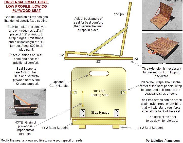
15 SEATING The suggested seating method is movable bench seats, as defined on this page. However, the builder can choose other types of seating, including fold up beach chairs, or a folding plywood seat. In the end, the seat type should be determined by the how the boat is to be used, and the comfort level required. I like a seat with a back, and will probably employ the bench seat for paddling or rowing, and a full seat for motoring. 1 x 2 Supports 16 Glue and screw the 1 x2 supports, on edge, to the underside of the seat, located as shown. It is important that the seat move easily in the boat, but not so loose that it can fall from the seat rails. Smooth all edges and round the corners. Finish with a waterproof paint. 1/2 Plywood Approx. 35 Round Corners Flush Bench Seat Rail Bulkhead 1 Cross Section Center Support The seat rail location should be such that when the seat is installed, it becomes flush to the top of the bulkhead center support. Mark the center of the rail location, and drill clearance screw holes, as shown. Glue and screw the rails in position. Allow to cure. BENCH SEAT 1 x 2 SEAT RAILS The seat material suggested is 1/2 plywood. However, if you will be seating 2 people on one seat, or are a heavier person, I suggest the use 3/4 plywood. Drawings are not to scale. Page 15


16 OPTIONAL SIMPLE MOTOR MOUNT 2x4 7" 5/8" Plywood 6" Approx. 11" 6 Simply fasten the mount securely to the motor, then just slip the mount tab into the hull slot. Easy to mount and remove. Fitted in Rear Hull Slot MOTOR MOUNT 1 x 2's Typical 1 x 2 Mount Assembly 6 x 3/4 Opening Optional Motor Mount Slot Cross Section, End View Mount Slot This is a sample photo from a different build, but it is representative of the assembly. Cross Section, Side View Page 16

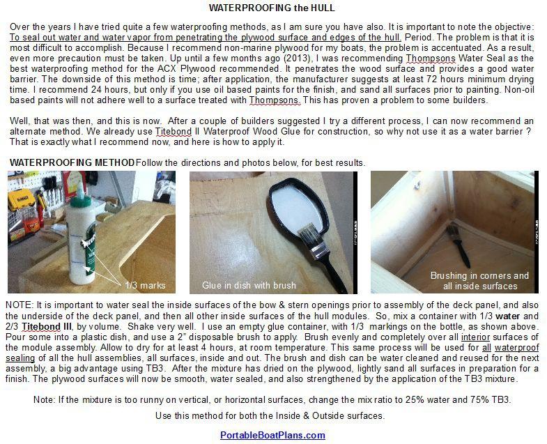
17 FINISHING The finishing of the boat is the most important element of boat building to some people. I believe it is equally important to the quality of construction. The next assembly step, the Tape & Glue Process, is proof of that statement. It is a seam sealing process that does not use epoxy, yet produces a tough waterproof barrier. After all T&G seams are complete, it is necessary to apply a waterproof sealer to the entire hull, inside and out. The choice of material is yours. I use Thompsons Water Seal on all my boats, but I also use only oil based finishes, like marine spar varnish or enamel paint. Thompsons and water based finishes (acrylic latex paint) do not work well together, as it does not allow the paint to dry properly. I even recommend coating the hull with a 25% watered-down mixture of TB3, mixed well, and brushed on in a thin penetrating waterproof coating. As I said, the choice is yours. Good luck with your project, and happy & safe boating! SPECIFICATIONS: OAL = 96 (8 feet) OAW = 36 (3 feet) OAH = 12 (1 foot) Weight = 50 pounds Capacity = 2 People or 450 pounds Build with basic handyman tools. Great starter boat for all ages. May max 3' wide Stacked (hinged) 26 max Folded for Transport FEATURES: Ultra-Stable Wide Design Simple Flat Side Construction Only 2 Sheets of 1/4 Plywood Adjustable Bench Seating for Two Row, Paddle or Trolling Motor Power Optional Foam Under Seats for Safety Hinged Hulls for Easy Transport and Setup Can be Constructed as a Single Hull Design a ken simpson design Page 17
18
19
20
21
22
23 ADDENDUM Center Of Radius METHOD FOR LAYING OUT A LARGE RADIUS To layout a large radius on a sheet of plywood, follow this simple process. First, notch a wood lead pencil as shown in the sketch below. Next, secure a length of non-stretch string, and knot it around the notch on the pencil. Place a mark on the floor (the flat surface you are working on) the length of the radius, in this case 5 feet. That is the center of the radius. Make sure it is perpendicular to the Panel. And mark the end locations of the Radius on the plywood. Now position the pencil at the lower end of the radius, in this case the bow bottom of the panel. You will now need a second person to place the other end of the string on the center of the radius, pull it taught, not tight. Now swing the pencil down toward the base of the panel. If the radius does not match, adjust the location of the center point slightly and try again. Once you have found the correct line, make the radius line on the panel dark. This will be the cut line. Use it as a template for the other panels. P E N C I L Approx. 5' Radius Bow SIDE PANEL 6 This is one method of developing a smooth radius. Another is to take a flexible length of wood, plastic or metal, and bend it between the start and finish points of the curve, Then trace the outline on the plywood. The important thing is that a smooth radius be developed, the actual dimensions of which are not important to the function of the boat. String Notch 24 Drawings are not to scale. Page 23
24 SPECIFICATIONS: OAL = 96 (8 feet) OAW = 36 (3 feet) OAH = 12 (1 foot) Weight = 50 pounds Capacity = 2 People or 450 pounds Build with basic handyman tools. Great starter boat for all ages. May max 3' wide Stacked (hinged) 26 max Folded for Transport FEATURES: Ultra-Stable Wide Design Simple Flat Side Construction Only 2 Sheets of 1/4 Plywood Adjustable Bench Seating for Two Row, Paddle or Trolling Motor Power Optional Foam Under Seats for Safety Hinged Hulls for Easy Transport and Setup Can be Constructed as a Single Hull Design a ken simpson design Page 24
25 Page 25
The U2-HULLZ Universal Utility Hulls
 A simple, practical, 2 module wedge hull design, that can be scaled to satisfy almost any small boating requirement, and easily modified to suite a builders unique needs. Universal Utility Hulls Drawn
CPB-1 Lightweight Folding Pram
 Lightweight Folding Pram An ultra-lightweight folding pram, only 15 pounds. Ideal for the lone fisherman or paddling enthusiast. Easy to make and fits in any vehicle when folded! See the hull and load
MODULAR PDRacer. A more portable version of the famous Puddle Duck Racer. Ken Simpson, Designer
 A more portable version of the famous Puddle Duck Racer. MARCH 2011 32 Pages After much deliberation, I have decided to provide a new version of the Puddle Duck Racer for those that have requested a more
TAPE & GLUE PROCESS Version: Jun. 2011
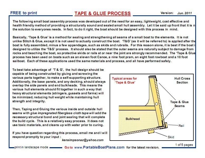
 FREE to print TAPE & GLUE PROCESS Version: Jun. 2011 The following small boat assembly process was developed out of the need for an easy, lightweight, cost effective and health friendly method of providing
A great weekend getaway vehicle for the lone sports man or woman. Print in Landscape mode, with 1/4 borders. Optional Enclosure or Full Canopy
 A great weekend getaway vehicle for the lone sports man or woman. Drawn 04-21-2013 Rev. 9-11-2016 ken simpson designs Print in Landscape mode, with 1/4 borders. This is the baby sister to the Mini CAMPER
How to build a Javelin Skiff
 How to build a Javelin Skiff This is not your grandfather s plywood boat! The Javelin involves a high-tech type construction, called composite. The hull can be constructed with foam or plywood; these materials
Cowper From Steve Wolverton on the T&TTT forum, Feb 2005 For Reference Only Do not use to build a trailer. Check on Teardrop and Tiny Travel Trailers
 Cowper From Steve Wolverton on the T&TTT forum, Feb 2005 For Reference Only Do not use to build a trailer. Check on Teardrop and Tiny Travel Trailers for up to date building information; http://www.mikenchell.com/forums
Tools and Tips: ( 1 )
") Tools and Tips: As you build instructions will show in my many picture manual how to assemble. You can use your own methods as you desire, my results are very good. A smooth, flat work surface is very
Tools and Tips: As you build instructions will show in my many picture manual how to assemble. You can use your own methods as you desire, my results are very good. A smooth, flat work surface is very
CUSTOM SHUTTERS IN-A-BOX
 CUSTOM SHUTTERS IN-A-BOX SHUTTER ASSEMBLE INSTRUCTIONS & INSTALLATION INSTRUCTIONS 1. Inspect the contents of your package. Do not discard the shutter packaging box until you have started painting your
Balustrade Systems / Installation Instructions
 A. PARTS AND SUPPLIES NEEDED FOR INSTALLATION Hardware included for each 10 section of rail: 2 3 x 1-1/2 L-brackets 4 1-3/4 x 3/16 Blue hex-head screws for anchoring the L-brackets to the newel cap, column
Continue gluing the remaining top parts ensuring the angled piece is glued well. Set aside and let dry. See photo below
 Radiator rev 1.1 The SE5a s radiator is one of the most recognized radiators in WW1. It is one of the components that defines the SE5a. The original SE5a has seen multiple radiator designs used during
Dura-Lock Roof System
 DLR-14 Dura-Lock Roof System Assembly and Installation Instructions Read the instructions before starting the job. They explain the steps required to produce a finished product that will meet factory specifications.
ADULT. Adirondack / Muskoka Chair Plans
 ADULT Adirondack / Muskoka Chair Plans Materials List 3/4" x 9 1/2" (1.9cm x 24.1cm) redwood, cedar or pine boards. Six, 8' (2.44m) boards should make one chair depending on knots and layout. You can also
Grade 11 Woods Lift Lid Coffee Table. Based on Under the big Top from Popular Mechanics Website
 Grade 11 Woods Lift Lid Coffee Table Based on Under the big Top from Popular Mechanics Website TABLE TOP 1. Select enough lumber to construct a top that is between 22 ½ and 24 wide after jointing. Ensure
BUILDING A STORM DOOR
 BUILDING A STORM DOOR BY NEAL BARRETT Illustrations by George Retseck If you're in the market for a storm door, you probably know that there are many styles and models available. However, most of them
Instructables Butcher Block Top
 Instructables Butcher Block Top Project Overview: This project requires basic woodworking skills and access to woodworking machines. Woodworking machines have sharp cutting edges and are NOT forgiving.
Tools and Tips: ( 1 )
") Tools and Tips: As you build instructions will show in my many picture manual how to assemble. You can use your own methods as you desire, my results are very good. A smooth, flat work surface is very
Tools and Tips: As you build instructions will show in my many picture manual how to assemble. You can use your own methods as you desire, my results are very good. A smooth, flat work surface is very
The image above is intended to give you an idea of what the dovecote will look like when finished.
 Thank you for buying my book, I hope it is useful and enjoyable in your quest to building your own dovecote. This book will give you step-by step instructions on how to build your own dovecote also included
Project Skill Level: INTERMEDIATE Plywood Used: CANPLY EXTERIOR Good Two Sides (G2S) or precision sanded Aspen
 or precision sanded Aspen") Project Skill Level: INTERMEDIATE Plywood Used: CANPLY EXTERIOR Good Two Sides (G2S) or precision sanded Aspen MATERIALS LIST: (1) ¾" x 4 ft x 8 ft plywood panel (20) #8 x 2" Robertson or Phillips wood
Project Skill Level: INTERMEDIATE Plywood Used: CANPLY EXTERIOR Good Two Sides (G2S) or precision sanded Aspen MATERIALS LIST: (1) ¾" x 4 ft x 8 ft plywood panel (20) #8 x 2" Robertson or Phillips wood
Beds may be put up or taken down quickly by use of a simple bolted connection at rails and uprights. MATERIALS LIST
 CANPLY This design has been made both functional and attractive by use of pattern cut-outs in head and foot uprights, which serve as ladders. Since most children love to climb, getting them to bed will
More Storage Space Under Yacht Bed
 More Storage Space Under Yacht Bed Open up storage space under your bed! Convert your bed deck to a Lifting Hatch with Gas Spring assist! Many bed decks on boats and RV s have two or three pieces of plywood
woodworkersjournal.com MATERIAL LIST
 MATERIAL LIST T x W x L 1 Legs (2) 1 1 2" x 3 1 2" x 36 7 16" 2 End Uprights (2) 1 1 2" x 3 1 2" x 32 1 2" 3 Stringers (4) 1 1 2" x 3 1 2" x 42" 4 Top Cladding, Long (2) 3/4" x 7 1 4" x 65 3 4" 5 Side
Motorcycle Lift Assembly Instructions
 Motorcycle Lift Assembly Instructions Copyright JCS 2009 Rev1M Page 1 Lift Table Assembly Instructions The following pages will assist you in the construction of your Motorcycle Lift Table. You will find
Pivot-Door Downdraft Cabinet Plans
 Pivot-Door Downdraft Cabinet Plans Finished Cabinet Closed Open Exploded View Introduction This simple downdraft-style dust collection cabinet is a great way to keep your shop cleaner and keep your router
FUSELAGE CONSTRUCTION
 FUSELAGE CONSTRUCTION Note: prior to building and gluing on the work surface use protective covering on your building surface. (wax paper or clear wrap) Fit the laser cut Fuselage Front and Fuselage Rear
Copyright 2010 Springbok Publishing All Rights Reserved- Page 1
 Copyright 2010 Springbok Publishing All Rights Reserved- www.woodensaddlerackplans.com Page 1 Legal Information All contents copyright 2010 by Springbok Publishing. All rights reserved. No part of this
Cardboard Cup Regatta Plans and Directions
 To help celebrate the upcoming Crystal Lake America s Cardboard Cup Regatta, we have asked a veteran of 18 races to submit a set of plans and directions to build an unsinkable and competitive cardboard
Chapter 23. Garage Construction
 Chapter 23. Garage Construction 23.1 ESTABLISHING CHALK LINES 23.2 MEASURING AND CUTTING WALL PLATES 23.3 MARKING WINDOW & DOOR LOCATIONS ON EXTERIOR WALL PLATES 23.4 MARKING STUDS ON EXTERIOR WALL PLATES
Installation Instructions
 www.marlite.com Effective Date 03/01/2018 ARTIZAN FRP, SYMMETRIX FRP, ENVUE FRP, STANDARD FRP Installation Instructions Statements expressed in this technical bulletin are recommendations for the application
Above are the offsets for the plywood panels.
 DinkyDink Plans Bottom Panel Half Station X Y X2 Y2 1 1/4 3/4 0 11 5/16 2 4 9/16 4 12 9/16 3 11 11/16 1/4 11 7/16 14 1/2 4 18 5/8 1/16 18 5/8 15 11/16 5 25 3/4 0 25 3/4 16 5/16 6 32 13/16 0 32 13/16 16
Fan Back Adirondack Chair Assembly Instructions How To Assemble Your Chair in 12 Easy Steps Parts List 5 9
 Fan Back How To Assemble Your Chair in 12 Easy Steps Parts List 5 9 5 5 9 5 5 1 12 11 7 7 1 8 13 10 2 6 4 3 3 3 3 3 2 #1 (2) frame, left & right #2 (2) 20" legs, left & right #3 (6) 20" seat slats #4 (1)
Installation Instructions for. Before You Begin TOOLS REQUIRED
 Composite Railing System STEP-BY-STEP Installation Instructions for Spectrum Composite Railing Virtually maintenance free 20-year warranty EverNew Spectrum Railing system is designed to work with a number
Metal Aircraft Landing Light Installation Instructions
 Metal Aircraft Landing Light Installation Instructions This landing light kit was designed for the Thorp T-18 as a method of installing a halogen landing light in the leading edge of the outer bay of the
Hatch Installation For Pygmy Solo and Double Kayaks
 Introduction/Overview Hatch Installation For Pygmy Solo and Double Kayaks The hatch kit consists of several wooden lips, strapping and hardware. The hatch is constructed by cutting a hole in your deck,
Nanton Grain Mill Assembly
 ( 1 ) Nanton Grain Mill Assembly Locate package for assembling storage building. These are cut from 1/8 masonite. Inspect and lightly sand edges where it will be bonded. Use white glue or CA glue to bond.
Photo Essay How to Build an. Alaskan. Grand Banks Dory. Plans for this boat may be found at:
 Photo Essay How to Build an Alaskan Grand Banks Dory Plans for this boat may be found at: http://www.spirainternational.com/ How to Build an Alaskan Grand Banks Dory The Alaskan is an easy to build Spira
15 Dovetail Jig. Instruction Manual. Part # 3452
 15 Dovetail Jig Instruction Manual Part # 3452 CAUTION: Please read, understand, and follow all manufacturers instructions, guidelines and owners manuals that come with your power tools. Peachtree Woodworking
The Park Hotel Instructions for Assembly
 The Park Hotel Instructions for Assembly Kit Contents: 280 ea. Laser Cut Acrylic Parts. 1 ea. 6" Plastic Coated Wire. 5 ea. Sidewalk Parts. 14 ea. Cast Resin Dormers. 12 ea. Window Glass Templates, 12
Chapter 1. Beam and Sill Plates
 Chapter 1. Beam and Sill Plates 1.1 ESTABLISHING SQUARE SILL PLATE CHALK LINES 1.2 INSTALLING TREATED SILL PLATES 1.3 INSTALLING LAMINATE BEAM Tools needed by volunteers: Hammer Nail apron Tape measure
136 PLYWOOD DESK 522
 136 PLYWOOD DESK 522 Simple in design and inexpensive, this plywood desk is made from a single 4- x 8-foot panel. Plywood is available with many hardwood veneers; it can also be covered with plastic laminate,
END FRAMES. End frames built using pressure treated 2x4 (1 1/2" x 3 1/2") 36" 34" 7/16" pilot hole. 5 1/2" x 1/2" lag bolt 8" wheel 23"
 36 34 7/16 pilot hole. 5 1/2 x 1/2 lag bolt 8 wheel 23") END FRAMES End frames built using pressure treated 2x4 (1 1/2" x 3 1/2") 23" 17 1/2" (B) (B) Measure from the bottom of your stone to 1" below the lip to get your measurement. 17 1/2"(B) 36" 34" 1/2" flat
END FRAMES End frames built using pressure treated 2x4 (1 1/2" x 3 1/2") 23" 17 1/2" (B) (B) Measure from the bottom of your stone to 1" below the lip to get your measurement. 17 1/2"(B) 36" 34" 1/2" flat
PoorBoy Skiff. A 10-11ft 6in skiff for outboard motoring By Steven Lewis
 PoorBoy Skiff. A 10-11ft 6in skiff for outboard motoring By Steven Lewis PoorBoy is about the simplest small motorboat you will come across. It consists of 2-2 1/4 sheets of plywood (1-1 1/4 sheets x3/8
Wood Duck Nest Box Design & Assembly Directions
 Wood Duck Nest Box Design & Assembly Directions Instructions, Illustrations & Photos Courtesy of MWDI and Scott Jasion, Harford County Chapter, Ducks Unlimited Side door opening design for easy mounting
Installation Guide. Pionite Decorative Surfaces One Pionite Road, Auburn, Maine PIONITE ( )
") Installation Guide A Subsidiary of Panolam Surface Systems SMPBRO00-012 6/14 Pionite decorative laminates are designed for finished interior surfaces which require high impact, wear and stain resistance
Installation Guide A Subsidiary of Panolam Surface Systems SMPBRO00-012 6/14 Pionite decorative laminates are designed for finished interior surfaces which require high impact, wear and stain resistance
WPS crew Doors Installation instructions
 WPS-132-133 crew Doors Installation instructions ORDER OF INSTALLATION FOR A COMPLETE ENCLOSURE OF A CREW WPS (Weather Protection System) IS AS FOLLOWS: 1. Heater 2. Rear Thresholds - Right Hand & Left
SE5a Wing Panels rev 1.0
 SE5a Wing Panels rev 1.0 The top and bottom wings are different. They might look the same but the bottom wing has one less rib and some rib spacing difference. This is due to where the wooden interplane
SGTalon s Enterprise-A Foamie Build Guide. SGTalon s. Enterprise. Enterprise--A. Assembly Instructions
 SGTalon s Enterprise SGTalon s Enterprise--A Enterprise Assembly Instructions Page 1 4-13-2013 SGTalon s Enterprise *******Recommended Hardware******** 2.6oz 250w Motor and Speed Control with 8x6 prop
GENERAL NOTES: Page 1 of 9
 Laminating A Zia Into A Turning Blank by W. H. Kloepping, Jan. 2009 This describes how a zia (the New Mexico state symbol) can be laminated into a turning blank. Materials needed: Square Turning Block
The Park Hotel Instructions for Assembly of N Scale Kit
 The Park Hotel Instructions for Assembly of N Scale Kit Kit Contents: 198 ea. Laser Cut Acrylic Parts, 2 ea. Chimney Parts Sheets, 1 ea.2".040 styrene rod, 5 ea. Sidewalk Parts, 14 ea. Cast Resin Dormers,
Why are we giving this guidebook as a FREE download?
 Construction Guide Queen, Double & Twin Vertical 1 Note: This guide covers the construction steps for all 3 sizes of the vertical wall mount Easy DIY Murphy beds, Queen, Double and Twin. The construction
Fokker Dr1 Master Instructions
 Fokker Dr1 Master Instructions Rev 1 Congratulations on your new project. This Dr1 kit is the finest to date. The construction of the plane is similar and exactly like the original. Take your time and
Front Vise 70G G08.02
 Front Vise 70G08.01 70G08.02 The following instructions guide you through the installation of either the Regular Front Vise (70G08.01) or the Large Front Vise (70G08.02). The first step is to determine
10. Wing prep and subassembly
 Date Section Objective: Construct and fabricate the sub-assemblies of the wing panel. Required Parts: Wing left 11gal PN104-300, Wing right 1gal PN104-400, Wing left 15 gal option PN104-322, Wing right
ULTIMATE ROUTER TABLE PLANS. By Dan Phalen
 ULTIMATE ROUTER TABLE PLANS By Dan Phalen January 2017 Ultimate Router Table Plans. Copyright 2012-2017 by Daniel Phalen. Published by Creston Hall Publishing Company. All rights reserved. No part of this
Silverware Chest Plan
 Silverware Chest Plan 05L14.01 Introduction 1. Measure the space required for your cutlery before beginning this project to be sure that it will fit in the drawers and top compartment. The best way to
Frameless Inline Door With Return QCI5263
 INSTALLATION INSTRUCTIONS Frameless Inline Door With Return QCI5263 WALL MOUNT HINGES FRAMELESS DOOR / PANEL / RETURN PANEL QCI5263 REV. 0 Page 1 Certified 06/17/2016 Parts List with wall mount hinges
Building Tips This model can be built using the following types of adhesives:
 Page 1 Building Tips This model can be built using the following types of adhesives: Epoxy (with or without microballons) Odorless cyanoacrylate (CA) with accelerator UHU Creativ for Styrofoam (or UHU
A Skin-on-Frame Pram. Designed by Dana Munkelt. Drawings by Andrew Walters. Duckworks Boatbuilder's Supply duckworksbbs.com
 A Skin-on-Frame Pram Designed by Dana Munkelt Drawings by Andrew Walters Duckworks Boatbuilder's Supply duckworksbbs.com "" is a small skin-on-frame (SOF) pram design with a twist; a solid plywood floor.
Balustrade System Installation - Cambridge & Huntington
 A. PARTS AND SUPPLIES NEEDED FOR INSTALLATION Hardware included for each 10 section of rail: 2 3 x 1-1/2 L-brackets 4 1-3/4 x 3/16 Blue hex-head screws for anchoring the L-brackets to the newel cap, column
STANDARD CANOPY WORK REPORT B-1
 STANDARD CANOPY WORK REPORT B-1 No. Check Parts / Tools Qty _ Canopy Lock 1 [ ] 6E2-3 Canopy Hinge Block 1 2 [ ] 6E4-5 Canopy Side Frame 2 2 [ ] 6E2-1 Canopy Lock Assembly 1L + 1R 3 [ ] 6E2-4 Rear Lock
Hinge Mortising Jig. One of the make it or break it parts of building a. 6 ShopNotes No. 74
 Hinge Mortising Jig A Mortise for a Hinge. Quick, clean, and accurate that s the only way to describe the mortise you get with a trim router and this hinge mortising jig. One of the make it or break it
Copyright 1998 KDE Technologies
 Modular Computer Corner Desk Unit Copyright 1998 KDE Technologies http://members.tripod.com/~kdetech/ 1. Introduction 2. Plans Sheet one - Isometric Sheet two - Top Detail / Corner Unit Sheet three - Leg
Kentucky 4H Wood Science Plans Notebook. Plans Level 3
 Kentucky 4H Wood Science Plans Notebook Plans Level 3 MATERIALS: 2 pieces wood 3/4 x 10 x 4 1 piece wood 3/4 x 12 x 4 2 pieces wood 3/4 x 3 x 2 5 1/2" 2 pieces wood 3/4 x 3 x 1 8 1 piece wood 2 x 4 x
Plans. Easy-to-Build Full-size Deluxe Murphy Bed Plan. For more plans, tools and hardware visit rockler.com
 Easy-to-Build Full-size Deluxe Murphy Bed Plan Build a full-size Deluxe Murphy Bed complete with decorative molding and matching side cabinets! Plans For more plans, tools and hardware visit rockler.com
Important Note: Why this guidebook is FREE?
 Easy DIY Murphy Bed Construction Guide 1 Important Note: This guide is a FREE SAMPLE of our Complete Construction Guidebook. With the help of this guide you will get familiar with the construction steps
Building instructions ARTEMIS Sailing Canoe Day Five Version 1.0 Brian Pearson & Dr. Axel Schmid Day Five. Assembly of Planks and Frames
 Building instructions ARTEMIS Sailing Canoe Version 1.0 Brian Pearson & Dr. Axel Schmid 2016 Assembly of Planks and Frames Steps: Assembling hull plansk with wire Install frames Align and check keel rocker
Router Table. Construction
 Router Table A router table is an invaluable tool. The problem, however, is that ready-built router tables are usually relatively expensive and too narrow for many projects. This router table provides
Real Good Toys 10 Quarry St Barre, VT
 Real Good Toys Special Edition Kit #SE-RR 29 /5 Congratulations on your choice of a Real Good Toys product. Your kit has been precision made with meticulous care by our craftspeople using carefully selected
FORWARD FUSELAGE SIDES & REAR TOP SKINS
 FORWARD FUSELAGE SIDES & REAR TOP SKINS WORK REPORT Step No. Check Parts / Tools Qty Preparations. 1 [ ] 6F5-3 Upper Front Longerons 2 2 [ ] 6F5-5 Heel Support 1 3 [ ] 6F5-2 Front Floor Skin 1 3 [ ] Firewall
Building Instructions Diva cabin boat
 Building Instructions Diva cabin boat Order no. 3093/00 aero-naut Modellbau Stuttgarterstr. 18-22 D-72766 Reutlingen / Germany http://www.aero-naut.com 1 For pictured building instructions please see the
SUGAR CREEK HOTEL PHOTO REAL BUILD KIT
 SUGAR CREEK HOTEL PHOTO REAL BUILD KIT by Innovative Hobby Supply INSTRUCTIONS FOR: Kit BK 6407 Sugar Creek Hotel Build Kit ~ S scale Free replacement parts are available simply by calling 866 712 4059.
Slicing Jig For Pen Inlays
 Slicing Jig For Pen Inlays By Randall Smith (randyrls) May 2008 This article has been downloaded from the library of the International Association of Penturners. www.penturners.org You are welcome to reproduce
Max Launch Abort System Prod. No *Kevlar is a registered trademark of Dupont
 Flying Model Parts List Max Launch Abort System Prod. No. 3014 A 11820 - Body Tube 3.5 Diam x 5.5" Long B 11824 - Orange Capsule Base Shoulder Ring C 16032 - Laser-cut Ring motor mount rear D 16033 - Laser-cut
Low/High Tunnel Greenhouse Plans
 Low/High Tunnel Greenhouse Plans Tools Needed (See the complete list of Greenhouse Tools) Hacksaw or Reciprocating Saw Socket Wrench, Adjustable Wrench or Nut Drivers Electric Drill with Drill Bits Sledge
Bateau.com PH18 CNC kit notes 1/5
 Bateau.com PH18 CNC kit notes 1/5 These building notes must be used in conjunction with the standard building notes included in the plans package for this boat. The PH18 kit is assembled as described in
Building an Unfeathered Paddle with a Wood Shaft and Carbon Fiber Blades
 Building an Unfeathered Paddle with a Wood Shaft and Carbon Fiber Blades by Duane Strosaker Choosing the Wood Two 3/4" pieces of Sitka spruce laminated with epoxy for an unfeathered one-piece paddle. For
Building Instructions ARTEMIS Sailing Canoe Day Six Version 1.0 Brian Pearson & Dr. Axel Schmid Day Six. Align and Glue Planks
 Version 1.0 Brian Pearson & Dr. Axel Schmid 2016 Align and Glue Planks Steps: Align boat, check dimensions Join planks provisionally Pull wires Glue the outside planks Tools and Materials: Epoxy putty
Lumber Smith. Assembly Manual. If you are having problems assembling the saw and need assistance, please contact us at:
 Lumber Smith Assembly Manual If you are having problems assembling the saw and need assistance, please contact us at: 804-577-7398 info@lumbersmith.com 1 Step 1 Safety Carefully read the Owners Manual.
Redwood strips are tacked to the templates, and edge-glued. Drive brads through into the templates before putting on fiberglass doth.
 1 Make the building form and attach templates to the crosspieces. Nail a strip down the center to hold the stems and templates in position. prototype canoe took about three weekends to build. She's broad
Big Oz. Rocket. User Guide V0313
 Big Oz Rocket User Guide 59824 V0313 Materials Included The Big Oz Rocket Kit should include the following materials. If something is missing, contact Customer Service at 800-358-4983. 20-ounce plastic
Treviso POCKET BILLIARD TABLE INSTALLATION MANUAL. SERVICE DEPARTMENT P.O. BOX 68 BRISTOL, WI 53104
 Treviso TM POCKET BILLIARD TABLE INSTALLATION MANUAL www.brunswickbilliards.com SERVICE DEPARTMENT P.O. BOX 68 BRISTOL, WI 53104 51-905881-000 NOVEMBER 2008 NOTE: Please use the instructions in this manual
Photo Essay Building a. Key Largo. Carolina Dory. Plans for this boat may be found at:
 Photo Essay Building a Key Largo Carolina Dory Plans for this boat may be found at: http://spirainternational.com/ Photo Essay Building a Key Largo Carolina Dory The Carolina Dory is a specialized type
 America s leading woodworking authority To download these plans, you will need Adobe Reader installed on your computer. If you want to get a free copy, visit: http://adobe.com/ reader. Having trouble downloading
Empire Dresser Plans
 1 Empire Dresser Plans Materials 1 sheet 3/4" plywood (cabinet grade 4' x 8') 1 sheet 5 mm (3/16") underlayment plywood 4'x 8', buy another 1/2 sheet if you want to put a back on the dresser. 1-2" x 4"
PORTA TRAK OWNERS MANUAL
 PORTA TRAK OWNERS MANUAL Table of Contents: I. Rail and Frame Parts List Please read the instructions thoroughly before setting up the Porta Trak. Carefully follow how to spring the bed step by step. II.
Piper Cherokee /3 scale. Construction Manual
 Piper Cherokee 140 1/3 scale Construction Manual STAB CONSTRUCTION 1. Remove foam cores from cradle and place on flat surface. Inspect pieces before you epoxy halves together making sure leading and trailing
PRIVACY FENCE WITH LATTICE INSTALLATION INSTRUCTIONS
 PRIVACY FENCE WITH LATTICE INSTALLATION INSTRUCTIONS These instructions are to be used as general guidelines for the installation of your vinyl fence under normal installation conditions. Local conditions
Bates 1/8 scale B-26. Parts List. Instructions
 Bates 1/8 scale B-26 Vacuform Pieces Swivel Ball 1 Cockpit Floor 1 Ball 2 Cockpit Back Wall 2 Two Flanges 3 Dash 3 Seven 0-64 x 1/4 Bolts 4 Dash Hood 4 Seven 0-64 Nuts 5 Center Console 6 Pilot Seat Fire
Build your own Drawer unit. D3 / D4
 Page1 Build your own Drawer unit. D3 / D4 1: Introduction. This guide will give you the plans, materials and how to information to build your own drawer unit. The dimensions given will fit a D3 or D4,
Chapter Four, Fitting out the Shell
 Chapter Four Fitting out the Shell This chapter outlines the process for fitting the parts that go into a round or stave back shell. Square back sound boxes usually have the cap and base of the sound box
SE5a Instrument Board part 2 - rev 1.1
 SE5a Instrument Board part 2 - rev 1.1 Fuel (Petrol) Valve This valve uses two circular name plates, eight brass screws, one black plastic base, copper wire and two black plastic risers. You can pick any
Project Plans Kreg Tool Company/BuildSomething. All Rights Reserved.
 BY Project Plans ONE-OF-A-KIND CUTTING BOARD This solid-maple cutting board offers ample space for cutting and a comfortable handle, but the most-unique feature lies underneath. A cutout in the lower layer
Building Instructions
 Building Instructions Tools Required Tape measure Straight edge Pencil/pen Jigsaw Table Saw Circular Saw Electric drill 1 Hole saw bit Saw horses/table Protractor Staple gun Caulk gun Paint brush Wrenches
Installing your new Bevella Top. L Shaped Countertop with Joints No Finished Ends (Fits Between Four Walls)
") Installing your new Bevella Top L Shaped Countertop with Joints No Finished Ends (Fits Between Four Walls) Bevella RTI Countertops are engineered and manufactured to the highest quality standards, built
Installing your new Bevella Top L Shaped Countertop with Joints No Finished Ends (Fits Between Four Walls) Bevella RTI Countertops are engineered and manufactured to the highest quality standards, built
After printing these plans, several pages will need to be taped together to form a larger plan. Below is a diagram of which pages need assembled.
 Watermill Building Plans For complete building instructions and instructional videos, please visit the main web site at www.hirstarts.com/watermill/watermill.html. Using these plans alone will not give
GE Monogram. Installation. Instructions. Microwave Oven. Under Cabinet Installation. and. JX827 Series Built-In Kit. Models.
 GE Monogram Installation Instructions Under Cabinet Installation and JX827 Series Built-In Kit Models ZEM200 Series CAUTION WARNING Before you begin Read these instructions completely and carefully. IMPORTANT:
Cobra X Q Construction Tips Construction: Bel y pan
 Cobra X Q Construction Tips : The white plastic in this kit is high impact styrene. It can be painted with most types of coatings if light coats are applied this is necessary due to the thickness of the
RFS Class II Rocket Assembly Instructions
 RFS Class II Rocket Assembly Instructions Instructions by: Loc Precision Photos by: Great Lakes Space Port Sheboygan Education Foundation, Inc. Welcome and thank you for joining the Rockets for Schools
HOUSE PARTS PACKED IN HOUSE BOX PARTS IN PLASTIC BAG (HARDWARE) PARTS IN SMALL PLASTIC BAG (FLOOR CLIPS) PARTS PACKED IN BUNDLE
 PARTS IN SMALL PLASTIC BAG (FLOOR CLIPS) PARTS PACKED IN BUNDLE") Check parts against this list before starting assembly. Refer to illustrations on pages 6 and 7 to view house parts. If any shortages are found, refer to Packing Slip for claim instructions. Item 3 5 6
Check parts against this list before starting assembly. Refer to illustrations on pages 6 and 7 to view house parts. If any shortages are found, refer to Packing Slip for claim instructions. Item 3 5 6
The Midtown Apartment Building
 The Midtown Apartment Building Instructions for Assembly of The Midtown Apartment Building. Kit Contents: 70 each laser cut acrylic parts. 3 each sidewalk parts. 3each Window Glass Templates, 3 each Window