A great weekend getaway vehicle for the lone sports man or woman. Print in Landscape mode, with 1/4 borders. Optional Enclosure or Full Canopy
|
|
|
- Philomena Golden
- 6 years ago
- Views:
Transcription
1 A great weekend getaway vehicle for the lone sports man or woman. Drawn Rev ken simpson designs Print in Landscape mode, with 1/4 borders. This is the baby sister to the Mini CAMPER CRUISER Note: A 2 occupant sleeper version is shown on page 34. This was developed for those that do not have a large vehicle to transport an overnight craft. This version of MCC will fit in all Trucks, SUV's, as well as many Cars and Hatchbacks, and on most Trailers. The Designer fits it in his PT Cruiser. This Micro CC version is also limited to one occupant for overnight sleeping, but will support two occupants for boating, up to a load of about 375 pounds. The design goals were for an ample beam, and freeboard, easy to build, and propulsion by Paddle, Oars, Trolling Motor or 2.5 HP small lightweight outboard motor. The boat is stand-up stable. Overall Length = 96 inches max. Overall Width = 37 inches max. Overall Height = 25 inches max. Hull Empty Weight = 75 pounds Capacity = 360 pounds max. Hull Speed = 5 mph Approx. cost to build = $225 Does not include finishes. Cross Section Movable Bench Seats Optional Enclosure or Full Canopy Basic Tarp Cover Builder options are encouraged. Great for hunting, fishing or just leisurely boating! A modified 2 thin high density foam mattress is suggested for sleeping comfort and convenience. Alternate Method of Transport A Sailboat option is shown on page max Nested Modules Nested Size = 48 L x 37 W x 28 H max. A Craig Titmus original design Nested Modules Video: Page 1 of 64 T hi s i s a n e xp e rim e n ta l d e si g n dra wn u p by a n u ntra in e d a m ate u r. T h e De si g ne r a cce p ts no l i ab i l i ty for a ny lo ss o r da m ag e susta i n ed d uri n g con stru cti o n o r u se. Bu i l d ers m ay use th e se p l an s to con stru ct a sm a l l b o ats fo r th e i r o wn use. Co m m ercia l m a n u fa ctu re rs m u st ask th e De si g n er to n e g o ti a te p erm i ssi o n.
2 General Notes The idea for the is the designers desire for a portable overnight boat that fits in his car. It includes an ample beam and freeboard, generous volume, seating for two, and safety buoyancy. It is sturdy, easy to build, quite portable and utilizes a standard trolling or small gas motor. To have strength and yet be lightweight, the plans use some non-traditional methods of assembly, specifically the Tape & Glue construction process developed and incorporated by the designer. This provides a durable, yet truly portable, finished boat, and the building process is easily mastered by the home handyman and amateur boat builder. As a result, only hand tools, a jig-saw, a power drill and a large carpenters square, scissors, and tape measure are all that will be required throughout the assembly process. Be selective in your choice of materials. Use plywood that is preferably exterior rated. Marine Plywood is very expensive, so the use of ACX Grade is recommended, but be choosy. It is important to note, the final choice of materials is the decision of the builder. We have made specific recommendations, but if the builder has previous experience with different methods and materials, that is their choice, and we respect that decision. Certainly, minor changes in design are encouraged, to provide a 'custom' boat to satisfy a builders specific needs. We do not make changes to the drawings. This would be up to the individual builder, and their responsibility. Also, it is very important that none of the basic design parameters be drastically modified, as this may adversely affect overall boat safety or performance. Seating choice is also up to the builder. Bench seats are shown, but folding seats are also suggested. It should also be noted that the hull modules can be glued and screwed together, for those that do not have limitations of storage or transportation. The hull can be constructed using 1/4 plywood, for greater durability, or the exterior could also be fiberglassed, allowing yet thinner and lighter (4 mm) plywood hull building material. Any questions or comments regarding the construction and/or design of this project will be responded to in a timely fashion. Thank you for your interest, and for purchasing these plans, and good luck with your special project. Please Note: All drawings are done free hand, and as such, some irregularities may occur. And don t forget to visit for new designs and updates. Happy Boating! Ken Simpson, Designer 2
3 Suggested Front Window Front 27 DESIGN LAYOUT 24 Cabin Opening OAL = 96 max OAW = 37 max OAH = 26 max Weight = 75# Capacity = 360# View 36 Rear View Special Note: The Forward and Rear modules are built exactly the same. Nested: 48 L x 36 W x 28 H Optional Hinge 32 Optional Hull Shape Straight Sides Note: Motor mounting is not fully defined. It is up to the builder to select the propulsion type, and it's mounting method. Nested Modules Nesting location for 23 optional Center Module. See page 28 Optional Custom Fold Down Cockpit and Cabin Enclosure Basic Tarp Cover Second Occupant Optional Portholes 24 Human figures shown are 6 feet tall. Optional Removable Aft Enclosure (Store in front module) Sleeping Position See page 32 for a dual sleeper version! Side Mounted Motor 24 Optional Raised Transom pounds pounds Optional Bow Shape 15 radius 80 + Water Line Sealed Compartment 7-1/2 Side Battery Location 12 Optional Transom 3
4 HULL PANEL DIMENSIONS ALL 5 MM PLYWOOD 12 9 Photo assembly at end of plans. Optional Bow Shape, 15 radius Cabin Side Panels (2) 48 L x 12 H Optional 8 Port Bow Entry Side Panels (4) 48 L x 12 H 1-1/2 8 8 x 4 Assembly Supports 4 Required 9 See modified rear panels below /2 Base Panels (2) Approx. 40 L x 32 W Fit at Assy. Fit at Assy. means to measure the length & width of the sub-assembly, then mark & cut the matching panel to fit exactly. Small Radius Optional Cabin Bow Panel 14-1/2 H x 35 W Bulkheads (2) 11-7/8 H x 35 W Fit at Assy. Optional Hull Shape Straight Sides 26-1/ Lower Bow & Transom Panels (2) 14-1/2 H x 35 W Cabin Bulkhead 13 H x 35 W 1-1/2 x 3' long These 2 caps made from 1 x 2 lumber, or 1 x 3 lumber for greater strength. Note: Transom could be made from ½ inch plywood for greater strength. OPTIONAL Print only the pages you actually need to build the project! 13 Cut out at final Cabin assembly 32 End Cap (2) 11-7/8 32 Fit at Assy. Top Cap 30 x 28 5 MM Ply See page 6, sheet 4 7-1/2 8 degree sides 35 Rear Side Panels (2) Modified Transom Truck, big SUV, or Trailer Transport 48 L x 12 H 3 The hull 'straight side' option, above, and 'bow shape' is for builders who are not restricted by transport vehicle size opening, and it will increase buoyancy by about 50 pounds. Drawings Not To Scale 4
5 Fit at Assy. Front Base Panel Approx. 40 L x 33 W Fit at Assy. Fit at Assy. means to measure the length & width of the sub-assembly, then mark & cut the matching panel to fit exactly. ACX Grade or better Plywood Primary Grain Bulkhead 11-7/8 H x 35 W 5 MM Plywood ¼ Plywood is suggested if you want a more robust, but heavier, assembly. Cut 48 here at Lumber Yard If you cannot transport an 8' plywood sheet. Otherwise, make these your first cuts at home. Bulkhead 11-7/8 H x 35 W NOTE: If you elect to use the straight side option, you will have to increase the width of these base panels Note that all panels necessary to build one module are on this sheet of plywood. Micro CAMPER CRUISER Rear Side Panel 48 L x 12 H Bow Panel Approx. 14-1/2 H x 35 W 8 x 5 Assembly Supports Optional Bow Shape Sheet 2 PLYWOOD LAYOUT Rear Side Panel 48 L x 12 H Round Bow Option Front Side Panel 48 L x 12 H 48 Front Side Panel 48 L x 12 H Sheet 1 If you do cut the plywood sheet in half, make sure you lay out the panels with the plywood grain as shown. Builder Optional Features Note that all panels to build one module are on this sheet of plywood. Rear Base Panel Approx. 40 L x 33 W Fit at Assy. Plywood Primary Grain Transom Panel 14-1/2 H x 35 W
6 Cabin Bow Panel Approx. 14-1/2 H x 35 W Optional 8 Port Cabin Side Panels 48 L x 12 H 48 Cabin Side Panels 48 L x 12 H Optional 8 Port nd Inner Base Panel, 2 Layer Approx. 39 L x 32 W nd Notice the 2 layer is cross grain to the first layer. Fit at Assy. Sheet 4 PLYWOOD LAYOUT Plywood Primary Grain Micro CAMPER CRUISER Inner Base Panel, 2nd Layer Approx. 39 L x 32 W 5 MM Plywood Notice the 2nd layer is cross grain to the first layer. ACX Grade or better ¼ Plywood is suggested if you want a more robust, but heavier, assembly. Cut here at Lumber Yard If you cannot transport an 8' plywood sheet. Otherwise, make these your first cuts at home. If you do cut the plywood sheet in half, make sure you lay out the panels with the plywood grain as shown. Drawings Not To Scale Fit at Assy. Note: The residual plywood will be used on top of side rails and the cabin top for a finished appearance. Also used for buoyancy cell tops and sides. See page 27. Top Cap 30L x 27 W Fit at Assy. Optional Radius 24 Mini B.O.M. 4-sheets of 5 MM ACX Ply 96 oz. of TB3 wood glue (6-16 oz. bottles) 10-1x2x8' framing lumber 1-box of 5/8 staple brad nails 2-rolls of Ultra Thin Fiba-Tape 1-sheet 1/2 plywood (seats) 12 Plywood Primary Grain Cabin Bulkhead 13 H x 35 W Sheet 3 6
7 CONSTRUCTION NOTES The first thing to do is to read the instructions thoroughly before cutting any plywood. There are areas where you have to make a decision that affects further assembly. So, take your time, plan your work, and enjoy the building process. Note: The hull shape was dictated by my transport vehicle size, a PT Cruiser. The hull shape options listed, straight sides, square transom & rounded bow should be seriously considered in your build. Remember, builder options are encouraged! The plans are laid out in a sequence of steps dedicated to a specific hull module. Usually the easiest assembly is presented first. Photos are used as much as possible to assist in describing the assembly process, with sketches developed to provide dimensions and clarity. Some detail will be the builders option, such as motor mounting and seating choices. Each build should have the stamp of the builder on it, items that are not on the plans, but desired by the builder. Such as fishing rod holders, oar locks, or a cooler compartment. This is your project, so personalize it, you will be glad you did. STEP 1 LAYOUT PLYWOOD SHEETS # 1 & 2 (Both Modules) Take special note of the red cut lines of the plywood on pages 5. If you have difficulty transporting a full sheet of plywood, have the store cut the plywood into sections, per the red dimensions defined and shown on pages 5 & 6. Using a dark pencil, layout the relevant panels defined on Page 4 to Plywood Sheet #1. Plywood generally has a good side, and a not so good side. I suggest the use of ACX grade plywood, or better, side A being the good side. The X signifies exterior, and waterproof glue was used to bond the plywood layers. Underlayment plywood is acceptable. Do ALL your marking on side C, because you want the good side A to be down when cutting, as it minimizes splinters on the good side. The good side A will always be on the outside of the boat. It is important that you take your time, use a good straight edge, and double check each dimension. Always measure twice and cut once! And remember Murphy's Law of Boat Building: The glue dries before the mistake is found! The use of a fine tooth plywood saw blade is recommended. Cutting a straight line is critical, and where like panels are cut (Side Panels for instance) make sure they are identical. Note the plywood panel layout insures that there is a right and a left panel. After a panel is cut, sand the edges lightly to minimize splinters. Lay panels aside on a flat surface, to prevent them from warping. Weigh down if necessary. The next steps will describe the assembly process for each panel. The glue recommended is TiteBond III, waterproof wood glue, available at most home improvement stores. I suggest you buy a Gallon, as it is less expensive in the long run. Should cost about $35, and may require a special order at your store, so plan ahead. Other glues can be used, but try not to use Poly glues (Gorilla Glue), as they expand when curing. The curing time of glues vary greatly depending on weather conditions; hot or cold, humid or dry. Read the manufacturers recommendations first. Panel assembly suggests the use of 5/8 long Staple Brad Nails, applied with a staple gun. See photos next page. Now, on to the assembly! 7


8 Typical Tools Used In The Construction Process SQUARE TAPE MEASURE JIG SAW CARPENTERS PENCIL STAPLE GUN TITEBOND 3 WOOD GLUE 5/8 BRAD NAILS CLAMPS Brad Nails POWER DRILL 8
9 STEP 2 CONSTRUCTION NOTES 5/8 Brad Nails Flush or below BULKHEAD ASSEMBLY NOTE : Both the front and rear hull module assemblies are duplicates, and constructed exactly the same, except for the rounded bow option. The forward module will then have the top applied, to provide security, and the rear module will have a motor mount added, for increased propulsion The joining of the Supports to the Panels is very straight forward. The sketch at right is very typical. Glue Line Apply a thin bead of TB3 glue to both surfaces to be glued. Rub into the wood. This eliminates any possible dry spots. Now apply a thicker bead of TB3 on the support, align it to the edge of the panel, clamp if necessary. Apply the Brad Nails with a staple gun, or use #6 x 3/4 wood screws. Remove any excess glue. Repeat this process for all supports. Optional Full Assembly Support 1 x 2 Top Support 1 x 1 Side Supports (apply first) Add 4 block, each side Assembly Support 1 x 2 Center Support 1 x 1 Inside Support Flush BULKHEAD Flush 1 x 2 Base Support This end lines up with the center support, as shown Good Side Out Flush Assembly Support (mount only after completion and waterproofing of finished modules) After all supports are assembled, lay bulkhead on a flat surface and allow the glue to cure. Weigh down, if necessary, to prevent warping of the panel. 1x1 Support Panel Good Side Out Note: # 6 flat head wood screws, 3/4 long, can be used in place of the brads. Your choice. Typical Side Support Assembly Top View Cross Section (Full Size) Note: 1 x 2 lumber is actually 3/4 x 1-1/2 in size 1 x 1's are 1 x 2's cut in half down the middle Make from framing lumber, but be selective in your choice. Straight, few knots and dry. Supports need to be flush to all outside edges of the Bulkhead. Place the two 1x1 side supports first, followed by the 1x2 base support, the 1x2 center support, the inside and top supports, and the 4 1x2 blocks, as shown. Repeat this assembly process for the other Bulkhead. Drawing Not to Scale 9
10 STEP 3 Top Support CONSTRUCTION NOTES BOW / TRANSOM PANEL ASSEMBLY First, trim a 6 foot length of 1 x 2 lumber with a 40 degree angle on one edge, about 1/2 inch, as shown in sketch at right. Then cut into two 36 inch lengths. This angle can be cut with a Skill Saw, but requires a good setup, clamped to the edge of a work surface. Using the same process as in Step 2 (Bulkhead), Glue and Staple the 1 x 2 Supports as shown. It is important that the Top Support be positioned so that the edge of the Panel can be trimmed flush with the support. It is also important that the Bottom Support be located so that it is at the edge of the Panel, as shown at right. Or, you can trim the supports after assembly to the panels. Repeat for the second panel. Good Side Out Flush 1x2 Supports Flush Cut out and trace angle on work piece. Actual size 40 degree TEMPLATE Panel Edge Trim Flush 3/4 ref. Brad Nails or Screws Good Side Trim Flush 1-1/2 ref. 3/4 g. BOW /TRANSOM Note: This step is different 40 de Cross Section Detail for the Rounded Bow. The Transom is the same. Note: This detail will change if you select a different Transom angle, but the After all supports are assembled, lay bulkhead on a flat surface and allow concept remains the same. the glue to cure. Weigh down, if necessary, to prevent warping of the panel. Place the Top and Bottom Supports first. Then the 2 Side Supports, and finally a Center Support, as shown. The angle of the transom can be vertical to 40 degrees, the Bow stays as shown. The transom dimensions were necessary to fit in my PT Cruiser, which has a sharply sloped rear hatch. Your vehicle may be angled less. If it is a truck, then make the transom straight up, or at a shallow angle to agree with the motor you intend to use, usually about 10 or 12 degrees. 1/8 8 degree angle Trim Flush P A N E L 1x2 STEP 4 SIDE PANEL RUB RAIL ASSEMBLY 1x2 Rub Rail Round corners Bulkhead End View Transom End Note: The 8 degree angle cuts are not required if you opt for the straight sides. Cut a 4 foot length of 1x2 with an 8 degree edge angle, as shown in sketch far left. Glue and staple the modified 1x2 to the outside of each of the Side Panels. Trim the top of side panel to match. These rubrails will keep the panels straight & rigid during hull assembly, and use. Select a harder grade wood for this purpose, as it helps provide torsional strength to the finished hull assembly. 10
11 CONSTRUCTION NOTES SIDE PANEL TO BULKHEAD ASSEMBLY STEP 5 NOTE : If you are going to build the rounded bow option, please refer to construction photos at the end of the plans, page 43 on, for the difference in build detail. The first thing to do is to check that the side panels fit the Bulkhead assembly. Cut two 40 inch lengths of 1x1 with an 8 degree angle cut on one side, as shown below. Measure the thickness of the Bulkhead and Bow /Transom assemblies, and cut the Chine Rail to match the length, shown below. Glue & staple-nail the 1x1 Chine Rails to the lower inside edge of each side panel. Then glue and staple one Side Panel to the Bulkhead, insuring it is flush. Next, assemble the other Side Panel, and insure that the two are parallel to each other. When resting on a flat floor, there should be no gap between any panel and the floor, thus producing a straight and twist-free assembly. Allow the glue to cure for at least 4 hours. The next step will be to pre-assemble the Bow / Transom to the side panel assembly. Remember, it may be necessary to trim all top & bottom supports to match the side panel angle (page 10). Full Size Rub Rail Bulkhead Bow / Transom Rear Side Panel (Inside Surface) Note: The purpose of the chine rail is to provide strength and rigidity to the chine area of the module assembly, and as support for the bottom panel assembly, next page. Bulkhead 1x1 Chine Rails 1x1 Trim 8 degree angle 1x1 Chine Rail Thickness of Bulkhead Assembly STEP 6 All top surfaces should be flat & flush. Thickness of Bow / Transom Assembly Side Panels SIDE PANEL TO BOW / TRANSOM ASSEMBLY 1x2 Rub Rails Trim top 8 deg. Follow the same procedure as you did for the Bulkhead, with the following exception. First, dry fit the Bow / Transom assembly onto the side panel assembly, as shown. Insure it is aligned correctly top to bottom. Then glue and staple the assembly to each side panel assembly. Insure the corners are square, and there is no twist in the hull assembly, and that the side panels are parallel to each other. Also check to insure all top and bottom surfaces are flush. If you are building the rounded bow, refer to build photos at the end of the plans. All other assembly is the same. NOTE: The number of brads you use to fasten the panels is your choice. However, try to keep them to a minimum. Allow the assembly to cure. The use of spring clams is very helpful for these type of assemblies. This process applies to all assembly steps. Next is the Base assembly. Bow / Transom Panel Base Spreader Bow Spreader This is a sketch of the Rounded Bow version. 11
12 Remember, these assembly instruction apply to both the Forward and Rear Module assemblies, as they are both built the same. STEP 7 BASE PANEL TO HULL ASSEMBLY It is necessary that the assembly be placed upside down an a flat surface. Then check for assembly squareness and flatness, as defined below. Next, measure, cut and trim the Base Panel to exactly fit the Hull Assembly. Remember, the good side of the plywood faces out. Apply the glue and staple nail the base to the hull. Use the method described earlier for the other sub-assemblies. Allow the Hull to cure for at least 4 hours, at room temperature. Then trim all edges so they are smooth and splinter free. Base Panel Flat Surface HULL CROSS SECTION A The next step will be to turn the assembly over, and install the inside floor boards, and seat supports D Base Panel View from bottom of assembly Measure Squareness C B Prior to fastening the Base to the Hull Assembly, it is very important that it be square. The easiest way to do this is to measure from corner point A on the assembly, to point B. Then measure from point C to point D. Both dimensions should be the same. If not, adjust the Hull until they are within 1/4 of each other. Hold the shape with heavy objects (books or bricks, for example), and continue to mount the base panel to the assembly, as described above. Note: If you opt for the straight side version, it will eliminate Again, if you are building the rounded bow, refer to build many of the cuts required for the angled side panels. photos at the end of the plans. 12
13 STEP 8 INNER BASE PANEL and SEAT SUPPORTS Measure the inside floor opening. Then mark, cut and loosely fit the inside floor panel in place. Note that the top grain of the plywood panel is opposite the existing base panel. This is intentional, as it increases the overall strength of the assembly. Remove the panel and prepare the assembly. It will be necessary to apply glue to the base panel, and the underside of the inner floor panel. Apply glue in a zig-zag pattern on both surfaces. Make sure the hull assembly is sitting on a solid flat surface, to prevent warping. Lower the inner panel in place, and weigh down with many heavy objects, until cured (overnight). Fill in along the edges with glue, for better strength. Assembly Supports (Apply only after the waterproofing of module, each side) Glue fill-in Flat Surface HULL CROSS SECTION INNER BASE PANEL(S) Weigh down while gluing It's important that all exterior corners and edges be rounded smooth prior to the I recommend a center 1x2 support be added, prior to T&G Process. the inner floorboards, for greater rigidity, see photos. STEP 9 SEAT SUPPORTS The seat & bed platform supports are made of 1x2 lumber, and glued and fastened to the inside of the side panels. If you are a heavier person, or anticipate larger loads, I strongly suggest you also use 2 or 3 vertical supports, as shown in the sketch below. Insure seat supports are parallel to the base & each other. Seat Supports (each side) The next step is to repeat this same assembly process for the other hull module. #8x3/4 screws from outside Safety Buoyancy Cell location (P27) Bulkhead opening Top of seat support Vertical support Approx. 5 1/2 The intent is to use 1/2 plywood for the seat assemblies, and bed platform (Page 29). If you use a different thickness, remember, the seat top should be flush with the bulkhead opening, for a smooth laying surface. 13

14 STEP 10 HULL END CAP (Optional Bow Only ) Optional Mini-Deck Rear module only Can be made of 5 segments Cut a 3 foot length of 1x2 lumber, and trim one side at a 40 degree angle,as shown. Measure and cut to length, and glue and screw flush to the top of the front hull panel, and the cabin, for a good fit. This will strengthen the hull module, at the foremost point. Use Template from page 10 End Cap 1-1/2 Ref. Flush 1x2 (1 x 3) 40 Degrees END CAP Round edges See page 27 for buoyancy cell location. Bow HULL MODULE Depending on the mode of propulsion chosen, additional supports or features may have to be placed on the Transom end of the rear module. My build will use a side mounted Trolling Motor, using a removable clamp-on motor mount, details to follow. Also note, a optional 5 MM Plywood Mini-Deck Plate could be added all around, rear module only, for a more finished look. STEP 11 RADIUS ALL CORNERS and EDGES * It is important that no sharp edges be present in the final build. I recommend using a Roto-Tool with a ¼ inch radius cutter for this purpose. Radius all stringers, all side panel outside edges, and base edges. When complete, sand lightly to produce a smooth finish. This will prepare all the edges and corners for the T&G Process. * 1 x2 Skids will be installed after the T&G application. * Now, set the assemblies aside, and start construction of the Cabin Module. Note: Refer to page 27 for Safety Buoyancy Cell size and location. Roto-Tool with a 1/4 Radius cutter. It is also important that after all sanding and prepping is complete, you should wipe all surfaces with a damp cloth, to remove any wood dust, that would otherwise prevent the T&G Fiba-Tape from sticking to the hull panels. 14
15 STEP /2 CABIN MODULE ASSEMBLY NOTE : The Cabin Module, as designed, is intended to provide some protection from the elements while underway, and enable the boat to fit into smaller hatchback cars. The builder has the option to make any design changes to this module, that will enhance the use of the boat, to satisfy specific personal needs. Cabin Bulkhead 13 H x 35 W Use the same assembly methods as the previous bulkheads and side panels. 24 Trim 15 deg. Cabin Bow Panel 1x1 Side Supports 1x2 Supports Optional 6 Port 24 These can be tricky assemblies because of the different angles. Plan ahead, and double check you work. Pre-assemble with clamps prior to applying glue. NOTE : It will be necessary to angle cut the top and bottom supports to match the 40 degree angle of the Bow and Bulkhead. See reference sketch below right. Top Cap page 6 Note 1x2 cross support 1x2 Support, on Edge (15 deg. angle cut) Cabin Side Panels (2) 48 L x 12 H in Cab Reference Sketch Approx.5/8 Trim Flush Optional 6 Port 1x2 Outside Support, trim bottom 15 deg. bly sem s A l Fina 15 degree angle sides Once all the supports are secured, mount the panels as shown. Check for squareness and flatness. Then mount the Top Cap. Allow to cure. Then round all corners and edges. Prepare for the T&G Process. After which, the cross piece will then be cut away. Brad Nails or Screws Use Template from page de g. Good Side 1-1/2 ref. Optional 6 Port This cross piece will be cut away after the Cabin Module is complete. Cross Section Detail - Bow Panel Bulkhead is 25 Deg. 15

16 STEP 13

17 Use only Ultra-Thin FibaTape Titebond 3 Waterproof Wood Glue
18

19

20
21
22 STEP 14 APPLY 1 x 2 SKIDS The 1x 2 Skids perform a couple of different functions. First, they protect the base when beaching or launching the boat. They also add considerable strength to the floorboards, and structural stiffness to the overall hull design. Cut the 1x2's to the length shown along the bottom, and up the bow and transom. Mark their location, and drill through clearance holes, on center, for a #6 screw, about every 6 to 8 inches. Apply generous glue to the skid, and hold in place, while inserting #6 x 1 screws from the inside. It is best done if two people are involved in the process. Make sure the screws are flush to the inside base panel. Allow to cure. Then round all skid edges and sand smooth the entire assembly. Ski ds up are the t opt rans ion al. om 8 1 x 2 Skids SEADOG Deck Plates Model # SD White Purchase from : Duckworks Boatbuilder's Supply (duckworksbbs.com) Note: All these banded areas represent the Tape & Glue seams of the modules. When all woodworking, taping and sanding are complete, it will be necessary to water seal the three hull modules, inside and out. The following page describes a method that I have found to be easy to apply, and protective of all the plywood surfaces. The builder has the option to use any other method of waterproofing they desire. Deck Plate Clear Port is removable for fresh air, and cleaning. After the water sealing process, mounting of the Top Module to the Forward Module will be discussed. 22

23 STEP 15 23
24 STEP 16 MOUNTING the CABIN MODULE The following mounting information should be performed after all finishing of the hull modules is complete. This includes the addition of any ports, windows or accessories, and the painting and water protection of all hull details. As you can see from the sketches below, the Cabin Module fits evenly and completely over the Forward Module. The primary location for securing the two modules is at the Rub Rails. If you want to chose a permanent method, then screwing them together, using stainless screw from beneath, would be a good method, and then seal around the outside interface with clear silicone, for good water penetration protection. However, if you construct more than one top, for different boating uses, then you will have to utilize a method that is removable. For this I suggest simple stainless metal straps that temporarily connect the two modules together, screwed into the sides of the rub rails, at front and back locations. You should place a thin, spongy, waterproof material between the hulls for water protection, one that can easily be removed for transport. The decision is yours. You may also note that much can be done to improve the appearance of the modules, specifically that empty looking area of the bow. One option is to place 2 portholes, as shown below & on previous pages. Or, you could place a full width window, and eliminate the portholes on the side panels. Any combination of these will allow light into the interior, an important feature. Also, a multicolored paint job will significantly improve the hulls appearance. Again, your choice. Tarp Cover is builders option SS Straps or SS Screws If you are like me, you have limited space and volume in your garage for boat storage. As a result, I will not permanently mount the Cabin to the Forward Hull, but I may secure it with spring clamps or Velcro strips, and waterproofing edging. ro Mic Front Modules ER UI S R RC PE M CA SEADOG Deck Plates Model # SD White Purchase from : Duckworks Boatbuilder's Supply (duckworksbbs.com) 24

25 BOLT TOGETHER HULLS See page 57 for correct dimensions for this build. Gussets 2-1/4 25

26 Assembly shown on next page 26
27 Assembly Bolts Typical Bed Platform HULL ASSEMBLY Once the hulls are aligned and bolted together, per sketch, the method of nesting them for transport should be determined. Seat Rails Optional Mini-Deck rear module only Assembly Supports Hull Cross Section Optional waterproof Buoyancy Cell should be made flush to the seat top, for added safety. About 80 pounds added buoyancy. Not to interfere with any storage or seating arrangement. Makes a good dry storage area too. The obvious might be to do nothing, and manually lift one module onto the other. Most builders will opt for this method. Normally this would be acceptable. However, if you construct the hulls out of thicker or heavier material, the weight may get to be a bit much to lift for just one person. 3 Swing Hinge (Hard wood component) 12 Optional Swing Hinge Assembly. So, two pivoting methods are shown, for your reference. The Swing Hinge may be easier to construct, but it can be wobbly to handle.. The Pivot assembly, made of metal components, would keep the hull modules perfectly aligned, but requires metal working tools. Pivot Assembly (Typically metal components) Battery Location Stops allow Rear Module to rest without binding on Cabin. The choice is yours. SEATING on next page. Optional Pivot Assembly. 27
28 Optional Center Module The purpose of the Center Module is simple; It extends the carrying capacity of the hull by about 125 pounds, improves the hull speed, and also provides for another smaller occupant. Seating is increased, and the Center Module can be stored in the Forward Module for transport, see below & page 3. It is constructed exactly the same way as the other modules, using the same center bulkhead dimensions. Requires another 1/2 sheet of 5 MM plywood, including leftovers from sheets 3 & 4. Movable Bench Seats 23 max. NOTE: This Center Module is not for use on the Dual Occupant version (page 33). CENTER BULKHEAD Movable Bench Seats The 23 max. length is necessary if you want to store the center module in the forward module for transport. (It has to fit through the cabin opening.) CENTER MODULE 28
29 SEATING There is a variety of seating arrangements possible. However, I will define the one I use, as it lends itself nicely to easy storage, and expansion of the bed platform. Constructed of 1/2 plywood and 1x2's, the cost is low, and easy to assemble. The seats, 2 required for 2 people, are 15 inches wide, ample enough for a cushion to be placed on them for comfort. Refer to the full size sketch below to determine the actual length of the seat, as it should be easy to slide, and not bind on the side panels. SEAT TOP (2) 1/2 Plywood 15 W x 33 L Fit length to suite 15 1 all around Note: For heavier occupants, a center support, to the floor, may be required. Seat Top Seat Support Side Panel MOTOR MOUNT on next page. 1 x 2's Full Size Seat Bottom 2 Radius Corners #8 x 1-1/2 Wood Screws 1/8 Clearance 1x2's on edge Glue & screw the 1x2's to the bottom of the seat panel, and to each other at the center. NOTE: The tarp cover, or full enclosure, are not detailed, as they should be very specific to each builders needs. The bed platforms are constructed the same way, out of the same materials. I made them all 15 W, except the last rear platform, which was only 11 inches, due to the sharply sloped transom. Yours may be different, depending on your build type. Remember to water seal all seat and bed platform assemblies, and finish with a complimentary color. THIS COMPLETS THE BASIC ASSEMBLY INSTRUCTIONS FOR THE MICRO CAMPER CRUISER. IT BEARS REPEATING THAT THE BUILDER SHOULD MAKE CHANGES OR ADDITIONS, TO SATISFY THEIR PERSONAL NEEDS, AND WANTS. 29
30 OPTIONAL REMOVABLE SIDE MOUNTED MOTOR MOUNT Glue & screw the Backing Plate to the Motor Mount, long screws. Motor Mount 2 x 3 Lumber or 2 x 4 lumber 6 Long Don't forget to waterproof the assembly completely. This is but one design for a side motor mount. Use your imagination to build your own. Cut 8 degrees to match side panel angle Make sure the locking plate extends to below the seat rail. Waterproof the assembly. Make sure the mount sits on the rub rail. 1 x 2 x 6 Block Assembly Bolt 2 long & Washer Approximate Motor Screw Mount Location Stop RUB RAIL Backing Plate 1/2 Ply 6 W x 8 L 3-1/2 Surprisingly, this option requires that you drill a 3/8 diameter hole through the hull! However, it will be well sealed while on the water. The times that you are not using the motor, merely cover the hole with waterproof tape. This mount is designed to hold a Trolling Motor only, a heavier motor could cause severe hull damage. Seat Rail Removable Locking Plate 1/2 Ply, 3 W x 5 long 24 Max 3/8-16 T-Nut SIDE PANEL Transo m Note: The side mounted motor can cause steering difficulties if mounted too far forward on the hull. TRANSOM MOUNT on next page Side Motor Mount Located no more than 24 forward from top of the Transom 30
31 ALTERNATE TRANSOM MOTOR MOUNT This is a permanent motor mount design. It is glued, and screwed from the inside, to the transom. As drawn, it should not interfere with the top module when mounted for transport. Cutaway View Side View Aft View 2 x 3 Mount Back Plate 6 W x 9 L 1/2 Plywood As you can see, this is but one of many possible motor mounts, and it depends on the motor of choice. A small gas outboard would require a more robust mount, to withstand the increased torque and power. Regardless, always build it stronger than you think it needs to be, just in case of unforeseen conditions. These materials were chosen for trolling motor use only. Side Plate (2) Approx. 6 W x 8 L Cut to Fit 1/2 Plywood 3/4 View Just a thought: The hull design lends itself nicely to a simple sail rig, for extra fun on the water! This design requires some finishing touches, but should be durable enough for continued use. 31


32 Photos of a 1/5th scale model Forward view, showing window options. General hull layout, 2 seats, one forward and one aft. MICRO CC MICRO CC Nested view, shows compact transport size. 36 W x 48 L x 28 H Inside view, shows 6-1/2 foot flat sleeping platform MICRO CC 32 MICRO CC
33 ALTERNATE SKETCHES My intent is to build the MCC with the full array of 32 options. First will be interior and exterior LED lighting, followed by a comfortable roll up foam mattress. Then a small 28 cooler will be fitted, and a battery box for the 35AH deep cycle battery, used to 32 power the trolling motor, 37 and perhaps charge my cell phone. Next is a single burner fold up jell-fuel Fold-down rear seats stove, and a plastic water container with spigot. Of course a few disposable 32 plates, a fry pan or two, Inside Rear Hatch Opening Dimensions and a thermos coffee cup! Food supplies to be stored of my PT Cruiser. under the seats in sealed plastic containers. Finally, 32 a fold up disposable bag potty toilet, for those necessary nature stops. I expect all these items will add very little noticeable Cross 27 weight to the hull, and Section provide all the creature comforts we have become accustomed to. Last, but not least, a Coroplast fold up enclosure, for privacy 36 and insect control. Wish me well in my travels! Micro CC stacked for transport Fold-down clear vinyl plastic Canopy With hinged stays. All canopy parts remain on hull for transport. Sit-Up Full Canopy with Gullwing Door Made of Coroplast All canopy parts fit in hull for transport. This is the page that you can stop the printing of plans for the standard MICRO Camper Cruiser. 33
34 DUAL Occupant Concept This is an Up-Size to the MICRO Camper Cruiser This version was developed for those that want to sleep 2 overnight, in moderate comfort. Being a foot wider, but the same length as the standard MICRO, performance will be a little slower with a trolling motor. However, stand up stability will be increased. All other parameters are the same. The MICRO Dual will support three occupants for boating and two for sleeping, up to a max load of about 550 pounds. The design goals were for generous beam and freeboard, easy to build, and propulsion by Oars, Trolling Motor or 3 HP small lightweight outboard motor. The boat is stand-up stable. All 1/4 (6mm) plywood construction. Movable Bench Seats Optional Enclosure or Full Canopy Overall Length = 98 inches max. Overall Width = 48 inches max. (42 alt.) Overall Height = 25 inches max. Builder Hull Empty Weight = 100 pounds options are Capacity = 550 pounds max. encouraged. Hull Speed = 4 mph Approx. cost to build = $195 Note: Can also be made to 42 width, for single sleeper with greater load capacity. Side by Side Seating 48 Basic Tarp Cover - Dual A modified 3 thin high density foam mattress is suggested for sleeping comfort and convenience. Alternate Method of Transport 28 max Cross Section Nested Modules Nested size = 48 L x 48 W x 28 H Page 34
35 - DUAL Constructed exactly the same as the smaller version. HULL PANEL DIMENSIONS ALL PANELS 1/4 (6mm) PLYWOOD Optional 8 Port 12 Forward Top Side Panels (2) 48 L x 12 H 1-1/2 8 8 x 5 Assembly Supports 4 Required Drawings Are Not To Scale Base Panels (2) Approx. 45 L x 48 W (42 W optional) Fit at Assy. Fit at Assy. means to measure the length & width of the sub-assembly, then mark & cut the matching panel to fit exactly. Top Cap 42 x 48 1/4 Ply End Cap (2) 1-1/2 x 4' long These 2 caps made from 1 x 2 lumber, or 1 x 3 lumber for greater strength. Alternate Shape Drawings Are Not To Scale 12 Forward Side Panels (2) 48 L x 12 H (Add 1/4 to height for sloped sides) Use modified rear panels below 9 39 Radius Recommended Front Bow Panel Approx. 15 H x 47 W Fit at Assy. Hull Shape Straight Sides Lower Bow & Transom Panel Approx. 15 H x 48 W 8 Bulkheads (2) 41 optional Top Bulkhead Fit at Assy. Cut at assembly 47 2 Note: Transom should be made from ½ inch plywood for greater strength. The builder is responsible for plywood panel layout. Please note that 1/4 plywood is recommended Rear Side Panels (2), Modified Transom Truck or Trailer Transport 48 L x 12 H (Add 1/4 to height for sloped sides) The hull 'straight side' option is standard for this Dual version. It is for builders who are not restricted by transport vehicle size opening, and it will increase buoyancy volume. Drawings Are Not To Scale 3 35
36 PLYWOOD LAYOUT Straight Sides Forward Base Panel Sloped side ALL assembly methods are the same as the standard hull design. 3 bottom skids required Fit at Assy. means to measure the length & width of the sub-assembly, then mark & cut the matching panel to fit exactly. - DUAL (sloped sides optional) Rear Side Panels 48 Version Lower Bow Panel ACX Grade or better Rear Side Panels Forward Side Panels Forward Side Panels 1/4 Ply Drawings Are Not To Scale Rear Base Panel 3 bottom skids required Sloped side Mini B.O.M. 4-sheets of 1/4 inch plywood 1-gallon of TB3 wood glue 12-1x2x8' framing lumber 1-sheet of 1/2 plywood 1-box of 5/8 staple brads 1-roll of Ultra thin Fiba-tape 36
37 1/4 Ply ACX Grade or better Optional Radius 48 Version Straight Sides Note: TRANSOM Panel should be constructed of 1/2 inch plywood. (sloped sides optional) Optional 8 Port Optional 8 Port Top Bow Panel Approx. 15 H x 47 W 12 Forward Top Side Panels 48 L x 12 H Fit at Assy. PLYWOOD LAYOUT Forward Top Side Panels 48 L x 12 H Top Cap 30L x 42 W Sheet 3 Inner Forward Base Panel, 2 nd Layer Approx. 39 L x 47 W (41 W for sloped sides) - DUAL Sheet 4 Drawings Are Not To Scale Inner Rear Base Panel, 2nd Layer Approx. 45 L x 47 W (41 W for sloped sides) Fit at Assy. Fit at Assy. 37
38 STORAGE TOW CAPSULE - Concept This is a concept for a small storage capsule, to be used on land or water, towed behind the Micro CC. It could support up to 125 pounds of gear, or a Brompton folding bicycle, plus some gear like a helmet, rain clothing and tools. Your choice. Constructed of the same materials, and methods, as the Micro CC. Fits in the Forward Module of the Micro CC Dual, for dry storage. 42 Long If you want to store the Brompton Box in the 36 wide hull, you will have to make the following changes to the bulkheads. 31 Front Bow Panel Approx. 15 H x 35 W 26 W G E A R BROMPTON Storage 24 x24 x12 Fit at Assy. T O O L S Top Bulkhead 14 H x 35 W Snap-On Tarp Cover (tight waterproof fit) Cut at assembly Deep Tow Ring Optional Swing Down 10 Wheels Brompton Box, w/o wheels Bulkhead Opening 28 Styled after the Micro CC a ken simpson design
39 The basic components to build the sailing version already exist. The folding mast is available on the website, as are the the sponson plans. So is the folding boom, and the sail plan. Only the rudder needs some detail to complete. SAILBOAT Edition The features of the Sailboat are really simple. Take an already completed hull, add an already proven mast and boom system, fit the sail, and then develop the rudder and steering method, for ease of use. Finally, attach the two side sponsons for stability, and you have a docile sailing craft, capable of carrying two people for a days adventure. 12' FOLDING MAST Depending on the sail size and shape chosen, the placement of the sponsons needs to be tested. Generally, the center of the sponson is placed over the center of pressure of the sail. This does vary depending on hull shape and length, and location of the mast. For the design shown, the sponson would be centered between the hull modules. 32 Sq.Ft. SAIL The additional work required on the hull is the application of the mast step, sponson mounting, and the rudder supports. Other sail related hardware is the builder choice. 6' FOLDING BOOM PUSH-PULL TILLER FLIP-UP RUDDER 3' SPONSON Each Side a ken simpson design 39
40 SAILBOAT Edition 12' Folding MAST SAILBOAT RIGGING CONCEPT DETAIL Halyard The rigging of the sail should be very personal. What is shown is how I intend to rig my own Micro CC. Photos to follow. It is best if you have had previous sailing experience, to better locate the essential components, such mast, boom and the cleats. The rudder and tiller are also unique to your build. Again, I want to make everything easy to store and transport. Ultimately, there is a wealth of sailboat rigging information available on the web, to assist you in this portion of the sail build process. Go to DuckworksBBS.com for assistance. Halyard Cleat Approx. 21 TILLER & RUDDER Top View 9'H x 7'W SAIL 32 sq.ft. area Rudder Pivot Shaft Rudder Mount to Transom Folding 7' BOOM SHEET Push-Pull 3' TILLER Sheet Cleats each side 3' SPONSONS Tiller Arm (removable for transport) Tiller Retainer Strap on Gunwale Kick-Up RUDDER (removable for transport) Bungee Spring 75# buoyancy (each) Mast Step Note: Mast folds in half (6') and fits in most cars. The rudder is removable, and fits in the hull for storage. The tiller also fits in the hull, as does the sail, boom and all other rigging elements. Pull-Down Rudder Cord Center area of the Sponsons should be approximately in line with the center area of the Sail. Pivot Pin 40

41 SAILBOAT Edition Full 3 page plans available upon request. PortableBoatPlans@cox.net 41

42 3D HULL Portholes are optional. Optional Side Panels are used primarily for splash protection. Color scheme is builders choice. Customization is strongly encouraged! Motor mounting is per builders requirements This view gives a clear idea of the interior space available. For a lone sailor, there is space for an abundance of gear in the forward module, and under the seat. Seating for two is also possible, if they face each other, one seated in the aft module, the other in the forward module. The cabin is easily converted to a sleeping surface by placing the forward stored 2 bed boards on the side rails, and arranging the 3 bed supports in the rear module. A foam liner is used over the boards for comfort. An enclosure, of the builders choice, should be used for weather and bug protection. Some interior space below the bed boards remains for gear, but the motor, and other bulky items will have to be placed outside the hull during the sleeping hours. It is strongly recommended that waterproof containers and bags be used for all storage items, preferably with a security line attached to the hull. a ken simpson design 42


43 Aug. 2, 2016 Beginning of CONSTRUCTION PHOTOS, Single Sleeper Glue wetted parts prior to assembly 8-4' x 4' plywood sheets clamped together Brad-Nails installed in Bulkhead & Supports Completed Bulkhead Clamping the supports to the Bulkhead Weighing down Bulkhead to keep it flat These are the first assembly pictures. The Bulkheads and Side Panels have been cut from the plywood 4' x 4' sheets, just as outlined on the plans. Next, all edge supports were cut to size, fitted, and finally they were glued and brad nailed to the bulkheads. I also used small spring clamps to hold the assembly together, until the glue cured. It is then best to keep the bulkhead assemblies on a flat surface, weighted down if necessary, to insure they remain flat. This is critical, to insure no water gushes up between them, when the boat is in use. 43


44 Aug. 3, 2016 CONSTRUCTION PHOTOS, Single Sleeper Typical setup for cutting a straight line, saw guide. Cutting & fitting of Transom panel supports. The photo above is of the lower support, showing how it overhangs the Transom panel. This is necessary to allow the 40 degree cut. All other supports are flush to the sides of the panel. The photos at right show the radius corners of all internal edges and open edges of the bulkheads and transom panels. I use a small roto-tool with a ¼ inch radius router bit. This provides smooth interior edges, and eliminates a little weight. Looks and feels good too. 44


45 Aug. 4, 2016 CONSTRUCTION PHOTOS, Single Sleeper This page is devoted to the first 40 degree cut of the project. The setup for this should be unique to each builder, depending on available equipment. I use a folding workbench as a platform on which to clamp the panels being cut. It is important that you utilize a saw guide in the process, as a straight line cut is critical for a symmetrical hull assembly. Measuring where the cut line goes, and marking it is also important. Notice in the top photos the angle of the saw. Be sure there is clearance for the saw to pass over the guide, in this case another length of 1x2 lumber. The lower photos show the completed cuts. Notice how they create a sharp edge, meaning they will fit perfectly on the Side Panel. After the first cut, measure the location of the second cut, which is the angle dimension of the Side Panel. Use the side panel as a guide. Once complete, radius all inside edges of the assembly, as you did for the Bulkheads. I chose to make these cuts after the 1x2's were assembled to the transom panel. They can also be cut individually, and assembled after, per the drawings. Your option. 45


46 Aug. 4, 2016 CONSTRUCTION PHOTOS, Single Sleeper 8 degree cut The forward module is finally starting to take shape. The rub rails had a radius put on them prior to assembly, as did the chine rail on the inner bottom. It is best to assemble on a flat surface, and I always choose the garage floor. The photos above are of the Forward Module outside Rub Rails being assembled. Note that I have chosen to build the Rounded Bow option. For this application, I cut the 8 degree angle on the 1x2's prior to mounting on the side panel, per the instructions. Some of you may have noticed the varying degree of quality wood that I use in construction. There are 2 reasons for this. First is ease of access. I live 12 miles from the nearest Home Depot, but there is an ACE Hardware in Town. However, less selection. I always buy my plywood at HD, but not always the framing lumber. Second, I want to simulate what you buy, and cost is always a factor. I try to select what will do the best job, at a reasonable cost. I do not use marine grade anything, as a good waterproofing job will almost always suffice. Lastly, weight is a constant concern, and I purchase the lighter materials, if quality is acceptable. This photo shows the tools used, and the checking squareness of the bulkhead. It also shows the spreader bar on the lower front, inside the side panels. This keeps the panels separated the right distance, and provides a mount for the base panel, but only when building the rounded bow option. Otherwise, it is not necessary. 46


47 Aug. 5, 2016 CONSTRUCTION PHOTOS, Single Sleeper Inner chine strip Kerf Cuts filled with glue In these photos, I am constructing the chine strips for the lower bow area. This requires that the strips be kerffed in order to follow the curve of the bow. I kerffed the strip every inch with my jigsaw. Then wetted the strip with water, which allowed it to bend more evenly. Let it dry a bit, then glued it in place, held by a series of brad nails, as shown below left. Do not seat the nails, as they will be extracted after the glue cures. The final photo is of all the hull components produced to date. None of the steps shown here are required of the standard flat bow build. The only advantage of the round bow is mostly aesthetic. The next steps will be to assemble the rear module, all components are now complete. Then both modules will have the outer base panel installed. Again, the rounded bow will require additional work, kerffing the bow base panel to fit smoothly up to the top of the bow. I will show detail photos of this process as well. KERFFING is the saw cutting of equidistant slots in the work piece, ¾ through, every inch of it's length, allowing it to bend easily. Do not cut through, and make all cuts as even in depth as possible, for a consistent bend. 47


48 Aug. 6, 2016 CONSTRUCTION PHOTOS, Single Sleeper The outer base panel has been installed on the front module. Checking for A-B-C-D squareness resulted in a 1/8 difference. Quite acceptable! This is the bow base panel. It has been kerffed, and will be watered down to soften the wood, prior to gluing, bending and brad nailing into final position. Rear module bulkhead and transom assembly to the side panels. This is what the front module would also look like if it had the angled bow. Close up of the sharply angled transom. Remember, this was done so that I could get the MICRO into my PT Cruiser, and close the hatch! I have to remind you that the rounded bow option involves a lot of extra work, and is considerably more difficult. Things can go wrong, like the kerf slots breaking open, and you then have to improvise. Is it worth it? For me, yes, as I have done this before, and I like the looks of the rounded bow, just like it's big sister the Mini Camper Cruiser, by Craig Titmus. 48


49 Aug. 6, 2016 CONSTRUCTION PHOTOS, Single Sleeper Glue applied to all bonding surfaces, panel first nailed to The wetted panel, both sides, allowing the water to the spreader bar, then gradually up each side. Apply penetrate the wood. Let sit a while, wipe off excess clamps at top, and nail to the bow spreader bar. water, pre-flex the panel prior to installation. Allow the glue to cure and the plywood to dry overnight. Cut, fit and assemble the base assembly for the rear module. Aug. 7, 2016 Preparing the inner floorboards for the rear module. Note the addition of the 1x2 cross brace, which will add rigidity to the assembly. Apply the glue in a semi-random fashion, on both panels, as shown in left photo. Set panel in place, step on it to spread out the glue, and then apply weights to hold it down in position. Do the same for all inner panels. Allow to cure overnight. When cured, you will notice that the modules still have some flex to them. Don't be alarmed. This will be rectified by the T&G process, the seat side rails and the the 3 bottom skids, plus additional corner braces in both modules.. 49


50 Aug. 8, 2016 CONSTRUCTION PHOTOS, Single Sleeper Today, one week into the project, both hull modules are complete, which includes the seat rails. The bottom panels have been trimmed to the side panels, all interior edges rounded, and all voids or gaps between panels filled with glue. The next step is to round all exterior edges and corners, in preparation for the Tape & Glue process. The last items to be installed are the 3 bottom skids, and this is done after T&G, and then all surfaces are sanded smooth to prepare for waterproofing! Picture taken prior to rear seat support installation. Note the superimposed cabin top. This is what makes this the Micro Camper Cruiser, as it promotes inside protection form the elements, with the tarp cover, as well as storage space for sports gear, and creature comfort items. A small removable raised deck like feature can be added to the transom area, and a side motor mount will be utilized for trolling motor power. Larger, and heavier, gas motors will have to be mounted on a custom motor mount fixed to the transom. 50


51 Aug. 10, 2016 CONSTRUCTION PHOTOS, Single Sleeper After taking a day off, I have marked, cut and added the supports for the primary panels of the Cabin assembly. The supports for the side panels remain, and will be completed today. Then it is on to the final cabin assembly, including the top cap. The decision of what kind of windows or ports to include does not have to be made just yet. Anxious to see what it is going to look like, so I leaned all the panels together, and added some scraps, to get an idea of the size and shape. I like it! Through all this construction I found only a few dimensions that needed minor adjustment, and a few notes that needed to be added. There still remains a few decisions to be made, but the basic structure is sound, and the internal volume is more than I had expected. I then realized that the rear module could accept a partial enclosure, in an effort to provide more covered space when reclining. This will be an option on the final design. 51


52 Aug. 11, 2016 CONSTRUCTION PHOTOS, Single Sleeper Cabin sides assembled. Cabin top supports assembled. Look at all the room in here! Cabin opening cut, and ready for top panel assembly. Rear Module lowered over Front Module and Cabin. Other than applying the top panel to the Cabin, this will be the last picture until the hull modules have all been sanded, and have been Taped & Glued, gussets applied, and all surfaces waterproofed. Then the bench seats will be built, as well as the bed platform. I plan to paint the boat using the same color scheme as chosen by Craig Titmus for his Mini CC, yellow bottom and white topside. Currently I am trying to find four 8 inch round plastic portholes, at a reasonable cost. They also need to be rather thin in size. 52


53 Aug. 13, 2016 CONSTRUCTION PHOTOS, Single Sleeper These are a couple of pictures of the optional rear enclosure, the purpose of which is twofold. It is a firm platform on which to mount the basic tarp cover, and it provides ample space for ones feet when reclining. Further, it adds visual balance to the hull design. Today, Aug.14, I rounded all corners and edges of all four modules, in preparation for the T&G Process, which I intend to do early next week. Another time consuming task, but a most important one. Then I will waterproof all surfaces, in and out, of each module. It is very important that you view the assembly photos that follow, as they provide minor details that are not on the drawings, such as how I chose to temporarily mount the rear enclosure, and the use of gussets in the front module that support and clamp the cabin module. Most builders will probably permanently mount the cabin, but I have storage issues, and need it to be removable. It's Monday, Aug. 15, and I have been working on the side motor mount, as the photos above will show. Simple and effective. 53


54 Aug. 16, 2016 CONSTRUCTION PHOTOS, Single Sleeper These 2 pictures capture the added gussets in the 4 corners of the Forward and Cabin Modules. Mounted flush to the mating surfaces, they are glued and nailed into position. To assemble the cabin to the hull, merely place the cabin in position, and clamp together at the gussets with 4 strong spring clamps. As an alternate, they could be held together with 5/16 bolts, nuts and washers. I like the clamps because I need quick dis-assembly for storage purposes. Make sure the clamps are strong enough for you to lift the forward assembly by the cabin top, without the modules separating The options are your choice! The photo above is of the rear module ¾ inch high nesting stops, as defined on page 27 of the plans. The right photo shows their location, about 2 inches from each end of the Cabin Module, on the rub rail, each side. These should prevent scratching of the hull finish when nesting the Rear Module for transport and storage. Next is the Tape & Glue Process, refer to page 16 of the plans for detail. 54


55 Aug. 17, 2016 CONSTRUCTION PHOTOS, Single Sleeper The first module to get the T&G process was the Rear Enclosure, because it was the easiest to handle. I do this on an elevated platform, so that I don't have to bend over all the time. Note, in the photo on the right, that I have also waterproofed the assembly panels at the same time as applying the T&G, as the water & glue mix is the same for the hot Arizona weather. Aug. 18, 2016 Now that all the seams are taped, and cured, it just seems natural to fit the hull modules together. This view is essentially the transport mode, with the rear module neatly stacked upon the forward module and cabin. And here I introduce the viewing ports. There are four when the hull is complete, 2 forward & 2 on the cabin sides. These are deck ports, supplied by Duckworks, and are specified elsewhere on the plans. 55


56 Aug. 20, 2016 CONSTRUCTION PHOTOS, Single Sleeper Installing the skids requires some forethought. Mark the location of the skids on the bottom of the hull, first photo. Mark a center line, and then the screw locations. First screws should be 2 from each end, then space them 6 to 8 inches apart. Drill all screw clearance holes from the outside, photo 1, then countersink them from the inside, second photo. Center skid incomplete. I used #6 x 1 cabinet wood screws, nice course thread. Apply glue to base and skid, align skid in place, and screw from each end. This is best done by 2 people, but I did it alone. Turn the hull over and apply the rest of the screws. Remove excess glue. I chose to incorporate interlocking skid ends. The 2 outer skids of the rear module extend over the bulkhead about 3/4. This means the 2 outer skids of the front module must sit 3/4 back from the bulkhead. Then make the center skid of the front module with a 3/4 bulkhead overhang, and the center skid of the rear module 3/4 back from bulkhead. When the 2 modules are brought together, the skids prevent vertical motion, locking the modules together for safety. See photos on the next page. 56


57 Aug. 21, 2016 CONSTRUCTION PHOTOS, Single Sleeper 2-1/4 6 This is a view looking down between the bulkheads at the 3 interlocking skid extensions. When the modules are brought together, these extensions will minimize the vertical motion between them. The ½ inch assembly bolt holes have been drilled. Use the above dimensions in place of those shown on page 25. Make sure the 3 blocks are installed below the center support, see page 9. These two views will define the extent of the inner bed platform. It goes from one end of the hull to the other, and the entire 34 inch width as well. I have placed 1 inch lift holes in each panel, to make them easier to remove. The space beneath the platform can hold just about everything, including 1 or 2 Sealed 12V-35AH Batteries, the Trolling Motor, drinking water container, packaged food supplies, and of course fishing, camping or hunting gear. Just remember, what you store in the rear module will have to be transferred to the front module for transport. So, take just what you need, and no more. The next steps are : sand smooth all surfaces, select finish type and color, and prepare for the maiden voyage! 57


58 Aug. 23, 2016 CONSTRUCTION PHOTOS, Single Sleeper With all the construction basically complete, it's time to see if the internal measurements of my PT Cruiser were accurate. The above two pictures seem to prove that they were, and getting it into the car was not too much of a challenge. The towel laid across the opening is to protect the painted bumper of the car, old but still good. These pictures indicate just how much room there is left over with the Micro CC in place. Essentially, less than a 1 inch gap on each side of the hull at it's uppermost location. And with the rear gate closed, the hull touches the back of the front seats. The rear seats were folded down prior to install. The front seats remained in their regular positions, so the driving position is not affected. However, there is no visibility out the back window, so the side mirrors will be getting a lot of use when transporting the Micro CC! 58


59 Aug. 25, 2016 CONSTRUCTION PHOTOS, Single Sleeper This is a picture of the 4 modules in various stages of being painted. The color scheme chosen is the same as the Mini Camper Cruiser by Craig Titmus. White on the top and yellow on the bottom. I will add a narrow red color band around the hull, at the gunwale level. I use oil base paint for all my boats, as it is basically waterproof, and has a nice smooth look to it. The white paint will have a satin finish, to reduce glare during the day. The white will also minimize the heat effects of the sun. Not a big deal, but everything matters in the hot Arizona climate. The interior of the hull will be painted an almond color, with a small portion near the gunwale left a natural wood for appearance purposes, and it will have a spar urethane finish. For most surfaces, 2 coats of paint should be sufficient. Maybe 3 on the bottom! The photo at right shows some of the paint I have chosen. The Rust-Oleum is the Satin White, oil base paint, and the Varathane is the Spar Urethane, clear finish. I also show the brush I use for most of the painting. It is a 2 disposable brush, purchased at the Dollar Store. I buy 6 at a time, which is what one good brush would cost at most home improvement stores. When done for the day, throw it away. Cleaning brushes that have been used with oil base paint is a real chore, and costly, and these work just fine. Very few hairs come loose, and they are easily removed from the painted surface if they do. The key to a successful paint job is to use good paint, and take your time. I paint during the day, and let it sit overnight, before touching or moving anything. 59


60 Aug. 27, 2016 CONSTRUCTION PHOTOS, Single Sleeper Special Note: I assembled all the modules and realized the boat was too small for the bland white top color, as much as I wanted it. As a result, I have decided on another color scheme, blue on top & almond below, as shown in sketch. The red strip remains. One of the important safety elements for a small boat is to be seen on the water. The new colors should accomplish that. Color Scheme Sketch Modules being repainted with the new colors. Well, this is the completed paint scheme, and I like it! The portholes have been bonded in, and all seating and bed platform panels are also complete. I will place a couple of Portable Boat Plans logos on the forward module, as advertising. Here you see the cavernous inside of the MICRO, with the bed platform in place. Note there is very little gap between the panels, providing a continuous flat surface for comfort, from one end of the hull to the other. A modified canopy is in the design phase. 60


61 Aug. 29, 2016 CONSTRUCTION PHOTOS, Single Sleeper 3/8 Bolt Knob Quite a few readers wondered how to best mount the trolling motor on the transom. Well, this is one simple solution. It is composed of 2 pieces of a 2x4 screwed and glued into a T configuration, as shown. One 3/8 bolt, well above the water line, holds it firm to the hull. A 3/8 T-Nut is located on the outside of the hull. When not in use, a short bolt is secured from the inside to keep out water splash. Notice the horizontal 2x4, about 12 wide, mounted centrally on the transom for good support. FINAL BUILD PHOTOS PRIOR TO FIRST LAUNCH. Bolt head flush to inside surface, glued in place. Swing Hinge Horiz ontal 3 I have opted to utilize the Swing Hinge method of nesting the rear module for transport (see page 27). If your build is exactly the same as mine, the distance between bolt holes will be 3 inches. I used 5/16 x 2 bolts for strength. Note also that the bolt heads have to be made flush the the inside hull surface, to prevent them from damaging the outside surface of the forward module. Also, TB3 glue the bolts in position, and make sure they are mounted horizontal, not angled like the hull side. I used Nylock Nuts, to insure they would not come loose during use. Set a washer on either side of the hinge to prevent seizing. See next page for nesting views. 61


62 Aug. 31, 2016 FINAL CONSTRUCTION PHOTOS, Single Sleeper The finished hull assembly, ready for transport nesting. Note that the rear seat has been placed in the forward module, as should the optional rear enclosure. The rear module must be empty of all items at this time. It is wise to make a final check to insure nothing is loose, and contents are secure in the forward module. This view may look easier than it appears. It is necessary to hold and align the module during folding, otherwise it may get twisted and jammed in mid-position, and/or scrape the sides of the forward module. I placed a small handle on the transom of the rear module to assist in lifting. Here the module is resting, half way through its folding process. If done slowly, and carefully, this method of nesting will provide long and trouble free use. Finally, the hull nested for insertion into my vehicle, ready for its first voyage! I have labeled some of the minor items that may have been overlooked in previous pictures. The oar lock sockets are mounted 12 back from the bulkhead on the rear module. Insure they are mounted on the outside of the rub rail, not the inside. I purchased these from DUCKWORKS, model number SD pair of 2" Nylon Oarlocks, and Nylon Angle Mount Oarlock Sockets # SD pair. Rear Motor Mount Plug Swing Hinge Oarlock Socket Side Motor Mount Plug Small Handle 62


63 Sep. 6, 2016 Ready to unload from PT Cruiser. Sitting pretty on the water. FINALLY, ON THE WATER! And, ready to unfold. Face view, at water's edge. Under trolling motor power. Waving to all on shore. These are but a few of the maiden voyage photos taken today at the lake. As I process the remaining ones, and assemble a video, these provide a proof of design folio. The Micro CC behaved above expectations. Powered by a 30 pound thrust trolling motor, it was comfortable and stand up stable, as the photos show. We had a chance to row it as well, and it was effortless. It was fortunate that there were calm waters for the trial run, but I look forward to rough water testing as well. With one occupant it draws 3 inches of water. The next test is with 2 occupants. As expected, there were no leaks, and it was easy getting in and out of the hull at the ramp. Hull speed was not measured today, but the calculated speed is about 5 mph, and we think it nearly achieved that today. More to follow! Ken S. Disassembled, at rest, back home in the garage. Watch the Micro Movie! 63


64 Tent Top Frame Sep. 11, 2016 Prototype Tent Top and Bedding Arrangement Tent Top Open Tent Top Closed For everyday use, a simple flat tarp cover over the open portion of the hull is sufficient for weather protection, but when camping, especially overnight, a tent top is essential. The following pictures of a prototype tent top are shown, to provide design direction, and assistance, to those who wish to make such an enclosure. First, it is necessary to decide what type of support structure you wish to make, and then how to attach it to the hull securely, yet be easy to remove, take apart, and store beneath the forward seats. I chose some light aluminum tubing, and bent it to satisfy the mounting position. The assembled top cross bar should be at the approximate center of the hull, over the bulkheads. The height should be about 36 inches from the top of the seats. A taller than 6 footer should make it a little higher. And the width of the top bar should be the same width as the top of the cabin. A more detailed article, with photos, is available upon request, for those interested. Below, and right, all the bedding panels have been installed, and the bedding placed in the normal full length position. It should be obvious that there is more than sufficient room to be comfortable, even with the flat tarp cover. Bedding Panels END OF PLANS Bedding Generous Sleeping Accommodations 64
The U2-HULLZ Universal Utility Hulls
 A simple, practical, 2 module wedge hull design, that can be scaled to satisfy almost any small boating requirement, and easily modified to suite a builders unique needs. Universal Utility Hulls Drawn
An Easy to Make, Paddle and Transport Family Pram. Print in Landscape Mode with ¼ inch borders. Adult Figure Shown
 An Easy to Make, Paddle and Transport Family Pram Drawn 05-10-2013 Rev. 06-21-2014 Print in Landscape Mode with ¼ inch borders. FEATURES: Ultra-Stable Wide Design Simple Flat Side Construction Only 2 Sheets
CPB-1 Lightweight Folding Pram
 Lightweight Folding Pram An ultra-lightweight folding pram, only 15 pounds. Ideal for the lone fisherman or paddling enthusiast. Easy to make and fits in any vehicle when folded! See the hull and load
MODULAR PDRacer. A more portable version of the famous Puddle Duck Racer. Ken Simpson, Designer
 A more portable version of the famous Puddle Duck Racer. MARCH 2011 32 Pages After much deliberation, I have decided to provide a new version of the Puddle Duck Racer for those that have requested a more
Cowper From Steve Wolverton on the T&TTT forum, Feb 2005 For Reference Only Do not use to build a trailer. Check on Teardrop and Tiny Travel Trailers
 Cowper From Steve Wolverton on the T&TTT forum, Feb 2005 For Reference Only Do not use to build a trailer. Check on Teardrop and Tiny Travel Trailers for up to date building information; http://www.mikenchell.com/forums
TAPE & GLUE PROCESS Version: Jun. 2011
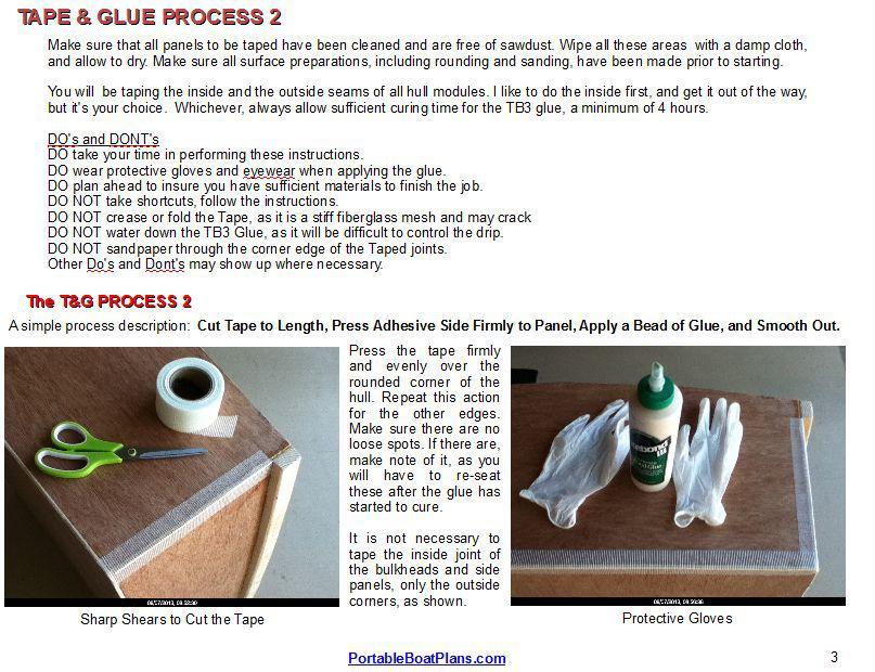
 FREE to print TAPE & GLUE PROCESS Version: Jun. 2011 The following small boat assembly process was developed out of the need for an easy, lightweight, cost effective and health friendly method of providing
More Storage Space Under Yacht Bed
 More Storage Space Under Yacht Bed Open up storage space under your bed! Convert your bed deck to a Lifting Hatch with Gas Spring assist! Many bed decks on boats and RV s have two or three pieces of plywood
Building Instructions Diva cabin boat
 Building Instructions Diva cabin boat Order no. 3093/00 aero-naut Modellbau Stuttgarterstr. 18-22 D-72766 Reutlingen / Germany http://www.aero-naut.com 1 For pictured building instructions please see the
Photo Essay Building a. Key Largo. Carolina Dory. Plans for this boat may be found at:
 Photo Essay Building a Key Largo Carolina Dory Plans for this boat may be found at: http://spirainternational.com/ Photo Essay Building a Key Largo Carolina Dory The Carolina Dory is a specialized type
Hatch Installation For Pygmy Solo and Double Kayaks
 Introduction/Overview Hatch Installation For Pygmy Solo and Double Kayaks The hatch kit consists of several wooden lips, strapping and hardware. The hatch is constructed by cutting a hole in your deck,
Harriet Chair with Modifications
 Harriet Chair with Modifications This modification of the Harriet chair includes a slat back, padded seat, and is 2 inches wider than the original plan. The overall dimensions of the finished chair: 38
Plans. Easy-to-Build Full-size Deluxe Murphy Bed Plan. For more plans, tools and hardware visit rockler.com
 Easy-to-Build Full-size Deluxe Murphy Bed Plan Build a full-size Deluxe Murphy Bed complete with decorative molding and matching side cabinets! Plans For more plans, tools and hardware visit rockler.com
The image above is intended to give you an idea of what the dovecote will look like when finished.
 Thank you for buying my book, I hope it is useful and enjoyable in your quest to building your own dovecote. This book will give you step-by step instructions on how to build your own dovecote also included
Corvus Racer CC
 Corvus Racer 540 35CC Item No:L-G035008 Specifications Wing Span Length Wing Area Flying Weight Glow Gasoline Electric Radio mm mm 1200sq in (77.4sqdm) 9.9-12lbs(4.5-5.5kg) 91-1.20(2C) 1.10-1.40(4C) 20-40cc
Wood Duck Nest Box Design & Assembly Directions
 Wood Duck Nest Box Design & Assembly Directions Instructions, Illustrations & Photos Courtesy of MWDI and Scott Jasion, Harford County Chapter, Ducks Unlimited Side door opening design for easy mounting
Nanton Grain Mill Assembly
 ( 1 ) Nanton Grain Mill Assembly Locate package for assembling storage building. These are cut from 1/8 masonite. Inspect and lightly sand edges where it will be bonded. Use white glue or CA glue to bond.
General Prisoner Transport Install Instructions PT-2-INST
 General Prisoner Transport Install Instructions PT-2-INST 50 or 60 high x 80, 100 & 120 inch long / Double Compartment Inserts Also refer to PT-A-3XX instructions for vehicle specific mounting measurements
The Festival Assembly Instructions
 The Festival Assembly Instructions Toll Free: 866.768.8465 Hours: 9-5 Monday-Friday EST www.homeplacestructures.com Package ships as shown CONTACT INFORMATION: HomePlace Structures 301 Commerce Drive New
90 WING SPAN P-51D MUSTANG (COPYRIGHT PROTECTED 2014) ALL RIGHTS RESERVED
 ALL RIGHTS RESERVED") 90 WING SPAN P-51D MUSTANG (COPYRIGHT PROTECTED 2014) ALL RIGHTS RESERVED GENERAL INSTRUCTIONS This design is basically an enlargement of the very popular fun scale Mustang 60 Size. You can build it light
90 WING SPAN P-51D MUSTANG (COPYRIGHT PROTECTED 2014) ALL RIGHTS RESERVED GENERAL INSTRUCTIONS This design is basically an enlargement of the very popular fun scale Mustang 60 Size. You can build it light
Bateau.com PH18 CNC kit notes 1/5
 Bateau.com PH18 CNC kit notes 1/5 These building notes must be used in conjunction with the standard building notes included in the plans package for this boat. The PH18 kit is assembled as described in
woodworkersjournal.com MATERIAL LIST
 MATERIAL LIST T x W x L 1 Legs (2) 1 1 2" x 3 1 2" x 36 7 16" 2 End Uprights (2) 1 1 2" x 3 1 2" x 32 1 2" 3 Stringers (4) 1 1 2" x 3 1 2" x 42" 4 Top Cladding, Long (2) 3/4" x 7 1 4" x 65 3 4" 5 Side
Photo Essay How to Build an. Alaskan. Grand Banks Dory. Plans for this boat may be found at:
 Photo Essay How to Build an Alaskan Grand Banks Dory Plans for this boat may be found at: http://www.spirainternational.com/ How to Build an Alaskan Grand Banks Dory The Alaskan is an easy to build Spira
Instructables Butcher Block Top
 Instructables Butcher Block Top Project Overview: This project requires basic woodworking skills and access to woodworking machines. Woodworking machines have sharp cutting edges and are NOT forgiving.
After the canopy hinge is square with the firewall and the nut plates are installed you can set up the hinge mounts. Start by clamping a 1/16 tongue
 Written by: Sean Cole September 19, 2008 When fitting the stiffener use 3/32 clecos to hold it in place, it makes a smaller hole and is easier to work with. Only use the amount needed to hold the stiffener
129 KITCHEN BASE CABINET 480
 129 KITCHEN BASE CABINET 480 There are two sorts of kitchen cabinets: base cabinets, which sit on the floor, and wall cabinets. Base cabinets provide both storage space and work surfaces. They often house
Chapter 23. Garage Construction
 Chapter 23. Garage Construction 23.1 ESTABLISHING CHALK LINES 23.2 MEASURING AND CUTTING WALL PLATES 23.3 MARKING WINDOW & DOOR LOCATIONS ON EXTERIOR WALL PLATES 23.4 MARKING STUDS ON EXTERIOR WALL PLATES
Pivot-Door Downdraft Cabinet Plans
 Pivot-Door Downdraft Cabinet Plans Finished Cabinet Closed Open Exploded View Introduction This simple downdraft-style dust collection cabinet is a great way to keep your shop cleaner and keep your router
FUSELAGE CONSTRUCTION
 FUSELAGE CONSTRUCTION Note: prior to building and gluing on the work surface use protective covering on your building surface. (wax paper or clear wrap) Fit the laser cut Fuselage Front and Fuselage Rear
Building Tips This model can be built using the following types of adhesives:
 Page 1 Building Tips This model can be built using the following types of adhesives: Epoxy (with or without microballons) Odorless cyanoacrylate (CA) with accelerator UHU Creativ for Styrofoam (or UHU
Assembly Instructions 10 X 10 Aluminum Frame Building
 Assembly Instructions 10 X 10 Aluminum Frame Building 27 97 9 8 47 36 74 52 10 10 X 10 Square Building W/ Dome Includes: The Steel Entry Door with a Dead Bolt Lock assembly and Aluminum Door Frame. Metal
Important Note: Why this guidebook is FREE?
 Easy DIY Murphy Bed Construction Guide 1 Important Note: This guide is a FREE SAMPLE of our Complete Construction Guidebook. With the help of this guide you will get familiar with the construction steps
Building Instructions
 Building Instructions Tools Required Tape measure Straight edge Pencil/pen Jigsaw Table Saw Circular Saw Electric drill 1 Hole saw bit Saw horses/table Protractor Staple gun Caulk gun Paint brush Wrenches
END FRAMES. End frames built using pressure treated 2x4 (1 1/2" x 3 1/2") 36" 34" 7/16" pilot hole. 5 1/2" x 1/2" lag bolt 8" wheel 23"
 36 34 7/16 pilot hole. 5 1/2 x 1/2 lag bolt 8 wheel 23") END FRAMES End frames built using pressure treated 2x4 (1 1/2" x 3 1/2") 23" 17 1/2" (B) (B) Measure from the bottom of your stone to 1" below the lip to get your measurement. 17 1/2"(B) 36" 34" 1/2" flat
END FRAMES End frames built using pressure treated 2x4 (1 1/2" x 3 1/2") 23" 17 1/2" (B) (B) Measure from the bottom of your stone to 1" below the lip to get your measurement. 17 1/2"(B) 36" 34" 1/2" flat
JAE Mini Sprint. Fast Electric Outrigger. A Zippkits R/C Boat. Building Instructions
 Z I P P M A N U FA C T U R I N G JAE Mini Sprint Fast Electric Outrigger A Zippkits R/C Boat Building Instructions 2011 Zipp Manufacturing - Frankfort, New York 13340 www.zippkits.com Toll Free (866) 922-ZIPP
Vinyl Gazebo Instructions
 P a g e 1 Vinyl Gazebo Instructions 10 Vinyl Gazebo Shown Thank you for the purchase of your New Gazebo. Depending on the size of your Gazebo, installation can usually be completed in 1 to 2 days. These
Chapter Six. Getting started inboard. Installing the false deck
 A close look at the thinning down of the bulkhead extensions. They are just 1/16 thick after fairing them. Chapter Six Getting started inboard This next step is one of the last remaining messy tasks to
Continue gluing the remaining top parts ensuring the angled piece is glued well. Set aside and let dry. See photo below
 Radiator rev 1.1 The SE5a s radiator is one of the most recognized radiators in WW1. It is one of the components that defines the SE5a. The original SE5a has seen multiple radiator designs used during
Wanderlust Suitcase Vanity
 Wanderlust Suitcase Vanity If you re like me, you re always up for an adventure. When I saw some examples of DIY reclaimed suitcases, paired with the exciting new Wanderlust embroidery design collection,
Tools and Tips: ( 1 )
") Tools and Tips: As you build instructions will show in my many picture manual how to assemble. You can use your own methods as you desire, my results are very good. A smooth, flat work surface is very
Tools and Tips: As you build instructions will show in my many picture manual how to assemble. You can use your own methods as you desire, my results are very good. A smooth, flat work surface is very
Low/High Tunnel Greenhouse Plans
 Low/High Tunnel Greenhouse Plans Tools Needed (See the complete list of Greenhouse Tools) Hacksaw or Reciprocating Saw Socket Wrench, Adjustable Wrench or Nut Drivers Electric Drill with Drill Bits Sledge
Mousetrap Catapult. About this project:
 Designed by: Ritchie Kinmont Project #44 Page 1/19 About this project: The is fun for ages four and up. Using a mousetrap for the spring, this catapult is designed to throw objects such as practice golf
A Skin-on-Frame Pram. Designed by Dana Munkelt. Drawings by Andrew Walters. Duckworks Boatbuilder's Supply duckworksbbs.com
 A Skin-on-Frame Pram Designed by Dana Munkelt Drawings by Andrew Walters Duckworks Boatbuilder's Supply duckworksbbs.com "" is a small skin-on-frame (SOF) pram design with a twist; a solid plywood floor.
Metal Aircraft Landing Light Installation Instructions
 Metal Aircraft Landing Light Installation Instructions This landing light kit was designed for the Thorp T-18 as a method of installing a halogen landing light in the leading edge of the outer bay of the
Tools and Tips: ( 1 )
") Tools and Tips: As you build instructions will show in my many picture manual how to assemble. You can use your own methods as you desire, my results are very good. A smooth, flat work surface is very
Tools and Tips: As you build instructions will show in my many picture manual how to assemble. You can use your own methods as you desire, my results are very good. A smooth, flat work surface is very
Butterfly Leaf Dining Table Plans
 Butterfly Leaf Dining Table Plans Part 1 An attractive dining table with a secret: the leaf folds and stores inside the table. Season 1, Episode 7 P a g e 2 I first saw a butterfly leaf table in a back
Use these notes in conjunction with the plans and the plan's building notes.
 GF18 CNC kit notes. Use these notes in conjunction with the plans and the plan's building notes. The standard kit is based on the GF18 with the sole option, central bench included. There are small differences
Balustrade Systems / Installation Instructions
 A. PARTS AND SUPPLIES NEEDED FOR INSTALLATION Hardware included for each 10 section of rail: 2 3 x 1-1/2 L-brackets 4 1-3/4 x 3/16 Blue hex-head screws for anchoring the L-brackets to the newel cap, column
Big Oz. Rocket. User Guide V0313
 Big Oz Rocket User Guide 59824 V0313 Materials Included The Big Oz Rocket Kit should include the following materials. If something is missing, contact Customer Service at 800-358-4983. 20-ounce plastic
12. Wings, Flaps, Ailerons and Struts
 12. Wings, Flaps, Ailerons and Struts Fit Aileron Hinges Reference: Drawing 20270K2 Photo 12.1 Parts Required: 2007092 Aileron LS 200809N Aileron RS 2001394 Hinge 3/16 A1 (4) 2001694 Hinge Pin (4) PH0059N
Above are the offsets for the plywood panels.
 DinkyDink Plans Bottom Panel Half Station X Y X2 Y2 1 1/4 3/4 0 11 5/16 2 4 9/16 4 12 9/16 3 11 11/16 1/4 11 7/16 14 1/2 4 18 5/8 1/16 18 5/8 15 11/16 5 25 3/4 0 25 3/4 16 5/16 6 32 13/16 0 32 13/16 16
Why are we giving this guidebook as a FREE download?
 Construction Guide Queen, Double & Twin Vertical 1 Note: This guide covers the construction steps for all 3 sizes of the vertical wall mount Easy DIY Murphy beds, Queen, Double and Twin. The construction
Chapter Ten. Continuation of all inboard details
 Chapter Ten Continuation of all inboard details Inboard stern details There are several details at the stern that need to be completed. The photo above shows all of them finished and painted. Let us break
Hobby Lobby Zip Supplementary instructions Please refer to the included drawings while using these assembly instructions
 Materials needed: 15 or 30 minute epoxy Medium CA Masking tape Scotch tape Servo Tape Wax paper Tools Needed: Pencil or marker Flat building surface Hobby knife or razor blade 7/64" or 3mm drill bit 3/16"
Installation Instructions for. Before You Begin TOOLS REQUIRED
 Composite Railing System STEP-BY-STEP Installation Instructions for Spectrum Composite Railing Virtually maintenance free 20-year warranty EverNew Spectrum Railing system is designed to work with a number
Assembly Instructions: Bencher Skylark
 Assembly Instructions: Bencher Skylark Tools Required: Pop Rivet Tool Tape Measure Hex Wrenches Screwdriver Several Disposable Rags Two Saw Horses Several boxes or bowls to hold fasteners and small parts
Introduction: The model should be assembled following the sequence of the stages of construction described in these instructions.
 Victoria Bestell-Nr. 3082/00 Introduction: The model should be assembled following the sequence of the stages of construction described in these instructions. The laser-cut components are individually
Installation And Care Instructions. Vertical Honeycomb Shades
 Installation And Care Instructions Vertical Honeycomb Shades Rev 5/2013 Table Of Contents Getting Started... 3 Parts Overview... 4 Materials Required... 5 Tools Required... 6 Outside Mount Installation...
10. Wing prep and subassembly
 Date Section Objective: Construct and fabricate the sub-assemblies of the wing panel. Required Parts: Wing left 11gal PN104-300, Wing right 1gal PN104-400, Wing left 15 gal option PN104-322, Wing right
ULTIMATE ROUTER TABLE PLANS. By Dan Phalen
 ULTIMATE ROUTER TABLE PLANS By Dan Phalen January 2017 Ultimate Router Table Plans. Copyright 2012-2017 by Daniel Phalen. Published by Creston Hall Publishing Company. All rights reserved. No part of this
Installation Guidelines
 Page 1 Two inch () Porch Screening System Extruded Screen Walls Only Kit Installation Guidelines Tools You ll Need 4 ft. Carpenter s level Chalk line (to mark U channel locations) Chop saw with a metal
Central New York Rocket Team Challenge 2018 Rocket Assembly Instructions
 Central New York Rocket Team Challenge 2018 Rocket Assembly Instructions Note: These instructions vary from those provided by the manufacturer of the rocket kits. There is also considerable varying discussion
Max Launch Abort System Prod. No *Kevlar is a registered trademark of Dupont
 Flying Model Parts List Max Launch Abort System Prod. No. 3014 A 11820 - Body Tube 3.5 Diam x 5.5" Long B 11824 - Orange Capsule Base Shoulder Ring C 16032 - Laser-cut Ring motor mount rear D 16033 - Laser-cut
Installation Instructions for Siding
 Smart-Shingle TM System "The new smart way to install cedar shingles." - This Old House Installation Instructions for Siding V3.2 INSTALLATION GUIDE MARKS Shingle-Strip 0 1 2 3 4 5 6 7 8 9 10 11 12 13
ALIEN ENCLOSURES CAMARO AND FIREBIRD Trunk Panel Kit Instructions
 ALIEN ENCLOSURES 67-69 CAMARO AND FIREBIRD Trunk Panel Kit Instructions TYPICAL TOOLS & MATERIALS NEEDED FOR UPHOLSTERY 2 Yards of Main Panel Material 1.5 Yards of Backer Material 3 yards of foam backing
by John Correll written February 2015
 1 Simple Way to Install a Liftable Floorboard or Casting Deck in a Boat (without using a fixed underlying support structure that tends to interfere with access to the compartment) by John Correll written
Kitchen Upper Cabinet: Double Doors Cabinets from Scratch
 Kitchen Upper Cabinet: Double Doors by Cabinets from Scratch Our Home from Scratch LLC Page 1 Disclaimer Our Home from Scratch LLC and its legal owners cannot be held responsible for any loss, damage,
11) Chromate the mating surfaces of the Leading edge Root Rib, Doubler and Root Rib Stiffeners. Rivet together with 1/8 rivets (RV-1410).
 Chromate the mating surfaces of the Leading edge Root Rib, Doubler and Root Rib Stiffeners. Rivet together with 1/8 rivets (RV-1410).") 11) Chromate the mating surfaces of the Leading edge Root Rib, Doubler and Root Rib Stiffeners. Rivet together with 1/8 rivets (RV-1410). 12) Chromate the Root Rib Attach Bracket and rivet to the Root
11) Chromate the mating surfaces of the Leading edge Root Rib, Doubler and Root Rib Stiffeners. Rivet together with 1/8 rivets (RV-1410). 12) Chromate the Root Rib Attach Bracket and rivet to the Root
Case Building Instructions For Derbywizard Freedom Aluminum Tracks
 Case Building Instructions For Derbywizard Freedom Aluminum Tracks You can easily build a hard storage case for your new track by following these simple instructions. Materials Case Width (W): 2 ln = 8.75",
Front Vise 70G G08.02
 Front Vise 70G08.01 70G08.02 The following instructions guide you through the installation of either the Regular Front Vise (70G08.01) or the Large Front Vise (70G08.02). The first step is to determine
Hinge Mortising Jig. One of the make it or break it parts of building a. 6 ShopNotes No. 74
 Hinge Mortising Jig A Mortise for a Hinge. Quick, clean, and accurate that s the only way to describe the mortise you get with a trim router and this hinge mortising jig. One of the make it or break it
Redwood strips are tacked to the templates, and edge-glued. Drive brads through into the templates before putting on fiberglass doth.
 1 Make the building form and attach templates to the crosspieces. Nail a strip down the center to hold the stems and templates in position. prototype canoe took about three weekends to build. She's broad
96 WING SPAN SPITFIRE (COPYRIGHT PROTECTED 2014) ALL RIGHTS RESERVED
 ALL RIGHTS RESERVED") 96 WING SPAN SPITFIRE (COPYRIGHT PROTECTED 2014) ALL RIGHTS RESERVED GENERAL INSTRUCTIONS Should you elect to use the recommended Door Skin, which is 1/8 mahogany plywood measuring 36 x 88. Have it cut
96 WING SPAN SPITFIRE (COPYRIGHT PROTECTED 2014) ALL RIGHTS RESERVED GENERAL INSTRUCTIONS Should you elect to use the recommended Door Skin, which is 1/8 mahogany plywood measuring 36 x 88. Have it cut
STANDARD CANOPY WORK REPORT B-1
 STANDARD CANOPY WORK REPORT B-1 No. Check Parts / Tools Qty _ Canopy Lock 1 [ ] 6E2-3 Canopy Hinge Block 1 2 [ ] 6E4-5 Canopy Side Frame 2 2 [ ] 6E2-1 Canopy Lock Assembly 1L + 1R 3 [ ] 6E2-4 Rear Lock
V nyl Gazebo truct c it Assembly Instr ons
 V nyl Gazebo Vi Assembly Instr ct tr t u ru ons ct c i ti Pre-assembly Instructions A C B #1 - Site properly prepared. 4" - 6" clean stone 9 linear blocks 2" x 8" x 16" C C A A B B #1a - 12" sauna tubes,
CUSTOM SHUTTERS IN-A-BOX
 CUSTOM SHUTTERS IN-A-BOX SHUTTER ASSEMBLE INSTRUCTIONS & INSTALLATION INSTRUCTIONS 1. Inspect the contents of your package. Do not discard the shutter packaging box until you have started painting your
FireFighter.21 Building Instructions
 A Tom Moorehouse design. Thank-you for purchasing the FireFighter.21. I believe that you will find it to be the best.21 rigger kit available. It has won 1 st place in the 2006 AMPBA nationals! It was designed
MXS R 30CC. Item No:L G Specifications. 67 1/2"(1720mm) (2C) (4C) 26 35cc gas DLE 30/35RA MLD35 JC30Evo.
 (2C) (4C) 26 35cc gas DLE 30/35RA MLD35 JC30Evo.") MXS R 30CC Item No:L G030008 Specifications Wing Span Length Wing Area Flying Weight Glow Gasoline Electric Radio Description Covering Material Carbon Fibre : 75"(1915mm) 67 1/2"(1720mm) 1023sq in(66sq
MXS R 30CC Item No:L G030008 Specifications Wing Span Length Wing Area Flying Weight Glow Gasoline Electric Radio Description Covering Material Carbon Fibre : 75"(1915mm) 67 1/2"(1720mm) 1023sq in(66sq
Router Table. Construction
 Router Table A router table is an invaluable tool. The problem, however, is that ready-built router tables are usually relatively expensive and too narrow for many projects. This router table provides
PoorBoy Skiff. A 10-11ft 6in skiff for outboard motoring By Steven Lewis
 PoorBoy Skiff. A 10-11ft 6in skiff for outboard motoring By Steven Lewis PoorBoy is about the simplest small motorboat you will come across. It consists of 2-2 1/4 sheets of plywood (1-1 1/4 sheets x3/8
Frameless Inline Door With Return QCI5263
 INSTALLATION INSTRUCTIONS Frameless Inline Door With Return QCI5263 WALL MOUNT HINGES FRAMELESS DOOR / PANEL / RETURN PANEL QCI5263 REV. 0 Page 1 Certified 06/17/2016 Parts List with wall mount hinges
Making Simple Bookbinding Equipment
 Tony Firman 20 1 2 19 Notes Tony Firman Tony Firman Bookbinding 18 3 : 2012 Tony Firman Bookbinding P.O. Box 507 Haslet, TX 76052 www.tonyfirmanbookbinding.com 4. When all the tapes have been pinned in
A Day House. A View of One Way to Finish the Exterior of The Day House. Read these instructions all the way through before beginning this project.
 A Day House A View of One Way to Finish the Exterior of The Day House Read these instructions all the way through before beginning this project. General Comments For the purposes of this project, the standard
VACUSEAL MODEL 200. HOT TUB PRODUCTS 233 Carrington Road Bethany CT
 VACUSEAL MODEL 200 J G F G H L HOT TUB PRODUCTS 233 Carrington Road Bethany CT 06524 860-469-2580 www.vacusealcoverlift.com www.hottubproducts.com Made in USA H K E D C I A P B 10 9 8 7 6 5 4 3 2 1 0 SPAS
COMPLIMENTARY WOODWORKING PLAN
 COMPLIMENTARY WOODWORKING PLAN ORIENTAL GARDEN ARBOR PLAN This downloadable plan is copyrighted. Please do not share or redistribute this plan in any way. It has been paid for on your behalf by JET Tools,
Cardboard Cup Regatta Plans and Directions
 To help celebrate the upcoming Crystal Lake America s Cardboard Cup Regatta, we have asked a veteran of 18 races to submit a set of plans and directions to build an unsinkable and competitive cardboard
How to build a Javelin Skiff
 How to build a Javelin Skiff This is not your grandfather s plywood boat! The Javelin involves a high-tech type construction, called composite. The hull can be constructed with foam or plywood; these materials
REVISION LIST CHAPTER 25: AFT WINDOWS. The following list of revisions will allow you to update the Legacy construction manual chapter listed above.
 REVISION LIST CHAPTER 25: The following list of revisions will allow you to update the Legacy construction manual chapter listed above. Under the Action column, R&R directs you to remove and replace the
Assembly Instructions for 12x16 Floating Dock
 Assembly Instructions for 12x16 Floating Dock www.rollingbarge.com Congratulations on the purchase of your Floating Dock kit. This kit includes all the aluminum frame parts, and all the fasteners. You
PRIVACY INSTALLATION FOR: Standard 6 H x 8 W Privacy Fence 4 x 4 Post Sleeve & Brackets Dog Ear or Straight-Edge Pickets 1.75 x 3.
 PRIVACY INSTALLATION FOR: Standard 6 H x 8 W Privacy Fence 4 x 4 Post Sleeve & Brackets Dog Ear or Straight-Edge Pickets 1.75 x 3.5 Rail Storage and Handling Fence Preparation and Layout Locate and Set
Copyright 1998 KDE Technologies
 Modular Computer Corner Desk Unit Copyright 1998 KDE Technologies http://members.tripod.com/~kdetech/ 1. Introduction 2. Plans Sheet one - Isometric Sheet two - Top Detail / Corner Unit Sheet three - Leg
EmagiKit. Privacy Pod Plus. Quiet. Easy. Affordable. INSTRUCTIONS ASSEMBLY
 EmagiKit Privacy Pod Plus Quiet. Easy. Affordable. INSTRUCTIONS ASSEMBLY DIMENSIONS AND COMPONENTS 47 47 Ceiling Unit 2-B 2-L 2-R Glass Door Corner Trim Door Handle 90 Adjustable Height Work Surface 1-B
Edge 540 V3 35CC. Scheme A. Item No:L G Specifications. Flying Weight
 Edge 540 V3 35CC Item No:L G035016 Specifications Wing Span Length Wing Area Flying Weight Glow Gasoline Electric Radio Description 76 (1930mm) 74 (1879mm) 1200sq in(77.4sqdm) 9.9 12lbs(4.5 5.5kg) 91 1.20(2C)
 America s leading woodworking authority To download these plans, you will need Adobe Reader installed on your computer. If you want to get a free copy, visit: http://adobe.com/ reader. Having trouble downloading
Installation Instructions
 www.marlite.com Effective Date 03/01/2018 ARTIZAN FRP, SYMMETRIX FRP, ENVUE FRP, STANDARD FRP Installation Instructions Statements expressed in this technical bulletin are recommendations for the application
Router Table-Mate. Everything you'd want in a router table for just $50.
 Router Table-Mate Everything you'd want in a router table for just $50. Commercially made router tables are everywhere these days. Some of them come with more gizmos and gadgets than a 59 Edsel. By the
SE5a Instrument Board part 2 - rev 1.1
 SE5a Instrument Board part 2 - rev 1.1 Fuel (Petrol) Valve This valve uses two circular name plates, eight brass screws, one black plastic base, copper wire and two black plastic risers. You can pick any
BUILDING A STORM DOOR
 BUILDING A STORM DOOR BY NEAL BARRETT Illustrations by George Retseck If you're in the market for a storm door, you probably know that there are many styles and models available. However, most of them
Skybolt V2 Construction Manual
 Skybolt V2 Construction Manual Property of www.ppgplans.com Do not duplicate or make public. Warnings & Disclaimers. This product shows how to build a basic frame only for Powered Paragliding. It is the
Build your own Drawer unit. D3 / D4
 Page1 Build your own Drawer unit. D3 / D4 1: Introduction. This guide will give you the plans, materials and how to information to build your own drawer unit. The dimensions given will fit a D3 or D4,
PRIVACY FENCE WITH LATTICE INSTALLATION INSTRUCTIONS
 PRIVACY FENCE WITH LATTICE INSTALLATION INSTRUCTIONS These instructions are to be used as general guidelines for the installation of your vinyl fence under normal installation conditions. Local conditions