Absco Workshop Shed Model: 45302WK
|
|
|
- Margaret Neal
- 5 years ago
- Views:
Transcription


1 Absco Workshop Shed Model: FRONT: 4.48m SIDE: 3.0m HEIGHT: 2.m CONCRETE SLAB 300mm 4580mm CONCRETE WHEN LAYING YOUR CONCRETE SLAB, ENSURE THERE IS A REBATED EDGE 25mm DEEP AROUND THE PERIMETER 00mm REBATED EDGE CONCRETE SLAB THIS WILL HELP WATER EGRESS FROM THE BASE OF THE SHED 75mm WIDE REBATE We thank you for choosng an Australan made shed. For further assstance please vst our detaled nstructonal vdeo lbrary at At ABSCO Industres we are always lookng to be number ONE, so please let us know what you thnk of our nstructons. Feedback makes us better. feedback@absco.com.au PAGE


.")


2 SITE PREPARATION Local Authorty approval must be obtaned pror to constructon of the shed. Once you have selected your ste you wll need to lodge a ste plan to your local councl. The ste for the shed must be level. It s recommended that the shed be set on a 00mm concrete slab and anchored down approprately (refer page 23 for detals). Anchor sets are not suppled as standard tems wth ths product. GENERAL INSTRUCTIONS Before commencng any assembly, read through these nstructons n detal to gan a thorough understandng of assembly methods and assocated detals. Unpack the carton and carefully dentfy and check off all the parts aganst the parts descrbed and llustrated on pages three and four. TOOLS REQUIRED 3mm 4mm A NOTE ON SAFETY OPTIONAL Some parts may have sharp edges. It s advsable to wear gloves when handlng these tems and safety glasses f drllng holes. Sensble shoes are hghly recommended. Do not erect your shed n wndy condtons, ensure that the shed s securely anchored to a sold foundaton mmedately after constructon s completed. It s hghly recommended to erect the shed wth two or more people. PAGE 2
3 COMPONENTS PACKING LIST - CHECK OFF ALL COMPONENTS MAIN PACK CARTON (PACK OF 2) QTY COMPONENT DESCRIPTION PART No. CHECK QTY COMPONENT DESCRIPTION PART No. CHECK 2 STEEL SHEET 95mm X 773mm 36L RIDGE BEAM 97AL L = 52mm 2 STEEL SHEET 2045mm X 773mm 38L RIDGE BEAM 97AR L = 52mm 2 STEEL SHEET 546mm X 773mm RIDGE BEAM 97C L = 53mm STEEL SHEET 785mm X 7mm 34A RIDGE BEAM JOINER L: 450mm (7.7") ZARSP STEEL SHEET 785mm X 7mm 35A 2 5A PEAK BRACE STEEL SHEET 725mm X 773mm A FITTINGS & ACCESSORIES PACKET (SEE PAGE 4) STEEL SHEET 725mm X 773mm B PAGE 3
4 COMPONENTS PACKING LIST - (CONT.) CHECK OFF ALL COMPONENTS FITTINGS & ACCESSORIES PACKET CONTENTS 2 DOOR STRAP L: 65mm 2A 0 JOINER L= 200mm (7.9") CSJ 2 CAP GABLE L: 70mm 4A RIDGE 2 PLATES RBP 8 SELF DRILLING HEX HEAD TEK SCREWS (NO HOLE REQUIRED) FAST035 RIDGE CAP JOINER 98A HEX TEK SCREW FAST023 DRIVER BIT ASSEMBLY INSTRUCTIONS PHILLIPS HEAD DRIVER FAST038 PSTKSGL SINGLE DOOR FITTINGS PACK 3mm (0.2") DRILL BIT DRILL PSTKSGL - SINGLE DOOR FITTINGS PACK PSTKSGL DOUBLE DOOR FITTINGS PACK DOOR PADBOLT 22A DOOR PADBOLT HASP SELF TAPPING SCREWS PACKET CONTAINING 220 PACK 6P SCREW PACK 6 PACK 6P - SCREW PACK 6 6 3/6 COUNTERSUNK SCREWS & NUTS x 8mm BLIND POP RIVETS PSTKDBL - DOUBLE DOOR FITTINGS PACK 3 DOOR PADBOLT 22A 2 DOOR PADBOLT HASP SELF TAPPING SCREWS PACKET CONTAINING 220 PACK2P SCREW PACK 2 PACK2P - SCREW PACK 2 8 3/6 ROUND HEAD BOLTS & NYLOCK NUTS x 8mm BLIND POP RIVETS 2 3/6 COUNTERSUNK SCREWS & NUTS PAGE 4
5 COMPONENTS PACKING LIST - (CONT.) CHECK OFF ALL COMPONENTS MAIN PACK CARTON (PACK 2 OF 2) QTY COMPONENT DESCRIPTION PART No. CHECK QTY COMPONENT DESCRIPTION PART No. CHECK 2 STEEL SHEET 95mm X 773mm 36R 5 STEEL SHEET 785mm X 773mm 3A 2 STEEL SHEET 2045mm X 773mm 38R 3 STEEL SHEET 785mm X 773mm 30A L = 482mm C WCP-(J) PACK (SEE PGs 6 & 7) L = 704mm C704 PORTAL FRAME FITTINGS PACK (SEE BELOW) PORTAL FRAME ACCESSORIES 2 KNEE PLATE 4 DYNABOLT 2 APEX PLATE 20 6mm TEK SCREWS 2 MULTI PURPOSE BRACKET 26 45mm TEK SCREWS PAGE 5
6 COMPONENTS PACKING LIST - (CONT.) CHECK OFF ALL COMPONENTS 45302WCP PACK QTY COMPONENT DESCRIPTION PART No. CHECK QTY COMPONENT DESCRIPTION PART No. CHECK L = 496.5mm 55AL L = 496.5mm 55AR L = 496.5mm 55BL L = 496.5mm 55BR L = 496.5mm 55CL L = 496.5mm 55CR 2 60AL L = 496.5mm 2 60AR 2 L = 496.5mm 4 L = 496.5mm 8AL 4 L = 496.5mm 8AR L = 496.5mm 8BL L = 496.5mm 8BR PAGE 6
7 COMPONENTS PACKING LIST - (CONT.) CHECK OFF ALL COMPONENTS 45302WCP PACK (CONT.) QTY COMPONENT DESCRIPTION PART No. CHECK QTY COMPONENT DESCRIPTION PART No. CHECK 2 WITH HINGES L = 725mm 58A 2 L = 58mm 84L L = 725mm 58B 2 L = 58mm 84R 2 L = 53mm 53C 2 JAMB L= 785mm 89A 4 L = 773mm 58C JAMB L= 725mm 89C 2 L = 53mm 60C JAMB L= 568mm 90A L = 568mm 79A 4 JAMB L= 20mm 9A 2 L = 53mm 8E 4 LIP TRIM L= 546mm 87A 2 L = 53mm 8F PAGE 7

 x 3mm (0.2\") (2 PER A SIDE) HOLES TO SECURE SECTIONS TOGETHER.")
. Push the CSJ nto the channel untl you here a 'clck'.")
8 INSTRUCTIONS FOR JOINING SPLICED S NOTE: THE TEXT MARKED ON ALL PARTS MUST BE SHOWN ON THE SAME SIDE AS EACH OTHER. = = = = CSJ JOIN>> <<JOIN JOIN>> = = J JOIN>> SJ STEP. Poston the channels and the CSJ joner channel so the center of the CSJ s n lne wth the end of each channel to be joned together. STEP 2. Jon the frst channel to the CSJ by nsertng the center of the CSJ (on an angle) to the end of the channel where the JOIN>> text s marked. Push down one sde of the CSJ untl you hear a 'clck'. = = JOIN>> <<JOIN JOIN>> = <<JOIN = DRILL 4mm (0.6") x 3mm (0.2") (2 PER A SIDE) HOLES TO SECURE SECTIONS TOGETHER. (THESE SCREWS MAY HAVE TO BE TEMPORARILY REMOVED AND REPLACED DURING LATER ASSEMBLY) STEP 3. Jon the second channel to the CSJ by postonng the <<JOIN end of the channel at the center of the CSJ (on an angle). Push the CSJ nto the channel untl you here a 'clck'. FINISHED The joned channels should now look lke the pcture above wth the CSJ postoned equally nsde of the joned channels. PUSH QTY = 0pcs. CSJ PUSH CSJ CSJ CSJ HIGH-SIDE CSJ LOW-SIDE 20mm (0.79") CSJ 5mm (0.59") PAGE 8
9 STEP. PRE-ASSEMBLY OF SPLICED S NOTE: JOIN TOGETHER 20 X SECTIONS USING 0 X JOINERS (PART CSJ) 4 X 8AR 4 X 8AL 2 X 60AR 2 X 60AL X 55AR X 55AL X 55BR X 55BL NOTE: SOME S HAVE HOLES IN THEM - YOU WILL NEED TO RE-DRILL HOLES ON ANY WHERE THE CSJ JOINING COVERS HOLES ON THE S YOU ARE CONNECTING 55BL 2993mm (7.8") 60AR 8CR 8CL 60AL 55BR 55AL 55AR 8BR 55CL 55CR = = = = = = 4 x 8A 2 x 60A x 55A x 55B x 55C x 8B X 55CR X 55CL 8BL X 8BR X 8BL PAGE 9


10 INSTRUCTIONS FOR JOINING SPLICED RIDGE BEAM STAGE : PUSH RIDGE BEAMS TOGETHER, MAKE SURE THERE IS A 50mm OVERLAP OF THE RIDGE CAP STAGE 2: INSERT RIDGE CAP JOINER INTO CONNECTED RIDGE CAPS. MAKE SURE JOINER HAS 225mm IN EACH RIDGE CAP. STAGE 3: TURN RIDGE CAP OVER AND MEASURE 250mm FROM THE END OF EACH RIDGE CAP. PLACE TEK SCREWS IN 50mm INCREMENTS FROM SAID END. REPEAT THIS PROCESS FOR THE OPPOSING HALF OF RIDGE BEAM PAGE 0
11 STEP 2. PRE-ASSEMBLY OF SPLICED RIDGE BEAM QTY. = TEK SCREW DRIVER BIT QTY. = 8 SELF DRILLING TEK SCREW QTY. = 2 RIDGE BEAM 52mm (59.9") PARTS 97AL & 97AR QTY. = PUSH PUSH PART ZARSP - 450mm (7.7") LONG 6mm (0.63") 97AR ZARSP 200mm (7.9") 250mm (9.8") 97AL 6mm (0.63") (PART 97A) 2993mm (7.8") OVERALL LENGTH THE TOP SECTIONS OF CAPPING WILL OVERLAP EACH OTHER AT THE JOIN BY 50mm (2.0"). PAGE

12 VIEW OF ROOF COMPONENTS 87A 60A 8A 8E 98A 87A 60C 60C 97C 4A 87A 8E 97A 4A 60A 8A 87A PAGE 2
13 Absco Workshop Shed Model: 55B 30A 36R 53C 3A 3A 5A PF 30A 3A 3A 90A 84L 8B 84R 53C 36L 35A 38L 38R 3A 8F 36R 30A 8A 55C VIEW OF WALL COMPONENTS 8F 84R 38R 9A 89A 9A 22A 5A 38L 36L 34A 89A 79A 84L A 55A 8A B PAGE 3

14 ABSCO ASSEMBLY INTRODUCTION The snap-tte assembly system locks all permeter channels to all roof and wall sheets wthout the need for tools and fasteners. To pre-assemble the four wall panels and two roof panels, the permeter channels are secured to the top and bottom of each panel usng the snaptte system, as detaled on the followng pages wherever you see the symbol. HIGH SIDE PUSH HIGH SIDE HIGH SIDE HIGH SIDE PUSH After jonng sheets together, poston channel over one end of the sheets, gently tappng t over the snaptte lugs, workng along the sheets to the other end. PUSH Poston sheets on tmbers, trestles or partly over edge of concrete slab. FASTENING SYMBOLS HIGH SIDE Each permeter channel must fnsh flush wth the edges of the sheets. the snap-tte system allows adjustment for ths process by smply tappng the channel along the sheets untl each end s neatly flush. Jon components together wth one screw at ths locaton only, as some channel sectons have extra holes that are not requred for ths model of garden shed 3mm POP RIVETS 4mm NUT & BOLT SET Do not jon components together at ths locaton yet, as the screw may obstruct further assembly of other components SELF DRILLING TEK SCREW FOR JOINING PORTAL FRAME COMPONENTS PAGE 4


15 DOOR DOOR PANEL ASSEMBLY 58C 58C 58A 58B B A 2A 58C 58A 58C 89C ALL VERTICAL DOOR S ARE INSTALLED IN THE REVERSE DIRECTION IN COMPARISON TO HORIZONTAL DOOR S B A 20mm FLANGE 5mm FLANGE FOUR HOLE SET FOR PADBOLT CONNECTION PAGE 5
16 SMALL PANEL ( Requred) REAR PANEL ASSEMBLY LARGE PANEL ( Requred) 30A 3A 3A 30A 3A 3A 53C 55B 8F 8B PAGE 6
17 SIDE PANEL ASSEMBLY (2 Requred) TRIM THE TIP OF EACH SHEET OR BEND OUT OF THE WAY TO ALLOW S TO FIT HARD UP TO THE EDGE OF THE SHEET 38L 38R 36R 36L 84R 5A 84L 8A INSIDE OF SHED PAGE 7
18 LARGE ROOF PANEL ASSEMBLY (2 Requred) NOTE: ONE ROOF PANEL WILL HAVE PART (87A) FITTED TO THIS END ONLY. 60A NOTE: ONE ROOF PANEL WILL HAVE PART (87A) FITTED TO THIS END ONLY. 87A 2/PRE-PUNCHED HOLES TO THIS END OF EACH SHEET WITH PART No. 8A FITTED 8A 87A PAGE 8
19 SMALL ROOF PANEL ASSEMBLY (2 Requred) NOTE: ONE ROOF PANEL WILL HAVE PART (87A) FITTED TO THIS END ONLY. NOTE: ONE ROOF PANEL WILL HAVE PART (87A) FITTED TO THIS END ONLY. 60C 87A 2/PRE-PUNCHED HOLES TO THIS END OF EACH SHEET WITH PART No. 8E FITTED 87A 8E PAGE 9
20 FRONT DOOR PANEL ASSEMBLY 89A 89A 34A 35A 55A 90A 79A 55C PAGE 20
21 FRONT PANEL ASSEMBLY ( Requred) 3A 30A 53C 8F PAGE 2
22 DOOR PANEL ASSEMBLY 9A 9A B A NOTE: Nuts and bolts (suppled) may be used nstead of pop rvets (suppled) by smply enlargng the hnge hole sets n the jamb usng a 4mm drll bt NOTE: The two holes requred to connect the padbolt hasp for each door have not been pre-punched, to allow for proper algnment. poston each hasp centrally over the padbolt shaft, and drll 3mm holes and secure wth screws PAGE 22
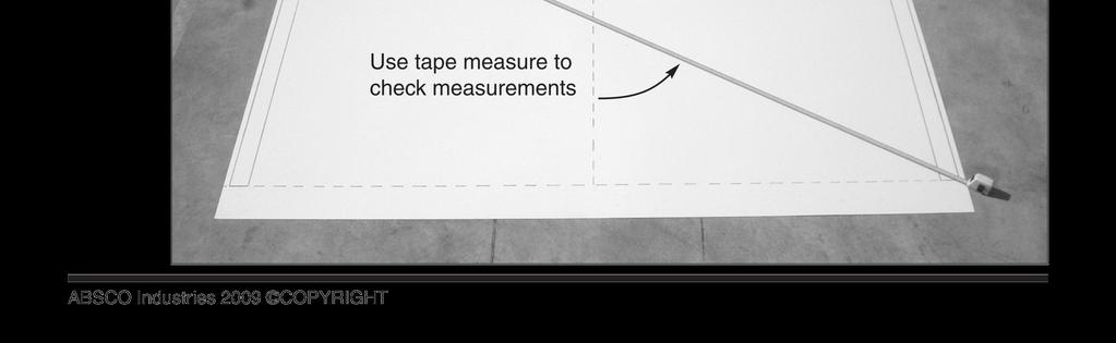
23 CENTRE PORTAL FRAME DETAILS REFER TO PAGE 6 FOR PORTAL FRAME PARTS AND ACCESSORIES 80mm PART C482 PART C mm 80mm FRAME ASSEMBLY AN EASY WAY TO ENSURE THAT THE ANGLE AT THE TOP OF THE PORTAL FRAME IS CORRECT IS TO USE THE GABLE WALL PANEL AS A TEMPLATE TO LAY THE SECTIONS OUT. AS THE PORTAL FRAME FITS INSIDE THE WALLS, THE WIDTH OF THE FRAME WILL BE 40mm LESS THAN THE GABLE WALL PANEL. 2045mm 2950mm 2 x APEX PLATES NOTE: PLEASE REFER TO THE PHOTOS ON PAGES 24-3 FOR CLARITY X KNEE PLATE x KNEE PLATE NOTE: REFER TO THE FOLLOWING PAGE FOR FURTHER DETAILS. NOTE: IF YOU HAVE AN EDGE REBATE IN YOUR CONCRETE SLAB, YOU WILL HAVE TO CUT AN AMOUNT OFF THE BOTTOM OF THE FRAME LEGS EQUAL TO THE DEPTH OF THE REBATE. PAGE 23
24 x 9. CENTRE PORTAL FRAME ASSEMBLY SECURE RIDGE PLATES TO APEX PLATES = x x 8 3. x x 4. SLAB CENTRE LINE SLAB SIZE: 4580 x 300 x 6 (REFER: PANEL CONSTRUCTION) 45mm TEK SCREW WALL PANEL WALL PANEL 2 CENTRE LINE SLAB/PORTAL FRAME/WALL PANELS PORTAL FRAME PAGE 24
25 PANEL CONSTRUCTION NOTE: TAKE CARE TO ENSURE THAT BOTH FRONT AND REAR WALL PANELS ARE NOT POSITIONED UPSIDE DOWN. THE TOP OF EACH PANEL IS PRE-PUNCHED FOR ATTACHING ROOF SHEETS, THE BOTTOM S ARE NOT. SIDE WALL PANEL S FIT INTO THE NOTCHED FRONT AND REAR WALL PANEL S USE 45mm SELF DRILLING SCREWS TO SECURE WALLS TO CENTRE FRAME PRE-PUNCHED TO MATCH RIDGE BEAM HOLES. SHEETING PRE-PUNCHED THIS END TO FOR CONNECTION TO FRONT AND REAR WALLS PAGE 25
26 ROOF CONSTRUCTION SECURE EACH RIDGE BEAM TO EACH RIDGE PLATE WITH 4 X 6mm SELF DRILLING TEK SCREWS. INSIDE VIEW OF FIXING X4 A B SECURE PEAK BRACE TO RIDGE BEAM AND ROOF PANEL WITH ONE SCREW AT EACH END MOVE THE OTHER ROOF PANEL INTO POSITION AND SECURE PEAK BRACE TO RIDGE BEAM AND ROOF PANEL WITH ONE SCREW AT EACH END SECURE BOTH ROOF PANELS TO THE WALLS WITH ONE SCREW IN EACH CORNER FIRST, FOLLOWED BY TWO SCREWS ADJACENT TO THE PORTAL FRAME AS SHOWN ABOVE SECURE ROOF PANELS TO THE TOP CHORDS OF THE PORTAL FRAME USING 45mm SELF DRILLING TEK SCREWS. PAGE 26
27 FINAL CONSTRUCTION BEND THE TOP AND BOTTOM FLANGES AS SHOWN, THEN HOOK THE BOTTOM FLANGES UNDER THE TOP AND SCREW THE TOP FLANGES FOR BOTH AS SHOWN GABLE CAPS ANCHORING OF SHED LOCATION OF 6 CONCRETE ANCHORS - EACH ANCHOR CONSISTS OF ONE NUT, BOLT, DYNABOLT AND STEEL ANGLE - DRILL A 0mm HOLE INTO THE WALL SHEET BOLT & NUT STEEL ANGLE WALL SHEET SLAB - DRILL A 0mm HOLE INTO THE CONCRETE DYNABOLT PAGE 27
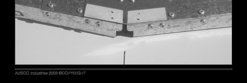
 Secure mult purpose")
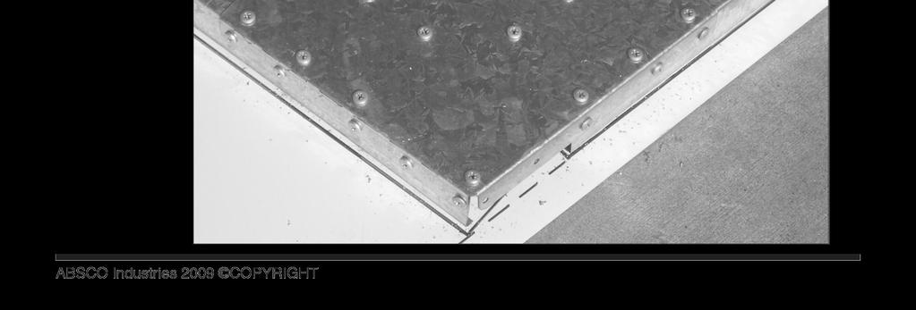
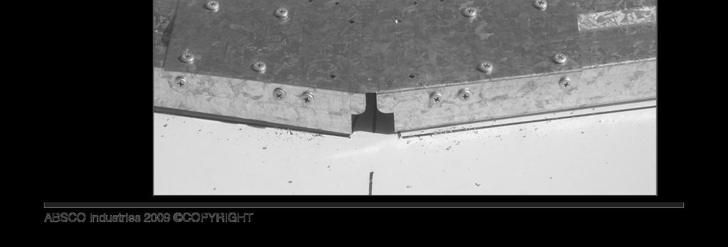
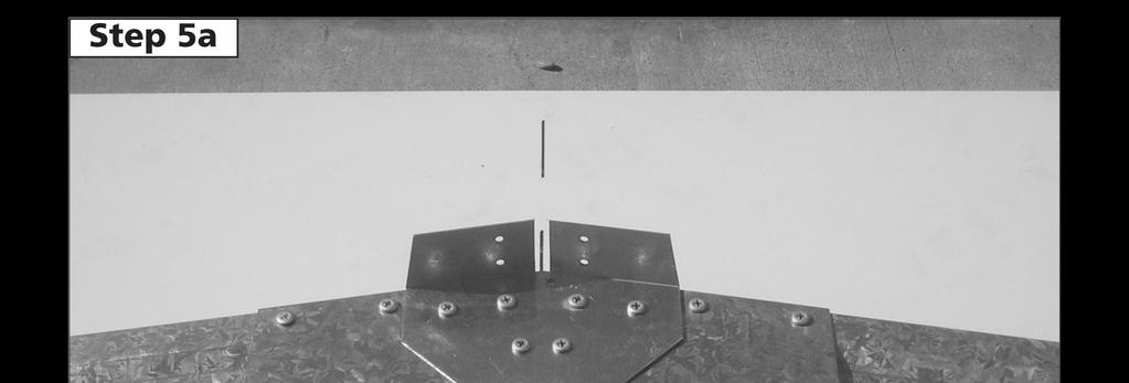
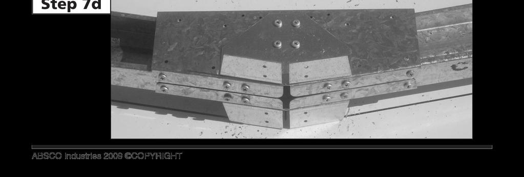
28 ABSCO CENTRE PORTAL FRAME ASSEMBLY ASSEMBLY SUPPORT PHOTOGRAPHS STEP A, B, C: Draw pattern on concrete, n accordance wth the dmensons detaled n the assembly nstructon. STEP 2A, B, C: Understand where components are to be postoned STEP 3A, B, C: Jon C482 to C704 STEP 4A, B, C: Jon C482 to C482 STEP 5A, B: STEP 6A, B: Secure rdge plate (RBP) Secure mult purpose brackets STEP 7A, B, C, D: Turn frame over, repeat steps 4,5 PAGE 28


29 PAGE 29


30 PAGE 30


31 PAGE 3


32 PAGE 32


33 PAGE 33


34 PAGE 34


35 PAGE 35


36


37
Absco Space Saver Shed Assembly Instructions Model: J30082S
 Assembly Instructons FRONT BASE LENGTH: 9ft-0-7 64n SIDE BASE LENGTH: ft-6-45 64n FRONT WALL HEIGHT: 5ft-0-55 64n REAR WALL HEIGHT: 6ft-4-49 64n ft-0-4 64n CONCRETE SLAB 0ft--3 64n CONCRETE SLAB WHEN LAYING
Absco Space Saver Shed Assembly Instructions Model: 23081SK
 Assembly Instructons Model: 2308SK FRONT BASE LENGTH: 2.26m SIDE BASE LENGTH: 0.78m FRONT WALL HEIGHT:.80m REAR WALL HEIGHT:.95m CONCRETE SLAB 880mm 2360mm WHEN LAYING YOUR CONCRETE SLAB, CHAMFER THE 50mm
Absco EZISLIM Shed Model: 08151F
 FRONT: 0.78m SIDE: 1.52m HEIGHT: 1.80m CONCRETE SLAB 1620mm 880mm WHEN LAYING YOUR CONCRETE SLAB, CHAMFER THE 50mm EDGES DOWNWARDS BY 10mm. 50mm 10mm 50mm THIS WILL ENSURE THAT WATER RUN OFF IS KEPT CLEAR
Absco Pool Pump Cover Assembly Instructions Model: PPCK
 Cover Assembly Instructons Model: PPCK EXTERNAL BASE DIMENSIONS: 520mm x 520mm EXTERNAL REAR WALL HEIGHT: 490mm EXTERNAL FRONT WALL HEIGHT: 220mm RECOMMENDED CONCRETE SLAB SIZE: 620mm x 620mm x 00mm THICK
Absco Premier Garden Shed Assembly Instructions Model: J30302G
 Absco Premier Garden Shed Assembly Instructions FRONT: 9' 0 7 64" SIDE: 9' 0 7 64" HEIGHT: 6' 0 43 64" 0' 3 64" CONCRETE SLAB 0' 3 64" CONCRETE SLAB WHEN LAYING YOUR CONCRETE SLAB, ENSURE THERE IS A REBATED
Absco Premier Garden Shed Assembly Instructions Model: J30302G
 Absco Premier Garden Shed Assembly Instructions FRONT: 9ft-0-7 64in SIDE: 9ft-0-7 64in HEIGHT: 6ft-0-43 64in 0ft--3 64in CONCRETE SLAB 0ft--3 64in CONCRETE SLAB WHEN LAYING YOUR CONCRETE SLAB, ENSURE THERE
Organic Garden Co. Aviary Assembly Instructions Model: AOGC15081FKFD
 Assembly Instructons Model: AOGC508FKF FRONT:.52m SIE : 0.78m HEIGHT:.8m CONCRETE SLAB 880 620mm WHEN LAYING YOUR CONCRETE SLAB, CHAMFER THE 50mm EGES OWNWARS BY 0mm. 50mm 0mm 50mm THIS WILL ENSURE THAT
Absco Aviary Assembly Instructions Model: AOGC15151F
 Absco Avary Assembly Instructons FRONT:.52m SIE :.48m HEIGHT:.8m 580 CONCRETE SLAB 620mm WHEN LAYING YOUR CONCRETE SLAB, CHAMFER THE 50mm EGES OWNWARS BY 0mm. 50mm 0mm 50mm THIS WILL ENSURE THAT WATER
Absco Premier Garden Shed Assembly Instructions Model: 23231GK
 Absco Premier Garden Shed Assembly Instructions Model: 33GK FRONT:.6m SIDE:.6m HEIGHT:.00m 360mm CONCRETE SLAB 360mm WHEN LAYING YOUR CONCRETE SLAB, CHAMFER THE 50mm EDGES DOWNWARDS BY 0mm. 50mm 0mm 50mm
Absco Regent Shed Assembly Instructions Model: J30372R
 Absco Regent Shed Assembly Instructions FRONT: 9ft-0-7 64in SIDE: ft-3 3in HEIGHT: 6ft-0-43 64in ft-4-3in CONCRETE SLAB 0ft--3 64in CONCRETE SLAB WHEN LAYING YOUR CONCRETE SLAB, ENSURE THERE IS A REBATED
Absco Space Saver Shed Assembly Instructions Model: J30082S
 Assembly Instructions FRONT BASE LENGTH: 9' 0 7 64" SIDE BASE LENGTH: ' 6 45 64" FRONT WALL HEIGHT: 5' 0 55 64" REAR WALL HEIGHT: 6' 4 49 64" CONCRETE SLAB ' 0 4 64" 0' 3 64" CONCRETE SLAB WHEN LAYING
Absco Workshop Shed Model: 45232WK
 FRONT: 4.48m SIDE:.6m HEIGHT:.00m CONCRETE SLAB 360mm 4580mm CONCRETE WHEN LAYING YOUR CONCRETE SLAB, ENSURE THERE IS A REBATED EDGE 5mm DEEP AROUND THE PERIMETER 00mm REBATED EDGE CONCRETE SLAB THIS WILL
Absco Space Saver Shed Assembly Instructions Model: 15081S
 Assembly Instructions FRONT BASE LENGTH:.5m SIDE BASE LENGTH: 0.78m FRONT WALL HEIGHT:.8m REAR WALL HEIGHT:.95m CONCRETE SLAB 60mm 880mm WHEN LAYING YOUR CONCRETE SLAB, CHAMFER THE 50mm EDGES DOWNWARDS
Absco Industries Workshop Shed Model: 60303WK
 FRONT: 5.96m SIDE: 3.00m HEIGHT:.0m CONCRETE SLAB 300mm 6060mm WHEN LAYING YOUR CONCRETE SLAB, ENSURE THERE IS A REBATED EDGE 5mm DEEP AROUND THE PERIMETER THIS WILL HELP WATER EGRESS FROM THE BASE OF
Absco Highlander Shed Model: 3045HK
 FOR CONSTRUCTION IN NON-CYCLONIC AREAS WIND RATING: W33N (N2) FRONT: 3.0 m SIDE: 4.48m HEIGHT: 2.3 m CONCRETE SLAB 300mm 4580mm CONCRETE WHEN LAYING YOUR CONCRETE SLAB, ENSURE THERE IS A REBATED EDGE 25mm
Premier Garden Shed Assembly Instructions Model: J30232GK
 Assembly Instructons Model: J303GK 360mm (7.7") CONCRETE SLAB 300mm (0.7'') FRONT: 3.0m (9.84") SIDE:.6m (7.4") HEIGHT:.m (6.88") WHEN LAYING YOUR CONCRETE SLAB, CHAMFER THE 50mm EDGES DOWNWARDS BY 0mm
Absco Premier Garden Shed Assembly Instructions Model: 30302GK
 Absco Premer Garden Shed Assembly Instructons FRONT: 3.0m SIDE: 3.0m HEIGHT:.m 300mm CONCRETE SLAB 300mm WHEN LAYING YOUR CONCRETE SLAB, CHAMFER THE 50mm EDGES DOWNWARDS BY 0mm. 50mm 0mm 50mm THIS WILL
Absco Regent Garden Shed Assembly Instructions Model: 30372RK
 Shed Assembly Instructons Model: 3037RK FRONT: 3.0m SIDE: 3.66m HEIGHT:.m 3760mm CONCRETE SLAB 300mm CONCRETE WHEN LAYING YOUR CONCRETE SLAB, ENSURE THERE IS A REBATED EDGE 5mm DEEP AROUND THE PERIMETER
INSTRUCTION MANUAL J23232GK
 We thank you for choosing an Australian Made Shed. For further assistance please visit our detailed instructional video library at Http://www.abscosheds.com.au/watch-videos At ABSCO Industries we are always
Absco Aviary Assembly Instructions Model: A15301FK
 Absco Avary Assembly Instructons Model: A15301FK FRONT: 1.52m SIE : 2.96m HEIGHT: 1.8m 3060mm CONCRETE SLAB 1620mm WHEN LAYING YOUR CONCRETE SLAB, CHAMFER THE 50mm EGES OWNWARS BY 10mm. 50mm 10mm 50mm
Absco Aviary Assembly Instructions Model: A23231G
 Absco Aviary Assembly Instructions Model: A23231G FRONT: 2.26m SIDE : 2.22m HEIGHT: 1.96m WHEN LAYING YOUR CONCRETE SLAB, CHAMFER THE 50mm EDGES DOWNWARDS BY 10mm. 50mm 10mm 50mm THIS WILL ENSURE THAT
MODEL No: GSS3030G. Model No:...GSS3030G Overall Size (W x D X H*) x 3000 x 2100mm Roof Type:...Gable *Minimum Wall Height
 x 3000 x 2100mm Roof Type:...Gable *Minimum Wall Height") 1. SAFETY INSTRUCTIONS INSTRUCTIONS FOR: GALVANIZED STEEL SHED GREEN 3 x 3 x 2.1m MODEL No: GSS3030G Thank you for purchasing a Sealey product. Manufactured to a high standard, this product will, if used
1. SAFETY INSTRUCTIONS INSTRUCTIONS FOR: GALVANIZED STEEL SHED GREEN 3 x 3 x 2.1m MODEL No: GSS3030G Thank you for purchasing a Sealey product. Manufactured to a high standard, this product will, if used
SteelChief Installation Instructions for pre-assembled panel form sheds GABLE ROOF
 SteelChief Installation Instructions for pre-assembled panel form sheds GABLE ROOF Please read fully before commencing work...any queries will be promptly answered, contact theboss@steelchief.com.aui MPORTANT
GALVANIZED SHED GREEN 2.3 X 2.3 X 1.9m
 INSTRUCTIONS FOR: GALVANIZED SHED GREEN 2.3 X 2.3 X 1.9m MODEL NO: GSS2323G Thank you for purchasing a Sealey product. Manufactured to a high standard, this product will, if used according to these instructions,
Installation Manual for Metal Emperor Lockers
 P a g e 1 Table of Contents Page General Notes and Tools Required 2-3 Assemble Shelves with Coat Hooks/Coat Rods 4 Fastening Chart 5 Knock Down Locker Assembly (Banks of Three) 6-12 Appendix A: Dress End
INSTRUCTIONS FOR: GALVANIZED STEEL SHED 3 x 3 x 2.1mtr. MODEL No: GSS3030
 INSTRUCTIONS FOR: GALVANIZED STEEL SHED 3 x 3 x 2.1mtr MODEL No: GSS3030 Thank you for purchasing a Sealey product. Manufactured to a high standard this product will, if used according to these instructions
E N G L I S H GARDEN SHED. Assembly Instructions. Suitable for Models WITH VARYING DEPTHS
 GARDEN SHED Assembly Instructions Suitable for Models 6' Wide 8' Wide 0' Wide WITH VARYING DEPTHS GI0003 November 0 INSTALLATION ADVICE It's Not That Difficult! The construction of your shed isn't as complicated
Track Rack. * Track Racks are not lockable
 The Track Rack s unique staggered, sliding hook design creates the greatest parking efficiency while still providing easy access to any particular bike. When adding or removing a bike to the rack, simply
It is important that you contact your local government authority to determine if building approval is required.
 HANDI-MATE SHED HANDI-MATE LOCKER INSTALLATION GUIDE INSTALL GUIDE BEFORE YOU START PRIOR TO INSTALLATION It is important that you contact your local government authority to determine if building approval
ASSEMBLY INSTRUCTIONS GG77. BASE SIZE: 2.190m x 2.020m
 ASSEMBLY INSTRUCTIONS GG77 BASE SIZE: 2.190m x 2.020m CONGRATULATIONS ON PURCHASING A DURATUF GUARDIAN SHED. BEFORE YOU BEGIN THE ASSEMBLY PLEASE NOTE SOME IMPORTANT POINTS: BEFORE YOU START: Read all
GALVANIZED SHED 2.3 X 2.3 X 1.9M
 INSTRUCTIONS FOR GALVANIZED SHED 2.3 X 2.3 X 1.9M MODEL NO: GSS2323 & GSS2323G Thank you for purchasing a Sealey product. Manufactured to a high standard, this product will, if used according to these
INSTALLING YOUR NEW SPRING LIFT ARM KIT
 INSTALLING YOUR NEW SPRING LIFT ARM KIT 1. Measure the distance that the roof is to be raised. [If your lift system is completely non-functional, you will need to calculate or estimate this distance as
Safety Glasses Safety Gloves Ladders Measuring Tape Spirit Level String Line. Tin-Snips Rivet Gun Caulking Gun Silicone Socket Set
 BEFORE YOU START Carefully read these instructions and refer to them constantly during each stage of construction. If you do not have all the necessary tools or information, contact Stratco for advice.
ASSEMBLY INSTRUCTIONS SS2520. BASE SIZE: 2.520m x 2.020m
 ASSEMBLY INSTRUCTIONS SS50 BASE SIZE:.50m x.00m CONGRATULATIONS ON PURCHASING A SMART STORE SHED. BEFORE YOU BEGIN THE ASSEMBLY PLEASE NOTE SOME IMPORTANT POINTS: BEFORE YOU START: Read all instructions
English/French 06/04
 E000 PLEASE READ ASSEMBLY INSTRUCTIONS COMPLETELY BEFORE ASSEMBLING YOUR BUILDING CAUTION: Some parts have sharp edges. Care must be taken when handling the various pieces to avoid a mishap. For safety
DUTCH GABLE CARPORT RECOMMENDED INSTRUCTION MANUAL
 DUTCH GABLE CARPORT RECOMMENDED INSTRUCTION MANUAL Table of Contents Introduction 2 Components 3 Step 1a Marking out the Perimeter of the Carport with Footing only 4 Step 2a Footing Set-Out for Concrete
GALVANIZED STEEL SHED 1510 x 1510 x 1900mm
 INSTRUCTIONS FOR: GALVANIZED STEEL SHED 1510 x 1510 x 1900mm MODEL No s: GSS1515.V2, GSS1515G.V2 Thank you for purchasing a Sealey product. Manufactured to a high standard, this product will, if used according
Dura-Lock Roof System
 DLR-14 Dura-Lock Roof System Assembly and Installation Instructions Read the instructions before starting the job. They explain the steps required to produce a finished product that will meet factory specifications.
PINEHAVEN SHEDS Assembly Instructions FOR LEAN-TO SHEDS
 PINEHAVEN SHEDS Assembly Instructions FOR LEAN-TO SHEDS GARDEN PRODUCTS www.pinehavensheds.co.nz 5/16 hex drive bit, By asking about our products at your nearest DIY or gardening store www.pinehavensheds.co.nz
FLAT ROOF CARPORT RECOMMENDED INSTRUCTION MANUAL
 FLAT ROOF CARPORT RECOMMENDED INSTRUCTION MANUAL Table of Contents Introduction... 2 Components... 3 Step 1 Marking out the Perimeter of the Carport... 3 Step 2a Footing Set-Out for Concrete Block Pad
S H E D A S S E M B L Y I N S T R U C T I O N S
 T I T A N R A N G E S H E D A S S E M B L Y I N S T R U C T I O N S 6 X 4ft = 190 x 150 cm 6 X 6ft = 190 x 190 cm 6 X 8ft = 190 x 255 cm COMPONENT LIST Component illustrations are given as a visual guide
HANDI-MATE SHED BEFORE YOU START INSTALL GUIDE HINGED DOOR HANDI-MATE INSTALLATION GUIDE PRIOR TO INSTALLATION
 HANDI-MATE SHED HINGED DOOR HANDI-MATE INSTALLATION GUIDE INSTALL GUIDE BEFORE YOU START PRIOR TO INSTALLATION It is important that you contact your local government authority to determine if building
ASSEMBLY INSTRUCTIONS FOR STORETTE STA42
 ASSEMBLY INSTRUCTIONS FOR STORETTE STA42 A01 CAUTION: Some parts have sharp edges. Care must be taken when handling the various pieces to avoid a mishap. For safety sake, please read the safety information
Appendix B Framing Component Installation Last updated 5/27/2013
 Appendix B Framing Component Installation Last updated 5/27/2013 Apex Brace Installation Appendix B 1 Refer to apex connection detail on the engineering plans for the location of the apex brace. Refer
GABLE ROOF CARPORT RECOMMENDED INSTRUCTION MANUAL
 GABLE ROOF CARPORT RECOMMENDED INSTRUCTION MANUAL Table of Contents Introduction 2 Components 3 Step 1a Marking out the Perimeter of the Carport with Footing only 3 Step 2a Footing Set-Out for Concrete
AWNING / PATIO COVER INSTALLATION INSTRUCTIONS
 AWNING / PATIO COVER INSTALLATION INSTRUCTIONS Before You Begin Read the installation instructions thoroughly before beginning the installation procedure. Perspective In the Awning Instructions, Back means
INSTALLATION GUIDE. Flat Roof Homesheds TM. Onto Concrete BEFORE YOU START TOOLS REQUIRED
 INSTALLATION GUIDE Flat Roof Homesheds TM Onto Concrete BEFORE YOU START It is important to check your Local Government Authority requirements before the installation of your new Stratco Flat Roof Homeshed.
Model No. EP84-A, EP84AR-A, P84L
 E000 Model No. EP84-A, EP84AR-A, P84L PLEASE READ ASSEMBLY INSTRUCTIONS COMPLETELY BEFORE ASSEMBLING YOUR BUILDING CAUTION: Some parts have sharp edges. Care must be taken when handling the various pieces
INSTRUCTIONS FOR ASSEMBLY 2355mm x 3125mm Workshop
 Manufacturer of Christie Glasshouses and Sheds INSTRUCTIONS FOR ASSEMBLY 2355mm x 3125mm Workshop 1 Thomas Burns Street, Dunedin Phone (03) 477 7909 www.allans.co.nz Congratulations on your purchase of
S H E D A S S E M B L Y I N S T R U C T I O N S
 T I T A N R A N G E S H E D A S S E M B L Y I N S T R U C T I O N S 8 X 10 ft Approx = 2550 x 3140 cm COMPONENT LIST Component illustrations are given as a visual guide only and are not in proportion PART
ASSEMBLY INSTRUCTIONS
 GARDEN SHED 6X5ft B/C 9400988362649 GARDEN SHED 6X7ft B/C 9400988362656 GARDEN SHED 6X9ft B/C 9400988362663 GARDEN SHED 6X1 B/C 9400988362670 111 ft ASSEMBLY INSTRUCTIONS Product specifications may change
ALL SEASON PATIO COVER
 ALL SEASON PATIO COVER 61 Where the All Season Patio Cover is to be attached to the home, create a level line showing where the top of the mounting rail is to be located. Install each section with the
INSTRUCTIONS FOR: GALVANIZED STEEL SHED GREEN 1.5 x 0.8 x1.5m
 INSTRUCTIONS FOR: GALVANIZED STEEL SHED GREEN 1.5 x 0.8 x1.5m MODEL NO: GSS150815G Thank you for purchasing a Sealey product. Manufactured to a high standard, this product will, if used according to these
INSTRUCTIONS FOR ASSEMBLY 2355mm x 4665mm Workshop
 Manufacturer of Christie Glasshouses and Sheds INSTRUCTIONS FOR ASSEMBLY 2355mm x 4665mm Workshop 1 Thomas Burns Street, Dunedin Phone (03) 477 7909 www.allans.co.nz Congratulations on your purchase of
CONTENTS TOOL LIST U P S I D E I N N O V A T I O N S, L L C RAMP AND STEP SYSTEM ASSEMBLY INSTRUCTIONS. Revised: June 2013
 U P S I D E I N N O V A T I O N S, L L C RAMP AND STEP SYSTEM ASSEMBLY INSTRUCTIONS TOOL LIST Required Tools: - Reciprocating Saw with Metal Cutting Blade - Drill - 7/16 Drill Bit for Metal Drilling -
GROWING BETTER THROUGH DESIGN. 6ft Lean-To LEAN-TO. Assembly Instructions 04/02
 GROWING BETTER THROUGH DESIGN 6ft Lean-To LEAN-TO Assembly Instructions 04/02 6ft Lean-To Greenhouse Base Plan Introduction/Tools/Contents / / Contents This is a copy of our Lean-To greenhouse base plan.
GALVANIZED STEEL SHED GREEN 1.5 X 1.5 X 1.9M
 INSTRUCTIONS FOR: GALVANIZED STEEL SHED GREEN 1.5 X 1.5 X 1.9M MODEL NO: GSS1515G Thank you for purchasing a Sealey product. Manufactured to a high standard, this product will, if used according to these
RH-412 STEEL DOORS INSTALLATION INSTRUCTIONS
 RH-412 STEEL DOORS INSTALLATION INSTRUCTIONS By following the steps outlined below, the assembly, installation and adjustment of the steel doors, will be a simple process. Let s start with the Driver Side.
GALVANIZED STEEL SHED 1.5 x 0.8 x 1.5M
 INSTRUCTIONS FOR GALVANIZED STEEL SHED 1.5 x 0.8 x 1.5M MODEL NO: GSS150815G Thank you for purchasing a Sealey product. Manufactured to a high standard, this product will, if used according to these instructions,
INSTALLATION INSTRUCTIONS RH 412 STEEL DOORS
 By following the steps outlined below, the assembly, installation and adjustment of the steel doors, will be a simple process. Let s start with the Driver Side. Note: Having the hood open makes the job
GM3015 ASSEMBLY. 1 cardboard package 1 channel pack. Tools supplied: 1 Riveter 3.3mm double ended drillbit. Tools required: Tape measure Ladder
 M3015 SLOPIN ROO SHED 3030mm wide x 1530mm deep x 1980-1830mm high 25 YER WRRNTY SSEMBLY INSTRUCTION DVD WITH LL SHEDS SSEMBLY INSTRUCTIONS You should have two packages: 1 cardboard package 1 channel pack
1.6M X 2.4M GARDEN SHED ASSEMBLY INSTRUCTIONS EZ-16242
 .6M X.4M GARDEN SHED ASSEMBLY INSTRUCTIONS EZ-64 Congratulations on purchasing your new proudly South African eazished. Before commencing the assembly, we recommend that you read the instructions thoroughly.
Ensure there is reasonable access for materials and working space, ensure the shed site is level and consider the disposal of run-off water.
 INSTALLATION GUIDE TM Flat Roof Homesheds THE POTTER BEFORE YOU START It is important to check your Local Government Authority requirements before the installation of your new Stratco Potter Flat Roof
ASSEMBLY INSTRUCTIONS
 Quality Built In ASSEMBLY INSTRUCTIONS MK4B BASE SIZE 4210mm x 3380mm ASSEMBLY INSTRUCTIONS Tools Required: Drill Drill Bit 3.5mm Drill Bit 6mm (for clear roof panel only) Hex Drive 5/16 Riveter Hammer
ASSEMBLY INSTRUCTIONS GL75. BASE SIZE: 2.190m x 1.520m
 ASSEMBLY INSTRUCTIONS GL75 BASE SIZE: 2.190m x 1.520m CONGRATULATIONS ON PURCHASING A DURATUF GUARDIAN SHED. BEFORE YOU BEGIN THE ASSEMBLY PLEASE NOTE SOME IMPORTANT POINTS: BEFORE YOU START: Read all
STRATCO GABLE HOMESHED STRATCO GABLE HOMESHEDS STUBBIE INSTALLATION GUIDE
 STRATCO GABLE HOMESHED STRATCO GABLE HOMESHEDS STUBBIE INSTALLATION GUIDE INSTALL GUIDE BEFORE YOU START COUNCIL APPROVAL It is important that you have local council approval before building your Stratco
ASSEMBLY INSTRUCTIONS SS2010. BASE SIZE: 2.020m x 1.020m
 ASSEMBLY INSTRUCTIONS SS010 BASE SIZE:.00m x 1.00m CONGRATULATIONS ON PURCHASING A SMART STORE SHED. BEFORE YOU BEGIN THE ASSEMBLY PLEASE NOTE SOME IMPORTANT POINTS: BEFORE YOU START: Read all instructions
Before Assembling the Storage Wall
 Chapter 1 Assembling the Lista Storage Wall Lista provides two types of standard Storage Walls: B251 and B255. The design, construction, assembly, and quality are identical for both types, however, B251
ASSEMBLY INSTRUCTIONS
 Quality Built In ASSEMBLY INSTRUCTIONS MK3 BASE SIZE 3380mm x 1715mm ASSEMBLY INSTRUCTIONS Tools Required: Drill Drill Bit 3.5mm Drill Bit 6mm (for clear roof panel only) Hex Drive 5/16 Riveter Hammer
TRADITIONAL GABLE ATTACHED PATIO AND CARPORT. Your complete guide to building an ATTACHED Outback TRADITIONAL GABLE PATIO or CARPORT
 TRADITIONAL GABLE ATTACHED PATIO AND CARPORT STRATCO OUTBACK ASSEMBLY INSTRUCTIONS. Your complete guide to building an ATTACHED Outback TRADITIONAL GABLE PATIO or CARPORT BEFORE YOU START Carefully read
DUTCH GABLE FREESTANDING CARPORT
 DUTCH GABLE FREESTANDING CARPORT STRATCO OUTBACK ASSEMBLY INSTRUCTIONS. Your complete guide to building a FREESTANDING Outback DUTCH GABLE CARPORT BEFORE YOU START Carefully read these instructions. If
TrendWall Floor-To-Ceiling Panels Installation Instruction
 TrendWall Floor-To-Ceiling Panels Installation Instruction TrendWall Components Covered by this Instruction: Crown (and accessories) Floor Plate Solid Panel Filler Panel Wall Channel Door Section Pilaster
Owner's Manual & Assembly Instructions
 Owner's Manual & Assembly Instructions XZ0 Model No. GSA83 76300 Storage Area: 3 Sq. Ft. Cu. Ft., m 3,5 m 3 BUILDING DIMENSIONS * Size rounded off to the nearest foot CAUTION: SOME PARTS HAVE SHARP EDGES.
Assembly instructions. 6x4. Model GH1354A. 6x6. Model GH1357A. 6x8. Model GH1360A. 6x10. Walk-in Greenhouse. Model GH1363A
 ssembly instructions x Model GH x Model GH7 x8 Model GH0 x0 Model GH Walk-in Greenhouse Statement ear Customer! May we congratulate you on your new Greenhouse. We feel sure that by following the detailed
WORKSHOP. 1015HDDA, 1019HDDA m WALL HEIGHT 1015HDDA2, 1019HDDA2-2m WALL HEIGHT OPTIONAL SINGLE HINGED DOOR INSTRUCTION MANUAL INCLUDED
 DOUBLE HINGED DOOR 15 19 WORKSHOP 1015HDDA, 1019HDDA - 1.78m WALL HEIGHT 1015HDDA2, 1019HDDA2-2m WALL HEIGHT OPTIONAL SINGLE HINGED DOOR INSTRUCTION MANUAL INCLUDED (Available in Australia only) TRECO
Assembly Instructions
 Unite Panel System Hinge Door July 2016 #12 x / slotted hex washer head bolt Figure 1 threshold bracket frame Detail F threshold bracket threshold bracket (installed) #12 x / slotted hex washer head bolt
INSTALLATION GUIDE. Flat Roof Homesheds TM BEFORE YOU START TOOLS REQUIRED
 INSTALLATION GUIDE Flat Roof Homesheds TM BEFORE YOU START It is important to check your Local Government Authority requirements before the installation of your new Stratco Flat Roof Homeshed. Read these
TOOLS REQUIRED FOR ASSEMBLY. Rubber Mallet or Plastic Tip Hammer PARTS REQUIRED FOR ASSEMBLY OF SINGLE ENTRY STARTER.
 TOOLS REQUIRED FOR ASSEMBLY Rubber Mallet or Plastic Tip Hammer Top Cover Support PARTS REQUIRED FOR ASSEMBLY OF SINGLE ENTRY STARTER Back Stop Divider Closed 'L' Upright Slotted Reinforcement Support
WORKSHOP 1015A, 1019A m WALL HEIGHT 1015A2, 1019A2-2m WALL HEIGHT
 DOUBLE SLIDING DOOR 15 19 WORKSHOP 1015A, 1019A - 1.78m WALL HEIGHT 1015A2, 1019A2-2m WALL HEIGHT OPTIONAL SINGLE HINGED DOOR INSTRUCTION MANUAL INCLUDED (Available in Australia only) TRECO SHEDS ARE MANUFACTURED
GM1511 ASSEMBLY. 1 cardboard package. Tools supplied: 1 Riveter 3.3mm double ended drillbit. Tools required: Tape measure Ladder
 GM1511 SLOPING ROO SHD 1530mm wide x 1080mm deep x 1830-1770mm high 25 YAR WARRANTY ASSMLY INSTRUCTION DVD WITH ALL SHDS ASSMLY INSTRUCTIONS You should have one package: 1 cardboard package Tools supplied:
IDAHO ASSEMBLY INSTRUCTIONS. BASE SIZE: 1.800m x 1.200m
 IDAHO ASSEMBLY INSTRUCTIONS BASE SIZE: 1.800m x 1.200m IDAHO Tools Required: Battery Drill Riveter Hammer Tape Measure Ladder Skillsaw Level Square Drive Bit No.2 3/8 Hex Drive Bit 8mm Hex Drive Bit Drill
6 5 Wide TRADITIONAL CEDAR GREENHOUSE
 6 5 Wide TRADITIONAL CEDAR GREENHOUSE ASSEMBLY INSTRUCTIONS PLEASE READ ALL INSTRUCTIONS BEFORE PROCEEDING 08/04 6 5 WIDE TRADITIONAL CEDAR GREENHOUSE Assembly Instructions Contents Page Introduction 3
Best Barns USA Assembly Book
 Best Barns USA Assembly Book Revised September 19, 2016 the Meadowbrook-R 16' x 10' Manufactured by Reynolds Building Systems, Inc. 205 Arlington Drive Greenville, PA 16125 724-646-3775 This manual is
NEVADA ASSEMBLY INSTRUCTIONS
 NEVADA ASSEMBLY INSTRUCTIONS BASE SIZE: 2.700m x 1.500m NEVADA Tools Required: Battery Drill Riveter Hammer Tape Measure Ladder Skillsaw Level Screwdriver - Flat 3/8 Hex Drive bit 8mm Hex Drive bit Drill
10 Wide AMATEUR CEDAR GREENHOUSE
 10 Wide AMATEUR CEDAR GREENHOUSE ASSEMBLY INSTRUCTIONS Our Help Line provides support and advice to customers of Summer Greenhouses after ordering. For advice before you buy phone us free 7 days a week
Assembly Book. 10' x 16' the Cambridge II. revised July 15, 2014
 Assembly Book revised July 15, 2014 the Cambridge II 10' x 16' Manufactured by Reynolds Building Systems, Inc. 205 Arlington Drive Greenville, PA 16125 724-646-3775 This manual is copyrighted. Under the
Potting Store Assembly Instructions
 Before assembly We recommend that time is taken to read the instructions before starting assembly, then follow the easy step by step guide. The instruction sheet is only a guide to the assembly. Certain
8x12 SpaceMaker Garden Shed Assembly Manual
 8x12 SpaceMaker Garden Shed Assembly Manual Version #6 Revised June / 2007 Thank you for purchasing a 8x12 SpaceMaker Garden Shed. Please take the time to identify all the parts prior to assembly. Safety
8 Wide AMATEUR CEDAR GREENHOUSE
 8 Wide AMATEUR CEDAR GREENHOUSE ASSEMBLY INSTRUCTIONS Our Help Line provides support and advice to customers of Summer Greenhouses after ordering. For advice before you buy phone us free 7 days a week
ASSEMBLY INSTRUCTIONS FOR MODELS CG105, CG106, CG107, CG108, CG109 HD105, HD106, HD107, HD108, HD109 WO105, WO106, WO107, WO108, WO109 AAA01
 ASSEMBLY INSTRUCTIONS FOR MODELS CG105, CG106, CG107, CG108, CG109 HD105, HD106, HD107, HD108, HD109 WO105, WO106, WO107, WO108, WO109 AAA01 100% CANADIAN CAUTION: Some parts have sharp edges. Care must
PRE-ENGINEERED HORSE STALL SYSTEMS SDFD SLIDING DOOR c/w FOLD-DOWN GRILL. & Assembly. Installation Instructions
 PRE-ENGINEERED HORSE STALL SYSTEMS 4800 SDFD SLIDING DOOR c/w FOLD-DOWN GRILL & Assembly Installation Instructions 4800 SDFD Sliding Door c/w Fold-Down Grill Components - 1 3 /4" x 2" x 88" channels (2)
 SUPREME WALL GARDEN ASSEMBLY INSTRUCTIONS 24/08/16 www.hallsgreenhouses.com Please refer to website for the most up to date instructions. SAFETY WARNING 1. Always wear protective glasses, shoes, gloves
1 P a g e THIS IS A GENERIC MANUAL AND MAY NOT BE INDICATIVE OF YOUR CONSTRUCTION.
 1 P a g e INDEX SECTION DESCRIPTION PAGE 1 TOOLS REQUIRED 3 2 GENERAL PARTS IDENTIFICATION.... 4 2.1 Structural Members 4 2.2 Brackets.. 4 2.3 Fasteners and Bolts 5 2.4 Roof and Wall Cladding.. 5 2.5 Gutters
INSTRUCTIONS FOR: GALVANIZED STEEL SHED MODEL No: GSS1515
 INSTRUCTIONS FOR: GALVANIZED STEEL SHED MODEL No: GSS1515 Thank you for purchasing a Sealey product. Manufactured to a high standard this product will, if used according to these instructions and properly
Installation Instructions - Model V4JSD 1
 Installation Instructions - Model V4JSD 1 Support Assemblies: Parts list: (Note see enclosed cut sheet for quantities and dimensional information) A vertical structural member (1 ½ x 1 ½ modular frame)
IMPORTANT -- SPECIAL INSTALLATION INSTRUCTIONS FOR AZTEC SHELTER
 IMPORTANT -- SPECIAL INSTALLATION INSTRUCTIONS FOR AZTEC SHELTER ** READ ALL INSTALLATION INSTRUCTIONS BEFORE STARTING!** If at any point, you have questions, call 1-800-851-0865...(The manufacturer will
Assembly Instructions
 10' and 12' Octagon Cedar Gazebo Assembly Instructions Toll Free: 866.768.8465 Hours: 9-5 Monday-Friday EST www.homeplacestructures.com Package ships as shown revised 06/20/09 Cedar Gazebo Assembly Instructions
Best Barns USA. Assembly Book. 12'x 16' the Millcreek. Revised September 19, 2017
 Assembly Book Best Barns USA Revised September 19, 2017 the Millcreek 12'x 16' Manufactured by Reynolds Building Systems, Inc 205 Arlington Drive Greenville, PA 16125 This manual is copyrighted Under the
Best Barns USA Assembly Book
 Best Barns USA Assembly Book Revised August 17, 2017 the Roanoke 16'x32' Building w/ full loft Manufactured by Reynolds Building Systems, Inc 205 Arlington Drive Greenville, PA 16125 This manual is copyrighted
INSTRUCTIONS FOR: GALVANIZED STEEL SHED MODEL No: GSS1508
 INSTRUCTIONS FOR: GALVANIZED STEEL SHED MODEL No: GSS1508 Thank you for purchasing a Sealey product. Manufactured to a high standard this product will, if used according to these instructions and properly