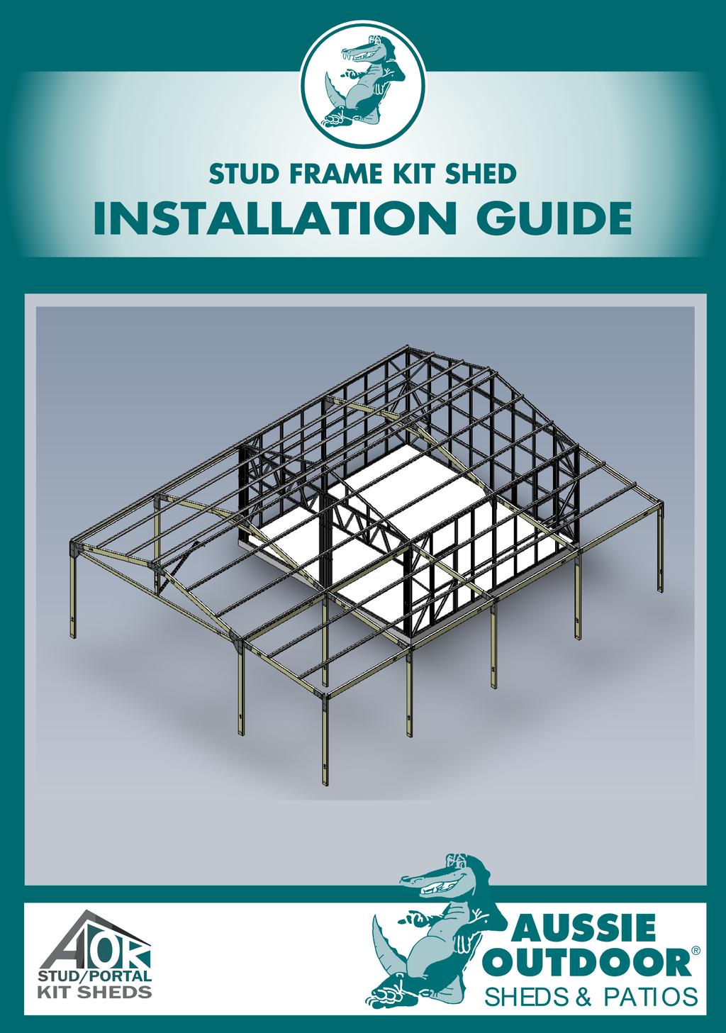
1 P a g e THIS IS A GENERIC MANUAL AND MAY NOT BE INDICATIVE OF YOUR CONSTRUCTION.
|
|
|
- Abner Hood
- 5 years ago
- Views:
Transcription
1 1 P a g e
2 INDEX SECTION DESCRIPTION PAGE 1 TOOLS REQUIRED 3 2 GENERAL PARTS IDENTIFICATION Structural Members Brackets Fasteners and Bolts Roof and Wall Cladding Gutters and Rainwater Other Optional Products Doors and Windows Flashings. 8 3 FRAME ASSEMBLY PROCEDURE Frame Assembly CONSTRUCTION GUIDE STEP 1 Laying out the Panels STEP 2 Standing up the Walls STEP 3 Installing Portal Rafters STEP 4 Installing Top Hats STEP 5 Finishing the Frame STEP 6 Installing the Rolladors STEP 7 Installing Head Flashings STEP 8 Roof and Wall Sheeting STEP 9 Barge Cap and Corner Flashing STEP 10 Installing the PA Door STEP 11 Installing the Gutter STEP 12 Installing the Ridge Cap STEP 13 Cleaning up GALLERY - FINISHED PROJECTS P a g e


3 TOOLS REQUIRED 1.0 Tools Required Impact Drill Hammer Drill Safety Switch Extension Cord Cordless Box Tape Measure Spirit Level Marker Pen Builders Square Tin Snips Hacksaw Rivet Gun Silicone Gun Step Ladder C - Clamps Socket Ratchet 12, 14 & 18mm Sockets 10mm Concrete Drill Bit Shifting Spanner Chalk/String Line 1/8 Drill Bit Phillips No.2 Driver Bit 5/16 Hex Head Driver 3 P a g e
4 GENERAL PARTS IDENTIFICATION 2.1 Structural Members C Section Purlins (Rafters, Beams and Columns) All purlins will be clearly labelled with Mark Numbers Top Hat 64 x 1.0mm 73 x 1.0mm Stud 76 x 1.0mm PLATE/NOG 75 x 1.0mm Stud, Plate & Nogging Sections (Modular Frames) 64 Top hats (Roof Purlins) All Framing will be clearly labelled with Mark Numbers 2.2 Brackets Apex Bracket Haunch Bracket Column Base General Purpose (Stud to Rafter no Awning) Bracket Haunch Bracket Haunch Bracket Haunch Bracket (Awning Col Awning Rafter) (Stud to Rafter with Awning) (Front Garaport Col to Rafter) (Mid Garaport - Col to Rafter) 4 P a g e

 (Roof Cladding) (Top")

")
 M12-30 Purlin Bolt")

 (Frame Hold")

5 GENERAL PARTS IDENTIFICATION 2.3 Fasteners and Bolts Hex Tek M6-50 Hex Roof Zip 12-14x20 Hex Tek (Wall Cladding) (Roof Cladding) (Top hats/frames) Wafer Tek M6-50 Poly Zip Pop Rivets M10-25 Bolt & Nut (Gutter Brackets/General Fixing) (Translucent Cladding) (Stop-ends/Gutters/Downpipes) (Stud Frame Panel Joins) M12-30 Purlin Bolt M12-30 Fascia Bolt M10-75 Masonry Bolt 28mm Galv Washer (Brackets/Columns/Rafters) (Awning/Carport Brackets) (Frame Hold Downs) (Frame Hold Downs) 2.4 Roof and Wall Cladding CORODEK (Colorbond/Zinc) TRIMCLAD (Colorbond/Zinc) POLYCARB - Translucent Sheet (Corodek/Trimclad) 5 P a g e


6 GENERAL PARTS IDENTIFICATION 2.5 Gutter and Rainwater 150 Big Front Quad 150 Big Front Quad Gutter Brackets Gutter Stop Ends (Colorbond/Zinc) (Colorbond/Zinc) Big M Square Big M Square Gutter Drop Gutter Stop Ends (Colorbond/Zinc) (Colorbond/Zinc) 90mm PVC down pipe Down Pipe Straps Roof & Gutter Silicone 2.6 Other Optional Products 300mm Rotary Vents Roof & Wall Insulation Vermin Proofing 6 P a g e


7 GENERAL PARTS IDENTIFICATION 2.7 Door & Windows Roll-a-doors 2.65m Wide x various Heights 820mm Wide PA Doors Pre-skinned and Bored Sliding Glass Doors 1800mm High x 2100mm Wide (Aluminium all Colorbond colours) Sliding Glass Windows 900mm High x 600/900/1370mm wide (Aluminium all Colorbond colours) PA Door Lock-sets Sliding Glass Door Lock-sets Butt Hinges Knob or Lever Sets 7 P a g e
8 GENERAL PARTS IDENTIFICATION 2.8 Flashings 8 P a g e
9 GENERAL PARTS IDENTIFICATION 9 P a g e

 with all")


.")
.")
10 Studs/Jambs Marks to BOTTOM FRAME ASSEMBLY PROCEDURE 3.1 Frame Assembly (Fig 1) (Fig 2) You will receive a large flat pack (Fig 1) with all the components required to finish the frame bundled together there will be several packs corresponding to each individual frame. Each individual member whether it be Plate, Nogging or Stud (Fig 2) will be identified on the left hand of the member (Fig 3). After the member identification, the Wall Frame is also identified (Fig 3). (Fig 3) Mark No Plate/Noggin/Heads Marks to the LEFT 10 P a g e
11 (Fig 4) FRAME ASSEMBLY PROCEDURE Using your detail frame drawings provided (Fig 5), you will find a drawing for each wall and truss. (Fig 5) All pieces are individually marked with part number. EG. Wb1 being the first and Wb3 being the third piece. Always use drawing marks on detail drawings to locate the member in frame and ensure correct orientation of member before assembly e.g. (Fig 5: Section A-A) Plates/Nogging (Horizontal members) ensure the mark numbers are to the LEFT side of the frame. (Fig 4) Studs (Vertical members) ensure the mark numbers are to the BOTTOM of the frame. (Fig 4) When constructing a wall place the bottom on its edge on your workbench/floor. Then begin to place/insert studs laying left to right. Ensure the screw dimples are aligned. Repeat this procedure until all studs are in place. Then slide the nogging and head members through the studs and ensure screw dimples are aligned. Position the top plate onto the frame and align screw dimples. Start to insert screws, ensuring the wall is square. Please ensure all service holes/utility holes are in line. If not, you are using the components in the incorrect location or rotation. 11 P a g e

12 CONSTRUCTION GUIDE STEP 1 - LAYING OUT PANELS a) Place all the wall panels around slab as per your design requirements, orientating the corner panels to ensure the diagonal bracing in the panels is positioned towards the corners. (Fig 6) (Fig 6) 12 P a g e

 Position truss stiffeners to the centre of the wall with the flanges facing")
 a) Stand gable walls and fix to side wall using 12-14x20 Teks.")

13 CONSTRUCTION GUIDE b) Fit the rafters haunch brackets in between side panels where rafters are required with (6) x M10x25 bolts while on the ground. Use M10x25 flange bolts top, middle and bottom and bolt wall panels together. (Fig 7) (Fig 7) c) Bolt half trusses and gable panels together while on the ground using M10x25 flanged bolts at verticals. Use M10x25 flange bolts top, middle and bottom and bolt all wall panels together d) Position truss stiffeners to the centre of the wall with the flanges facing upwards. Fix with 12-14x20 tek screws (Fig 8) e) Fix and screw full truss and truss stiffener to gable panels with 12-14x20 tek screws. STEP 2 - STANDING WALLS (Fig 8) a) Stand gable walls and fix to side wall using 12-14x20 Teks. b) Continue around the slab until all walls are stood and fixed together. c) Square all walls to the slab with a string line. Ensure that sheeting can extend past the slab by 40mm. d) Where rolladoor panels are located use a marking pen to mark hold down bolt holes, move frames back and pre-drill holes using 10mm masonary drill bit, ensure you have the recomended depth and blow out all the debris. Move frames back into position and re-check for sqareness. e) If the slab is uneven pack out underneath the panels to produce a straight line to the bottom plate of panels. 13 P a g e


14 CONSTRUCTION GUIDE f) **CRITICAL** Where panels meet at the corners they must be vertically plumb - BOTH of the corner panels. If required pack out underneath both panels at the corners and use a long spirit level to check verticles at corners are plumb. g) Using a 10mm masonary drill bit, drill through inner holes in bottom of frames (Fig 9) where holes are next to the verticle members in the panel, ensure you have the recomended depth of 90mm and blow out and remove all the debris. h) Install the M10x75mm masonary bolts with 30mm washers using a impact drill and socket driver. (Fig 10) (Fig 9) (Fig 10) 14 P a g e
 b) At this point you can choose to cut your Collar tie or not. Cut in Collar Tie (Fig 10a).")
 (Fig 10b) 6m spans - SF2050 (Fig 10c) 7.")
 Lift complete portal into position and bolt the portal into the haunch barackets using M12x30 flanged purlin bolts.")
15 STEP 3 - INSTALLING PORTAL RAFTERS CONSTRUCTION GUIDE a) While on the ground bolt together the apex bracket and rafter purlins using M12x30 flanged purlin bolts. (Fig 10) b) At this point you can choose to cut your Collar tie or not. Cut in Collar Tie (Fig 10a). Not cut in Collar tie (Fig 10b). Refer to Drawings for cut in details below (Fig 10c) (Fig 10d) (Fig 10e) for your Collar tie. (Fig 10a) (Fig 10b) 6m spans - SF2050 (Fig 10c) 7.5m spans - SF2550 (Fig 10d) 9m spans - SF3050 (Fig 10e) c) Bolt Collar tie using M12x30 flanged purlin bolts. Do not tighten fully d) Lift complete portal into position and bolt the portal into the haunch barackets using M12x30 flanged purlin bolts. e) Using a temporary prop adjust the height of the portal and sight along the ridge using a string line so the portal rafters and the end trusses are all level. (Fig 11) (Fig 11) 15 P a g e
 g) When portals are level with end trusses and the side walls are plumb use a impact drill with a socket drive to tighten all the bolts in the haunches, apex and collar tie.")
 To fit the apex top hats first mark 140mm down from the apex to bottom flange of top hat (Fig 14) and place temporary teks in both end trusses and all portals to stop")
16 CONSTRUCTION GUIDE f) Check the side walls are still plumb. Using a ratched tie or temporary brace (Fig 12) pull/push the side walls into plumb. (Fig 12) g) When portals are level with end trusses and the side walls are plumb use a impact drill with a socket drive to tighten all the bolts in the haunches, apex and collar tie. h) Fix (1) x 12-14x20 teks next to each purlin bolt in the brackets to ensure there is no 'slip' when roof is loaded with roof sheeting and top hats. Then remove the temporary bracing. STEP 4 - INSTALLING TOP HATS a) To fit the apex top hats first mark 140mm down from the apex to bottom flange of top hat (Fig 14) and place temporary teks in both end trusses and all portals to stop from sliding, let the tophat rest above this tek. At the gable ends the top hats should be flush with outside of gable frame. (Fig 13) (Fig 13) 16 P a g e
 (Fig 14) c) Using (2) x 12-14x20 teks fix tophats to trusses and portals in both sides of the top hat in the flanges.")
17 CONSTRUCTION GUIDE b) Fit the eaves top hats flush along external walls and have the remaining tophats spaced evenly between apex and eaves. (Fig 14) (Fig 14) c) Using (2) x 12-14x20 teks fix tophats to trusses and portals in both sides of the top hat in the flanges. d) Where top hats are lapped fix (4) x 12-14x20 teks to both ends of the lap and into both sides. e) Fit strap bracing to end bays starting from apex going to opposite diagonal corners of bays using 12-14x20 teks. f) If required the supplied bracing tensioners can be installed to tension up the stap and also to fine tune the building into square and plumb. STEP 5 - FINISHING THE FRAME a) The bottoms of rolladoor/sliding glass door and PA door opens will still have the bottom framing plates attached, these can now be removed with a hacksaw or tinsnips. b) Windows and sliding glass doors need to be installed at this stage. Place the pre-assembled windows or sliding glass doors into the openings from the outside and fix to the frame at the sides using wafer teks. c) Ensure the windows or sliding glass doors are level and even in the openings. 17 P a g e


 Head flashings need to trimmed to size, add the depth of the side flashings for the appropriate openings + 5mm + the opening width and cut to this length.")
18 STEP 6 - INSTALLING THE ROLLADOORS CONSTRUCTION GUIDE a) Install rolladoor fixing plates to rolladoor frames both sides using 12-14x20 teks (Fig 15). These are the backing plates to support the rollador angle brackets. b) Please use the installation instructions provided by your rolladoor manufacturer that comes with your rolladoors to ensure all warranties are protected. This is a propriety item and must be installed correctly or by a professional installer. (Fig 15) STEP 7 - INSTALLING HEAD FLASHINGS a) Before sheeting the walls all the rolladoor/window/pa door and sliding glass door head flashings must be installed. b) Head flashings need to trimmed to size, add the depth of the side flashings for the appropriate openings + 5mm + the opening width and cut to this length. c) Install the flashing flush with the bottom of top plate of the frame using wafer teks. (Fig 16), wall sheeting will be cut/slit around the head flashings when sheeting is installed. Section 2.8 will identify the appropriate flashings for your openings. (Fig 16) 18 P a g e


19 CONSTRUCTION GUIDE STEP 8 - ROOF AND WALL SHEETING SAFTEY NOTES Always wear saftey gloves when handling any type of metal sheeting. Never attempt to install metal sheeting in windy conditions. GENERAL NOTES Roof and wall sheets are best cut using tin snips or electric nibblers. NEVER USE ABRASIVE CUTTING DISCS as they will damage the coating and promote corrosion. Where possible cut sheets on the ground and always clean off any swarf and metal filings. Wall and roof sheets should be fixed at the recommended supported spacings. (Fig 17 & 18) (Fig 17) (Fig 18) 19 P a g e
 (Fig 19) All Roof sheeting should be turned up at the apex and turned down at the gutter using a shifting spanner, turnup tool or a piece of 4\"x2\" wood with a saw cut 25mm deep into the end")
20 CONSTRUCTION GUIDE Teks with neoprene washers should never be under or over tightened. (Fig 19) (Fig 19) All Roof sheeting should be turned up at the apex and turned down at the gutter using a shifting spanner, turnup tool or a piece of 4"x2" wood with a saw cut 25mm deep into the end along the 4" direction. (Fig 20) Turning up Trimclad Turning up Corodek (Fig 20) Roof and wall sheets are always laid into the prevailing wind and weather. (Fig 21) (Fig 21) 20 P a g e
 Ensure the wall sheet is at the right height under the roof sheet and passes the slab by 40mm. You may want to flick a chalk line along the slab to assist you in keeping the right height.")
 Using tin snips or electric nibbler cut in the openings and trim back the rake on the gable ends.")
21 CONSTRUCTION GUIDE WALL SHEETING a) Ensure the first and second sheet is plumb to the frame by using a long spirit level, then check every 2-3 sheets as you progress along the wall. b) Ensure the wall sheet is at the right height under the roof sheet and passes the slab by 40mm. You may want to flick a chalk line along the slab to assist you in keeping the right height. c) Remembering that wall sheeting is valley fixed with 10x16 Hex Teks, fix at top, bottom and all center noggings using the method to suit your sheet profile (Fig 17 & 18). d) Using tin snips or electric nibbler cut in the openings and trim back the rake on the gable ends. (Fig 22) (Fig 22) ROOF SHEETING a) Ensure your first sheet is square to the gable and positioned 50mm past wall sheet into the gutter. b) Remembering that roof sheeting is rib fixed with M6-50 roof zips, fix at eaves and the center top hats using the method to suit your sheet profile (Fig 17 & 18). c) DO NOT fix the roof sheet to the apex tophats as these will be fixed when installing the ridge cap. 21 P a g e
 At the ridge, place a plumb line from the apex of the shed and mark the barge cap along the line with a marker. Cut the barge capping along this line as shown in (Fig 23).")
22 STEP 9 - BARGE AND CORNER FLASHINGS CONSTRUCTION GUIDE a) Place the first barge capping along one side of the roof where the bottom end of the barge capping should finish level with the bottom end of the roof sheets. b) At the ridge, place a plumb line from the apex of the shed and mark the barge cap along the line with a marker. Cut the barge capping along this line as shown in (Fig 23). (Fig 23) c) Place the retuning barge from the apex underneather the first to produce a lap. (Fig 24) (Fig 24) d) Trim returning barge capping to the same length as the roof sheeting. e) Start fixing the barge capping from the bottom gutter end of the gable (Fig 25) on to wall and roof sheeting using 10x16 Teks. Use pop rivets provided to fix the apex lap. (Fig 25) 22 P a g e
23 CONSTRUCTION GUIDE f) Fit corner flashings up behind the barge capping (Fig 25) using 10x16 wall teks provided making sure to fit along the same screw line as wall sheets. STEP 10 - INSTALLING THE PA DOOR a) You can set door to open either to the left or right side. b) Fit hinges to door frame 200mm from top and bottom of PA door. c) Ensure even and adequate gap to top, bottom and sides of door. d) Door should be flush with outside of frame with pins of the hinges on the outside of frame opening. e) Fit side flashing to frame and cut to length, fix using pops provided. f) Swing the door closed, fit the lock and mark latch holes, then drill latch hole in frame through side flashing. g) Install the striker plate provided with the lockset, use fixings proved or 4mm pop rivets (not included in kit). h) Fix the PA Door jamb flashing to the door panel when the door is closed so the jamb flashing stops the door at the right position flush with frame (flashing type 1), use pop rivets or 12-14x20 teks. STEP 11 - INSTALLING THE GUTTER a) Cut holes for downpipe dropper at the desired location. b) Fix concealed gutter brackets at both ends of the shed and ensure there a fall of approx 10mm over the length of the shed, use the wafter teks privided. c) Run a string line along the bottom edge of the brackets and install the remaining gutter brackets on the ribs of the sheeting between 900mm mm apart. d) Avoid placing brackets at downpipe drops or within 300mm of gutter joins. e) Install the gutter drops and gutter stop ends to the gutter using pop rivets and roof and gutter silicon. f) Where gutter joins allow 200mm over lap and place two beads of roof and gutter silicon and join using pop rivets provided. g) Gutter length should be flush with outside of both ends of barge capping. h) Remove all plastic and lift the gutter onto the roll of the concealed gutter brackets. 23 P a g e
24 CONSTRUCTION GUIDE i) Carefully roll the gutter towards the rear of the bracket until it clips into place at the same time ensuring the gutter fits neatly against the barge capping at either end of the building. j) Snip/notch barge capping to produce a lap over the gutter ends and use pop rivets to fix to gutter stop ends. (Fig 25) STEP 12 - INSTALLING THE RIDGE CAPPING a) Fit the ridge capping in the direction of the prevailing wind. b) Seal the joints using roof and gutter silicon. c) Screw down ridge capping through roof sheeting into top hats using M6x50 hex roof zips with neoprene seals. STEP 13 - CLEANING UP a) Clear entire site of all loose screws, sheeting/flashing off cuts and rubbish. b) Use vacuum cleaner to rid bottom of stud frames of all debris. c) Wash down all roof and wall sheeting to remove all swarf and chalk marks. d) Sweep entire slab area and wash down and allow to dry. When dry use an appropriate silicon sealant to seal bottom of stud frame to concrete slab and allow to cure. 24 P a g e


25 GALLERY FINISHED PROJECTS SOME FINISHED PROJECTS 6.00m x x Gable Entry with 6m Garaport 9.00m x x Gable Entry 25 P a g e


26 GALLERY FINISHED PROJECTS Shows rolladoor - head flashing/side flashing and gutter for a side entry shed. (Notice downpipe dropper is back from corner) Shows how barge is notched and fixed to gutter 26 P a g e


27 GALLERY FINISHED PROJECTS Internal studs are useful for running electrical conduit. Shows internal sheet flashing neatly finishes against roof top hats. (Notice how corner flashing and gable skirt is notched against eaves fascia purlin) 27 P a g e
GABLE ROOF CARPORT RECOMMENDED INSTRUCTION MANUAL
 GABLE ROOF CARPORT RECOMMENDED INSTRUCTION MANUAL Table of Contents Introduction 2 Components 3 Step 1a Marking out the Perimeter of the Carport with Footing only 3 Step 2a Footing Set-Out for Concrete
DUTCH GABLE CARPORT RECOMMENDED INSTRUCTION MANUAL
 DUTCH GABLE CARPORT RECOMMENDED INSTRUCTION MANUAL Table of Contents Introduction 2 Components 3 Step 1a Marking out the Perimeter of the Carport with Footing only 4 Step 2a Footing Set-Out for Concrete
Safety Glasses Safety Gloves Ladders Measuring Tape Spirit Level String Line. Tin-Snips Rivet Gun Caulking Gun Silicone Socket Set
 BEFORE YOU START Carefully read these instructions and refer to them constantly during each stage of construction. If you do not have all the necessary tools or information, contact Stratco for advice.
STRATCO GABLE HOMESHED STRATCO GABLE HOMESHEDS STUBBIE INSTALLATION GUIDE
 STRATCO GABLE HOMESHED STRATCO GABLE HOMESHEDS STUBBIE INSTALLATION GUIDE INSTALL GUIDE BEFORE YOU START COUNCIL APPROVAL It is important that you have local council approval before building your Stratco
TRADITIONAL GABLE ATTACHED PATIO AND CARPORT. Your complete guide to building an ATTACHED Outback TRADITIONAL GABLE PATIO or CARPORT
 TRADITIONAL GABLE ATTACHED PATIO AND CARPORT STRATCO OUTBACK ASSEMBLY INSTRUCTIONS. Your complete guide to building an ATTACHED Outback TRADITIONAL GABLE PATIO or CARPORT BEFORE YOU START Carefully read
STEEL BUILDINGS RECOMMENDED INSTALLATION GUIDE
 STEEL BUILDINGS RECOMMENDED INSTALLATION GUIDE 3 TO 30 METRE SPAN FRAME FIRST METHOD SUPPLIED BY: Last update 2 May 2008 2008 FBHS (Aust) Pty Limited FBHS (Aust) Pty Limited ABN 83 126 232 504 trading
DUTCH GABLE FREESTANDING CARPORT
 DUTCH GABLE FREESTANDING CARPORT STRATCO OUTBACK ASSEMBLY INSTRUCTIONS. Your complete guide to building a FREESTANDING Outback DUTCH GABLE CARPORT BEFORE YOU START Carefully read these instructions. If
Stratco Sanctuary INSTALLATION BEFORE YOU START TOOLS REQUIRED GUIDE
 INSTALLATION GUIDE Stratco Sanctuary Verandahs, Patios and Carports BEFORE YOU START It is important to check with your Local Government Authority prior to the installation of your new Stratco Sanctuary
Ensure there is reasonable access for materials and working space, ensure the shed site is level and consider the disposal of run-off water.
 INSTALLATION GUIDE TM Flat Roof Homesheds THE POTTER BEFORE YOU START It is important to check your Local Government Authority requirements before the installation of your new Stratco Potter Flat Roof
INSTALLATION GUIDE. Flat Roof Homesheds TM. Onto Concrete BEFORE YOU START TOOLS REQUIRED
 INSTALLATION GUIDE Flat Roof Homesheds TM Onto Concrete BEFORE YOU START It is important to check your Local Government Authority requirements before the installation of your new Stratco Flat Roof Homeshed.
INSTALLATION GUIDE. Outback. Flat Attached BEFORE YOU START ADDITIONAL MATERIALS TOOLS REQUIRED. VERAnDAHS PATIOS CARPORTS
 INSTALLATION GUIDE Outback VERAnDAHS PATIOS CARPORTS Flat Attached BEFORE YOU START It is important to check your Local Government Authority requirements before the installation of your new Stratco Outback
OUTBACK FLAT ATTACHED VERANDAH PATIO CARPORT - INSTALLATION GUIDE BEFORE YOU START TOOLS REQUIRED ADDITIONAL MATERIALS
 BEFORE YOU START It is important to check your Local Government Authority requirements before the installation of your new Stratco Outback Flat Verandah. It is the builder s responsibility to ensure any
INSTALLATION GUIDE. Flat Roof Homesheds TM BEFORE YOU START TOOLS REQUIRED
 INSTALLATION GUIDE Flat Roof Homesheds TM BEFORE YOU START It is important to check your Local Government Authority requirements before the installation of your new Stratco Flat Roof Homeshed. Read these
INSTRUCTION MANUAL FOR MULTIBUILD VERTICAL CLAD QUAKER BARN WITH OR WITHOUT OUT MEZZANINE FLOOR UP TO 12 METRE SPAN
 INSTRUCTION MANUAL FOR MULTIBUILD VERTICAL CLAD QUAKER BARN WITH OR WITHOUT OUT MEZZANINE FLOOR UP TO 12 METRE SPAN SUPPLIED BY: LAST UPDATED March 11, 2003 2001 AG&S Building Systems, Sydney Australia
Gable HomeshedsTM INSTALLATION BEFORE YOU START TOOLS REQUIRED GUIDE LARGE SPAN. Council Approval. Before Starting
 INSTALLATION GUIDE Gable HomeshedsTM LARGE SPAN BEFORE YOU START Council Approval It is important to contact your local council before building your Stratco Gable Homeshed. You will have already received
STEEL BUILDINGS RECOMMENDED INSTALLATION GUIDE
 STEEL BUILDINGS RECOMMENDED INSTALLATION GUIDE 3 TO 30 METRE SPAN TILT UP METHOD SUPPLIED BY: Last update 19 September 2011 2011 FBHS (Aust) Pty Limited FBHS (Aust) Pty Limited ABN 83 126 232 504 trading
Blokes Shed INSTALLATION INSTRUCTIONS Custom Design & Build. Nationwide Delivery
 Blokes Shed 10 Year Guarantee On Sanders workmanship Made in NZ Using NZ timber supplies 40+ Years Experience In business since 1975 Professional Install Available NZ wide Nationwide Delivery Available
PINEHAVEN SHEDS Assembly Instructions FOR LEAN-TO SHEDS
 PINEHAVEN SHEDS Assembly Instructions FOR LEAN-TO SHEDS GARDEN PRODUCTS www.pinehavensheds.co.nz 5/16 hex drive bit, By asking about our products at your nearest DIY or gardening store www.pinehavensheds.co.nz
GLOSSARY OF TERMS SECTION 8
 GLOSSARY OF TERMS SECTION 8 Anchor Bolt Angle Base Plate Bay Blocking CCB Centerline Chord Cladding Clip Closure Strip An A-307 steel bolt embedded in the concrete footing to anchor the base plate of the
STEEL BUILDINGS RECOMMENDED INSTALLATION GUIDE
 STEEL BUILDINGS RECOMMENDED INSTALLATION GUIDE 3 TO 30 METRE SPAN FRAME FIRST METHOD SUPPLIED BY: Last update 19 September 2011 2011 FBHS (Aust) Pty Limited FBHS (Aust) Pty Limited ABN 83 126 232 504 trading
INSTALLATION GUIDE. Outback Clearspan Gable BEFORE YOU START ADDITIONAL MATERIALS ADDITIONAL MATERIALS WITH COOLDEK ROOFING
 INSTALLATION GUIDE Outback Clearspan Gable WITH COOLDEK ROOFING BEFORE YOU START It is important to check your Local Government Authority requirements before the installation of your new Stratco Outback
Dura-Lock Roof System
 DLR-14 Dura-Lock Roof System Assembly and Installation Instructions Read the instructions before starting the job. They explain the steps required to produce a finished product that will meet factory specifications.
E N G L I S H GARDEN SHED. Assembly Instructions. Suitable for Models WITH VARYING DEPTHS
 GARDEN SHED Assembly Instructions Suitable for Models 6' Wide 8' Wide 0' Wide WITH VARYING DEPTHS GI0003 November 0 INSTALLATION ADVICE It's Not That Difficult! The construction of your shed isn't as complicated
INSTALLATION INSTRUCTIONS LS X 12-2 X 7 1/2 FRAME LOAFING SHED
 INSTALLATION INSTRUCTIONS LS-30 30 X 12-2 X 7 1/2 FRAME ACTUAL FRAME BASE SIZE: 30 X 12-2 LOAFING SHED Our unique assembly process quickly transforms the individual pieces into a finished structure that
Deluxe Cabana INSTALLATION INSTRUCTIONS. INSTALLATION Deluxe INSTRUCTIONS Cabana
 INSTALLATION Deluxe INSTRUCTIONS Cabana 1 Deluxe Cabana 10 Year Guarantee On Sanders workmanship Made in NZ Using NZ timber supplies 40+ Years Experience In business since 1975 Professional Install Available
GIRTS ON BACK OF BUILDING
 GIRTS ON BACK OF BUILDING ALL GIRTS ARE 1 1/2 SQUARE TUBE. GIRT LENGTHS FOR 12, 20, 24, AND 30 WIDE BUILDINGS: ON 12 WIDE BUILDINGS GIRTS ARE 67 3/4 LONG ON 20 WIDE BUILDINGS GIRTS ARE 56 3/4 LONG ON 24
CLEARSPAN GABLE STRATCO OUTBACK ASSEMBLY INSTRUCTIONS. WITH GAZEBO END ATTACHED PATIO
 CLEARSPAN GABLE WITH GAZEBO END ATTACHED PATIO STRATCO OUTBACK ASSEMBLY INSTRUCTIONS. Your supplementary guide to building an ATTACHED CLEARSPAN GABLE VERANDAH or PATIO WITH GAZEBO END This set of instructions
Outback Gable CLEARSPAN ATTACHED
 It is important to check your Local Government Authority requirements before the installation of your new Stratco Outback Flat Verandah. It is the builderʼs responsibility to ensure any existing structure
MULTISPAN GABLE WITH HIP END ATTACHED PATIO
 MULTISPAN GABLE WITH HIP END ATTACHED PATIO STRATCO OUTBACK ASSEMBLY INSTRUCTIONS. Your supplementary guide to building an ATTACHED MULTISPAN GABLE VERANDAH or PATIO WITH HIP END This set of instructions
INSTALLATION INSTRUCTIONS LS X 12-2 X 7 1/2 FRAME LOAFING SHED
 INSTALLATION INSTRUCTIONS LS-24 24 X 12-2 X 7 1/2 FRAME ACTUAL FRAME BASE SIZE: 24 X 12-2 LOAFING SHED Our unique assembly process quickly transforms the individual pieces into a finished structure that
BUILDING GUIDE FOR MULTIBUILD ALL STEEL BUILDINGS 3 TO 30 METRE SPAN
 BUILDING GUIDE FOR MULTIBUILD ALL STEEL BUILDINGS 3 TO 30 METRE SPAN SUPPLIED BY: 26 Dobney Ave, Wagga Wagga. NSW. 2650 PH: 02 6925 5719, Fax 02 6925 2895 Email: sales@havashed.com.au, Web Address: www.havashed.com.au
INSTALLATION INSTRUCTIONS LS X 12-2 X 7 1/2 FRAME LOAFING SHED
 INSTALLATION INSTRUCTIONS LS-12 12 X 12-2 X 7 1/2 FRAME ACTUAL FRAME BASE SIZE: 12 X 12-2 LOAFING SHED Our unique assembly process quickly transforms the individual pieces into a finished structure that
GROWING BETTER THROUGH DESIGN. 6ft Lean-To LEAN-TO. Assembly Instructions 04/02
 GROWING BETTER THROUGH DESIGN 6ft Lean-To LEAN-TO Assembly Instructions 04/02 6ft Lean-To Greenhouse Base Plan Introduction/Tools/Contents / / Contents This is a copy of our Lean-To greenhouse base plan.
COMPONENTS OF THE CLICKFAST FASCIA AND GUTTER SYSTEM 5: INTERNAL MITRE
 INTRODUCING THE CLICKFAST FASCIA AND GUTTER SYSTEM The Clickfast Fascia and Gutter System was originally designed by Stratco and has proven to be the most successful fascia and gutter system in Australia
Insulated Corrugated. Patio Installation Guide. SupaCore Insulation Superior Thermal Performance. Colorbond Steel Roof & Ceiling. InsulRoof roof panel
 Using the slot on the Turn-up/Turn-down tool, place the tool into the steel sheeting InsulRoof roof panel Rivet fixing through flashing Insulated Corrugated Roof pan turned down - gutter en 100mm Gutter
INSTRUCTION MANUAL FOR MULTIBUILD AMERICAN BARN
 INSTRUCTION MANUAL FOR MULTIBUILD AMERICAN BARN SUPPLIED BY: LAST UPDATED April 26, 2006 2001 AS&G Building Systems AMERICAN BARN The American Barn uses similar components to other steel frame buildings.
UNIVERSAL INSTALLATION INSTRUCTIONS FOR CARPORTS
 UNIVERSAL INSTALLATION INSTRUCTIONS FOR CARPORTS FRAME SIZES: WIDTH: 10, 12, 14, 16, 18, 20, 24, AND 30 ON CENTER FRAME SPACING: 4, 4 1/2, AND 5 FRAME LENGTH: 4 ON CENTER 20-2, 4 1/2 ON CENTER 18 AND 5
UNIVERSAL ASSEMBLY INSTRUCTIONS FOR VERSATUBE GARAGE BUILDINGS
 UNIVERSAL ASSEMBLY INSTRUCTIONS FOR VERSATUBE GARAGE BUILDINGS SINGLE DOOR GARAGE AVAILABLE IN 12, 20, 24 AND 30 WIDTHS DOUBLE DOOR GARAGE AVAILABLE IN 24 AND 30 WIDTHS Our unique assembly process quickly
Clopay Models 835/837 Sliding Door System Installation Guide
 Clopay Models 835/837 Sliding Door System Installation Guide The aim of this instruction is to guide you through the process of construction and fitting of Sliding Doors. Due to the number of sizes available
FLAT ROOF CARPORT RECOMMENDED INSTRUCTION MANUAL
 FLAT ROOF CARPORT RECOMMENDED INSTRUCTION MANUAL Table of Contents Introduction... 2 Components... 3 Step 1 Marking out the Perimeter of the Carport... 3 Step 2a Footing Set-Out for Concrete Block Pad
Greenhouse Assembly Instructions
 Greenhouse Assembly Instructions Our Help Line provides support and advice to customers of Summer Garden Buildings after ordering. For advice before you buy you can phone us free 7 days a week on 0800
CURVED ROOF ASSEMBLY INSTRUCTIONS ATTACHED VERANDAH. Your supplementary guide to building an ATTACHED CURVED ROOF VERANDAH or PATIO BEFORE YOU START
 ROOF ATTACHED VERANDAH ASSEMBLY INSTRUCTIONS Your supplementary guide to building an ATTACHED ROOF VERANDAH or PATIO This set of instructions should be used in conjunction with the Stratco instruction
UNIVERSAL ASSEMBLY INSTRUCTIONS FOR VERTICALLY SHEETED GARAGE BUILDINGS BUILDING WIDTHS: 12, 20, 24, AND 30
 UNIVERSAL ASSEMBLY INSTRUCTIONS FOR VERTICALLY SHEETED GARAGE BUILDINGS BUILDING WIDTHS: 12, 20, 24, AND 30 SINGLE DOOR GARAGE AVAILABLE IN 12, 20, 24 AND 30 WIDTHS DOUBLE DOOR GARAGE AVAILABLE IN 24 AND
Gardman Lean-to Greenhouse Assembly Instructions
 Page 1 Gardman Lean-to Greenhouse Assembly Instructions Our Help Line provides support and advice to customers of Summer Garden Buildings after ordering. For advice before you buy you can phone us free
7 X 10 X 6 SHELTER 7 X 16 X 6 SHELTER 12 X 10 X 6 SHELTER 12 X 16 X 6 SHELTER
 ASSEMBLY INSTRUCTIONS FOR 7 X 10 X 6 AND 7 X 16 X 6 ATV SPORT SHELTER ACTUAL FRAME SIZES: 7 X 9-1 1/2 X 6 AND 7 X 13-7 1/2 X 6 AND 12 X 10 X 6 AND 12 X 16 X 6 ATV SPORT SHELTER ACTUAL FRAME SIZES: 12 X
Installation Guidelines
 Page 1 Tools You ll Need 4 ft. Carpenter s level Chalk line (to mark U channel locations) Cordless drill/nut driver Caulking gun Chop saw with a metal cutting blade on it (required to make accurate and
Installation Guidelines
 Page 1 Tools You ll Need 4 ft. Carpenter s level Chalk line (to mark U channel locations) Cordless drill/nut driver Caulking gun Chop saw with a metal cutting blade on it (required to make accurate and
CARPORT INSTALLATION INSTRUCTIONS FOR 4 1/2 ON CENTER FRAMES
 CARPORT INSTALLATION INSTRUCTIONS FOR 4 1/2 ON CENTER FRAMES FRAME SIZES: WIDTH: 12, 14, 18, 20, 24, AND 30 ON CENTER FRAME SPACING: 4 1/2 FRAME LENGTH: 18 EAVE HEIGHTS: START AT 7 TO 12 1/2. Our unique
INSTALLATION INSTRUCTIONS SUBURBAN SERIES CARPORT 25 X 20 X 6 LENGTH CAN BE EXTENDED IN 4 1/2 INCREMENTS HEIGHT CAN BE EXTENDED IN 1 INCREMENTS
 INSTALLATION INSTRUCTIONS SUBURBAN SERIES CARPORT 25 X 20 X 6 LENGTH CAN BE EXTENDED IN 4 1/2 INCREMENTS HEIGHT CAN BE EXTENDED IN 1 INCREMENTS BASIC FRAME SIZES (NO EXTENSIONS): 25-1/2 X 18' x 6 EAVE
Installation Guide Simplicity Alfresco. V1.9 Lu070318
 0333 305 5272 www.canoports.co.uk Installation Guide Simplicity Alfresco V1.9 Lu070318 Tools Required Below is a list of tools that you will require to install your the Simplicity Alfresco System. Cordless
SteelChief Installation Instructions for pre-assembled panel form sheds GABLE ROOF
 SteelChief Installation Instructions for pre-assembled panel form sheds GABLE ROOF Please read fully before commencing work...any queries will be promptly answered, contact theboss@steelchief.com.aui MPORTANT
Level, Pliers, 3/8" Electric Drill, Carpenters Square, Tape Measure, Metal Hack Saw, Silicone Caulking, Screw Drivers (Regular & Phillips)
") Delta Door Canopy Installation Instructions Recommended Tools: Before You Begin: Level, Pliers, 3/8" Electric Drill, Carpenters Square, Tape Measure, Metal Hack Saw, Silicone Caulking, Screw Drivers (Regular
Delta Door Canopy Installation Instructions Recommended Tools: Before You Begin: Level, Pliers, 3/8" Electric Drill, Carpenters Square, Tape Measure, Metal Hack Saw, Silicone Caulking, Screw Drivers (Regular
Potting Store Assembly Instructions
 Before assembly We recommend that time is taken to read the instructions before starting assembly, then follow the easy step by step guide. The instruction sheet is only a guide to the assembly. Certain
ASSEMBLY INSTRUCTIONS GG77. BASE SIZE: 2.190m x 2.020m
 ASSEMBLY INSTRUCTIONS GG77 BASE SIZE: 2.190m x 2.020m CONGRATULATIONS ON PURCHASING A DURATUF GUARDIAN SHED. BEFORE YOU BEGIN THE ASSEMBLY PLEASE NOTE SOME IMPORTANT POINTS: BEFORE YOU START: Read all
CARPORT INSTALLATION INSTRUCTIONS FOR 4 1/2 ON CENTER FRAMES
 CARPORT INSTALLATION INSTRUCTIONS FOR 4 1/2 ON CENTER FRAMES WIDTH: 10, 12, 14, 16, 18, 20, 24, AND 30 ON CENTER FRAME SPACING: 4 1/2 FRAME LENGTH: 18 EAVE HEIGHTS: START AT 7 TO 12 1/2. FRAME SIZES: Our
Installation Manual. This installation is for the Odyssey H1800 Series Ventilation System.
 Installation Manual This installation is for the Odyssey H1800 Series Ventilation System. This installation is limited to roofs with pitches between 3 and 35. This instruction assumes that there is a power
Sliding Door Kit
 YOU MUST READ THIS DOCUMENT BEFORE YOU BEGIN TO ASSEMBLE THE DOOR KIT. Thank you for purchasing this GrowSpan door kit. When properly assembled and maintained, this product will provide years of reliable
ROOF FRAMING INFORMATION BATTEN INSTALLATION CORONA SHAKE INSTALLATION ACCESSORY INSTALLATION ESTIMATING DATA GENERAL INFORMATION
 ROOF FRAMING INFORMATION BATTEN INSTALLATION CORONA SHAKE INSTALLATION ACCESSORY INSTALLATION ESTIMATING DATA GENERAL INFORMATION ROOF FRAMING INFORMATION It is the responsibility or roofers, building
ASSEMBLY INSTRUCTIONS
 Quality Built In ASSEMBLY INSTRUCTIONS MK3 BASE SIZE 3380mm x 1715mm ASSEMBLY INSTRUCTIONS Tools Required: Drill Drill Bit 3.5mm Drill Bit 6mm (for clear roof panel only) Hex Drive 5/16 Riveter Hammer
IDAHO ASSEMBLY INSTRUCTIONS. BASE SIZE: 1.800m x 1.200m
 IDAHO ASSEMBLY INSTRUCTIONS BASE SIZE: 1.800m x 1.200m IDAHO Tools Required: Battery Drill Riveter Hammer Tape Measure Ladder Skillsaw Level Square Drive Bit No.2 3/8 Hex Drive Bit 8mm Hex Drive Bit Drill
ASSEMBLY INSTRUCTIONS SS2520. BASE SIZE: 2.520m x 2.020m
 ASSEMBLY INSTRUCTIONS SS50 BASE SIZE:.50m x.00m CONGRATULATIONS ON PURCHASING A SMART STORE SHED. BEFORE YOU BEGIN THE ASSEMBLY PLEASE NOTE SOME IMPORTANT POINTS: BEFORE YOU START: Read all instructions
NEVADA ASSEMBLY INSTRUCTIONS
 NEVADA ASSEMBLY INSTRUCTIONS BASE SIZE: 2.700m x 1.500m NEVADA Tools Required: Battery Drill Riveter Hammer Tape Measure Ladder Skillsaw Level Screwdriver - Flat 3/8 Hex Drive bit 8mm Hex Drive bit Drill
This installation guide has been created to assist in constructing a Liniar conservatory roof from a kit format.
 1.00 - Introduction This installation guide has been created to assist in constructing a Liniar conservatory roof from a kit format. Please note, each roof has been individually designed to meet specific
Ledger Board Lean-to Instruction Manual
 Ledger Board Lean-to Instruction Manual for 18 x 24 2 x 8 covers Our unique assembly process quickly transforms the individual pieces into a finished structure that will give you a lifetime of service.
 SUPREME WALL GARDEN ASSEMBLY INSTRUCTIONS 24/08/16 www.hallsgreenhouses.com Please refer to website for the most up to date instructions. SAFETY WARNING 1. Always wear protective glasses, shoes, gloves
Taurean Sectional Garage Door INSTALLATION INSTRUCTIONS
 BEFORE YOU BEGIN MAKE SURE THESE INSTRUCTIONS ARE READ AND UNDERSTOOD COMPLETELY. THESE INSTRUCTIONS ARE INTENDED FOR PROFESSIONAL GARAGE DOOR INSTALLERS. ALL REFERENCES ARE TAKEN FROM THE INSIDE LOOKING
Roof Only Lean-to Instruction Manual
 Roof Only Lean-to Instruction Manual for 10 x 20 2 x 8 /10 6 covers Our unique assembly process quickly transforms the individual pieces into a finished structure that will give you a lifetime of service.
Installation Manual. Last Updated 4 February, Postal PO Box 932 Bayswater VIC
 Installation Manual Last Updated 4 February, 2013 Part 1: Provided Material The Panel Expandable Foam Sealing Strip Barge Capping Z-Fascia Structural Screws Timber: 3/8 head size Metal: 5/16 head size
CARPORT INSTALLATION INSTRUCTIONS FOR 4 1/2 ON CENTER FRAMES
 CARPORT INSTALLATION INSTRUCTIONS FOR 4 1/2 ON CENTER FRAMES FRAME SIZES: WIDTH: 10, 12, 14, 18, 20, 24, AND 30 ON CENTER FRAME SPACING: 4 1/2 BASIC FRAME LENGTH: 18 CAN BE EXTENDED IN 4 1/2 INCREMENTS
LAS VEGAS PATIO COVER INSTALLATION INTSRUCTIONS
 STEP 8. Drill 2-5/8" dia. holes in the outer face of the ledger board spaced evenly (approximently 24" O.C.). Hoist the ledger board into place, centering it in front of the gutter. Anchor the inner face
12x12 Pavilion. Assembly Manual
 12x12 Pavilion Assembly Manual 12x12 Pavilion Assembly Manual Congratulations on purchasing your new Pavilion. Thank You for your purchase and Welcome to the YardCraft Famiy. This manual is designed to
ASSEMBLY INSTRUCTIONS SS2010. BASE SIZE: 2.020m x 1.020m
 ASSEMBLY INSTRUCTIONS SS010 BASE SIZE:.00m x 1.00m CONGRATULATIONS ON PURCHASING A SMART STORE SHED. BEFORE YOU BEGIN THE ASSEMBLY PLEASE NOTE SOME IMPORTANT POINTS: BEFORE YOU START: Read all instructions
ASSEMBLY INSTRUCTIONS FOR VERSATUBE VERTICALLY SHEETED 2 x3 & 2 x4 CARPORTS WIDTHS: 12, 16, 20, 24, 30, 36 & 40 4 & 5 ON CENTER FRAMES
 ASSEMBLY INSTRUCTIONS FOR VERSATUBE VERTICALLY SHEETED 2 x3 & 2 x4 CARPORTS WIDTHS: 12, 16, 20, 24, 30, 36 & 40 4 & 5 ON CENTER FRAMES Our unique assembly process quickly transforms the individual pieces
Ledger Board Lean-to Instruction Manual
 Ledger Board Lean-to Instruction Manual for 18 x 24 2 x 8 /12 6 covers ROOF ONLY ROOF WITH GABLES 2-SIDED FRAME ONLY 2-SIDED WITH GABLES Our unique assembly process quickly transforms the individual pieces
Assembly Book. 10' x 12' the Cambridge II. revised June 13, 2014
 Assembly Book revised June 13, 2014 the Cambridge II 10' x 12' Manufactured by Reynolds Building Systems, Inc. 205 Arlington Drive Greenville, PA 16125 724-646-3775 This manual is copyrighted. Under the
YUKON PATIO COVER INSTALLATION INSTRUCTIONS
 YUKON PATIO COVER INSTALLATION INSTRUCTIONS Before You Begin: Consult your local building department for any required permits You may be required to obtain a building permit for this structure. Contact
S H E D A S S E M B L Y I N S T R U C T I O N S
 T I T A N R A N G E S H E D A S S E M B L Y I N S T R U C T I O N S 8 X 10 ft Approx = 2550 x 3140 cm COMPONENT LIST Component illustrations are given as a visual guide only and are not in proportion PART
W L. Standard Sizes: 2.125m underside of gutters m total height m roof m roof m roof.
 H Standard Sizes: H 2.125m underside of gutters. 2.280m total height. L L 5.450m roof. 6.050m roof. 7.250m roof. W W 3.000m roof/2.640m between posts. 3.600m roof/3.240m between posts. 5.400m roof/5.040m
Best Barns USA. Regency Deluxe. 8' x 12' Assembly Book. revised February 15, 2017
 Best Barns USA Assembly Book revised February 15, 2017 Regency Deluxe 8' x 12' Manufactured by Reynolds Building Systems, Inc. 205 Arlington Drive, Greenville, PA 16125 This manual is copyrighted. Under
ASSEMBLY INSTRUCTIONS GL75. BASE SIZE: 2.190m x 1.520m
 ASSEMBLY INSTRUCTIONS GL75 BASE SIZE: 2.190m x 1.520m CONGRATULATIONS ON PURCHASING A DURATUF GUARDIAN SHED. BEFORE YOU BEGIN THE ASSEMBLY PLEASE NOTE SOME IMPORTANT POINTS: BEFORE YOU START: Read all
16ft Polytunnel Assembly Instructions
 CONTENTS Section Page 1. FOUNDATION TUBES: Option A Ground Anchor Plates 3 2. FOUNDATION TUBES: Option B Concreted Foundation Tubes 5 3. STEEL FRAME ASSEMBLY & INSTALLATION 6 4. CROP BARS 8 5. TIMBER END
Sliding Door Kit
 YOU MUST READ THIS DOCUMENT BEFORE YOU BEGIN TO ASSEMBLE THE DOOR KIT. Thank you for purchasing this GrowSpan door kit. When properly assembled and maintained, this product will provide years of reliable
UNIVERSAL ASSEMBLY INSTRUCTIONS FOR VERSATUBE FRONTIER GARAGE BUILDINGS
 UNIVERSAL ASSEMBLY INSTRUCTIONS FOR VERSATUBE FRONTIER GARAGE BUILDINGS Our unique assembly process quickly transforms the individual pieces into a finished structure that will give you years of service.
CONSERVATORY ROOF INSTALLATION GUIDE Issue
 CONSERVATORY ROOF INSTALLATION GUIDE Issue 3 CONTENTS 1. Statements 2. General assemblies 3. Victorian / Edwardian roof installation 4. Jack rafter installation 5. P-shaped roof installation 6. Lean-to
Summer Greenhouses 6x8 GREENHOUSE 185. Assembly instructions for the. 6x8 Aluminium Greenhouse 185 PLEASE READ ALL INSTRUCTIONS BEFORE PROCEEDING
 Summer Greenhouses 6x8 GREENHOUSE 185 Assembly instructions for the 6x8 Aluminium Greenhouse 185 PLEASE READ ALL INSTRUCTIONS BEFORE PROCEEDING Summer Greenhouses phone us free on 0800 9777 828 CONTENTS
Best Barns USA Assembly Book
 Best Barns USA Assembly Book Revised September 19, 2016 the Meadowbrook-R 16' x 10' Manufactured by Reynolds Building Systems, Inc. 205 Arlington Drive Greenville, PA 16125 724-646-3775 This manual is
Installation guide. Step-by-step instructions
 Installation guide Step-by-step instructions Contents Tools Required to Install p1 Screws & Fixings p2 Injection Moulded Solid Components p3 Components p4 Georgian Hips & Ancillaries p5 Fixing Eaves Beam
OZARK DOOR CANOPY ASSEMBLY INSTRUCTIONS
 OZARK DOOR CANOPY ASSEMBLY INSTRUCTIONS Recommended Tools: Level, Pliers, 3/8" Electric Drill, Carpenters Square, Tape Measure, Metal Hack Saw, Silicone Caulking, Screw Drivers (Regular & Phillips) Before
ASSEMBLY INSTRUCTIONS FOR VERTICALLY SHEETED CARPORTS
 ASSEMBLY INSTRUCTIONS FOR VERTICALLY SHEETED CARPORTS WIDTHS: 12, 20 & 24 5 ON CENTER FRAMES Our unique assembly process quickly transforms the individual pieces into a finished structure that will give
10 Wide AMATEUR CEDAR GREENHOUSE
 10 Wide AMATEUR CEDAR GREENHOUSE ASSEMBLY INSTRUCTIONS Our Help Line provides support and advice to customers of Summer Greenhouses after ordering. For advice before you buy phone us free 7 days a week
Retractable Screen Installation Instructions For Vinyl and Aluminum Clad and Wood In-Swing Hinged Doors (See separate instructions for sliding doors)
") Retractable Screen Installation Instructions For Vinyl and Aluminum Clad and Wood In-Swing Hinged Doors (See separate instructions for sliding doors) IMPORTANT: Please read before you begin. Table of Contents
Retractable Screen Installation Instructions For Vinyl and Aluminum Clad and Wood In-Swing Hinged Doors (See separate instructions for sliding doors) IMPORTANT: Please read before you begin. Table of Contents
Installation Guide. Step 3. Valley Flashing. Step 7. Transition Flashings and Accessories. Step 6. Hip and Ridge Installation
 Step 7. Transition s and Accessories Step 3. Valley Step 6. Hip and Ridge Installation Step 2. Rake Trim Step 5. Installing the Shingles Step 1. Eave Starter Installation Step 4. Endwall s Installation
Shed Assembly Instructions
 Shed Kit Contents The shed kit includes all the parts needed to assemble your shed except for tools and fasteners such as screws and nails. The various pieces are pre-cut and many are marked to indicate
SHED PACK Step 1: Choose your shed type.
 SHED PACK Step 1: Choose your shed type. Industrial Shed Open FarmShed Shed Pack / Types of Sheds Drawing # S0104.A001 Hanger Shed =DISCLAIMER= Please read and agree to Purlin Brackets Terms and Conditions
Shingle Installation Guide
 Installation Guide Roof Framing Information Installation Installation Accessory Installation Estimating Data General Information Roof Framing Information It is the responsibility or roofers, building contractors
Sunhouse. Assembly Manual
 Sunhouse Assembly Manual Thank you for your purchase of this sunhouse. Sunhouse Assembly Manual This manual is designed to simplify the assembly process, however we recommend having an experienced carpenter
HANDI-MATE SHED BEFORE YOU START INSTALL GUIDE HINGED DOOR HANDI-MATE INSTALLATION GUIDE PRIOR TO INSTALLATION
 HANDI-MATE SHED HINGED DOOR HANDI-MATE INSTALLATION GUIDE INSTALL GUIDE BEFORE YOU START PRIOR TO INSTALLATION It is important that you contact your local government authority to determine if building
GrowSpan Estate Pro I Greenhouse
 GrowSpan Estate Pro I Greenhouse Photo may show a different but similar model. 2016 Growers Supply All Rights Reserved. Reproduction is prohibited without permission. STK# DIMENSIONS 104564 11'-8" W x
Installation Guide Simplicity 6. v3.5 lu171117
 0845 869 6006 www.canoports.co.uk Installation Guide Simplicity 6 v3.5 lu171117 Tools Required Below is a list of tools that you will require to install the Simplicity 6 Canopy or Carport. Cordless Drill
10x10 Trellis Pergola
 0x0 Trellis Pergola ASSEMBLY GUIDE Ver.-007 Table of Contents PAGE 0x0 Trellis Pergola Introduction & Overview...................................................... Pergola Materials Overview..............................................................