Absco Highlander Shed Model: 3045HK
|
|
|
- Anissa Rhoda Terry
- 5 years ago
- Views:
Transcription


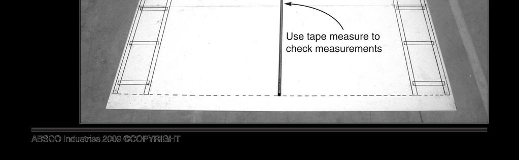
1 FOR CONSTRUCTION IN NON-CYCLONIC AREAS WIND RATING: W33N (N2) FRONT: 3.0 m SIDE: 4.48m HEIGHT: 2.3 m CONCRETE SLAB 300mm 4580mm CONCRETE WHEN LAYING YOUR CONCRETE SLAB, ENSURE THERE IS A REBATED EDGE 25mm DEEP AROUND THE PERIMETER 00mm REBATED EDGE CONCRETE SLAB THIS WILL HELP WATER EGRESS FROM THE BASE OF THE SHED 75mm WIDE REBATE We thank you for choosing an Australian made shed. For further assistance please visit our detailed instructional video library at At ABSCO Industries we are always looking to be number ONE, so please let us know what you think of our instructions. Feedback makes us better. feedback@absco.com.au PAGE


2 GENERAL Before commencing any assembly, read through these instructions in detail to gain a thorough understanding of assembly methods and associated details. Unpack the carton and carefully identify and check off all the parts against the parts described and illustrated on the following pages. Local Authority approval must be obtained prior to construction of the shed. Once you have selected your site you will need to lodge a site plan to your local council SITE PREPARATION The site for the shed must be level. An uneven surface may result in misalignment of parts. It is recommended that the shed be set on a 00mm rebated concrete slab and anchored down appropriately (refer to last page for details). A flat slab with a chamfered edge can be used but will not result in optimum results. IF USING A REBATE ENSURE ALL FRAME UPRIGHTS ARE TRIMMED 25mm. Anchor sets are not supplied as standard items with this product as some customers wish to use their own anchoring systems. TOOLS REQUIRED OPTIONAL Normal: 3mm Normal: 4mm & 0mm Masonry: 0mm A NOTE ON SAFETY Some parts may have sharp edges. It is advisable to wear gloves when handling these items and safety glasses if drilling holes. Sensible shoes are highly recommended. Do not erect your shed in windy conditions, ensure that the shed is securely anchored to a solid foundation immediately after construction is completed. It is highly recommended to erect the shed with two or more people. PAGE 2
.")


3 SPLIT SHEET H39 INTO H39B SHEETS This ABSCO products comes with a perforated sheet (H39) that is designed to be split into two smaller sheets (H39B). In circumstances when the sheet is not pre-split please refer to the below guidelines. SPLITTING SHEET H39 QTY COMPONENT DESCRIPTION PART No. QTY COMPONENT DESCRIPTION PART No. STEEL SHEET 2034mm X 773mm H39 2 = STEEL SHEET 2034mm X 329mm H39B THESE SHEETS HAVE SHARP EDGES. ONCE SEPARATED PLEASE USE APPROPRIATE FOOT AND HAND PROTECTION WHEN HANDLING. In order to split the sheet lay it on the ground and lift and fold one end until the perforations have cleanly snapped. Discard the middle piece as scrap when convenient. Fold the scrap piece in half 2-3 times and throw in bin. SCRAP SCRAP SCRAP SCRAP SCRAP SCRAP SCRAP SCRAP CHECK SHEET FOR PERFORATIONS FOLD FIRST SECTION OF SHEET UNTIL FREE FOLD MIDDLE SECTION OF SHEET UNTIL FREE DISCARD MIDDLE PIECE PAGE 3
4 COMPONENTS PACKING LIST - CHECK OFF ALL COMPONENTS MAIN PACK CARTON (PACK OF 3) QTY COMPONENT DESCRIPTION PART No. CHECK QTY COMPONENT DESCRIPTION PART No. CHECK 2 STEEL SHEET 974mm X 773mm H26 2 GABLE L/H L=475mm 6L STEEL SHEET 974mm X 773mm F 2 GABLE R/H L=475mm 6R 2 STEEL SHEET 546mm X 773mm 45A 2 BRACE L= 393mm 3A 2 STEEL SHEET 2034mm X 329mm H39B RIDGE 2 BEAM 97BL L = 52mm 2 STEEL SHEET 974mm X 7mm H37 RIDGE 2 BEAM 97BR L = 52mm STEEL SHEET 2034mm X 73mm H32 3 RIDGE BEAM JOINER L: 450mm (7.7") ZARSP STEEL SHEET 2034mm X 73mm H33 FITTINGS & ACCESSORIES PACKET (SEE PAGES 6 & 7) SET (SEE PAGES 4 & 5) ALL SHEETS HAVE PART NO.S LOCATED ON LOWER RIGHT OR UPPER LEFT CORNER OF COLORED SIDE AS SHOWN Part No. Here PAGE 4
5 COMPONENTS PACKING LIST - (CONT.) CHECK OFF ALL COMPONENTS SET QTY COMPONENT DESCRIPTION PART No. CHECK QTY COMPONENT DESCRIPTION PART No. CHECK L = 26.5mm 54A 54AL L = 26.5mm 54A 54AR L = 26.5mm 54C 54CL L = 26.5mm 54C 54CR 3 L = 26.5mm 54B 54BL 3 L = 26.5mm 54B 54BR 4 L = 2253mm 60B 60BL 4 L = 2253mm 60B 60BR 4 8C L = 26.5mm 8CL 4 8C L = 26.5mm 8CR 3 L = 26.5mm 8D 8DL 3 L = 26.5mm 8D 8DR L = 496.5mm 77B 77BL L = 496.5mm 77B 77BR 77C L = 496.5mm 77CL 77C L = 496.5mm 77CR 8A L = 496.5mm 8AL 8A L = 496.5mm 8AR PAGE 5
6 COMPONENTS PACKING LIST - (CONT.) CHECK OFF ALL COMPONENTS SET (CONTINUED) QTY COMPONENT DESCRIPTION PART No. CHECK QTY COMPONENT DESCRIPTION PART No. CHECK 2 L = 773mm 58C 58C Part No. Here JAMB L= 788mm 90B 4 L = 55mm 63A 63A 2 Part No. Here JAMB L= 20mm 9A L = 788mm 79B 79B Part No. Here JAMB L= 537mm 93L 2 L = 329mm 8M 8M Part No. Here JAMB L= 797mm 93R 3 HC WITH HINGES L = 974mm HC 3 Part No. Here JAMB L= 2034mm HJ 2 L = 974mm HC2 HC2 Part No. Here JAMB L= 2034mm HJ2 4 87A LIP TRIM L= 546mm 87A Part No. Here JAMB L= 974mm HJ3 PAGE 6
7 COMPONENTS PACKING LIST - (CONT.) CHECK OFF ALL COMPONENTS FITTINGS & ACCESSORIES PACKET CONTENTS QTY COMPONENT DESCRIPTION PART No. CHECK QTY COMPONENT DESCRIPTION PART No. CHECK DOUBLE DOOR KIT (SEE BELOW) SINGLE DOOR KIT (SEE OVER) ASSEMBLY INSTRUCTION MANUAL 2 CAP GABLE L: 70mm 4A 24 SELF DRILLING HEX HEAD TEK SCREWS (NO HOLE REQUIRED) 3 DOOR STRAP L: 65mm 2A 3mm (0.2") DRILL BIT RIDGE CAP JOINER 98A HEX TEK SCREW DRIVER BIT RIDGE 5 PLATES RBP PHILLIPS HEAD DRIVER 9 JOINER L= 200mm (7.9") CSJ 4 JAMB L= 75mm 93B DOUBLE DOOR KIT PACKET CONTENTS 3 DOOR PADBOLT 22A 2 DOOR PADBOLT HASP SELF TAPPING SCREWS PACKET CONTAINING /6 ROUND HEAD BOLTS & NYLOCK NUTS 2 3/6 COUNTERSUNK SCREWS & NUTS x 8mm BLIND POP RIVETS PAGE 7
8 COMPONENTS PACKING LIST - (CONT.) CHECK OFF ALL COMPONENTS SINGLE DOOR KIT PACKET CONTENTS DOOR PADBOLT 22A DOOR PADBOLT HASP SELF TAPPING SCREWS PACKET CONTAINING x 8mm BLIND POP RIVETS 2 3/6 COUNTERSUNK SCREWS & NUTS MAIN PACK CARTON (PACK 2 OF 3) 5 STEEL SHEET 2034mm X 773mm H C L = 954mm 8 STEEL SHEET 2034mm X 773mm H3 HIGH-PORTAL PACK (SEE BELOW) C482 L = 482mm HIGH-PORTAL FRAME ACCESSORIES 4 KNEE PLATE 8 0mm DYNABOLT 4 APEX PLATE 300 6mm TEK SCREWS 4 MULTI PURPOSE BRACKET PAGE 8
9 COMPONENTS PACKING LIST - (CONT.) CHECK OFF ALL COMPONENTS HIGH-FRONT FRAME PACK (PACK 3 OF 3) QTY COMPONENT DESCRIPTION PART No. CHECK QTY COMPONENT DESCRIPTION PART No. CHECK C K0285 L = 2300mm L = 285mm N C0240 L = 2070mm L = 240mm C C000 L = 2034mm L = 00mm M484 L = 484mm 99A HAT= 2290mm SMALL TRIANGULAR PLATE 4 HAT= 350mm 99B 50 SELF DRILLING 6mm TEK SCREWS 0 MULTI PURPOSE BRACKET 6 0mm DYNABOLTS PAGE 9

 x 3mm (0.2\") (2 PER A SIDE) HOLES TO SECURE SECTIONS TOGETHER.")
. Push the CSJ into the channel until you here a 'click'.")
10 FOR JOINING SPLICED S NOTE: THE TEXT MARKED ON ALL PARTS MUST BE SHOWN ON THE SAME SIDE AS EACH OTHER. = = = = CSJ JOIN>> <<JOIN JOIN>> = = J JOIN>> SJ STEP. Position the channels and the CSJ joiner channel so the center of the CSJ is in line with the end of each channel to be joined together. STEP 2. Join the first channel to the CSJ by inserting the center of the CSJ (on an angle) to the end of the channel where the JOIN>> text is marked. Push down one side of the CSJ until you hear a 'click'. = = JOIN>> <<JOIN JOIN>> = <<JOIN = DRILL 4mm (0.6") x 3mm (0.2") (2 PER A SIDE) HOLES TO SECURE SECTIONS TOGETHER. (THESE SCREWS MAY HAVE TO BE TEMPORARILY REMOVED AND REPLACED DURING LATER ASSEMBLY) STEP 3. Join the second channel to the CSJ by positioning the <<JOIN end of the channel at the center of the CSJ (on an angle). Push the CSJ into the channel until you here a 'click'. FINISHED The joined channels should now look like the picture above with the CSJ positioned equally inside of the joined channels. PUSH QTY = 0pcs. CSJ PUSH CSJ CSJ CSJ HIGH-SIDE CSJ LOW-SIDE 20mm (0.79") CSJ 5mm (0.59") PAGE 0

11 STEP. PRE-ASSEMBLY OF SPLICED S NOTE: JOIN TOGETHER 32 X SECTIONS USING 6 X JOINERS (PART CSJ) 4 X 60BR 4 X 60BL 3 X 54BR 3 X 54BL X 54CR X 54CL NOTE: SOME S HAVE HOLES IN THEM - YOU WILL NEED TO RE-DRILL HOLES ON ANY WHERE THE CSJ JOINING COVERS HOLES ON THE S YOU ARE CONNECTING 4 X 8CR 4 X 8CL X 54AR X 54AL 3 X 8DR 3 X 8DL 54CL 2253mm (88.7") 60BL 60BR 8CL 54AL 8CR 54AR 54CR 54BL 54BR 8DL 8DR = = = = = = 4 x 60B 4 x 8C x 54A 3 x 54B x 54C 3 x 8D PAGE
12 STEP. PRE-ASSEMBLY OF SPLICED S NOTE: JOIN TOGETHER 6 X SECTIONS USING 3 X JOINERS (PART CSJ) NOTE: SOME S HAVE HOLES IN THEM - YOU WILL NEED TO RE-DRILL HOLES ON ANY WHERE THE CSJ JOINING COVERS HOLES ON THE S YOU ARE CONNECTING 5 X 8AR 5 X 8AL X 77CR X 77CL 2993mm (7.8") 8AL 8AR 77CL 77CR 77BL 77BR = 5 x 8A = x 77C = x 77B X 77BR X 77BL PAGE 2


13 FOR JOINING SPLICED RIDGE BEAM STAGE : PUSH RIDGE BEAMS TOGETHER, MAKE SURE THERE IS A 50mm OVERLAP OF THE RIDGE CAP STAGE 2: INSERT RIDGE CAP JOINER INTO CONNECTED RIDGE CAPS. MAKE SURE JOINER HAS 225mm IN EACH RIDGE CAP. STAGE 3: TURN RIDGE CAP OVER AND MEASURE 250mm FROM THE END OF EACH RIDGE CAP. PLACE TEK SCREWS IN 50mm INCREMENTS FROM SAID END. REPEAT THIS PROCESS FOR THE OPPOSING HALF OF RIDGE BEAM PAGE 3
14 STEP 2. PRE-ASSEMBLY OF SPLICED RIDGE BEAM 2x REQUIRED QTY. = TEK SCREW DRIVER BIT QTY. = 8 SELF DRILLING TEK SCREW QTY. = 2 RIDGE BEAM 52mm (45.4") PARTS 97BL & 97BR QTY. = PUSH PUSH PART ZARSP - 450mm (7.7") LONG 6mm (0.63") 97BR ZARSP 200mm (7.9") 250mm (9.8") 97BL 6mm (0.63") (PART 97B) 2253mm (88.7") OVERALL LENGTH THE TOP SECTIONS OF CAPPING WILL OVERLAP EACH OTHER AT THE JOIN BY 50mm (2.0"). PAGE 4
15 VIEW OF ROOF COMPONENTS 87A 60B 8C 45A 45A 45A 8C 45A 45A 45A 98A 45A 45A 87A 45A 45A 60B 45A 60B 97B 8C 4A 87A 45A NOTE: ALL PERIMETER S 8C & 60B NEED TO BE SHORTENED BY 6.5mm AS PER PAGE 20 4A 97B 60B 87A 8C PAGE 5

16 HC H37 63A 77C 8M H26 63A 93L H26 HJ H37 99A HC 99B HJ 8M NOTE: SOME COMPONENTS ARE IDENTICAL EXCEPT FOR PRE-PUNCHED HOLE LOCATIONS. TAKE CARE WHEN ASSEMBLING COMPONENTS, ENSURING THAT THE PART NUMBERS MARKED ON EACH COMPONENT MATCH THOSE NOTED IN EACH STAGE OF THESE. 6R 6L DOOR SHEET 725mm SINGLE 9A 6L 6R H39B 54B H30 H3 8D H3 H39B 54B H3 H3 H30 8D H30 H30 H3 8D H3 8A H3 H33 H3 90B HJ 79B H30 H32 54C 77B 54A LAY OUT ALL PARTS AS ILLUSTRATED TO FAMILARISE YOURSELF WITH COMPONENT IDENTIFICATION AND THEIR INTENDED LOCATIONS. HIGH-PORTAL FRAMES HIGHPFRONT FRAME 93R 54B HJ2 NOTE: ALL PERIMETER S 8D, 54C,54B & 54A NEED TO BE SHORTENED BY 6.5mm AS PER PAGE 20 HC2 2A 58C F 22A 58C HC HC2 HJ3 63A VIEW OF WALL COMPONENTS PAGE 6


17 ABSCO ASSEMBLY INTRODUCTION The snap-tite assembly system locks most perimeter channels to all roof and wall sheets without the need for tools and fasteners. SNAP T TE i SNAP T TE To pre-assemble the four wall panels and two roof panels, the perimeter channels are secured to the top and bottom of each panel using the snaptite system, as detailed on the following pages wherever you see the symbol. SNAP T TE i i HIGH SIDE PUSH HIGH SIDE HIGH SIDE HIGH SIDE PUSH After joining sheets together, position channel over one end of the sheets, gently tapping it over the snaptite lugs, working along the sheets to the other end. Position sheets on timbers, trestles or partly over edge of concrete slab. FASTENING SYMBOLS D PUSH HIGH SIDE Join components together by pre-drilling the holes first. Use one component as a template to mark where the holes are. Drill with 3mm drill bit. Join components together with one screw at this location only, as some channel sections have extra holes that are not required for this model of garden shed Do not join components together at this location yet, as the screw may obstruct further assembly of other components Each perimeter channel must finish flush with the edges of the sheets. the snap-tite system allows adjustment for this process by simply tapping the channel along the sheets until each end is neatly flush. If you need to remove channels from the panels, pull the channel along the panel from opposing ends. You may need someone to help with this. 3mm POP RIVETS 4mm NUT & BOLT SET SELF DRILLING TEK SCREW FOR JOINING FRONT AND CENTRE FRAME COMPONENTS PAGE 7
18 JOINING WALL & ROOF PANELS THE 2253mm LONG PANELS NOW NEED TO BE JOINED TOGETHER, TO MAKE ONE CONTINUOUS PANEL, FOR EACH ROOF AND WALL SECTION. THE PERIMETER S WILL HAVE TO BE REDUCED IN LENGTH EQUAL TO THE AMOUNT OF THE OVERLAP, AS SHOWN BELOW TRIM THE PERIMETER S BY 6.5mm TO ALLOW EDGE RIBS OF THE SHEETING TO BE OVERLAPPED. OVERLAP THE PANELS AND SECURE WITH SCREWS AS SHOWN. REFER TO THE PANEL CONSTRUCTION SECTION OF THIS INSTRUCTION FOR FURTHER DETAILS, AND ENSURE THAT THE PANELS ARE NOT JOINED TOGETHER WITH PRE-PUNCHED HOLES INCORRECTLY POSITIONED. THE OVERALL LENGTH OF EACH PANEL SHOULD BE THE SAME LENGTH AS THE RIDGE BEAM, WHICH IS 4473mm. RIDGE BEAM/PANEL LENGTH = 2253 LESS CUT OFF SECTION = 6.5 NEW LENGTH = TWO PANELS JOINED: X 2 = 4473mm IT IS NOT CRITICAL THAT THE OVERALL LENGTH OF 4473mm IS EXACT, BUT TRY AND MAINTAIN THE LENGTH WITHIN 5mm. PAGE 8
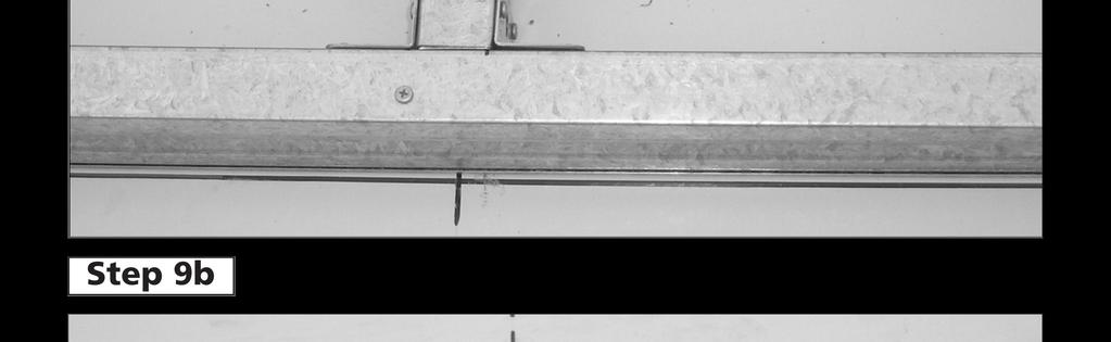
19 JOINING RIDGE BEAMS USING A HACKSAW, REMOVE ONE PROTRUDING SECTION OF EACH RIDGE BEAM. DO NOT CUT OFF THE PROTRUDING SECTION AT EACH END OF THE FULL LENGTH RIDGE BEAM THIS WILL ALLOW THE TWO SECTIONS TO BUTT UP NEATLY TO EACH OTHER. QTY. = QTY. = 8 QTY. = 2 TEK SCREW DRIVER BIT SELF DRILLING TEK SCREW RIDGE BEAM INSERT THE RIDGE BEAM SPLICE AT AN EQUAL DISTANCE INTO EACH RIDGE BEAM. USE A STRING LINE TO ENSURE THAT THE BEAM IS STRAIGHT, THEN SECURE WITH SELF DRILLING SCREWS AS SHOWN. A B QTY. = RIDGE BEAM SPLICE (PART RBS) (VERY TIGHT FIT, USE A HAMMER TO TAP INTO POSITION) C A B C C A B 4473mm OVERALL LENGTH SECURE THE CAP JOINER (PART 98A) AS SHOWN PAGE 9
 TO THE INSIDE FACE OF THE TOP (77B) INSIDE OF SHED PAGE")
20 . END PANEL ASSEMBLY 77B H30 H3 i SNAP T TE 8A H3 H30 i SNAP T TE OUTSIDE OF SHED TURN THE PANEL OVER. FIT THE TWO LARGE GABLES (6L & 6R) TO THE INSIDE FACE OF THE TOP (77B) INSIDE OF SHED PAGE 20
21 2. SIDE PANEL ASSEMBLY (Three Required) ONE REQUIRED SHEET TYPE H30 THIS END H30 H3 H3 H3 H30 H3 SHEET TYPE H30 IS A CORNER SHEET AND MUST BE ORIENTATED TOWARDS THE SHEDS CORNERS WHEN PANELS FINALLY JOINED AS PER PAGE 20. TWO REQUIRED SHEET TYPE H30 THIS END 54B i SNAP T TE 8D i SNAP T TE NOTE: BE CAREFUL WITH ORIENTATION. THESE PANELS MUST JOIN TOGETHER AS PER PAGE 20. ENSURE THAT 54B & 8D MATCH TO THEIR CORRESPONDING S WHEN CONNECTING TO CORRESPONDING PANEL SECTIONS. PAGE 2
 FITTED TO THIS END ONLY. i SNAP T TE 60B 87A i SNAP T TE 8C 2 x PRE-PUNCHED HOLES TO THIS END OF EACH SHEET WITH PART NO.")
22 3. ROOF PANEL ASSEMBLY (4 Required) 45A 45A 45A NOTE: TWO ROOF PANEL SECTIONS WILL HAVE PART (87A) FITTED TO THIS END ONLY. NOTE: TWO ROOF PANEL SECTIONS WILL HAVE PART (87A) FITTED TO THIS END ONLY. i SNAP T TE 60B 87A i SNAP T TE 8C 2 x PRE-PUNCHED HOLES TO THIS END OF EACH SHEET WITH PART NO. 8C FITTED 87A ONCE COMPLETED THERE WILL BE 4 SECTIONS WITH 87A LIP AT ONE END ONLY. PAGE 22

23 4. DOOR PANEL ASSEMBLY SIDE DOOR 58C (ONE REQUIRED) i SNAP T TE 974mm SINGLE DOOR SHEET (FULLY PRE-PUNCHED) F HC HC2 FRONT DOORS (TWO REQUIRED) 2A i SNAP T TE 58C NOTE: THESE SHEETS HAVE NOT BEEN PRE-PUNCHED H37 LOCATE THE NARROW PAN AT THIS END H26 PRE-DRILL DOOR SHEETS WITH A 3mm DRILL BIT USING THE PRE-PUNCHED COMPONENTS SHOWN AS TEMPLATES. i 63A SNAP T TE HC NOTE: FIT ONE DOOR WITH A (PART HC2) FIT THE OTHER DOOR WITH A JAMB (PART HJ3) 20mm FLANGE 2A i SNAP T TE 63A 20mm 5mm FLANGE 5mm PAGE 23


24 5. FRONT PANEL ASSEMBLY HJ HJ2 H32 H33 54A 54A HJ 90B HJ 90B i SNAP T TE 54A i SNAP T TE 90B 54A 79B 54C i SNAP T TE i SNAP T TE 79B 54A HJ2 HJ2 79B 54C 54C PAGE 24


25 6. DOOR PANEL ASSEMBLY A F 9A NOTE: Nuts and bolts (supplied) may be used instead of pop rivets (supplied) by simply enlarging the hinge hole sets in the jamb using a 4mm drill bit F NOTE: The two holes required to connect the padbolt hasp for each door have not been pre-punched, to allow for proper alignment. position each hasp centrally over the padbolt shaft, and secure with screws. The sheet metal screws supplied have the ability to self drill through the channel, use a continuous firm pressure and high drill speed and the screws will penetrate the sheet metal. If necessary a 3mm drill bit can be used. PAGE 25
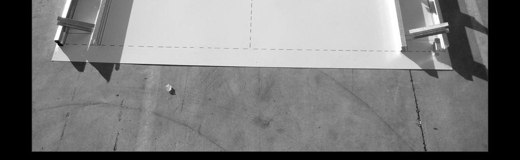
26 HIGH-PORTAL FRAME DETAILS REFER TO PAGE 4 FOR HIGH-PORTAL FRAME PARTS AND ACCESSORIES 80mm PART C482 PART C mm 80mm FRAME ASSEMBLY AN EASY WAY TO ENSURE THAT THE ANGLE AT THE TOP OF THE PORTAL FRAME IS CORRECT IS TO USE THE GABLE WALL PANEL AS A TEMPLATE TO LAY THE SECTIONS OUT. AS THE PORTAL FRAME FITS INSIDE THE WALLS, THE WIDTH OF THE FRAME WILL BE 40mm LESS THAN THE GABLE WALL PANEL. 2295mm 2950mm 2 x APEX PLATES NOTE: PLEASE REFER TO THE PHOTOS ON PAGES 4-48 FOR CLARITY X KNEE PLATE x KNEE PLATE 6R 6L NOTE: REFER TO THE FOLLOWING PAGE FOR FURTHER DETAILS. NOTE: IF YOU HAVE AN EDGE REBATE IN YOUR CONCRETE SLAB, YOU WILL HAVE TO CUT AN AMOUNT OFF THE BOTTOM OF THE FRAME LEGS EQUAL TO THE DEPTH OF THE REBATE. PAGE 26
27 x HIGH-PORTAL FRAME ASSEMBLY SECURE RIDGE PLATES TO APEX PLATES = x x 8 3. x x x 6 (REFER: PANEL CONSTRUCTION) 45mm TEK SCREW WALL PANEL WALL PANEL 2 CENTRE LINE SLAB/PORTAL FRAME/WALL PANELS PORTAL FRAME PAGE 27
28 8. HIGHLANDER HIGH-FRONT FRAME ASSEMBLY (SHEET of 2) 6mm SELF DRILLING TEK SCREWS USE JOIN PART NUMBERS C2300 C0240 ONLY TO FORM BOXED SECTIONS FIT THE S WHICH FORM THE BOXED SECTIONS TOGETHER WITH THE SMALLER EDGE NEATLY INSIDE THE LARGER EDGE. FASTEN WITH SCREWS AT 300mm SPACINGS WHERE POSSIBLE. REFER TO PAGE 7 FOR FRONT FRAME PARTS AND ACCESSORIES TRIANGULAR PLATE C2034 C0240 RIDGE PLATE M484 MULTI PURPOSE BRACKETS C2300 K0285 N2070 REFER TO THE FOLLOWING PAGE FOR FURTHER DETAILS. C000 PAGE 28
29 8. HIGHLANDER HIGH-FRONT FRAME ASSEMBLY (SHEET 2 of 2) FIT ONE 00mm SECTION (C000) TO BOX THE BASE OF EACH OUTSIDE LEG AS SHOWN. THESE WILL LATER BE USED FOR SECURING THE FRAME TO THE CONCRETE SLAB. SECURE THE SMALL TRIANGULAR PLATE TO THE EXTERIOR SIDE OF THE FRAME. SECURE THE RIDGE PLATE TO THE INTERIOR SIDE OF THE FRAME. 40mm ALL SECTIONS LAYOUT ALL SECTIONS AS SHOWN IN THE SAME MANNER AS THE PORTAL FRAME USE 6mm SELF DRILLING SCREWS JOIN ALL COMPONENTS TOGETHER WITH THREE SCREWS AT ALL CONNECTING POINTS ON BOTH SIDES OF THE FRAME NOTE: IF YOU HAVE AN EDGE REBATE IN YOUR CONCRETE SLAB, YOU WILL HAVE TO CUT AN AMOUNT OFF THE BOTTOM OF THE FRAME LEGS EQUAL TO THE DEPTH OF THE REBATE. PAGE 29
30 9. FRONT PANEL ASSEMBLY i SNAP T TE 77C 93R H39 93L 8M i SNAP T TE HJ i SNAP T TE H39 HJ 8M i SNAP T TE PRE-PUNCHED HOLES TO OUTSIDE EDGE 6R 6L NOTE: THE OUTER EDGE OF THE FRONT PANEL SHOULD PROTRUDE 20mm PAST THE OUTER EDGE OF THE FRONT FRAME FOR CORNER LAPPING OF SIDE WALL PANELS. (FIG. B) NOTE: WHEN THIS FRONT PANEL IS FASTENED TO THE FRONT FRAME, ALL THREE JAMBS SHOULD FINISH FLUSH WITH THE EDGE OF THE FRONT FRAME, THUS FORMING A WEATHERPROOF REBATE FOR THE DOORS. (FIG. A) LEFT HAND FRONT FRAME RIGHT HAND FRONT FRAME FIG. A FIG. A FIG. B FIG. B PAGE 30
31 FRONT AND CENTRE FRAME TO SLAB DETAILS FIG 8A RECOMMENDED SLAB DIMENSIONS mm x 300mm EXTERNAL WALL DIMENSIONS mm x 3000mm INTERNAL WALL DIMENSIONS mm x 2960mm CONCRETE SLAB 4580mm x 300mm CENTRE OF PORTAL FRAMES CENTRE FRAME UPRIGHT CENTRE FRAME UPRIGHT MULTI PURPOSE BRACKETS 80mm LONG FRONT FRAME CORNER UPRIGHT SLAB EDGE - SECURE MULTI PURPOSE BRACKETS TO UPRIGHTS USING SELF DRILLING SCREWS - MOVE FRAMES INTO POSITION, MARK AND DRILL HOLES IN SLAB USING 0mm MASONARY DRILL BIT - SECURE FRAMES TO SLAB WITH DYNABOLTS PAGE 3
32 0. PANEL CONSTRUCTION NOTE: TAKE CARE TO ENSURE THAT BOTH FRONT AND REAR WALL PANELS ARE NOT POSITIONED UPSIDE DOWN. THE TOP OF EACH PANEL IS PRE-PUNCHED FOR ATTACHING ROOF SHEETS, THE BOTTOM S ARE NOT. SIDE WALL PANEL S FIT INTO THE NOTCHED FRONT AND REAR WALL PANEL S USE 6mm SELF DRILLING TEK SCREWS TO SECURE WALLS TO INTERNAL FRAMES PRE-PUNCHED TO MATCH RIDGE BEAM HOLES. SHEETING PRE-PUNCHED THIS END TO FOR CONNECTION TO FRONT AND REAR WALLS PAGE 32


 FROM THE TOP WALL TO THE UNDERSIDE OF THE RIDGE")
33 . ROOF CONSTRUCTION SLIDE THE ROOF PANELS INTO POSITION, AND SECURE WITH ONE SCREW AT EACH CORNER ONLY AT THIS STAGE. NOTE: HOLES THAT SHOW THIS SYMBOL D REQUIRE PRE-DRILLED HOLES. 2 INSIDE VIEW D D SECURE EACH RIDGE BEAM TO EACH RIDGE PLATE WITH 4 X 6mm SELF DRILLING TEK SCREWS. SECURE RIDGE BEAM TO GABLE SECTIONS WITH TWO SCREWS AT EACH END. THE RIDGE BEAM (97B) SHOULD FINISH FLUSH WITH THE OUTSIDE OF THE GABLES (6L & 6R) D D D X4 PRE-DRILL 3 2 X GABLE BRACE (3A) D D INSIDE VIEW AFTER THE ROOF PANELS HAVE BEEN SECURED, FIT TWO GABLE BRACES (3A) FROM THE TOP WALL TO THE UNDERSIDE OF THE RIDGE BEAM AT 45 DEGREES AS SHOWN. ALIGN THE ROOF PANELS WITH THE WALL PANELS AND SECURE EACH CORNER AT PRE-PUNCHED LOCATIONS. -WARNING- DO NOT CLIMB ON TO OR WALK ON THE ROOF. PAGE 33
34 2. DOOR INSTALLATION - SECURE FRONT DOORS TO THE FRONT PANEL IN SAME MANNER AS THE SIDE DOOR WAS FITTED 99A FASTEN TO SLAB DRILL 2mm HOLE CENTRALLY TO PICK UP PADBOLT 93B USE THE 75mm JAMB SECTIONS (93B) AS PADBOLT SUPPORTS. DRILL AND SECURE THESE SECTIONS TO THE TOP AND BOTTOM OF THE DOOR, THEN FIT PADBOLTS. 99B FIT DOOR BRACES (99B) TO EACH DOOR AS SHOWN BY FASTENING AT EACH END, THEN DRILLING REMAINDER HOLES FROM THE INSIDE FACE OF EACH DOOR AND SECURING WITH SCREWS FROM THE OUTSIDE FACE OF EACH DOOR. PAGE 34

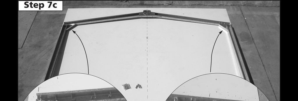
35 FINAL CONSTRUCTION. SECURE THE ROOF PANELS TO THE WALL PANELS AS SHOWN. 2. AFTER THE ROOF PANELS HAVE BEEN FULLY SECURED TO THE WALL PANELS, SECURE THE ROOF PANELS TO THE INTERNAL FRAMES WITH SELF DRILLING TEK SCREWS. 3. SECURE THE PORTAL FRAMES TO THE RIDGE BEAM AS DETAILED IN THE PREVIOUS PAGE. D D D D D D BEND THE TOP AND BOTTOM FLANGES AS SHOWN, THEN HOOK THE BOTTOM FLANGES UNDER THE TOP AND SCREW THE TOP FLANGES FOR BOTH AS SHOWN GABLE CAPS D D D D D D D D D D D D D D ANCHORING OF SHED LOCATION OF 6 CONCRETE ANCHORS - EACH ANCHOR CONSISTS OF ONE NUT, BOLT, DYNABOLT AND STEEL ANGLE - DRILL A 0mm HOLE INTO THE WALL SHEET BOLT & NUT STEEL ANGLE WALL SHEET SLAB - DRILL A 0mm HOLE INTO THE CONCRETE DYNABOLT PAGE 35
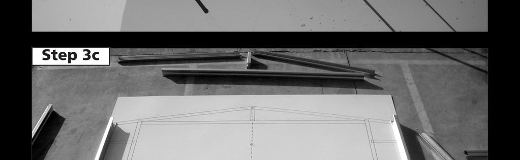
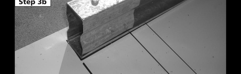
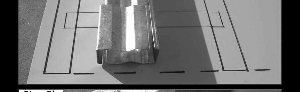
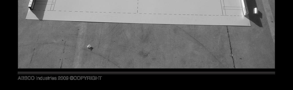
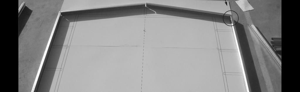
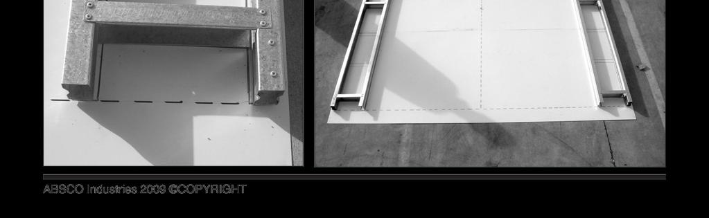
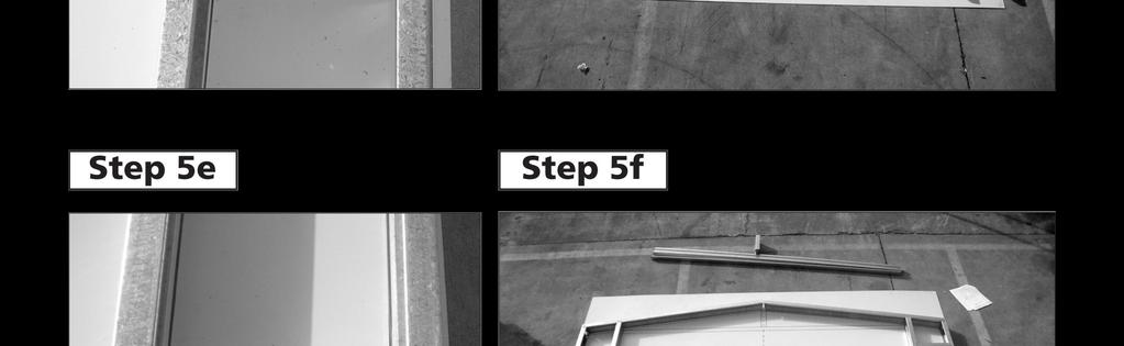
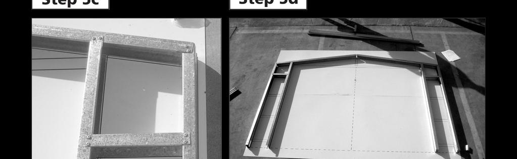
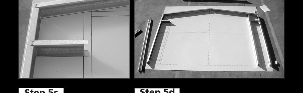
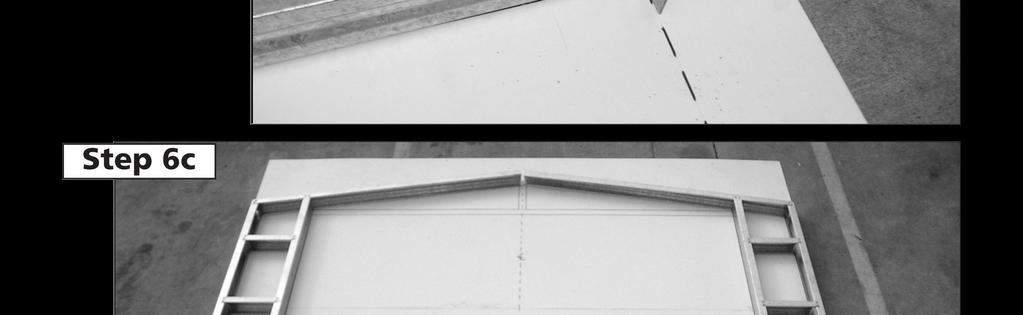
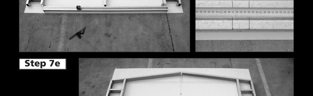
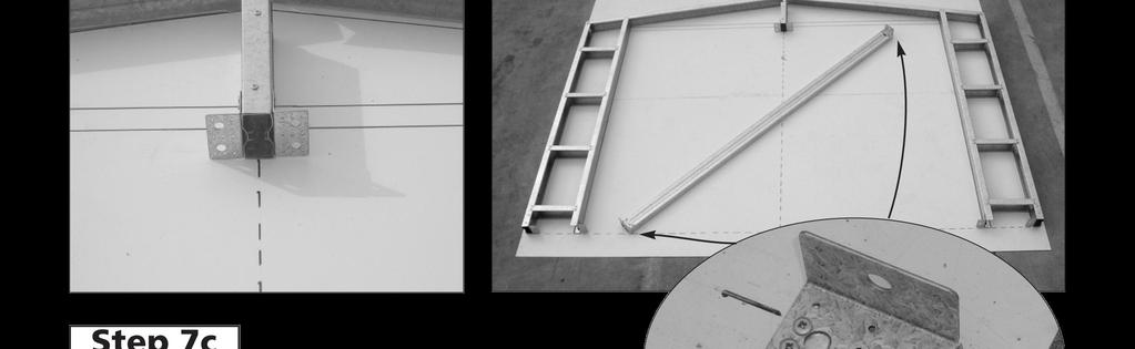
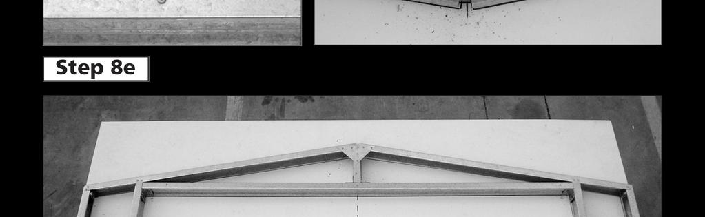
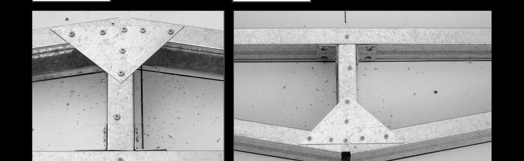
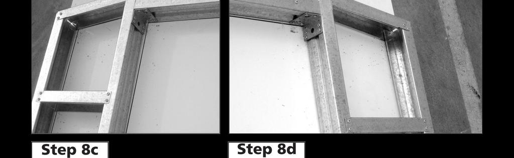
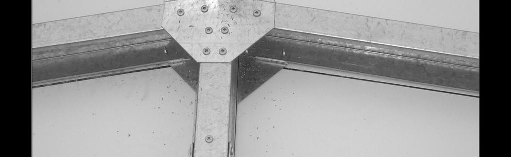
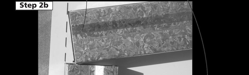
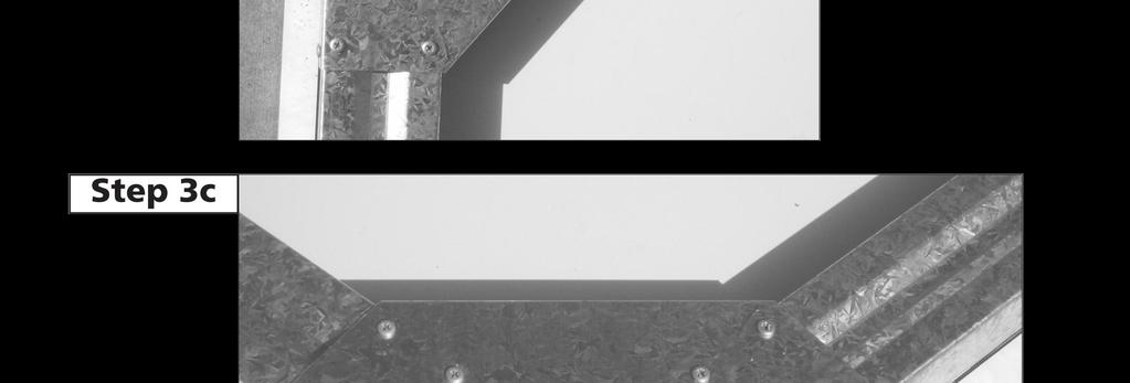
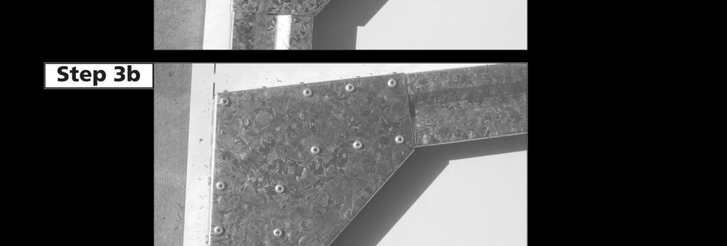
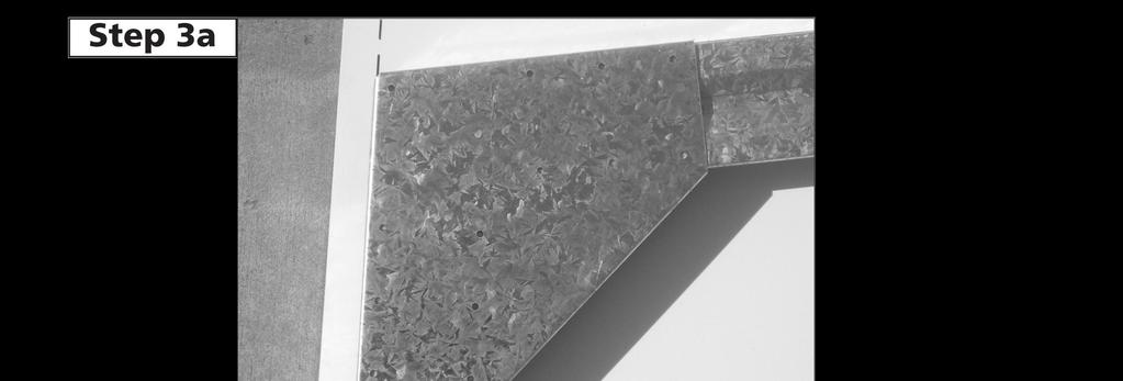
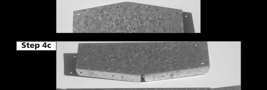
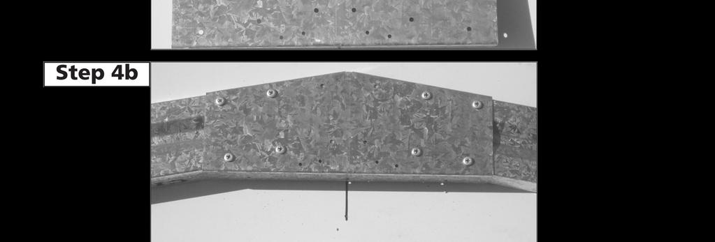
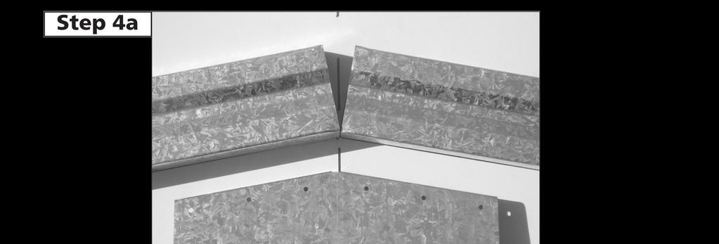
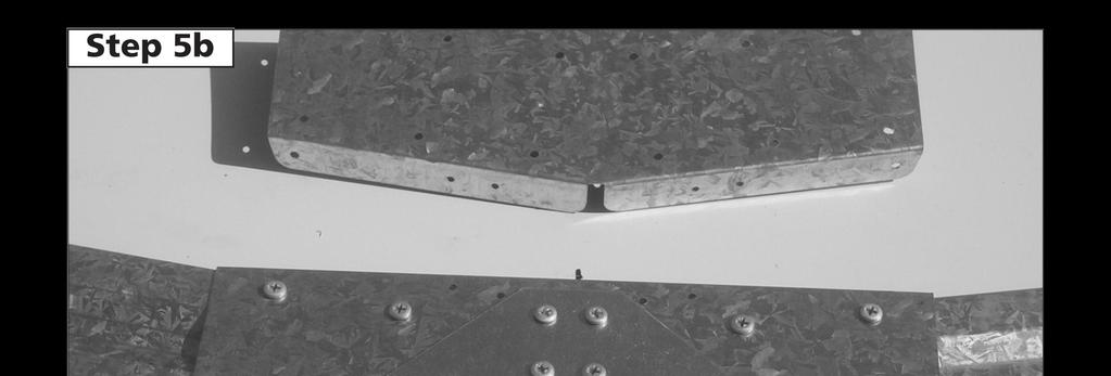
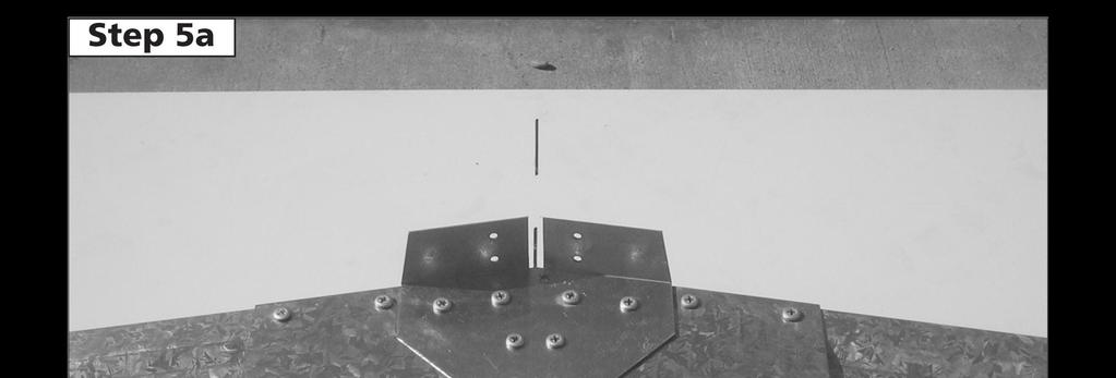
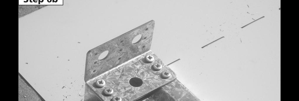
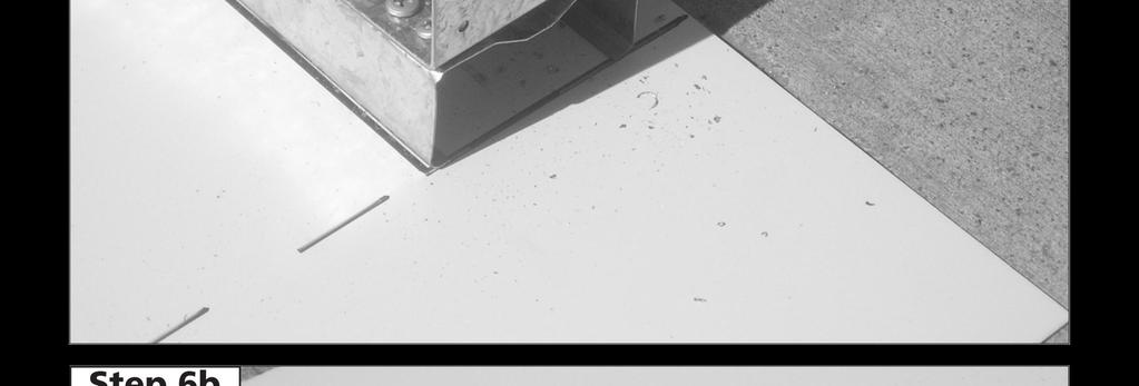
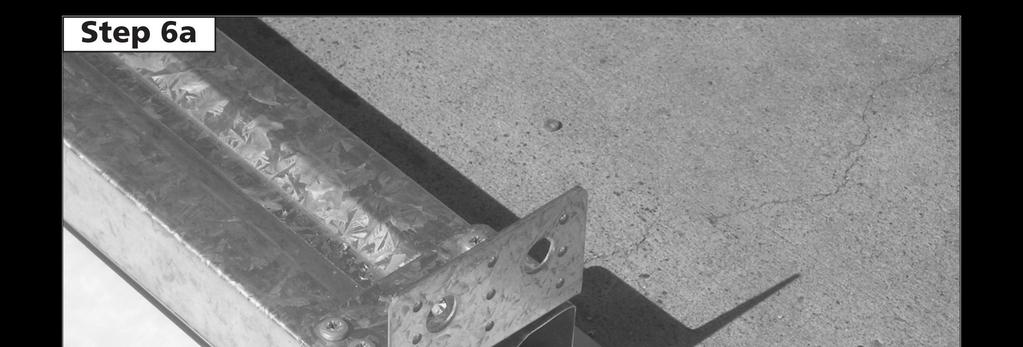
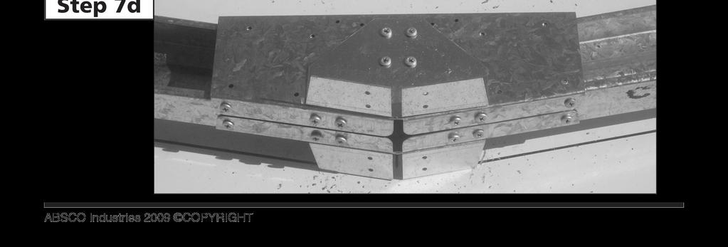
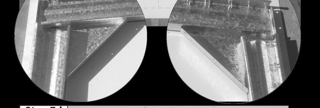
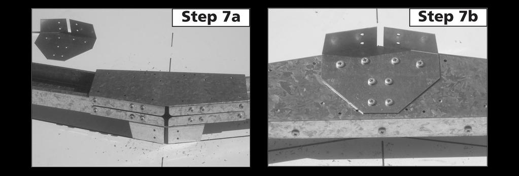
36 ABSCO HIGHLANDER SHED: HIGH-FRONT FRAME ASSEMBLY SUPPORT PHOTOGRAPHS STEP A, B, C: Draw pattern on concrete (Ref, pg 22). STEP 2: STEP 3A, B, C: STEP 4A, B: STEP 5A, B, C, D, E, F: STEP 6A, B, C: STEP 7A, B, C, D, E: STEP 8A, B, C, D, E: Understand where components are to be positioned Join C000 to C2034 Join C2034 to M484 Join K0285 to C2034 & N2070 Fit multi purpose bracket Assemble the C0240 & C2300 sections Join all sections together STEP 9A, B: Turn frame over and repeat steps 4 to 8 STEP 0: Fully Assembled front frame PAGE 36
37 PAGE 37

38 PAGE 38
39 PAGE 39


40 PAGE 40

41 PAGE 4


42 PAGE 42


43 PAGE 43

44 PAGE 44


45 PAGE 45


46 PAGE 46
47 ABSCO HIGH-PORTAL FRAME ASSEMBLY ASSEMBLY SUPPORT PHOTOGRAPHS STEP A, B, C: Draw pattern on concrete, in accordance with the dimensions detailed in the assembly instruction. STEP 2A, B, C: Understand where components are to be positioned STEP 3A, B, C: Join C482 C954 STEP 4A, B, C: Join C482 to C482 STEP 5A, B: STEP 6A, B: Secure ridge plate (RBP) Secure multi purpose brackets STEP 7A, B, C, D: Turn frame over, repeat steps 4,5 PAGE 47

48 PAGE 48


49 PAGE 49


50 PAGE 50

51 PAGE 5


52 PAGE 52

53 PAGE 53

54 PAGE 54
55 AUSTRALIA PRODUCT WARRANTY AGAINST DEFECTS Congratulations on your purchase of an ABSCO SHED ABSCO SHEDS, including garden sheds, garden beds, aviaries, storage units, garages, awnings and carports are made using high quality Australian made steel. We are pleased to advise we warrant that the steel coating will not rust, crack, flake peel or blister for 30 years from date of purchase, when installed within Australia. This warranty does not apply to surface deterioration of panels caused by Swarf (Tiny particles of steel debris left from cutting, grinding or drilling operations) that has not been removed after building construction, or as a result of contact with damp soil, chemicals, fertilisers or other corrosive substances. This warranty covers any Absco product used for normal domestic use and installed in accordance with the installation instructions. The warranty does NOT cover Damage caused by storms, wind, rain snow or poor foundations. This warranty does NOT cover ABSCO products installed in severe coastal, industrial or other highly corrosive environments. The warranty does not cover fasteners (screws, nuts, bolts, rivets, hasps or sliding padbolts). The warranty is limited to replacement and delivery of components and does not include any labour or installation costs. The benefits given by the warranty are in addition to your other rights and remedies under a law in relation to the goods or services to which the warranty relates. The warranty applies to the exclusion of all other representations, guarantees or warranties express or implied, our goods come with guarantees that cannot be excluded under the Australian consumer law and is not transferable. You are entitled to a replacement or refund for a major failure and for compensation for any other foreseeable loss or damage. You are also entitled to have the goods repaired or replaced if the goods fail to be of an acceptable quality and the failure does not amount to a major failure. For further information go to Please retain a proof of purchase (sales docket or invoice) or register your warranty within 30 days of purchase here: In the unlikely event a warranty claim is made, it must be supported by photographic evidence and details of the defect, including component part numbers, together with proof of purchase documentation (or on-line registration of purchase) and forwarded to the address below. Upon receipt of the warranty claim, the Customer Service Manager will contact you within three business days to advise you of the assessment outcome of the claim, which may include your expenses incurred in making the claim. THE CUSTOMER SERVICE MANAGER, ABSCO INDUSTRIES, PO BOX 9 ACACIA RIDGE QLD AUSTRALIA 40 PHONE: FAX: warranty@absco.com.au Issued 0 January 203 P a g e
56 ABSCO SHEDS - STORAGE GUIDELINES ABSCO SHEDS include garden sheds, garden beds, storage units, aviaries, garages, awnings and carports. ABSCO SHEDS are designed to be weatherproof for normal weather conditions. In the event of extreme weather conditions such as heavy rain, combined with high wind gusts, the ridge capping, sheeting joins, screw fixings etc., may exhibit minor deformations which may allow some water entry. These areas should be checked regularly to ensure that maximum strength and protection is maintained. Other weather conditions such as extreme heat and extreme cold, moist or dry air can influence the effects of concrete floor moisture and/or condensation on the underside of the roof sheets. ABSCO SHEDS and storage units are primarily used for storage of garden equipment such as lawnmowers, wheelbarrows, garden tools etc. Storage items that might be adversely affected by any of the above conditions may require additional protection such as being sealed or covered by plastic sheets and/or stacked above the concrete floor on timber slats. Waterproof sealants may be used to offer further protection where required around joins and screw fixings, as can rubber door seals and other products which are available from most hardware outlets. Placement of waterproof sealants (silicone) between the base of the shed and concrete slab is not recommended, as this process can have a reverse effect, preventing excess water from escaping, resulting with water accumulating and being trapped inside the shed. Absco accepts no responsibility for water entry, floor moisture, condensation or the condition of the Contents inside your Absco steel building arising from any of the pre-mentioned weather conditions. 2 P a g e
Absco Aviary Assembly Instructions Model: A23231G
 Absco Aviary Assembly Instructions Model: A23231G FRONT: 2.26m SIDE : 2.22m HEIGHT: 1.96m WHEN LAYING YOUR CONCRETE SLAB, CHAMFER THE 50mm EDGES DOWNWARDS BY 10mm. 50mm 10mm 50mm THIS WILL ENSURE THAT
INSTRUCTION MANUAL J23232GK
 We thank you for choosing an Australian Made Shed. For further assistance please visit our detailed instructional video library at Http://www.abscosheds.com.au/watch-videos At ABSCO Industries we are always
Absco Premier Garden Shed Assembly Instructions Model: J30302G
 Absco Premier Garden Shed Assembly Instructions FRONT: 9' 0 7 64" SIDE: 9' 0 7 64" HEIGHT: 6' 0 43 64" 0' 3 64" CONCRETE SLAB 0' 3 64" CONCRETE SLAB WHEN LAYING YOUR CONCRETE SLAB, ENSURE THERE IS A REBATED
Absco Premier Garden Shed Assembly Instructions Model: J30302G
 Absco Premier Garden Shed Assembly Instructions FRONT: 9ft-0-7 64in SIDE: 9ft-0-7 64in HEIGHT: 6ft-0-43 64in 0ft--3 64in CONCRETE SLAB 0ft--3 64in CONCRETE SLAB WHEN LAYING YOUR CONCRETE SLAB, ENSURE THERE
Absco Premier Garden Shed Assembly Instructions Model: 23231GK
 Absco Premier Garden Shed Assembly Instructions Model: 33GK FRONT:.6m SIDE:.6m HEIGHT:.00m 360mm CONCRETE SLAB 360mm WHEN LAYING YOUR CONCRETE SLAB, CHAMFER THE 50mm EDGES DOWNWARDS BY 0mm. 50mm 0mm 50mm
Absco Regent Shed Assembly Instructions Model: J30372R
 Absco Regent Shed Assembly Instructions FRONT: 9ft-0-7 64in SIDE: ft-3 3in HEIGHT: 6ft-0-43 64in ft-4-3in CONCRETE SLAB 0ft--3 64in CONCRETE SLAB WHEN LAYING YOUR CONCRETE SLAB, ENSURE THERE IS A REBATED
Absco Space Saver Shed Assembly Instructions Model: J30082S
 Assembly Instructions FRONT BASE LENGTH: 9' 0 7 64" SIDE BASE LENGTH: ' 6 45 64" FRONT WALL HEIGHT: 5' 0 55 64" REAR WALL HEIGHT: 6' 4 49 64" CONCRETE SLAB ' 0 4 64" 0' 3 64" CONCRETE SLAB WHEN LAYING
Absco Space Saver Shed Assembly Instructions Model: 15081S
 Assembly Instructions FRONT BASE LENGTH:.5m SIDE BASE LENGTH: 0.78m FRONT WALL HEIGHT:.8m REAR WALL HEIGHT:.95m CONCRETE SLAB 60mm 880mm WHEN LAYING YOUR CONCRETE SLAB, CHAMFER THE 50mm EDGES DOWNWARDS
Absco Workshop Shed Model: 45302WK
 Absco Workshop Shed Model: FRONT: 4.48m SIDE: 3.0m HEIGHT: 2.m CONCRETE SLAB 300mm 4580mm CONCRETE WHEN LAYING YOUR CONCRETE SLAB, ENSURE THERE IS A REBATED EDGE 25mm DEEP AROUND THE PERIMETER 00mm REBATED
Absco Space Saver Shed Assembly Instructions Model: J30082S
 Assembly Instructons FRONT BASE LENGTH: 9ft-0-7 64n SIDE BASE LENGTH: ft-6-45 64n FRONT WALL HEIGHT: 5ft-0-55 64n REAR WALL HEIGHT: 6ft-4-49 64n ft-0-4 64n CONCRETE SLAB 0ft--3 64n CONCRETE SLAB WHEN LAYING
Absco Space Saver Shed Assembly Instructions Model: 23081SK
 Assembly Instructons Model: 2308SK FRONT BASE LENGTH: 2.26m SIDE BASE LENGTH: 0.78m FRONT WALL HEIGHT:.80m REAR WALL HEIGHT:.95m CONCRETE SLAB 880mm 2360mm WHEN LAYING YOUR CONCRETE SLAB, CHAMFER THE 50mm
Absco Pool Pump Cover Assembly Instructions Model: PPCK
 Cover Assembly Instructons Model: PPCK EXTERNAL BASE DIMENSIONS: 520mm x 520mm EXTERNAL REAR WALL HEIGHT: 490mm EXTERNAL FRONT WALL HEIGHT: 220mm RECOMMENDED CONCRETE SLAB SIZE: 620mm x 620mm x 00mm THICK
Absco EZISLIM Shed Model: 08151F
 FRONT: 0.78m SIDE: 1.52m HEIGHT: 1.80m CONCRETE SLAB 1620mm 880mm WHEN LAYING YOUR CONCRETE SLAB, CHAMFER THE 50mm EDGES DOWNWARDS BY 10mm. 50mm 10mm 50mm THIS WILL ENSURE THAT WATER RUN OFF IS KEPT CLEAR
ASSEMBLY INSTRUCTIONS GG77. BASE SIZE: 2.190m x 2.020m
 ASSEMBLY INSTRUCTIONS GG77 BASE SIZE: 2.190m x 2.020m CONGRATULATIONS ON PURCHASING A DURATUF GUARDIAN SHED. BEFORE YOU BEGIN THE ASSEMBLY PLEASE NOTE SOME IMPORTANT POINTS: BEFORE YOU START: Read all
ASSEMBLY INSTRUCTIONS SS2520. BASE SIZE: 2.520m x 2.020m
 ASSEMBLY INSTRUCTIONS SS50 BASE SIZE:.50m x.00m CONGRATULATIONS ON PURCHASING A SMART STORE SHED. BEFORE YOU BEGIN THE ASSEMBLY PLEASE NOTE SOME IMPORTANT POINTS: BEFORE YOU START: Read all instructions
E N G L I S H GARDEN SHED. Assembly Instructions. Suitable for Models WITH VARYING DEPTHS
 GARDEN SHED Assembly Instructions Suitable for Models 6' Wide 8' Wide 0' Wide WITH VARYING DEPTHS GI0003 November 0 INSTALLATION ADVICE It's Not That Difficult! The construction of your shed isn't as complicated
SteelChief Installation Instructions for pre-assembled panel form sheds GABLE ROOF
 SteelChief Installation Instructions for pre-assembled panel form sheds GABLE ROOF Please read fully before commencing work...any queries will be promptly answered, contact theboss@steelchief.com.aui MPORTANT
ASSEMBLY INSTRUCTIONS SS2010. BASE SIZE: 2.020m x 1.020m
 ASSEMBLY INSTRUCTIONS SS010 BASE SIZE:.00m x 1.00m CONGRATULATIONS ON PURCHASING A SMART STORE SHED. BEFORE YOU BEGIN THE ASSEMBLY PLEASE NOTE SOME IMPORTANT POINTS: BEFORE YOU START: Read all instructions
ASSEMBLY INSTRUCTIONS
 Quality Built In ASSEMBLY INSTRUCTIONS MK3 BASE SIZE 3380mm x 1715mm ASSEMBLY INSTRUCTIONS Tools Required: Drill Drill Bit 3.5mm Drill Bit 6mm (for clear roof panel only) Hex Drive 5/16 Riveter Hammer
ASSEMBLY INSTRUCTIONS GL75. BASE SIZE: 2.190m x 1.520m
 ASSEMBLY INSTRUCTIONS GL75 BASE SIZE: 2.190m x 1.520m CONGRATULATIONS ON PURCHASING A DURATUF GUARDIAN SHED. BEFORE YOU BEGIN THE ASSEMBLY PLEASE NOTE SOME IMPORTANT POINTS: BEFORE YOU START: Read all
GardenShed 2.3W x 2.3D x 2.4Hm
 GardenShed 2.3W x 2.3D x 2.4Hm 2.3m Gable Series Assembly instructions Congratulations on purchasing your new Pinnacle garden shed. Before assembling, we recommend you read the instructions thoroughly.
English/French 06/04
 E000 PLEASE READ ASSEMBLY INSTRUCTIONS COMPLETELY BEFORE ASSEMBLING YOUR BUILDING CAUTION: Some parts have sharp edges. Care must be taken when handling the various pieces to avoid a mishap. For safety
Model No. EP84-A, EP84AR-A, P84L
 E000 Model No. EP84-A, EP84AR-A, P84L PLEASE READ ASSEMBLY INSTRUCTIONS COMPLETELY BEFORE ASSEMBLING YOUR BUILDING CAUTION: Some parts have sharp edges. Care must be taken when handling the various pieces
ASSEMBLY INSTRUCTIONS
 Quality Built In ASSEMBLY INSTRUCTIONS MK4B BASE SIZE 4210mm x 3380mm ASSEMBLY INSTRUCTIONS Tools Required: Drill Drill Bit 3.5mm Drill Bit 6mm (for clear roof panel only) Hex Drive 5/16 Riveter Hammer
ASSEMBLY INSTRUCTIONS
 Quality Built In ASSEMBLY INSTRUCTIONS MK4A BASE SIZE 4.210mm x 2545mm ASSEMBLY INSTRUCTIONS Tools Required: Drill Drill Bit 3.5mm Drill Bit 6mm (for clear roof panel only) Riveter Hammer Nail Punch Tape
INSTRUCTIONS FOR: GALVANIZED STEEL SHED MODEL No: GSS1515
 INSTRUCTIONS FOR: GALVANIZED STEEL SHED MODEL No: GSS1515 Thank you for purchasing a Sealey product. Manufactured to a high standard this product will, if used according to these instructions and properly
INSTRUCTIONS FOR: GALVANIZED STEEL SHED MODEL No: GSS1508
 INSTRUCTIONS FOR: GALVANIZED STEEL SHED MODEL No: GSS1508 Thank you for purchasing a Sealey product. Manufactured to a high standard this product will, if used according to these instructions and properly
GABLE ROOF CARPORT RECOMMENDED INSTRUCTION MANUAL
 GABLE ROOF CARPORT RECOMMENDED INSTRUCTION MANUAL Table of Contents Introduction 2 Components 3 Step 1a Marking out the Perimeter of the Carport with Footing only 3 Step 2a Footing Set-Out for Concrete
DUTCH GABLE FREESTANDING CARPORT
 DUTCH GABLE FREESTANDING CARPORT STRATCO OUTBACK ASSEMBLY INSTRUCTIONS. Your complete guide to building a FREESTANDING Outback DUTCH GABLE CARPORT BEFORE YOU START Carefully read these instructions. If
NEVADA ASSEMBLY INSTRUCTIONS
 NEVADA ASSEMBLY INSTRUCTIONS BASE SIZE: 2.700m x 1.500m NEVADA Tools Required: Battery Drill Riveter Hammer Tape Measure Ladder Skillsaw Level Screwdriver - Flat 3/8 Hex Drive bit 8mm Hex Drive bit Drill
It is important that you contact your local government authority to determine if building approval is required.
 HANDI-MATE SHED HANDI-MATE LOCKER INSTALLATION GUIDE INSTALL GUIDE BEFORE YOU START PRIOR TO INSTALLATION It is important that you contact your local government authority to determine if building approval
IDAHO ASSEMBLY INSTRUCTIONS. BASE SIZE: 1.800m x 1.200m
 IDAHO ASSEMBLY INSTRUCTIONS BASE SIZE: 1.800m x 1.200m IDAHO Tools Required: Battery Drill Riveter Hammer Tape Measure Ladder Skillsaw Level Square Drive Bit No.2 3/8 Hex Drive Bit 8mm Hex Drive Bit Drill
TRADITIONAL GABLE ATTACHED PATIO AND CARPORT. Your complete guide to building an ATTACHED Outback TRADITIONAL GABLE PATIO or CARPORT
 TRADITIONAL GABLE ATTACHED PATIO AND CARPORT STRATCO OUTBACK ASSEMBLY INSTRUCTIONS. Your complete guide to building an ATTACHED Outback TRADITIONAL GABLE PATIO or CARPORT BEFORE YOU START Carefully read
Absco Aviary Assembly Instructions Model: AOGC15151F
 Absco Avary Assembly Instructons FRONT:.52m SIE :.48m HEIGHT:.8m 580 CONCRETE SLAB 620mm WHEN LAYING YOUR CONCRETE SLAB, CHAMFER THE 50mm EGES OWNWARS BY 0mm. 50mm 0mm 50mm THIS WILL ENSURE THAT WATER
DUTCH GABLE CARPORT RECOMMENDED INSTRUCTION MANUAL
 DUTCH GABLE CARPORT RECOMMENDED INSTRUCTION MANUAL Table of Contents Introduction 2 Components 3 Step 1a Marking out the Perimeter of the Carport with Footing only 4 Step 2a Footing Set-Out for Concrete
Hills Folding Frame Double and Single
 Hills Folding Frame Double and Single Product Manual 2 Introduction Congratulations Congratulations on the purchase of your Hills Folding Frame Clothesline, which will bring you many years of trouble free
PINEHAVEN SHEDS Assembly Instructions FOR LEAN-TO SHEDS
 PINEHAVEN SHEDS Assembly Instructions FOR LEAN-TO SHEDS GARDEN PRODUCTS www.pinehavensheds.co.nz 5/16 hex drive bit, By asking about our products at your nearest DIY or gardening store www.pinehavensheds.co.nz
Dura-Lock Roof System
 DLR-14 Dura-Lock Roof System Assembly and Installation Instructions Read the instructions before starting the job. They explain the steps required to produce a finished product that will meet factory specifications.
Potting Store Assembly Instructions
 Before assembly We recommend that time is taken to read the instructions before starting assembly, then follow the easy step by step guide. The instruction sheet is only a guide to the assembly. Certain
GALVANIZED SHED GREEN 2.3 X 2.3 X 1.9m
 INSTRUCTIONS FOR: GALVANIZED SHED GREEN 2.3 X 2.3 X 1.9m MODEL NO: GSS2323G Thank you for purchasing a Sealey product. Manufactured to a high standard, this product will, if used according to these instructions,
S H E D A S S E M B L Y I N S T R U C T I O N S
 T I T A N R A N G E S H E D A S S E M B L Y I N S T R U C T I O N S 8 X 10 ft Approx = 2550 x 3140 cm COMPONENT LIST Component illustrations are given as a visual guide only and are not in proportion PART
AWNING / PATIO COVER INSTALLATION INSTRUCTIONS
 AWNING / PATIO COVER INSTALLATION INSTRUCTIONS Before You Begin Read the installation instructions thoroughly before beginning the installation procedure. Perspective In the Awning Instructions, Back means
INSTALLATION GUIDE. Outback. Flat Attached BEFORE YOU START ADDITIONAL MATERIALS TOOLS REQUIRED. VERAnDAHS PATIOS CARPORTS
 INSTALLATION GUIDE Outback VERAnDAHS PATIOS CARPORTS Flat Attached BEFORE YOU START It is important to check your Local Government Authority requirements before the installation of your new Stratco Outback
HANDI-MATE SHED BEFORE YOU START INSTALL GUIDE HINGED DOOR HANDI-MATE INSTALLATION GUIDE PRIOR TO INSTALLATION
 HANDI-MATE SHED HINGED DOOR HANDI-MATE INSTALLATION GUIDE INSTALL GUIDE BEFORE YOU START PRIOR TO INSTALLATION It is important that you contact your local government authority to determine if building
Organic Garden Co. Aviary Assembly Instructions Model: AOGC15081FKFD
 Assembly Instructons Model: AOGC508FKF FRONT:.52m SIE : 0.78m HEIGHT:.8m CONCRETE SLAB 880 620mm WHEN LAYING YOUR CONCRETE SLAB, CHAMFER THE 50mm EGES OWNWARS BY 0mm. 50mm 0mm 50mm THIS WILL ENSURE THAT
S H E D A S S E M B L Y I N S T R U C T I O N S
 T I T A N R A N G E S H E D A S S E M B L Y I N S T R U C T I O N S 6 X 4ft = 190 x 150 cm 6 X 6ft = 190 x 190 cm 6 X 8ft = 190 x 255 cm COMPONENT LIST Component illustrations are given as a visual guide
8x12 SpaceMaker Garden Shed Assembly Manual
 8x12 SpaceMaker Garden Shed Assembly Manual Version #6 Revised June / 2007 Thank you for purchasing a 8x12 SpaceMaker Garden Shed. Please take the time to identify all the parts prior to assembly. Safety
OUTBACK FLAT ATTACHED VERANDAH PATIO CARPORT - INSTALLATION GUIDE BEFORE YOU START TOOLS REQUIRED ADDITIONAL MATERIALS
 BEFORE YOU START It is important to check your Local Government Authority requirements before the installation of your new Stratco Outback Flat Verandah. It is the builder s responsibility to ensure any
 SUPREME WALL GARDEN ASSEMBLY INSTRUCTIONS 24/08/16 www.hallsgreenhouses.com Please refer to website for the most up to date instructions. SAFETY WARNING 1. Always wear protective glasses, shoes, gloves
Corner Potting Store Assembly Instructions
 Corner Potting Store Assembly Instructions English SS225E Before assembly We recommend that time is taken to read the instructions before starting assembly, then follow the easy step by step guide. The
INSTRUCTIONS FOR: GALVANIZED STEEL SHED 3 x 3 x 2.1mtr. MODEL No: GSS3030
 INSTRUCTIONS FOR: GALVANIZED STEEL SHED 3 x 3 x 2.1mtr MODEL No: GSS3030 Thank you for purchasing a Sealey product. Manufactured to a high standard this product will, if used according to these instructions
GROWING BETTER THROUGH DESIGN. 6ft Lean-To LEAN-TO. Assembly Instructions 04/02
 GROWING BETTER THROUGH DESIGN 6ft Lean-To LEAN-TO Assembly Instructions 04/02 6ft Lean-To Greenhouse Base Plan Introduction/Tools/Contents / / Contents This is a copy of our Lean-To greenhouse base plan.
10x10 Trellis Pergola
 0x0 Trellis Pergola ASSEMBLY GUIDE Ver.0-7 Table of Contents PAGE Introduction & Overview...................................................... Pergola Materials Overview..............................................................
ASSEMBLY INSTRUCTIONS FOR STORETTE STA42
 ASSEMBLY INSTRUCTIONS FOR STORETTE STA42 A01 CAUTION: Some parts have sharp edges. Care must be taken when handling the various pieces to avoid a mishap. For safety sake, please read the safety information
FREE RANGE TM 59 X59 X78 HEN HOUSE TM
 FREE RANGE TM 59 X59 X78 HEN HOUSE TM Assembly Instructions Congratulations on purchasing your new FREE RANGE TM Chicken Coop. Before starting the assembly, we recommend that you read the instructions
GM3015 ASSEMBLY. 1 cardboard package 1 channel pack. Tools supplied: 1 Riveter 3.3mm double ended drillbit. Tools required: Tape measure Ladder
 M3015 SLOPIN ROO SHED 3030mm wide x 1530mm deep x 1980-1830mm high 25 YER WRRNTY SSEMBLY INSTRUCTION DVD WITH LL SHEDS SSEMBLY INSTRUCTIONS You should have two packages: 1 cardboard package 1 channel pack
MODEL No: GSS3030G. Model No:...GSS3030G Overall Size (W x D X H*) x 3000 x 2100mm Roof Type:...Gable *Minimum Wall Height
 x 3000 x 2100mm Roof Type:...Gable *Minimum Wall Height") 1. SAFETY INSTRUCTIONS INSTRUCTIONS FOR: GALVANIZED STEEL SHED GREEN 3 x 3 x 2.1m MODEL No: GSS3030G Thank you for purchasing a Sealey product. Manufactured to a high standard, this product will, if used
1. SAFETY INSTRUCTIONS INSTRUCTIONS FOR: GALVANIZED STEEL SHED GREEN 3 x 3 x 2.1m MODEL No: GSS3030G Thank you for purchasing a Sealey product. Manufactured to a high standard, this product will, if used
Safety Glasses Safety Gloves Ladders Measuring Tape Spirit Level String Line. Tin-Snips Rivet Gun Caulking Gun Silicone Socket Set
 BEFORE YOU START Carefully read these instructions and refer to them constantly during each stage of construction. If you do not have all the necessary tools or information, contact Stratco for advice.
CLEARSPAN GABLE STRATCO OUTBACK ASSEMBLY INSTRUCTIONS. WITH GAZEBO END ATTACHED PATIO
 CLEARSPAN GABLE WITH GAZEBO END ATTACHED PATIO STRATCO OUTBACK ASSEMBLY INSTRUCTIONS. Your supplementary guide to building an ATTACHED CLEARSPAN GABLE VERANDAH or PATIO WITH GAZEBO END This set of instructions
MULTISPAN GABLE WITH HIP END ATTACHED PATIO
 MULTISPAN GABLE WITH HIP END ATTACHED PATIO STRATCO OUTBACK ASSEMBLY INSTRUCTIONS. Your supplementary guide to building an ATTACHED MULTISPAN GABLE VERANDAH or PATIO WITH HIP END This set of instructions
INSTRUCTIONS FOR ASSEMBLY 2355mm x 3125mm Workshop
 Manufacturer of Christie Glasshouses and Sheds INSTRUCTIONS FOR ASSEMBLY 2355mm x 3125mm Workshop 1 Thomas Burns Street, Dunedin Phone (03) 477 7909 www.allans.co.nz Congratulations on your purchase of
ASSEMBLY INSTRUCTIONS
 GARDEN SHED 6X5ft B/C 9400988362649 GARDEN SHED 6X7ft B/C 9400988362656 GARDEN SHED 6X9ft B/C 9400988362663 GARDEN SHED 6X1 B/C 9400988362670 111 ft ASSEMBLY INSTRUCTIONS Product specifications may change
Owner's Manual & Assembly Instructions
 Owner's Manual & Assembly Instructions XZ0 Model No. GSA83 76300 Storage Area: 3 Sq. Ft. Cu. Ft., m 3,5 m 3 BUILDING DIMENSIONS * Size rounded off to the nearest foot CAUTION: SOME PARTS HAVE SHARP EDGES.
GM1511 ASSEMBLY. 1 cardboard package. Tools supplied: 1 Riveter 3.3mm double ended drillbit. Tools required: Tape measure Ladder
 GM1511 SLOPING ROO SHD 1530mm wide x 1080mm deep x 1830-1770mm high 25 YAR WARRANTY ASSMLY INSTRUCTION DVD WITH ALL SHDS ASSMLY INSTRUCTIONS You should have one package: 1 cardboard package Tools supplied:
Installation Guidelines
 Page 1 Tools You ll Need 4 ft. Carpenter s level Chalk line (to mark U channel locations) Cordless drill/nut driver Caulking gun Chop saw with a metal cutting blade on it (required to make accurate and
INSTRUCTIONS FOR ASSEMBLY 2355mm x 4665mm Workshop
 Manufacturer of Christie Glasshouses and Sheds INSTRUCTIONS FOR ASSEMBLY 2355mm x 4665mm Workshop 1 Thomas Burns Street, Dunedin Phone (03) 477 7909 www.allans.co.nz Congratulations on your purchase of
ALUMA-VENT AWNING REGULAR END STYLE INSTALLATION INSTRUCTIONS
 ALUMA-VENT AWNING REGULAR END STYLE INSTALLATION INSTRUCTIONS Contact us at: 1-888-442-2928 or www.americana.com Options in your kit: A. Splice Pg 16 B. Column Pg 17 C. C-Channel Brace Pg 19 D. Runner
1 P a g e THIS IS A GENERIC MANUAL AND MAY NOT BE INDICATIVE OF YOUR CONSTRUCTION.
 1 P a g e INDEX SECTION DESCRIPTION PAGE 1 TOOLS REQUIRED 3 2 GENERAL PARTS IDENTIFICATION.... 4 2.1 Structural Members 4 2.2 Brackets.. 4 2.3 Fasteners and Bolts 5 2.4 Roof and Wall Cladding.. 5 2.5 Gutters
ClearSpan Hydroponic Table Kit
 ClearSpan Hydroponic Table Kit Hydroponic Table Kit (The 109314 (4' x 16') model is shown.) Designed to grow healthy plants without soil using mineral-nutrient solutions. 2009 ClearSpan All Rights Reserved.
STRATCO GABLE HOMESHED STRATCO GABLE HOMESHEDS STUBBIE INSTALLATION GUIDE
 STRATCO GABLE HOMESHED STRATCO GABLE HOMESHEDS STUBBIE INSTALLATION GUIDE INSTALL GUIDE BEFORE YOU START COUNCIL APPROVAL It is important that you have local council approval before building your Stratco
Best Barns USA Assembly Book Revised October 24, 2017
 Best Barns USA Assembly Book Revised October 24, 2017 Garage Door by Owner the Tahoe 12'x 16' Manufactured by Reynolds Building Systems, Inc. 205 Arlington Drive Greenville, PA 16125 This manual is copyrighted.
STACKING MULTI-SLIDE DOOR SYSTEM INSTALLATION INSTRUCTIONS
 STACKING MULTI-SLIDE DOOR SYSTEM INSTALLATION INSTRUCTIONS 1290363 Revision 1 12/16 Page 1 Weather Shield Mfg., Inc. NOTICE CAUTION! Failure to install and maintain our product according to these instructions
Best Barns USA. the Brookhaven 10' x 16' Assembly Book. revised March 23, 2016
 Best Barns USA Assembly Book revised March 23, 2016 the Brookhaven 10' x 16' Manufactured by Reynolds Building Systems, Inc. 205 Arlington Drive Greenville, PA 16125 724-646-3775 This manual is copyrighted.
LAWN AND GARDEN GREENHOUSE
 MODELS# OG0AL8-BKE OGAL-8 OGrow Walk-in ' x 8' LAWN AND GARDEN GREENHOUSE With Heavy Duty Aluminium Frame MANUAL VERSION # Grow r! e h t e g To Let's Thank you for purchasing the OGROW greenhouse Follow
SHED-5932-F, MANUAL.doc
 VESTIL MANUFACTURING CORP. 2999 North Wayne Street, P.O. Box 507, Angola, IN 46703 Telephone: (260) 665-7586 -or- Toll Free (800) 348-0868 Fax: (260) 665-1339 www.vestilmfg.com e-mail: HUsales@vestil.comU
THE HANDY GARDEN SHED. SNSD-E Owner s Manual
 THE HANDY GARDEN SHED SNSD-E Owner s Manual 1 BEFORE YOU START Owner s Manual Prior to installation, it is important that you contact your local government authority to determine if building approval is
6x6 Maximizer Storage Shed Assembly Manual Version #9 Feb 26th, 2015
 6x6 Maximizer Storage Shed Assembly Manual Version #9 Feb 26th, 2015 Thank you for purchasing a 6x6 Maximizer Storage Shed. Please take the time to identify all the parts prior to assembly. Please Note-
TrendWall Floor-To-Ceiling Panels Installation Instruction
 TrendWall Floor-To-Ceiling Panels Installation Instruction TrendWall Components Covered by this Instruction: Crown (and accessories) Floor Plate Solid Panel Filler Panel Wall Channel Door Section Pilaster
Best Barns USA Assembly Book
 Best Barns USA Assembly Book Revised July 6, 2015 Garage Door by Owner Tahoe-R 12'x 20' Manufactured by Reynolds Building Systems, Inc. 205 Arlington Drive Greenville, PA 16125 724-646-3775 This manual
340 & 350 SERIES DELUXE FRAMELESS BYPASS
 BATH ENCLOSURES An Alcoa Company Tel: 800-643-1514 Fax: 870-234-3181 www.alumaxbath.com INSTALLATION INSTRUCTIONS 340 & 350 SERIES DELUXE FRAMELESS BYPASS BATH ENCLOSURES Copyright Alumax Bath Enclosures
STEEL BUILDINGS RECOMMENDED INSTALLATION GUIDE
 STEEL BUILDINGS RECOMMENDED INSTALLATION GUIDE 3 TO 30 METRE SPAN FRAME FIRST METHOD SUPPLIED BY: Last update 2 May 2008 2008 FBHS (Aust) Pty Limited FBHS (Aust) Pty Limited ABN 83 126 232 504 trading
Taurean Sectional Garage Door INSTALLATION INSTRUCTIONS
 BEFORE YOU BEGIN MAKE SURE THESE INSTRUCTIONS ARE READ AND UNDERSTOOD COMPLETELY. THESE INSTRUCTIONS ARE INTENDED FOR PROFESSIONAL GARAGE DOOR INSTALLERS. ALL REFERENCES ARE TAKEN FROM THE INSIDE LOOKING
Best Barns USA Assembly Book
 Best Barns USA Assembly Book Revised September 19, 2017 Garage Door by Owner the Tahoe 12'x 20' Manufactured by Reynolds Building Systems, Inc. 205 Arlington Drive Greenville, PA 16125 This manual is copyrighted.
Worktop INDEX eight Capacity Unpacking
 Pro.0 Series Warning: Excessive weight hazard! Use two or more people to move, assemble or install cabinets and locker to avoid back injury. Do not leave children unattended near cabinets. High risk of
INSTALLATION GUIDE. Flat Roof Homesheds TM. Onto Concrete BEFORE YOU START TOOLS REQUIRED
 INSTALLATION GUIDE Flat Roof Homesheds TM Onto Concrete BEFORE YOU START It is important to check your Local Government Authority requirements before the installation of your new Stratco Flat Roof Homeshed.
Installation Manual for Metal Emperor Lockers
 P a g e 1 Table of Contents Page General Notes and Tools Required 2-3 Assemble Shelves with Coat Hooks/Coat Rods 4 Fastening Chart 5 Knock Down Locker Assembly (Banks of Three) 6-12 Appendix A: Dress End
Ensure there is reasonable access for materials and working space, ensure the shed site is level and consider the disposal of run-off water.
 INSTALLATION GUIDE TM Flat Roof Homesheds THE POTTER BEFORE YOU START It is important to check your Local Government Authority requirements before the installation of your new Stratco Potter Flat Roof
Owner's Manual & Assembly Instructions
 Owner's Manual & Assembly Instructions PK01 BASE KIT Model No. FDN106 71706011 CAUTION: SOME PARTS HAVE SHARP EDGES. CARE MUST BE TAKEN WHEN HANDLING THE VARIOUS PIECES TO AVOID A MISHAP. FOR SAFETY SAKE,
GIRTS ON BACK OF BUILDING
 GIRTS ON BACK OF BUILDING ALL GIRTS ARE 1 1/2 SQUARE TUBE. GIRT LENGTHS FOR 12, 20, 24, AND 30 WIDE BUILDINGS: ON 12 WIDE BUILDINGS GIRTS ARE 67 3/4 LONG ON 20 WIDE BUILDINGS GIRTS ARE 56 3/4 LONG ON 24
340 & 350 SERIES BATH ENCLOSURES
 INSTALLATION INSTRUCTIONS 340 & 350 SERIES BATH ENCLOSURES 800-643-1514 www.alumaxbath.com Copyright Alumax Bath Enclosures 2010. All rights reserved. LIMITED WARRANTY AND REMEDY ALUMAX BATH ENCLOSURES
GALVANIZED SHED 2.3 X 2.3 X 1.9M
 INSTRUCTIONS FOR GALVANIZED SHED 2.3 X 2.3 X 1.9M MODEL NO: GSS2323 & GSS2323G Thank you for purchasing a Sealey product. Manufactured to a high standard, this product will, if used according to these
CONTENTS TOOL LIST U P S I D E I N N O V A T I O N S, L L C RAMP AND STEP SYSTEM ASSEMBLY INSTRUCTIONS. Revised: June 2013
 U P S I D E I N N O V A T I O N S, L L C RAMP AND STEP SYSTEM ASSEMBLY INSTRUCTIONS TOOL LIST Required Tools: - Reciprocating Saw with Metal Cutting Blade - Drill - 7/16 Drill Bit for Metal Drilling -
10x10 Trellis Pergola
 0x0 Trellis Pergola ASSEMBLY GUIDE Ver.-007 Table of Contents PAGE 0x0 Trellis Pergola Introduction & Overview...................................................... Pergola Materials Overview..............................................................
6X3 Oscar Shed Assembly Manual
 6X3 Oscar Shed Assembly Manual Revision #7 Jan 1st, 2017 Thank you for purchasing our 6x3 Oscar Storage Shed. Please take the time to identify all the parts prior to assembly. Please use Safety Eyewear
WORKSHOP. 1015HDDA, 1019HDDA m WALL HEIGHT 1015HDDA2, 1019HDDA2-2m WALL HEIGHT OPTIONAL SINGLE HINGED DOOR INSTRUCTION MANUAL INCLUDED
 DOUBLE HINGED DOOR 15 19 WORKSHOP 1015HDDA, 1019HDDA - 1.78m WALL HEIGHT 1015HDDA2, 1019HDDA2-2m WALL HEIGHT OPTIONAL SINGLE HINGED DOOR INSTRUCTION MANUAL INCLUDED (Available in Australia only) TRECO
Best Barns USA. Assembly Book. 12'x 16' the Millcreek. Revised September 19, 2017
 Assembly Book Best Barns USA Revised September 19, 2017 the Millcreek 12'x 16' Manufactured by Reynolds Building Systems, Inc 205 Arlington Drive Greenville, PA 16125 This manual is copyrighted Under the
1.6M X 2.4M GARDEN SHED ASSEMBLY INSTRUCTIONS EZ-16242
 .6M X.4M GARDEN SHED ASSEMBLY INSTRUCTIONS EZ-64 Congratulations on purchasing your new proudly South African eazished. Before commencing the assembly, we recommend that you read the instructions thoroughly.
LAWN AND GARDEN GREENHOUSE
 MODEL# OGAL-66 OGrow Walk-in 6' x ' LAWN AND GARDEN GREENHOUSE With Heavy Duty Aluminium Frame Let'sGrow Together! Thank you for purchasing the OGROW greenhouse Follow the assembly and safety instructions
RH-412 STEEL DOORS INSTALLATION INSTRUCTIONS
 RH-412 STEEL DOORS INSTALLATION INSTRUCTIONS By following the steps outlined below, the assembly, installation and adjustment of the steel doors, will be a simple process. Let s start with the Driver Side.
Installation Guidelines
 Page 1 Tools You ll Need 4 ft. Carpenter s level Chalk line (to mark U channel locations) Cordless drill/nut driver Caulking gun Chop saw with a metal cutting blade on it (required to make accurate and