Absco Workshop Shed Model: 45232WK
|
|
|
- Irene Harrison
- 5 years ago
- Views:
Transcription


1 FRONT: 4.48m SIDE:.6m HEIGHT:.00m CONCRETE SLAB 360mm 4580mm CONCRETE WHEN LAYING YOUR CONCRETE SLAB, ENSURE THERE IS A REBATED EDGE 5mm DEEP AROUND THE PERIMETER 00mm REBATED EDGE CONCRETE SLAB THIS WILL HELP WATER EGRESS FROM THE BASE OF THE SHED 75mm WIDE REBATE We thank you for choosng an Australan made shed. For further assstance please vst our detaled nstructonal vdeo lbrary at At ABSCO Industres we are always lookng to be number ONE, so please let us know what you thnk of our nstructons. Feedback makes us better. feedback@absco.com.au PAGE


.")


2 SITE PREPARATION Local Authorty approval must be obtaned pror to constructon of the shed. Once you have selected your ste you wll need to lodge a ste plan to your local councl. The ste for the shed must be level. It s recommended that the shed be set on a 00mm concrete slab and anchored down approprately (refer page 3 for detals). Anchor sets are not suppled as standard tems wth ths product. GENERAL INSTRUCTIONS Before commencng any assembly, read through these nstructons n detal to gan a thorough understandng of assembly methods and assocated detals. Unpack the carton and carefully dentfy and check off all the parts aganst the parts descrbed and llustrated on pages three and four. TOOLS REQUIRED 3mm 4mm A NOTE ON SAFETY OPTIONAL Some parts may have sharp edges. It s advsable to wear gloves when handlng these tems and safety glasses f drllng holes. Sensble shoes are hghly recommended. Do not erect your shed n wndy condtons, ensure that the shed s securely anchored to a sold foundaton mmedately after constructon s completed. It s hghly recommended to erect the shed wth two or more people. PAGE
3 COMPONENTS PACKING LIST - CHECK OFF ALL COMPONENTS MAIN PACK CARTON (PACK OF ) QTY COMPONENT DESCRIPTION PART No. CHECK QTY COMPONENT DESCRIPTION PART No. CHECK STEEL SHEET 95mm X 773mm 36L STEEL SHEET 785mm X 7mm 35A STEEL SHEET 980mm X 773mm 4D STEEL SHEET 75mm X 773mm A STEEL SHEET 70mm X 773mm STEEL SHEET 75mm X 773mm B STEEL SHEET 785mm X 7mm 34A PEAK BRACE 5A FITTINGS & ACCESSORIES PACKET (SEE BELOW) ASSEMBLY INSTRUCTIONS FITTINGS & ACCESSORIES PACKET CONTENTS 3 DOOR PADBOLT A 350 SELF TAPPING SCREWS DOOR STRAP L: 65mm A 3/6 COUNTERSUNK SCREWS & NUTS CAP GABLE L: 70mm 4A 8 3/6 ROUND HEAD BOLTS & NUTS RIDGE CAP JOINER 98A 3mm POP RIVETS PAGE 3
4 COMPONENTS PACKING LIST - (CONT.) CHECK OFF ALL COMPONENTS FITTINGS & ACCESSORIES PACKET CONTENTS (CONT.) RIDGE PLATES RBP DOOR PADBOLT HASP MAIN PACK CARTON (PACK OF ) STEEL SHEET 95mm X 773mm 36R 5 STEEL SHEET 785mm X 773mm 3A 3 STEEL SHEET 785mm X 773mm 30A MID-FRAME PACK (SEE BELOW) MF 453WK SET (SEE PGs 5&6) MID-FRAME CONTENTS (80mm X 40mm SECTIONS) QTY COMPONENT DESCRIPTION PART No. CHECK QTY COMPONENT DESCRIPTION PART No. CHECK 80 C06 40 L = 06mm L = 704mm C704 MID-FRAME ACCESSORIES KNEE PLATE 4 DYNABOLT APEX PLATE 0 6mm TEK SCREWS MULTI PURPOSE BRACKET 6 45mm TEK SCREWS PAGE 4
5 COMPONENTS PACKING LIST - (CONT.) CHECK OFF ALL COMPONENTS MAIN PACK CARTON (PACK OF ) SET QTY COMPONENT DESCRIPTION PART No. CHECK QTY COMPONENT DESCRIPTION PART No. CHECK 0 CSJ ZARSP JOINER L= 00mm (7.9") THESE COMPONENTS ARE TO BE JOINED RIDGE BEAM JOINER L: 450mm (7.7") TO THESE COMPONENTS L = 496.5mm 55AL L = 496.5mm 55AR L = 496.5mm 55BL L = 496.5mm 55BR L = 496.5mm 55CL L = 496.5mm 55CR L = 496.5mm 60AL L = 496.5mm 60AR L = 496.5mm 8AL L = 496.5mm 8AR L = 496.5mm 8BL L = 496.5mm 8BR L = 6.5mm 8CL L = 6.5mm 8CR RIDGE BEAM 97AL L = 5mm RIDGE BEAM 97AR L = 5mm PAGE 5
6 COMPONENTS PACKING LIST - (CONT.) CHECK OFF ALL COMPONENTS MAIN PACK CARTON (PACK OF ) SET (CONT.) QTY COMPONENT DESCRIPTION PART No. CHECK QTY COMPONENT DESCRIPTION PART No. CHECK RIDGE BEAM 97C L = 53mm L = 53mm 8F L = 53mm 53C L = 43mm 83L WITH HINGES L = 75mm 58A L = 43mm 83R L = 75mm 58B JAMB L= 785mm 89A 4 L = 773mm 58C JAMB L= 75mm 89C L = 53mm 60C JAMB L= 568mm 90A L = 568mm 79A 4 JAMB L= 0mm 9A L = 53mm 8E 4 LIP TRIM L= 70mm 86A PAGE 6

 to the end of the channel where the JOIN>> text s marked.")
 ( PER A SIDE) HOLES TO SECURE SECTIONS TOGETHER.")
.")
7 INSTRUCTIONS FOR JOINING SPLICED S NOTE: THE TEXT MARKED ON ALL PARTS MUST BE SHOWN ON THE SAME SIDE AS EACH OTHER. = = = = CSJ JOIN>> <<JOIN JOIN>> = = J JOIN>> SJ STEP. Poston the channels and the CSJ joner channel so the center of the CSJ s n lne wth the end of each channel to be joned together. STEP. Jon the frst channel to the CSJ by nsertng the center of the CSJ (on an angle) to the end of the channel where the JOIN>> text s marked. Push down one sde of the CSJ untl you hear a 'clck'. = = JOIN>> <<JOIN JOIN>> = <<JOIN = DRILL 4mm (0.6") x 3mm (0.") ( PER A SIDE) HOLES TO SECURE SECTIONS TOGETHER. (THESE SCREWS MAY HAVE TO BE TEMPORARILY REMOVED AND REPLACED DURING LATER ASSEMBLY) STEP 3. Jon the second channel to the CSJ by postonng the <<JOIN end of the channel at the center of the CSJ (on an angle). Push the CSJ nto the channel untl you here a 'clck'. FINISHED The joned channels should now look lke the pcture above wth the CSJ postoned equally nsde of the joned channels. PUSH QTY = 0pcs. CSJ PUSH CSJ CSJ CSJ HIGH-SIDE CSJ LOW-SIDE 0mm (0.79") CSJ 5mm (0.59") PAGE 7
8 STEP. PRE-ASSEMBLY OF SPLICED S NOTE: JOIN TOGETHER 0 X SECTIONS USING 0 X JOINERS (PART CSJ) X 8AR X 8AL X 60AR X 60AL X 55AR X 55AL X 55BR X 55BL X 55CR X 55CL X 8BR X 8BL NOTE: SOME S HAVE HOLES IN THEM - YOU WILL NEED TO RE-DRILL HOLES ON ANY WHERE THE CSJ JOINING COVERS HOLES ON THE S YOU ARE CONNECTING X 8CR X 8CL 60AL 55BL 8BL 993mm (7.8") 60AR 8AL 8AR 55BR 55AL 55AR 8BR 55CL 55CR 53mm (88.7") 8CR 8CL = x 8A = x 60A = x 55A = x 55B = x 55C = x 8B = x 8C PAGE 8


9 INSTRUCTIONS FOR JOINING SPLICED RIDGE BEAM STAGE : PUSH RIDGE BEAMS TOGETHER, MAKE SURE THERE IS A 50mm OVERLAP OF THE RIDGE CAP STAGE : INSERT RIDGE CAP JOINER INTO CONNECTED RIDGE CAPS. MAKE SURE JOINER HAS 5mm IN EACH RIDGE CAP. STAGE 3: TURN RIDGE CAP OVER AND MEASURE 50mm FROM THE END OF EACH RIDGE CAP. PLACE TEK SCREWS IN 50mm INCREMENTS FROM SAID END. REPEAT THIS PROCESS FOR THE OPPOSING HALF OF RIDGE BEAM PAGE 9
10 STEP. PRE-ASSEMBLY OF SPLICED RIDGE BEAM QTY. = TEK SCREW DRIVER BIT QTY. = 8 SELF DRILLING TEK SCREW QTY. = RIDGE BEAM 5mm (59.9") PARTS 97AL & 97AR QTY. = PUSH PUSH PART ZARSP - 450mm (7.7") LONG 6mm (0.63") 97AR ZARSP 00mm (7.9") 50mm (9.8") 97AL 6mm (0.63") (PART 97A) 993mm (7.8") OVERALL LENGTH THE TOP SECTIONS OF CAPPING WILL OVERLAP EACH OTHER AT THE JOIN BY 50mm (.0"). PAGE 0
11 VIEW OF ROOF COMPONENTS 86A 60A 4A 8A 97A 60A 8E 98A 8A 86A 60C 60C 97C 4A 86A 8E 86A PAGE
12 55B 30A 36R 3A 8C 53C 3A 5A MF 30A 3A 3A 90A 83L 8B 83R 53C 36L 35A 4D 3A 36R 30A 8F 8C 55C VIEW OF WALL COMPONENTS 8F 83R 4D 9A 89A 9A A 89A 79A 5A 36L 34A 83L 55A A B PAGE

13 ABSCO ASSEMBLY INTRODUCTION The snap-tte assembly system locks all permeter channels to all roof and wall sheets wthout the need for tools and fasteners. To pre-assemble the four wall panels and two roof panels, the permeter channels are secured to the top and bottom of each panel usng the snaptte system, as detaled on the followng pages wherever you see the symbol. HIGH SIDE PUSH HIGH SIDE HIGH SIDE HIGH SIDE PUSH After jonng sheets together, poston channel over one end of the sheets, gently tappng t over the snaptte lugs, workng along the sheets to the other end. PUSH Poston sheets on tmbers, trestles or partly over edge of concrete slab. FASTENING SYMBOLS HIGH SIDE Each permeter channel must fnsh flush wth the edges of the sheets. the snap-tte system allows adjustment for ths process by smply tappng the channel along the sheets untl each end s neatly flush. Jon components together wth one screw at ths locaton only, as some channel sectons have extra holes that are not requred for ths model of garden shed 3mm POP RIVETS 4mm NUT & BOLT SET Do not jon components together at ths locaton yet, as the screw may obstruct further assembly of other components SELF DRILLING TEK SCREW FOR JOINING MID-FRAME COMPONENTS PAGE 3


14 DOOR DOOR PANEL ASSEMBLY 58C 58C 58A 58B B A A 58C 58A 58C 89C ALL VERTICAL DOOR S ARE INSTALLED IN THE REVERSE DIRECTION IN COMPARISON TO HORIZONTAL DOOR S B A 0mm FLANGE 5mm FLANGE FOUR HOLE SET FOR PADBOLT CONNECTION PAGE 4
15 SMALL PANEL ( Requred) REAR PANEL ASSEMBLY LARGE PANEL ( Requred) 30A 3A 3A 30A 3A 3A 53C 55B 8F 8B PAGE 5
16 SIDE PANEL ASSEMBLY ( Requred) 36R 4D 36L 83R 5A 83L 8C INSIDE OF SHED PAGE 6
17 LARGE ROOF PANEL ASSEMBLY ( Requred) NOTE: ONE ROOF PANEL WILL HAVE PART (86A) FITTED TO THIS END ONLY. 60A NOTE: ONE ROOF PANEL WILL HAVE PART (86A) FITTED TO THIS END ONLY. 86A /PRE-PUNCHED HOLES TO THIS END OF EACH SHEET WITH PART No. 8A FITTED 8A 86A PAGE 7
18 SMALL ROOF PANEL ASSEMBLY ( Requred) NOTE: ONE ROOF PANEL WILL HAVE PART (86A) FITTED TO THIS END ONLY. NOTE: ONE ROOF PANEL WILL HAVE PART (86A) FITTED TO THIS END ONLY. 60C 86A /PRE-PUNCHED HOLES TO THIS END OF EACH SHEET WITH PART No. 8E FITTED 86A 8E PAGE 8
19 FRONT DOOR PANEL ASSEMBLY 89A 89A 34A 35A 55A 90A 79A 55C PAGE 9
20 FRONT PANEL ASSEMBLY ( Requred) 3A 30A 53C 8F PAGE 0
21 DOOR PANEL ASSEMBLY 9A 9A B A NOTE: Nuts and bolts (suppled) may be used nstead of pop rvets (suppled) by smply enlargng the hnge hole sets n the jamb usng a 4mm drll bt NOTE: The two holes requred to connect the padbolt hasp for each door have not been pre-punched, to allow for proper algnment. poston each hasp centrally over the padbolt shaft, and drll 3mm holes and secure wth screws PAGE
22 JOINING RIDGE BEAMS DO NOT CUT OFF THE PROTRUDING SECTION AT EACH END OF THE FULL LENGTH RIDGE BEAM USING A HACKSAW, REMOVE THE PROTRUDING SECTION OF EACH RIDGE BEAM. 98A THIS WILL ALLOW THE TWO SECTIONS TO BUTT UP NEATLY TO EACH OTHER. JOINING WALL & ROOF PANELS TRIM THE PERIMETER S BY 6.5mm TO ALLOW EDGE RIBS OF THE SHEETING TO BE OVERLAPPED. PAGE
23 MID-FRAME DETAILS REFER TO PAGE 4 FOR MID-FRAME PARTS AND ACCESSORIES 80mm PART C06 PART C mm 80mm FRAME ASSEMBLY AN EASY WAY TO ENSURE THAT THE ANGLE AT THE TOP OF THE MID-FRAME IS CORRECT IS TO USE THE GABLE WALL PANEL AS A TEMPLATE TO LAY THE SECTIONS OUT. AS THE MID-FRAME FITS INSIDE THE WALLS, THE WIDTH OF THE FRAME WILL BE 40mm LESS THAN THE GABLE WALL PANEL. 980mm 0mm x APEX PLATES NOTE: PLEASE REFER TO THE PHOTOS ON PAGES 4-3 FOR CLARITY X KNEE PLATE x KNEE PLATE NOTE: REFER TO THE FOLLOWING PAGE FOR FURTHER DETAILS. NOTE: IF YOU HAVE AN EDGE REBATE IN YOUR CONCRETE SLAB, YOU WILL HAVE TO CUT AN AMOUNT OFF THE BOTTOM OF THE FRAME LEGS EQUAL TO THE DEPTH OF THE REBATE. PAGE 3
24 x 9. MID-FRAME ASSEMBLY. 8 0 SECURE RIDGE PLATES TO APEX PLATES = x 4 4 x 8 3. x x 4. SLAB CENTRE LINE SLAB SIZE: 4580 x 360 x 6 (REFER: PANEL CONSTRUCTION) 45mm TEK SCREW WALL PANEL WALL PANEL CENTRE LINE SLAB/MID-FRAME/WALL PANELS MID-FRAME PAGE 4
25 PANEL CONSTRUCTION NOTE: TAKE CARE TO ENSURE THAT BOTH FRONT AND REAR WALL PANELS ARE NOT POSITIONED UPSIDE DOWN. THE TOP OF EACH PANEL IS PRE-PUNCHED FOR ATTACHING ROOF SHEETS, THE BOTTOM S ARE NOT. SIDE WALL PANEL S FIT INTO THE NOTCHED FRONT AND REAR WALL PANEL S USE 45mm SELF DRILLING SCREWS TO SECURE WALLS TO CENTRE FRAME PRE-PUNCHED TO MATCH RIDGE BEAM HOLES. SHEETING PRE-PUNCHED THIS END TO FOR CONNECTION TO FRONT AND REAR WALLS PAGE 5
26 ROOF CONSTRUCTION SECURE EACH RIDGE BEAM TO EACH RIDGE PLATE WITH 4 X 6mm SELF DRILLING TEK SCREWS. INSIDE VIEW OF FIXING X4 A B SECURE PEAK BRACE TO RIDGE BEAM AND ROOF PANEL WITH ONE SCREW AT EACH END MOVE THE OTHER ROOF PANEL INTO POSITION AND SECURE PEAK BRACE TO RIDGE BEAM AND ROOF PANEL WITH ONE SCREW AT EACH END SECURE BOTH ROOF PANELS TO THE WALLS WITH ONE SCREW IN EACH CORNER FIRST, FOLLOWED BY TWO SCREWS ADJACENT TO THE MID-FRAME AS SHOWN ABOVE SECURE ROOF PANELS TO THE TOP CHORDS OF THE MID-FRAME USING 45mm SELF DRILLING TEK SCREWS. PAGE 6
27 FINAL CONSTRUCTION BEND THE TOP AND BOTTOM FLANGES AS SHOWN, THEN HOOK THE BOTTOM FLANGES UNDER THE TOP AND SCREW THE TOP FLANGES FOR BOTH AS SHOWN GABLE CAPS ANCHORING OF SHED LOCATION OF 6 CONCRETE ANCHORS - EACH ANCHOR CONSISTS OF ONE NUT, BOLT, DYNABOLT AND STEEL ANGLE - DRILL A 0mm HOLE INTO THE WALL SHEET BOLT & NUT STEEL ANGLE WALL SHEET SLAB - DRILL A 0mm HOLE INTO THE CONCRETE DYNABOLT PAGE 7
 Secure mult purpose brackets")
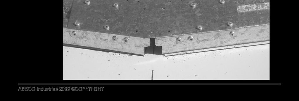
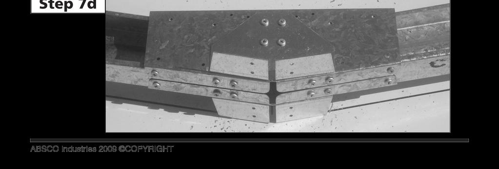
28 ABSCO CENTRE MID-FRAME ASSEMBLY ASSEMBLY SUPPORT PHOTOGRAPHS STEP A, B, C: Draw pattern on concrete, n accordance wth the dmensons detaled n the assembly nstructon. STEP A, B, C: Understand where components are to be postoned STEP 3A, B, C: Jon C06 to C704 STEP 4A, B, C: Jon C06 to C06 STEP 5A, B: STEP 6A, B: Secure rdge plate (RBP) Secure mult purpose brackets STEP 7A, B, C, D: Turn frame over, repeat steps 4,5 PAGE 8


29 PAGE 9


30 PAGE 30


31 PAGE 3


32 PAGE 3


33 PAGE 33


34 PAGE 34


35 PAGE 35
36 AUSTRALIA PRODUCT WARRANTY AGAINST DEFECTS Congratulatons on your purchase of an ABSCO SHED ABSCO SHEDS, ncludng garden sheds, garden beds, avares, storage unts, garages, awnngs and carports are made usng hgh qualty Australan made steel. We are pleased to advse we warrant that the steel coatng wll not rust, crack, flake peel or blster for 0 years from date of purchase, when nstalled wthn Australa. Ths warranty does not apply to surface deteroraton of panels caused by Swarf (Tny partcles of steel debrs left from cuttng, grndng or drllng operatons) that has not been removed after buldng constructon, or as a result of contact wth damp sol, chemcals, fertlsers or other corrosve substances. Ths warranty covers any Absco product used for normal domestc use and nstalled n accordance wth the nstallaton nstructons. The warranty does NOT cover Damage caused by storms, wnd, ran snow or poor foundatons. Ths warranty does NOT cover ABSCO products nstalled n severe coastal, ndustral or other hghly corrosve envronments. The warranty does not cover fasteners (screws, nuts, bolts, rvets, hasps or bolts). The warranty s lmted to replacement and delvery of components and does not nclude any labour or nstallaton costs. The benefts gven by the warranty are n addton to your other rghts and remedes under a law n relaton to the goods or servces to whch the warranty relates. The warranty apples to the excluson of all other representatons, guarantees or warrantes express or mpled, our goods come wth guarantees that cannot be excluded under the Australan consumer law and s not transferable. You are enttled to a replacement or refund for a major falure and for compensaton for any other foreseeable loss or damage. You are also enttled to have the goods repared or replaced f the goods fal to be of an acceptable qualty and the falure does not amount to a major falure. For further nformaton go to Please retan a proof of purchase (sales docket or nvoce) or regster your warranty wthn 30 days of purchase here: In the unlkely event a warranty clam s made, t must be supported by photographc evdence and detals of the defect, ncludng component part numbers, together wth proof of purchase documentaton (or on-lne regstraton of purchase) and forwarded to the address below. Upon recept of the warranty clam, the Customer Servce Manager wll contact you wthn three busness days to advse you of the assessment outcome of the clam, whch may nclude your expenses ncurred n makng the clam. THE CUSTOMER SERVICE MANAGER, ABSCO INDUSTRIES, PO BOX 9 ACACIA RIDGE QLD AUSTRALIA 40 PHONE: FAX: warranty@absco.com.au Issued 0 January 0 P a g e
37 ABSCO SHEDS - STORAGE GUIDELINES ABSCO SHEDS nclude garden sheds, garden beds, storage unts, avares, garages, awnngs and carports. ABSCO SHEDS are desgned to be weatherproof for normal weather condtons. In the event of extreme weather condtons such as heavy ran, combned wth hgh wnd gusts, the rdge cappng, sheetng jons, screw fxngs etc., may exhbt mnor deformatons whch may allow some water entry. These areas should be checked regularly to ensure that maxmum strength and protecton s mantaned. Other weather condtons such as extreme heat and extreme cold, most or dry ar can nfluence the effects of concrete floor mosture and/or condensaton on the undersde of the roof sheets. ABSCO SHEDS and storage unts are prmarly used for storage of garden equpment such as lawnmowers, wheelbarrows, garden tools etc. Storage tems that mght be adversely affected by any of the above condtons may requre addtonal protecton such as beng sealed or covered by plastc sheets and/or stacked above the concrete floor on tmber slats. Waterproof sealants may be used to offer further protecton where requred around jons and screw fxngs, as can rubber door seals and other products whch are avalable from most hardware outlets. Placement of waterproof sealants (slcone) between the base of the shed and concrete slab s not recommended, as ths process can have a reverse effect, preventng excess water from escapng, resultng wth water accumulatng and beng trapped nsde the shed. Absco accepts no responsblty for water entry, floor mosture, condensaton or the condton of the Contents nsde your Absco steel buldng arsng from any of the pre-mentoned weather condtons. P a g e
Absco Workshop Shed Model: 45302WK
 Absco Workshop Shed Model: FRONT: 4.48m SIDE: 3.0m HEIGHT: 2.m CONCRETE SLAB 300mm 4580mm CONCRETE WHEN LAYING YOUR CONCRETE SLAB, ENSURE THERE IS A REBATED EDGE 25mm DEEP AROUND THE PERIMETER 00mm REBATED
Premier Garden Shed Assembly Instructions Model: J30232GK
 Assembly Instructons Model: J303GK 360mm (7.7") CONCRETE SLAB 300mm (0.7'') FRONT: 3.0m (9.84") SIDE:.6m (7.4") HEIGHT:.m (6.88") WHEN LAYING YOUR CONCRETE SLAB, CHAMFER THE 50mm EDGES DOWNWARDS BY 0mm
Absco Premier Garden Shed Assembly Instructions Model: 30302GK
 Absco Premer Garden Shed Assembly Instructons FRONT: 3.0m SIDE: 3.0m HEIGHT:.m 300mm CONCRETE SLAB 300mm WHEN LAYING YOUR CONCRETE SLAB, CHAMFER THE 50mm EDGES DOWNWARDS BY 0mm. 50mm 0mm 50mm THIS WILL
Absco Space Saver Shed Assembly Instructions Model: J30082S
 Assembly Instructons FRONT BASE LENGTH: 9ft-0-7 64n SIDE BASE LENGTH: ft-6-45 64n FRONT WALL HEIGHT: 5ft-0-55 64n REAR WALL HEIGHT: 6ft-4-49 64n ft-0-4 64n CONCRETE SLAB 0ft--3 64n CONCRETE SLAB WHEN LAYING
Absco Industries Workshop Shed Model: 60303WK
 FRONT: 5.96m SIDE: 3.00m HEIGHT:.0m CONCRETE SLAB 300mm 6060mm WHEN LAYING YOUR CONCRETE SLAB, ENSURE THERE IS A REBATED EDGE 5mm DEEP AROUND THE PERIMETER THIS WILL HELP WATER EGRESS FROM THE BASE OF
Absco Regent Garden Shed Assembly Instructions Model: 30372RK
 Shed Assembly Instructons Model: 3037RK FRONT: 3.0m SIDE: 3.66m HEIGHT:.m 3760mm CONCRETE SLAB 300mm CONCRETE WHEN LAYING YOUR CONCRETE SLAB, ENSURE THERE IS A REBATED EDGE 5mm DEEP AROUND THE PERIMETER
Absco Space Saver Shed Assembly Instructions Model: 23081SK
 Assembly Instructons Model: 2308SK FRONT BASE LENGTH: 2.26m SIDE BASE LENGTH: 0.78m FRONT WALL HEIGHT:.80m REAR WALL HEIGHT:.95m CONCRETE SLAB 880mm 2360mm WHEN LAYING YOUR CONCRETE SLAB, CHAMFER THE 50mm
Absco EZISLIM Shed Model: 08151F
 FRONT: 0.78m SIDE: 1.52m HEIGHT: 1.80m CONCRETE SLAB 1620mm 880mm WHEN LAYING YOUR CONCRETE SLAB, CHAMFER THE 50mm EDGES DOWNWARDS BY 10mm. 50mm 10mm 50mm THIS WILL ENSURE THAT WATER RUN OFF IS KEPT CLEAR
Absco Aviary Assembly Instructions Model: A15301FK
 Absco Avary Assembly Instructons Model: A15301FK FRONT: 1.52m SIE : 2.96m HEIGHT: 1.8m 3060mm CONCRETE SLAB 1620mm WHEN LAYING YOUR CONCRETE SLAB, CHAMFER THE 50mm EGES OWNWARS BY 10mm. 50mm 10mm 50mm
Absco Pool Pump Cover Assembly Instructions Model: PPCK
 Cover Assembly Instructons Model: PPCK EXTERNAL BASE DIMENSIONS: 520mm x 520mm EXTERNAL REAR WALL HEIGHT: 490mm EXTERNAL FRONT WALL HEIGHT: 220mm RECOMMENDED CONCRETE SLAB SIZE: 620mm x 620mm x 00mm THICK
Organic Garden Co. Aviary Assembly Instructions Model: AOGC15081FKFD
 Assembly Instructons Model: AOGC508FKF FRONT:.52m SIE : 0.78m HEIGHT:.8m CONCRETE SLAB 880 620mm WHEN LAYING YOUR CONCRETE SLAB, CHAMFER THE 50mm EGES OWNWARS BY 0mm. 50mm 0mm 50mm THIS WILL ENSURE THAT
Absco Aviary Assembly Instructions Model: AOGC15151F
 Absco Avary Assembly Instructons FRONT:.52m SIE :.48m HEIGHT:.8m 580 CONCRETE SLAB 620mm WHEN LAYING YOUR CONCRETE SLAB, CHAMFER THE 50mm EGES OWNWARS BY 0mm. 50mm 0mm 50mm THIS WILL ENSURE THAT WATER
Absco Premier Garden Shed Assembly Instructions Model: 23231GK
 Absco Premier Garden Shed Assembly Instructions Model: 33GK FRONT:.6m SIDE:.6m HEIGHT:.00m 360mm CONCRETE SLAB 360mm WHEN LAYING YOUR CONCRETE SLAB, CHAMFER THE 50mm EDGES DOWNWARDS BY 0mm. 50mm 0mm 50mm
Absco Premier Garden Shed Assembly Instructions Model: J30302G
 Absco Premier Garden Shed Assembly Instructions FRONT: 9' 0 7 64" SIDE: 9' 0 7 64" HEIGHT: 6' 0 43 64" 0' 3 64" CONCRETE SLAB 0' 3 64" CONCRETE SLAB WHEN LAYING YOUR CONCRETE SLAB, ENSURE THERE IS A REBATED
Absco Premier Garden Shed Assembly Instructions Model: J30302G
 Absco Premier Garden Shed Assembly Instructions FRONT: 9ft-0-7 64in SIDE: 9ft-0-7 64in HEIGHT: 6ft-0-43 64in 0ft--3 64in CONCRETE SLAB 0ft--3 64in CONCRETE SLAB WHEN LAYING YOUR CONCRETE SLAB, ENSURE THERE
Absco Regent Shed Assembly Instructions Model: J30372R
 Absco Regent Shed Assembly Instructions FRONT: 9ft-0-7 64in SIDE: ft-3 3in HEIGHT: 6ft-0-43 64in ft-4-3in CONCRETE SLAB 0ft--3 64in CONCRETE SLAB WHEN LAYING YOUR CONCRETE SLAB, ENSURE THERE IS A REBATED
Absco Aviary Assembly Instructions Model: A23231G
 Absco Aviary Assembly Instructions Model: A23231G FRONT: 2.26m SIDE : 2.22m HEIGHT: 1.96m WHEN LAYING YOUR CONCRETE SLAB, CHAMFER THE 50mm EDGES DOWNWARDS BY 10mm. 50mm 10mm 50mm THIS WILL ENSURE THAT
Absco Space Saver Shed Assembly Instructions Model: J30082S
 Assembly Instructions FRONT BASE LENGTH: 9' 0 7 64" SIDE BASE LENGTH: ' 6 45 64" FRONT WALL HEIGHT: 5' 0 55 64" REAR WALL HEIGHT: 6' 4 49 64" CONCRETE SLAB ' 0 4 64" 0' 3 64" CONCRETE SLAB WHEN LAYING
Absco Highlander Shed Model: 3045HK
 FOR CONSTRUCTION IN NON-CYCLONIC AREAS WIND RATING: W33N (N2) FRONT: 3.0 m SIDE: 4.48m HEIGHT: 2.3 m CONCRETE SLAB 300mm 4580mm CONCRETE WHEN LAYING YOUR CONCRETE SLAB, ENSURE THERE IS A REBATED EDGE 25mm
INSTRUCTION MANUAL J23232GK
 We thank you for choosing an Australian Made Shed. For further assistance please visit our detailed instructional video library at Http://www.abscosheds.com.au/watch-videos At ABSCO Industries we are always
Absco Space Saver Shed Assembly Instructions Model: 15081S
 Assembly Instructions FRONT BASE LENGTH:.5m SIDE BASE LENGTH: 0.78m FRONT WALL HEIGHT:.8m REAR WALL HEIGHT:.95m CONCRETE SLAB 60mm 880mm WHEN LAYING YOUR CONCRETE SLAB, CHAMFER THE 50mm EDGES DOWNWARDS
C O N C E A L E D F I X I N G. PH:
 C O N C E A L E D I X I N G D I Y S l a t Systems PH: 1300 336 237 Alumnum Concealed xng Slat Systems Our Concealed xng Alumnum Slat range offers the latest n archtectural style combned wth a unque nstall
ASSEMBLY INSTRUCTIONS GG77. BASE SIZE: 2.190m x 2.020m
 ASSEMBLY INSTRUCTIONS GG77 BASE SIZE: 2.190m x 2.020m CONGRATULATIONS ON PURCHASING A DURATUF GUARDIAN SHED. BEFORE YOU BEGIN THE ASSEMBLY PLEASE NOTE SOME IMPORTANT POINTS: BEFORE YOU START: Read all
E N G L I S H GARDEN SHED. Assembly Instructions. Suitable for Models WITH VARYING DEPTHS
 GARDEN SHED Assembly Instructions Suitable for Models 6' Wide 8' Wide 0' Wide WITH VARYING DEPTHS GI0003 November 0 INSTALLATION ADVICE It's Not That Difficult! The construction of your shed isn't as complicated
ASSEMBLY INSTRUCTIONS SS2520. BASE SIZE: 2.520m x 2.020m
 ASSEMBLY INSTRUCTIONS SS50 BASE SIZE:.50m x.00m CONGRATULATIONS ON PURCHASING A SMART STORE SHED. BEFORE YOU BEGIN THE ASSEMBLY PLEASE NOTE SOME IMPORTANT POINTS: BEFORE YOU START: Read all instructions
English/French 06/04
 E000 PLEASE READ ASSEMBLY INSTRUCTIONS COMPLETELY BEFORE ASSEMBLING YOUR BUILDING CAUTION: Some parts have sharp edges. Care must be taken when handling the various pieces to avoid a mishap. For safety
INSTRUCTIONS FOR: GALVANIZED STEEL SHED MODEL No: GSS1515
 INSTRUCTIONS FOR: GALVANIZED STEEL SHED MODEL No: GSS1515 Thank you for purchasing a Sealey product. Manufactured to a high standard this product will, if used according to these instructions and properly
ASSEMBLY INSTRUCTIONS GL75. BASE SIZE: 2.190m x 1.520m
 ASSEMBLY INSTRUCTIONS GL75 BASE SIZE: 2.190m x 1.520m CONGRATULATIONS ON PURCHASING A DURATUF GUARDIAN SHED. BEFORE YOU BEGIN THE ASSEMBLY PLEASE NOTE SOME IMPORTANT POINTS: BEFORE YOU START: Read all
INSTRUCTIONS FOR: GALVANIZED STEEL SHED MODEL No: GSS1508
 INSTRUCTIONS FOR: GALVANIZED STEEL SHED MODEL No: GSS1508 Thank you for purchasing a Sealey product. Manufactured to a high standard this product will, if used according to these instructions and properly
GardenShed 2.3W x 2.3D x 2.4Hm
 GardenShed 2.3W x 2.3D x 2.4Hm 2.3m Gable Series Assembly instructions Congratulations on purchasing your new Pinnacle garden shed. Before assembling, we recommend you read the instructions thoroughly.
Model No. EP84-A, EP84AR-A, P84L
 E000 Model No. EP84-A, EP84AR-A, P84L PLEASE READ ASSEMBLY INSTRUCTIONS COMPLETELY BEFORE ASSEMBLING YOUR BUILDING CAUTION: Some parts have sharp edges. Care must be taken when handling the various pieces
ASSEMBLY INSTRUCTIONS
 Quality Built In ASSEMBLY INSTRUCTIONS MK3 BASE SIZE 3380mm x 1715mm ASSEMBLY INSTRUCTIONS Tools Required: Drill Drill Bit 3.5mm Drill Bit 6mm (for clear roof panel only) Hex Drive 5/16 Riveter Hammer
MODEL No: GSS3030G. Model No:...GSS3030G Overall Size (W x D X H*) x 3000 x 2100mm Roof Type:...Gable *Minimum Wall Height
 x 3000 x 2100mm Roof Type:...Gable *Minimum Wall Height") 1. SAFETY INSTRUCTIONS INSTRUCTIONS FOR: GALVANIZED STEEL SHED GREEN 3 x 3 x 2.1m MODEL No: GSS3030G Thank you for purchasing a Sealey product. Manufactured to a high standard, this product will, if used
1. SAFETY INSTRUCTIONS INSTRUCTIONS FOR: GALVANIZED STEEL SHED GREEN 3 x 3 x 2.1m MODEL No: GSS3030G Thank you for purchasing a Sealey product. Manufactured to a high standard, this product will, if used
INSTRUCTIONS FOR: GALVANIZED STEEL SHED 3 x 3 x 2.1mtr. MODEL No: GSS3030
 INSTRUCTIONS FOR: GALVANIZED STEEL SHED 3 x 3 x 2.1mtr MODEL No: GSS3030 Thank you for purchasing a Sealey product. Manufactured to a high standard this product will, if used according to these instructions
ASSEMBLY INSTRUCTIONS SS2010. BASE SIZE: 2.020m x 1.020m
 ASSEMBLY INSTRUCTIONS SS010 BASE SIZE:.00m x 1.00m CONGRATULATIONS ON PURCHASING A SMART STORE SHED. BEFORE YOU BEGIN THE ASSEMBLY PLEASE NOTE SOME IMPORTANT POINTS: BEFORE YOU START: Read all instructions
SteelChief Installation Instructions for pre-assembled panel form sheds GABLE ROOF
 SteelChief Installation Instructions for pre-assembled panel form sheds GABLE ROOF Please read fully before commencing work...any queries will be promptly answered, contact theboss@steelchief.com.aui MPORTANT
GALVANIZED SHED GREEN 2.3 X 2.3 X 1.9m
 INSTRUCTIONS FOR: GALVANIZED SHED GREEN 2.3 X 2.3 X 1.9m MODEL NO: GSS2323G Thank you for purchasing a Sealey product. Manufactured to a high standard, this product will, if used according to these instructions,
ASSEMBLY INSTRUCTIONS
 Quality Built In ASSEMBLY INSTRUCTIONS MK4B BASE SIZE 4210mm x 3380mm ASSEMBLY INSTRUCTIONS Tools Required: Drill Drill Bit 3.5mm Drill Bit 6mm (for clear roof panel only) Hex Drive 5/16 Riveter Hammer
AWNING / PATIO COVER INSTALLATION INSTRUCTIONS
 AWNING / PATIO COVER INSTALLATION INSTRUCTIONS Before You Begin Read the installation instructions thoroughly before beginning the installation procedure. Perspective In the Awning Instructions, Back means
2E - 3E High Wind Kit Manual
 Yag Dpole Vertcal (Patent# 6,677,914 E - 3E Hgh Wnd Kt Manual Antarctca at 7 mph SteppIR Antennas 11-116th Ave NE, Sute -, Bellevue, WA 984 Tel: 4-43-191 Fax: 4-46-441 Tech Support: 4-891-6134 www.steppr.com
GM3015 ASSEMBLY. 1 cardboard package 1 channel pack. Tools supplied: 1 Riveter 3.3mm double ended drillbit. Tools required: Tape measure Ladder
 M3015 SLOPIN ROO SHED 3030mm wide x 1530mm deep x 1980-1830mm high 25 YER WRRNTY SSEMBLY INSTRUCTION DVD WITH LL SHEDS SSEMBLY INSTRUCTIONS You should have two packages: 1 cardboard package 1 channel pack
Installation Manual for Metal Emperor Lockers
 P a g e 1 Table of Contents Page General Notes and Tools Required 2-3 Assemble Shelves with Coat Hooks/Coat Rods 4 Fastening Chart 5 Knock Down Locker Assembly (Banks of Three) 6-12 Appendix A: Dress End
GROWING BETTER THROUGH DESIGN. 6ft Lean-To LEAN-TO. Assembly Instructions 04/02
 GROWING BETTER THROUGH DESIGN 6ft Lean-To LEAN-TO Assembly Instructions 04/02 6ft Lean-To Greenhouse Base Plan Introduction/Tools/Contents / / Contents This is a copy of our Lean-To greenhouse base plan.
PINEHAVEN SHEDS Assembly Instructions FOR LEAN-TO SHEDS
 PINEHAVEN SHEDS Assembly Instructions FOR LEAN-TO SHEDS GARDEN PRODUCTS www.pinehavensheds.co.nz 5/16 hex drive bit, By asking about our products at your nearest DIY or gardening store www.pinehavensheds.co.nz
S H E D A S S E M B L Y I N S T R U C T I O N S
 T I T A N R A N G E S H E D A S S E M B L Y I N S T R U C T I O N S 6 X 4ft = 190 x 150 cm 6 X 6ft = 190 x 190 cm 6 X 8ft = 190 x 255 cm COMPONENT LIST Component illustrations are given as a visual guide
FREE RANGE TM 59 X59 X78 HEN HOUSE TM
 FREE RANGE TM 59 X59 X78 HEN HOUSE TM Assembly Instructions Congratulations on purchasing your new FREE RANGE TM Chicken Coop. Before starting the assembly, we recommend that you read the instructions
8x12 SpaceMaker Garden Shed Assembly Manual
 8x12 SpaceMaker Garden Shed Assembly Manual Version #6 Revised June / 2007 Thank you for purchasing a 8x12 SpaceMaker Garden Shed. Please take the time to identify all the parts prior to assembly. Safety
DUTCH GABLE CARPORT RECOMMENDED INSTRUCTION MANUAL
 DUTCH GABLE CARPORT RECOMMENDED INSTRUCTION MANUAL Table of Contents Introduction 2 Components 3 Step 1a Marking out the Perimeter of the Carport with Footing only 4 Step 2a Footing Set-Out for Concrete
GABLE ROOF CARPORT RECOMMENDED INSTRUCTION MANUAL
 GABLE ROOF CARPORT RECOMMENDED INSTRUCTION MANUAL Table of Contents Introduction 2 Components 3 Step 1a Marking out the Perimeter of the Carport with Footing only 3 Step 2a Footing Set-Out for Concrete
ASSEMBLY INSTRUCTIONS
 Quality Built In ASSEMBLY INSTRUCTIONS MK4A BASE SIZE 4.210mm x 2545mm ASSEMBLY INSTRUCTIONS Tools Required: Drill Drill Bit 3.5mm Drill Bit 6mm (for clear roof panel only) Riveter Hammer Nail Punch Tape
GM1511 ASSEMBLY. 1 cardboard package. Tools supplied: 1 Riveter 3.3mm double ended drillbit. Tools required: Tape measure Ladder
 GM1511 SLOPING ROO SHD 1530mm wide x 1080mm deep x 1830-1770mm high 25 YAR WARRANTY ASSMLY INSTRUCTION DVD WITH ALL SHDS ASSMLY INSTRUCTIONS You should have one package: 1 cardboard package Tools supplied:
S H E D A S S E M B L Y I N S T R U C T I O N S
 T I T A N R A N G E S H E D A S S E M B L Y I N S T R U C T I O N S 8 X 10 ft Approx = 2550 x 3140 cm COMPONENT LIST Component illustrations are given as a visual guide only and are not in proportion PART
Potting Store Assembly Instructions
 Before assembly We recommend that time is taken to read the instructions before starting assembly, then follow the easy step by step guide. The instruction sheet is only a guide to the assembly. Certain
Safety Glasses Safety Gloves Ladders Measuring Tape Spirit Level String Line. Tin-Snips Rivet Gun Caulking Gun Silicone Socket Set
 BEFORE YOU START Carefully read these instructions and refer to them constantly during each stage of construction. If you do not have all the necessary tools or information, contact Stratco for advice.
Dura-Lock Roof System
 DLR-14 Dura-Lock Roof System Assembly and Installation Instructions Read the instructions before starting the job. They explain the steps required to produce a finished product that will meet factory specifications.
INSTRUCTIONS FOR ASSEMBLY 2355mm x 3125mm Workshop
 Manufacturer of Christie Glasshouses and Sheds INSTRUCTIONS FOR ASSEMBLY 2355mm x 3125mm Workshop 1 Thomas Burns Street, Dunedin Phone (03) 477 7909 www.allans.co.nz Congratulations on your purchase of
Corner Potting Store Assembly Instructions
 Corner Potting Store Assembly Instructions English SS225E Before assembly We recommend that time is taken to read the instructions before starting assembly, then follow the easy step by step guide. The
TrendWall Floor-To-Ceiling Panels Installation Instruction
 TrendWall Floor-To-Ceiling Panels Installation Instruction TrendWall Components Covered by this Instruction: Crown (and accessories) Floor Plate Solid Panel Filler Panel Wall Channel Door Section Pilaster
Track Rack. * Track Racks are not lockable
 The Track Rack s unique staggered, sliding hook design creates the greatest parking efficiency while still providing easy access to any particular bike. When adding or removing a bike to the rack, simply
It is important that you contact your local government authority to determine if building approval is required.
 HANDI-MATE SHED HANDI-MATE LOCKER INSTALLATION GUIDE INSTALL GUIDE BEFORE YOU START PRIOR TO INSTALLATION It is important that you contact your local government authority to determine if building approval
ASSEMBLY INSTRUCTIONS FOR STORETTE STA42
 ASSEMBLY INSTRUCTIONS FOR STORETTE STA42 A01 CAUTION: Some parts have sharp edges. Care must be taken when handling the various pieces to avoid a mishap. For safety sake, please read the safety information
WORKSHOP. 1015HDDA, 1019HDDA m WALL HEIGHT 1015HDDA2, 1019HDDA2-2m WALL HEIGHT OPTIONAL SINGLE HINGED DOOR INSTRUCTION MANUAL INCLUDED
 DOUBLE HINGED DOOR 15 19 WORKSHOP 1015HDDA, 1019HDDA - 1.78m WALL HEIGHT 1015HDDA2, 1019HDDA2-2m WALL HEIGHT OPTIONAL SINGLE HINGED DOOR INSTRUCTION MANUAL INCLUDED (Available in Australia only) TRECO
DUTCH GABLE FREESTANDING CARPORT
 DUTCH GABLE FREESTANDING CARPORT STRATCO OUTBACK ASSEMBLY INSTRUCTIONS. Your complete guide to building a FREESTANDING Outback DUTCH GABLE CARPORT BEFORE YOU START Carefully read these instructions. If
INSTRUCTIONS FOR ASSEMBLY 2355mm x 4665mm Workshop
 Manufacturer of Christie Glasshouses and Sheds INSTRUCTIONS FOR ASSEMBLY 2355mm x 4665mm Workshop 1 Thomas Burns Street, Dunedin Phone (03) 477 7909 www.allans.co.nz Congratulations on your purchase of
GALVANIZED SHED 2.3 X 2.3 X 1.9M
 INSTRUCTIONS FOR GALVANIZED SHED 2.3 X 2.3 X 1.9M MODEL NO: GSS2323 & GSS2323G Thank you for purchasing a Sealey product. Manufactured to a high standard, this product will, if used according to these
WORKSHOP 1015A, 1019A m WALL HEIGHT 1015A2, 1019A2-2m WALL HEIGHT
 DOUBLE SLIDING DOOR 15 19 WORKSHOP 1015A, 1019A - 1.78m WALL HEIGHT 1015A2, 1019A2-2m WALL HEIGHT OPTIONAL SINGLE HINGED DOOR INSTRUCTION MANUAL INCLUDED (Available in Australia only) TRECO SHEDS ARE MANUFACTURED
Assembly instructions. 6x4. Model GH1354A. 6x6. Model GH1357A. 6x8. Model GH1360A. 6x10. Walk-in Greenhouse. Model GH1363A
 ssembly instructions x Model GH x Model GH7 x8 Model GH0 x0 Model GH Walk-in Greenhouse Statement ear Customer! May we congratulate you on your new Greenhouse. We feel sure that by following the detailed
 SUPREME WALL GARDEN ASSEMBLY INSTRUCTIONS 24/08/16 www.hallsgreenhouses.com Please refer to website for the most up to date instructions. SAFETY WARNING 1. Always wear protective glasses, shoes, gloves
INSTALLATION GUIDE. Outback. Flat Attached BEFORE YOU START ADDITIONAL MATERIALS TOOLS REQUIRED. VERAnDAHS PATIOS CARPORTS
 INSTALLATION GUIDE Outback VERAnDAHS PATIOS CARPORTS Flat Attached BEFORE YOU START It is important to check your Local Government Authority requirements before the installation of your new Stratco Outback
IDAHO ASSEMBLY INSTRUCTIONS. BASE SIZE: 1.800m x 1.200m
 IDAHO ASSEMBLY INSTRUCTIONS BASE SIZE: 1.800m x 1.200m IDAHO Tools Required: Battery Drill Riveter Hammer Tape Measure Ladder Skillsaw Level Square Drive Bit No.2 3/8 Hex Drive Bit 8mm Hex Drive Bit Drill
NEVADA ASSEMBLY INSTRUCTIONS
 NEVADA ASSEMBLY INSTRUCTIONS BASE SIZE: 2.700m x 1.500m NEVADA Tools Required: Battery Drill Riveter Hammer Tape Measure Ladder Skillsaw Level Screwdriver - Flat 3/8 Hex Drive bit 8mm Hex Drive bit Drill
OUTBACK FLAT ATTACHED VERANDAH PATIO CARPORT - INSTALLATION GUIDE BEFORE YOU START TOOLS REQUIRED ADDITIONAL MATERIALS
 BEFORE YOU START It is important to check your Local Government Authority requirements before the installation of your new Stratco Outback Flat Verandah. It is the builder s responsibility to ensure any
Gardman Lean-to Greenhouse Assembly Instructions
 Page 1 Gardman Lean-to Greenhouse Assembly Instructions Our Help Line provides support and advice to customers of Summer Garden Buildings after ordering. For advice before you buy you can phone us free
Ensure there is reasonable access for materials and working space, ensure the shed site is level and consider the disposal of run-off water.
 INSTALLATION GUIDE TM Flat Roof Homesheds THE POTTER BEFORE YOU START It is important to check your Local Government Authority requirements before the installation of your new Stratco Potter Flat Roof
ASSEMBLY INSTRUCTIONS FOR "GA" MODULAR BUILDINGS ALL MODELS
 ASSEMBLY INSTRUCTIONS FOR "GA" MODULAR BUILDINGS ALL MODELS W01 CAUTION: Some parts have sharp edges. Care must be taken when handling the various pieces to avoid a mishap. For safety sake, please read
ALL SEASON PATIO COVER
 ALL SEASON PATIO COVER 61 Where the All Season Patio Cover is to be attached to the home, create a level line showing where the top of the mounting rail is to be located. Install each section with the
PRO- CRIMPER* III Hand Crimping
 PRO- CRIMPER* III Hand Crmpng Instructon Sheet Tool 58448-2 408-9357 Wth De 58448-3 10 Mar 11 PROPER USE GUIDELINES Cumulatve Trauma Dsorders can result from the prolonged use of manually powered hand
GALVANIZED STEEL SHED 1510 x 1510 x 1900mm
 INSTRUCTIONS FOR: GALVANIZED STEEL SHED 1510 x 1510 x 1900mm MODEL No s: GSS1515.V2, GSS1515G.V2 Thank you for purchasing a Sealey product. Manufactured to a high standard, this product will, if used according
PRO- CRIMPER* III Hand Crimping
 PRO- CRIMPER* III Hand Crmpng Instructon Sheet Tool Assembly 91338-1 408-8377 wth De Assembly 91338-2 22 JUL 09 PROPER USE GUIDELINES Cumulatve Trauma Dsorders can result from the prolonged use of manually
GALVANIZED STEEL SHED 1.5 x 0.8 x 1.5M
 INSTRUCTIONS FOR GALVANIZED STEEL SHED 1.5 x 0.8 x 1.5M MODEL NO: GSS150815G Thank you for purchasing a Sealey product. Manufactured to a high standard, this product will, if used according to these instructions,
6x6 Maximizer Storage Shed Assembly Manual Version #9 Feb 26th, 2015
 6x6 Maximizer Storage Shed Assembly Manual Version #9 Feb 26th, 2015 Thank you for purchasing a 6x6 Maximizer Storage Shed. Please take the time to identify all the parts prior to assembly. Please Note-
Taurean Sectional Garage Door INSTALLATION INSTRUCTIONS
 BEFORE YOU BEGIN MAKE SURE THESE INSTRUCTIONS ARE READ AND UNDERSTOOD COMPLETELY. THESE INSTRUCTIONS ARE INTENDED FOR PROFESSIONAL GARAGE DOOR INSTALLERS. ALL REFERENCES ARE TAKEN FROM THE INSIDE LOOKING
Best Barns USA Assembly Book Revised October 24, 2017
 Best Barns USA Assembly Book Revised October 24, 2017 Garage Door by Owner the Tahoe 12'x 16' Manufactured by Reynolds Building Systems, Inc. 205 Arlington Drive Greenville, PA 16125 This manual is copyrighted.
10x10 Trellis Pergola
 0x0 Trellis Pergola ASSEMBLY GUIDE Ver.0-7 Table of Contents PAGE Introduction & Overview...................................................... Pergola Materials Overview..............................................................
INSTALLATION GUIDE. Flat Roof Homesheds TM. Onto Concrete BEFORE YOU START TOOLS REQUIRED
 INSTALLATION GUIDE Flat Roof Homesheds TM Onto Concrete BEFORE YOU START It is important to check your Local Government Authority requirements before the installation of your new Stratco Flat Roof Homeshed.
HANDI-MATE SHED BEFORE YOU START INSTALL GUIDE HINGED DOOR HANDI-MATE INSTALLATION GUIDE PRIOR TO INSTALLATION
 HANDI-MATE SHED HINGED DOOR HANDI-MATE INSTALLATION GUIDE INSTALL GUIDE BEFORE YOU START PRIOR TO INSTALLATION It is important that you contact your local government authority to determine if building
TRADITIONAL GABLE ATTACHED PATIO AND CARPORT. Your complete guide to building an ATTACHED Outback TRADITIONAL GABLE PATIO or CARPORT
 TRADITIONAL GABLE ATTACHED PATIO AND CARPORT STRATCO OUTBACK ASSEMBLY INSTRUCTIONS. Your complete guide to building an ATTACHED Outback TRADITIONAL GABLE PATIO or CARPORT BEFORE YOU START Carefully read
STRATCO GABLE HOMESHED STRATCO GABLE HOMESHEDS STUBBIE INSTALLATION GUIDE
 STRATCO GABLE HOMESHED STRATCO GABLE HOMESHEDS STUBBIE INSTALLATION GUIDE INSTALL GUIDE BEFORE YOU START COUNCIL APPROVAL It is important that you have local council approval before building your Stratco
Best Barns USA. Assembly Book. 12'x 16' the Millcreek. Revised September 19, 2017
 Assembly Book Best Barns USA Revised September 19, 2017 the Millcreek 12'x 16' Manufactured by Reynolds Building Systems, Inc 205 Arlington Drive Greenville, PA 16125 This manual is copyrighted Under the
onlinecomponents.com
 PRO- CRIMPER* III Hand Crmpng Instructon Sheet Tool Assembly 58535-1 wth 408-4021 De Assembly 58535-2 29 JUL 09 PROPER USE GUIDELINES Cumulatve Trauma Dsorders can result from the prolonged use of manually
Extra Wide Designer Lockers Series Installation Instructions
 Extra Wide Designer Lockers 20000 Series Thank you for selecting the 20000 Series Extra Wide Designer Lockers. We are confident that the quality and construction of the lockers will prove to be a good
2.4 x 1.8 (8 x 6 ) Premier Shiplap Modular Shed Assembly Instructions
 Premier Shiplap Modular Shed Assembly Instructions") 2.4 x 1.8 (8 x 6 ) Premier Shiplap Modular Shed Assembly Instructions English SS197C Before assembly We recommend that time is taken to read the instructions before starting assembly, then follow the easy
2.4 x 1.8 (8 x 6 ) Premier Shiplap Modular Shed Assembly Instructions English SS197C Before assembly We recommend that time is taken to read the instructions before starting assembly, then follow the easy
Greenhouse Assembly Instructions
 Greenhouse Assembly Instructions Our Help Line provides support and advice to customers of Summer Garden Buildings after ordering. For advice before you buy you can phone us free 7 days a week on 0800
PRO- CRIMPER* III Hand
 PRO- CRIMPER* III Hand Instructon Sheet Crmpng Tool Assembly 58529-1 408-9999 wth De Assembly 58529-2 11 AUG 14 PROPER USE GUIDELINES Cumulatve Trauma Dsorders can result from the prolonged use of manually
Best Barns USA Assembly Book
 Best Barns USA Assembly Book Revised February 4, 2016 the Millcreek-R 12'x 16' Manufactured by Reynolds Building Systems, Inc. 205 Arlington Drive Greenville, PA 16125 724-646-3775 This manual is copyrighted.
RH-412 STEEL DOORS INSTALLATION INSTRUCTIONS
 RH-412 STEEL DOORS INSTALLATION INSTRUCTIONS By following the steps outlined below, the assembly, installation and adjustment of the steel doors, will be a simple process. Let s start with the Driver Side.
ALUMA-VENT AWNING REGULAR END STYLE INSTALLATION INSTRUCTIONS
 ALUMA-VENT AWNING REGULAR END STYLE INSTALLATION INSTRUCTIONS Contact us at: 1-888-442-2928 or www.americana.com Options in your kit: A. Splice Pg 16 B. Column Pg 17 C. C-Channel Brace Pg 19 D. Runner
Best Barns USA Assembly Book
 Best Barns USA Assembly Book Revised September 19, 2017 Garage Door by Owner the Tahoe 12'x 20' Manufactured by Reynolds Building Systems, Inc. 205 Arlington Drive Greenville, PA 16125 This manual is copyrighted.
W6 series greenhouse
 W series greenhouse ssembly instructions Model W0 Model W07 Model W0 Model W Model W Walk-in Greenhouse Statement Dear Customer! May we congratulate you on your new Greenhouse. We feel sure that by following
10x10 Trellis Pergola
 0x0 Trellis Pergola ASSEMBLY GUIDE Ver.-007 Table of Contents PAGE 0x0 Trellis Pergola Introduction & Overview...................................................... Pergola Materials Overview..............................................................