Fiber Optic Communications. Photonics and Fiber Optics Systems
|
|
|
- Sharleen Wright
- 5 years ago
- Views:
Transcription

1 Fiber Optic Communications Photonics and Fiber Optics Systems

2 Optical Fibers. Fibers of glass Usually 120 micrometers in diameter Used to carry signals in the form of light over distances up to 50 km. Photonics and Fiber Optics Systems No repeaters needed.

3 Optical Fibers. Core thin glass center of the fiber where light travels. Cladding outer optical material surrounding Photonics the and core Fiber Optics Systems Buffer Coating plastic coating that protects the fiber.

4 Figure of Merit for Transmission Bandwidth-distance product Throughput Bit error rate Photonics and Fiber Optics Systems

5 Advantages Thinner Less Expensive Higher Carrying Capacity Less Signal Photonics Degradation and Fiber Optics Systems Light Signals Non-Flammable Light Weight
6 Evolution of Fiber 1880 Alexander Graham Bell 1930 Patents on tubing 1950 Patent for two-layer glass wave-guide 1960 Laser first used as light source Photonics and Fiber Optics Systems 1965 High loss of light discovered 1970s Refining of manufacturing process 1980s becomes backbone of long distance telephone networks in North America.
7 Areas of Application Telecommunications Local Area Networks Cable TV Photonics and Fiber Optics Systems CCTV Optical Fiber Sensors
8 Type of Fibers Single-mode fibers used to transmit one signal per fiber (used in telephone and cable TV). They have small cores(9 microns in diameter) and transmit infra-red light from laser. Photonics and Fiber Optics Systems Multi-mode fibers used to transmit many signals per fiber (used in computer networks). They have larger cores(62.5 microns in diameter) and transmit infra-red light from LED.
9 Working Principle Light?? Total Internal Reflection. Fibre Optics Relay Systems has -Transmitter Photonics and Fiber Optics Systems -Optical Fibre -Optical Regenerator -Optical Receiver

10 Total Internal Reflection Photonics and Fiber Optics Systems
11 Total reflection medium 1 evanescent field Photonics and Fiber Optics Systems medium 2 q i >qc critical angle q=qc q i <qc total reflection and evanescent wave


12 Attenuation and dispersion Attenuation: reduction of light amplitude Dispersion: deterioration of waveform Photonics and Fiber Optics Systems
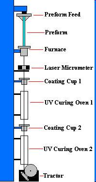
13 How are Optical Fibre s made?? Three Steps are Involved -Making a Preform Glass Cylinder -Drawing the Fibre s from the preform Photonics and Fiber Optics Systems -Testing the Fibre


14 Photonics and Fiber Optics Systems
15 Generic Optical Comm. System Input Optical Transmitter Comm. Channel Optical Receiver Output Format Bandwidth Protocol Photonics and Fiber Optics Systems Modulation Characteristics Power Wavelength Loss Dispersion 4-Wave Mixing Noise Crosstalks Distortion Amplification Bandwidth Responsivity Sensitivity Noise Wavelength

16 Wavelength Division Multiplexing Photonics and Fiber Optics Systems
17 Fiber-to-the-Home Definition a telecommunications architecture in which a communications path is provided over optical fiber cables from the Photonics and Fiber Optics Systems operator s switching equipment to the boundary of the home living space

18 Fiber-to-the-Home Network Evolution From All-Copper to All-Fiber CO CO Photonics and Fiber Optics // Systems Old networks, optimized for voice 24 kbps Mbps CO/HE // Optical networks, optimized for voice, video and data 19 Mbps - 1 Gbps +
 // 1550 nm")
19 Fiber-to-the-Home Wavelength Allocation OLT // // 1490 nm (data) // // Photonics and Fiber Optics Systems // // ONT 1310 nm (voice) // 1550 nm (video) //
20 Fiber-to-the-Home Service Delivery Comparison Downstream Data Rate, Mbps Upstream Data Rate, MBPS Reach (K feet) Satellite Photonics and Fiber Optics Systems Cable Modem (HFC) ADSL (voice, data) VDSL (voice, data, video) Wi-Fi 11 1 >1 FTTH PON 622 > FTTH - PtP
 Data")

")
21 Fiber-to-the-Home Voice (Telephone) Data (Internet) Photonics and Fiber Optics Systems Video (SDTV, HDTV, Video-on-Demand) Triple Play

22 Fiber-to-the-Home Fiber to the Condominium Unit - Home Automation Features of Home Automation Video Surveillance Lighting (including scene lighting) Heating and Air Conditioning Photonics and Fiber Home Optics Audio Systems Home Video Pool Equipment and Water Features Control your home from anywhere: Graphical touch screens Any Phone Any Computer

23 Fiber-to-the-Home FTTH Penetration as of Mid 2008 Photonics and Fiber Optics Systems
24 References [1] H. Kolimbiris, Fiber Optics Communications, Int. Edition, Pearson Education, 2004 [2] J. G. Proakis, Digital Communications, Fourth Edition, McGraw Hill, 2001 [3] J. C. Palais, Fiber Optic Communications, Fifth Edition, Pearson Education, Photonics 2005 and Fiber Optics [4] G. P. Agrawal, Systems Fiber-optic Communication Systems, Third Edition, John Wiley & Son, 2002 [5] [6] Light connects us
25 06/01/09 Optical sources and amplifiers
26 Laser diodes Laser diodes are very similar to the structure of light emitting diodes. The main difference is the requirement of optical feedback to be able to establish laser oscillation. This is done by cleaving and polishing the end faces of the junction diodes to act as mirrors. 06/01/09
27 Laser diodes Qualitatively, the functionality of the laser diode can be described as follows : Forward current injects holes and electrons into the junction. Photons in the junction stimulate electron-hole recombination, with emission of added photons. This process yields gain. If the gain exceeds the losses, oscillation occurs. Therefore the gain must exceed a threshold value. To obtain this threshold, the current must be greater than a certain value called the threshold current. 06/01/09
28 Laser diodes What are the sources of losses? The losses happens because of absorption and in the case of the laser diode the spontaneous emission also contribute to losses indirectly WHY not like LED case? In the case of the LED the spontaneous emission is the only source of light and it happens as the forward bias increases with a very low threshold voltage. In this case there resonance due to cleaving of the LD walls which would attenuate most of the spontaneous emission since it is random and cannot be fixed at a certain wavelength and so the only outcome is the reduction of population inversion and lowering the efficiency resonance and stimulated emission 06/01/09
29 Homojunction vs. heterojunctions The LED and the LD mentioned before were both described as homojunctions. A homojunction is a PN junction formed with a single semiconductor material. Homojunctions do not confine the light emitted very well as the junction is usually relatively large which causes light emission to be over a large angle and surface area which coupled to fiber very inefficiently. A heterojunction is a junction formed by dissimilar semiconductors. 06/01/09
30 Homojunction vs. heterojunctions Most LD are made of heterojunctions as they are much more efficient in light emission and in confinement of emission suitable for efficient coupling. This different materials will have different band gaps which can be designed to limit the distance over which the minority carrier may diffuse and also reduce the amount of absorption of generated photon. The figure below illustrate the band diagram of a double hetero-junction before connection P P N Eg1 Eg2 Eg3 06/01/09
31 Functionality of heterojunctions P P N Eg1 Eg2 E f Eg3 When the structure is connected the Fermi level must remain constant for thermal equilibrium and because of the middle p-layer is smaller in band gap than the other two layers when the structure is forward biased electrons would flow to the middle p region but would be confined in that region since there is a potential barrier due to the difference in band gap limiting them from diffusing further in the adjacent p region. 06/01/09
32 Functionality of heterojunctions By keeping the middle layer extremely small (~0.1µm) the emitted photon can be confined to a very small area. Another advantage is that photons generated in other layers which move to the middle layer cannot be absorbed since it will have a different energy value than the band gap of the middle layer. 06/01/09
33 Laser diode operating characteristics 5 I TH = threshold current P(optical) (mw) Actual Ideal Example: I TH = 75 ma Diode Voltages Volts 0 I TH 100 I (ma) Below the threshold current there is a small increase in optic power with the drive current. This is non-coherent sponteneous emission in 耠汭 e recombination layer. (Why so small?) 06/01/09
34 Digital modulation Digital Modulation Optical Power Optical Power I TH I dc t 1 i s 0 1 t Input Current or Signal 06/01/09
35 Analogue modulation Analog Modulation Optical Power P sp Optical Power I dc P dc I For the analogue case, the dc bias must TH be beyond the threshold point to ensure that operation will be along the linear portion of the power-current characteristic curve. t Input Current (Signal) 06/01/09
36 Temperature dependence 5 P (mw) 30 C 80 C i (ma) 06/01/09
37 Temperature dependence As the temperature increases the diode gain decreases and so more current is required to overcome the losses and for oscillation to begin. The consequence is that the threshold current increases with the increase of temperature as shown in the previous figure. The reason for this happening can be explained as follows: increasing the temperature increase the energy of more electrons and holes to be free outside the active layer (in the n and p layers). More recombination happens outside the active layer with free carriers that would have reached the active layer but recombine instead. This reduces the number of charges reaching the active layer and consequently reducing stimulated emission and diode gain. In optical communication this might have drastic consequences as at constant current, if the temperature of the diode rises this will reduces the output power. Large reduction in power might increase detection error at the receiver and so reducing the overall performance of the communication system. 06/01/09
38 Laser wavelength dependence on temperature The wavelength is dependent on the temperature as consequence of the dependence of the refractive index of the material on temperature. Recall the cavity resonant frequency is given by : mc T 1 = 27 C f = 2Ln Cavity Resonance Output T 2 = 30 C Cavity Resonance Output 06/01/09
39 Laser spectral widths Laser diode typically posses line width between 1-5nm which is much smaller than that of an LED. Unlike the HeNe gas laser, in this case the emitting transition is happening in a semiconductor which occurs between energy bands not distinct lines as the case in gases. Therefore the line width is larger than that of a HeNe laser (which is typically of the order of 10-3 nm). 06/01/09
40 Laser spectral widths The cavity also affects the output spectrum. The cavity dimension can cause many longitudinal modes to co-exist. Recall : the cavity resonant wavelength spacing is given by : 2 = λ o λ c c f c Where : c f c = 2Ln Thus λo c λ c= = c 2Ln 2 λ 2 o 2Ln 06/01/09
41 Laser spectral widths example Assume: λ 0 = 0.82 µm, L = 300 µm, n = 3.6 λ = 2 nm (laser linewidth) Then (0.82) 2(300) c = = m = 0.311nm l m The number of longitudinal modes is approximately N m = l c N m = 2nm 0.311nm = /01/09
42 Plot of the laser modes For the laser diode we have: Gain nm λ c λ (nm) Cavity Resonances λ (nm) Output Spectrum λ c λ (nm) 06/01/09
43 Distributed feedback laser diode Distributed feedback (DFB) lasers is a type of laser which produces very narrow linewidth (single longitudinal mode laser). The figure below shows the structure of a DFB laser from inside. Metallization Λ Different Materials p Grating Cleaved Face n Active Layer The grating (etched just above the active layer) acts as a wavelength selective filter, permitting only one of the cavity s modes to propagate. 06/01/09
44 Distributed feedback laser diode Laser Gain λ Cavity Resonances λ Grating Resonances λ Laser Output λ 06/01/09 λ 0
45 Distributed feedback laser diode The grating resonances, according to Bragg s law, are those wavelengths for which the grating period Λ (illustrated on a preceding slide) is an integral number of half-wavelengths. That is: m λ Λ = 2 λ is the wavelength in the diode, m is an integer λ0 is the free-space wavelength λ = The grating period then satisfies : l æö 0 Λ = mç è2 n ø λ 0 n l 0 2nΛ = m 06/01/09
46 Distributed feedback laser diode Example: Consider an InGaAsP DFB LD λ 0 = 1.55 µm, n = 3.5, let m = 1 (first order) Determine the grating period. Λ = mλ 2n (3.5) 0 = = 0.22 µ m Let m = 2 (second order) Λ = mλ 2n 2(1.55) 2(3.5) 0 = = 0.44 µ m 06/01/09
47 Tunable laser diodes There is a need in fiber systems for sources which can be tuned to precise wavelengths. The most common examples are the WDM systems, where a number of closely spaced wavelengths are needed to provide multiple carriers on the same fiber. One possibility is to tune a DFB LD by changing its temperature or its drive current (which changes its temperature). Tuning is on the order of 10-2 nm/ma. 06/01/09
48 Tunable laser diodes This can be useful but if we want to use it as a WDM source this will not be practical as typical WDM systems will need tunability in the range of 10nm or more. For this reason another variation of the DFB LD can be used which called distributed bragg reflector laser diode. 06/01/09
49 DBR laser diode In a DBR LD there are three regions : the gain, the Bragg and the phase. Each region is supplied with a separate currents as shown in the diagram. The gain current (I G ) determines the amplification in the active region and so the level of the output power. 06/01/09
50 DBR laser diode The phase current (I P ) act as a control of the feedback from the bragg reflection by changing the phase of the wave reflected from the Bragg region through heating the phase layer which changes its refractive index. The current (I B ) control the Bragg wavelength by changing the temperature in the Bragg region which again changes the refractive index. I G I P I B p CLEAVED FACET n GAIN PHASE BRAGG 06/01/09
51 DBR laser diode The operating wavelength, can be given by : λ 0 = 2n eff Λ assuming the first order resonance (m=1), and λ 0 is the free-space emitted wavelength, and n eff is the effective refractive index. The tuning range ( λ) is proportional to the effective refractive index variation ( n eff ). λ n = λ n If the center wavelength is 1500 nm, the tuning range would be 15 nm. eff eff 06/01/09
52 Optical amplifiers Fiber optic systems are mainly limited by either bandwidth or attenuation. If we are transferring a digital signal via a fiber optic link a regenerator can be inserted in the middle if the link is too long and the signal is severely attenuated. The regenerator detects the optical signal, converting it to the electrical form, detects the ones and zeros and removes the pulse spreading and distortions then reconverts the signal to an optical form to be resent via the optical link. 06/01/09
53 Optical amplifiers In an analogue signal the situation is more difficult but still possible. Both these methods have been actually successfully implemented in the past for cross-atlantic transmission for example. However, these methods are expensive in all its stages (construction, installation, require large power etc ) This was the motivation behind trying to find an all optical amplifier which saves the double conversion OEO along transmission every time we need to amplify the signal. 06/01/09
54 Optical amplifiers From the discussion of laser principles it was clear that the laser operation include some kind of amplification of light. Essentially this means operating laser without mirrors or with mirrors but below the bias threshold (as the input light needs to be the cause of stimulation instead of inducing photons through increasing the driving current which would distort the signal.) 06/01/09
55 Optical amplifiers AR coating V AR coating P Input fiber n Output fiber Active layer 06/01/09
56 Optical amplifiers In practice, several problems came up when these structures were used which limited the efficient use of semiconductor amplifiers Problems: 1. Low gain 2. High noise 3. Polarization dependent gain 4. Low coupling efficiency to the fiber The solution to the problems of the semiconductor amplifier is the erbium-doped-fiber amplifier (EDFA) which is explained next 06/01/09
57 Erbium doped fiber optical amplifier Erbium doped fiber amplifier is an effective optical amplifier because of its : High gain (15 db or more). Wavelength of amplification is the 1550nm which cause very low loss during transmission. Low noise. Low drive power consumption (400 ma, 2 volts, 0.8 watts) Wide bandwidth (20 to 30 nm). Amplifier works for digital and analog systems. Multiple channels (WDM) can be amplified simultaneously. 06/01/09
58 Erbium doped fiber optical amplifier Operation of EDFA : (two light beams pump light and signal light ) Pump photons (1.48 mm or 0.98 mm) are absorbed raising the Erbium atoms to the high energy level. The atoms decay, non - radiatively, to the upper laser level. That level has a long lifetime, so the atoms remain in that state until incoming photons ( in the 1.55 mm range) stimulate transitions to the ground state. The stimulated transitions produce photons with the same wavelength and phase of the stimulating photons and so causing amplification. 06/01/09
59 Erbium doped fiber optical amplifier High energy level 1.48 µm or 0.98 µm Fast transitions Upper laser level 1.55 µm 4I 13/2 Ground state 4I 15/2 06/01/09
60 Erbium doped fiber optical amplifier Input 1.55 µm EDFA Configuration (Practical) Er-doped fiber Output 1.55 µm WM WM Isolator Isolator LD LD 1.48 µm 1.48 µm Pumping in both directions increases the total gain. Isolators keep the amplifier from going into oscillation. 06/01/09
61 Noise figure Any amplifier not only increases the signal, it also increases the noise. In an ideal amplifier, both are increased by the same factor. In this case, the signal-to-noise ratio at the amplifier output is the same as at its input. Real amplifiers add noise, so that the SNR is less at the output than at the input. 06/01/09
62 Noise figure The signal is degraded by the amplifier. The noise figure F is a measure of this degradation. The noise figure is given by: in db F = ( S/ N) ( S/ N) in out Fd = B S N 1 l 1o0F 0 = ( gs i ) Nn d B( Ro ) du 06/01/09
63 Fiber lasers Laser diodes and LEDs couple inefficiently into glass fibers. If we can build a laser in the form of a fiber, coupling would be much better. We know that fiber amplifiers are possible, thus a fiber oscillator (i.e., a laser) should be possible. Two fiber lasers will be shown in the next slides Fabry-Perot Fiber Laser Erbium Doped Fiber Laser 06/01/09
64 Fabry-Perot Fiber Laser Mirrors 1.55 µm Pump Laser Diode 0.98 µm (or 1.48 µm) Erbium-Doped Silica Fiber Transmission Fiber The first mirror is designed such that it is highly reflective for wavelength 1.55µm and highly Transmissive for wavelength 0.98µm The second mirror is partially transmissive at λ=1.55µm 06/01/09
65 Erbium doped fiber laser GRATING WDM ERBIUM-DOPED FIBER LOOP GRATING OUTPUT SIGNAL 1550 nm 980 nm PUMP LASER GRATING: Fiber Bragg grating WDM: Wavelength division multiplexer The fiber Bragg gratings act as reflectors. The wavelength division multiplexer (WDM) couples the pump light into the erbium-doped fiber loop. 06/01/09
66 External Modulators
67 Optical Modulation Direct modulation on semiconductor lasers: Output frequency shifts with drive signal carrier induced (chirp) temperature variation due to carrier modulation Limited extinction ratio because we don t want to turn off laser at 0- bits Impact on distance*bit-rate product External modulation Electro-optical modulation Electroabsorption (EA) modulation Chirp can still exist Facilitates integration Always incur 6-7 db insertion loss 2
68 Desirable Properties High electrooptic coefficients High optical transparency near telecom transmission λ High T C Mechanically and chemically stable Manufacturing compatibility 2/13/2009 EE233 Fall
69 switching curve modulation response Modulator Basics Insertion loss (db) = 10 log 10 (I max /I 0 ) Extinction ratio (db) = -10 log 10 (I min /I max ) 2/13/2009 EE233 Fall
70 Typical Electrooptic Modulator Electrooptic effect Optical phase shift = Φ = β O L = k O n eo L Local change in index of refraction = n eo = -(n 3 r/2)e a Effective change of index = N eo = -(n 3 r/2)γ (V/G) 5


71 Device design Most common electrode configurations (MZI) buffered x-cut buffered dual-drive z-cut non-buffered x-cut buffered single-drive z-cut 6


72 Cross section of x-cut coplanar-waveguide Cross section of z-cut ridge-waveguide Fabrication Waveguides Ti diffusion ~1000 oc. Li out-diffusion must be minimized. Annealed proton exchange (APE) Electrodes Acid bath ~ oc. Electroplated. Typically Au. Deposited directly on LiNbO 3 or on optically transparent buffer layer. ~3-15 µm thick. 7
73 Fabrication Dicing & Polishing LiNbO 3 crystals do not cleave like GaAs or InP Diamond saw cutting Crystal ends cut at an angle to waveguide to reduce reflections. Both ends are polished to an optical finish. Must be free from debris and polishing compounds. 8
74 Fabrication Pigtailing & Packaging subassemblies Integrated-optic chip The waveguide Optical-fiber assemblies Input (polarization maintained) and output (single-mode) fibers Electrical or RF interconnects and housing Package to modulator housing. 9
75 Modulator Design Directional Coupler: Use reversed β-coupler Requires small waveguide separation for coupling Difficult to design for high frequency low speed modulators Mach-Zehnder Interferometer BW as high as 75 GHz (Noguchi, 1994) Use electro-optic effect to vary index leverage interference effect 10
76 Device design Most popular designs Mach-Zehnder Interferometer Light is split into two isolated (non-interacting) waveguides. Applied electric field from electrode modifies relative velocities via the electrooptic effect Hence, a variable interference when light combined at output. Directional Coupler Light is split into two or more coupled (interacting) modes of a waveguide structure. Applied electric field from electrode modifies relative velocities and coupling between waveguide modes. 11
77 Device design Advantages Mach-Zehnder Interferometer Accommodates large electrode design needed for hi bandwidth applications. Higher modulation speed for a given voltage. Higher extinction ratio at higher speed. Directional Coupler Small size and compact 12
78 Modulator Design Traveling wave electro-optic modulator It is necessary to match RF propagation with optical propagation Combine with MZI design 2-4 cm long and <6V drive 13

79 System Requirements typical NRZ transmitter 14

80 System Requirements DWDM demands various data encoding formats and modulation techniques 15

81 typical RZ transmitter Performance 16

82 Reliability Quite reliable! Failure rate assumptions random exponentially distributed failures in time per 109 device hours (FIT) 17
83 Bias voltage drift Łnot a failure mechanism Reliability 18
84 Insertion loss minimal losses for 10,000 hours of operation Łgood fiber to modulator interface Łrobust optical circuit Reliability 19
85 Optical Fiber

86 Optical Fiber Propagation of light in atmosphere impractical: water vapor, oxygen, particles. Optical fiber is used, glass or plastic, to contain and guide light waves Capacity Microwave at 10 GHz with 10% utilization ratio: 1 GHz BW Light at 100 Tera Hz (10 14 ) with 10% utilization ratio: 100 THz (10,000GHz)

87 History 1880 Alexander G. Bell, Photo phone, transmit sound waves over beam of light 1930: TV image through uncoated fiber cables. Few years later image through a single glass fiber 1951: Flexible fiberscope: Medical applications 1956:The term fiber optics used for the first time 1958: Paper on Laser & Maser

88 History 1960: Laser invented 1967: New Communications medium: cladded fiber 1960s: Extremely lossy fiber: more than 1000 db /km 1970: Corning Glass Work NY, Fiber with loss of less than 2 db/km 70s & 80s : High quality sources and detectors Late 80s : Loss as low as 0.16 db/km
89 Optical Fiber: Advantages Capacity: much wider bandwidth (10 GHz) Crosstalk immunity Immunity to static interference Safety: Fiber is nonmetalic Longer lasting (unproven) Security: tapping is difficult Economics: Fewer repeaters

90 Disadvantages higher initial cost in installation Interfacing cost Strength: Lower tensile strength Remote electric power more expensive to repair/maintain Tools: Specialized and sophisticated
91 Optical Fiber Link Input Signal Coder or Converter Transmitter Light Source Fiber-optic Cable Source-to-Fiber Interface Fiber-to-light Interface Light Detector Receiver Amplifier/Shaper Decoder Output

92 Fiber Types Plastic core and cladding Glass core with plastic cladding PCS (Plastic-Clad Silicon) Glass core and glass cladding SCS: Silica-clad silica Under research: non silicate: Zincchloride: 1000 time as efficient as glass
93 Plastic Fiber used for short run Higher attenuation, but easy to install Better withstand stress Less expensive 60% less weight
94 Types Of Optical Fiber Single-mode step-index Fiber Multimode step-index Fiber Light ray n 1 core n 2 cladding n o air n 1 core n 2 cladding n o air Variable n Multimode graded-index Fiber Index porfile
95 Single-mode step-index Fiber (Standard Single Mode Fiber) Advantages: Minimum dispersion: all rays take same path, same time to travel down the cable. A pulse can be reproduced at the receiver very accurately. Less attenuation, can run over longer distance without repeaters. Larger bandwidth and higher information rate Disadvantages: Difficult to couple light in and out of the tiny core Highly directive light source (laser) is required. Interfacing modules are more expensive

96 Multi Mode Multimode step-index Fibers: inexpensive; easy to couple light into Fiber result in higher signal distortion; lower TX rate Multimode graded-index Fiber: intermediate between the other two types of Fibers
97 Acceptance Cone & Numerical Aperture Acceptance Cone θ C n 2 cladding n 1 core n 2 cladding Acceptance angle, θ c, is the maximum angle in which external light rays may strike the air/fiber interface and still propagate down the Fiber with <10 db loss. θ C = 1 s in n 2 1 n 2 2 Numerical aperture: NA = sin θ c = (n n 22 )
98 Losses In Optical Fiber Cables The predominant losses in optic Fibers are: absorption losses due to impurities in the Fiber material material or Rayleigh scattering losses due to microscopic irregularities in the Fiber chromatic or wavelength dispersion because of the use of a non-monochromatic source radiation losses caused by bends and kinks in the Fiber modal dispersion or pulse spreading due to rays taking different paths down the Fiber coupling losses caused by misalignment & imperfect surface finishes
99 Absorption Losses In Optic Fiber Loss (db/km) Rayleigh scattering & ultraviolet absorption Peaks caused by OH - ions Infrared absorption Wavelength (µm)
100 Fiber Alignment Impairments Axial displacement Gap displacement Angular displacement Imperfect surface finish
 similar in construction as LED except ends are highly polished to reflect photons back")
101 Light Sources Light-Emitting Diodes (LED) made from material such as AlGaAs or GaAsP light is emitted when electrons and holes recombine either surface emitting or edge emitting Injection Laser Diodes (ILD) similar in construction as LED except ends are highly polished to reflect photons back & forth
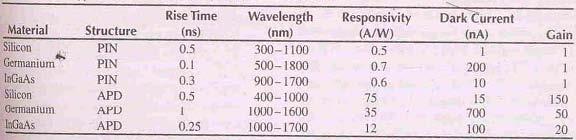
102 ILD versus LED Advantages: more focussed radiation pattern; smaller Fiber much higher radiant power; longer span faster ON, OFF time; higher bit rates possible monochromatic light; reduces dispersion Disadvantages: much more expensive higher temperature; shorter lifespan
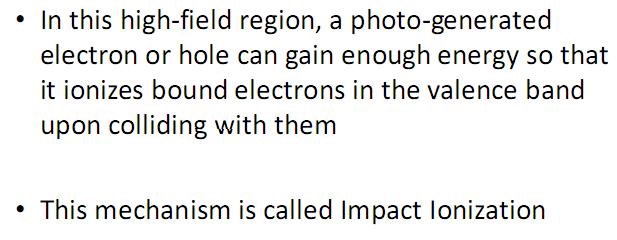
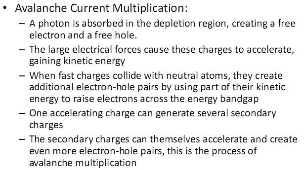
103 Light Detectors PIN Diodes photons are absorbed in the intrinsic layer sufficient energy is added to generate carriers in the depletion layer for current to flow through the device Avalanche Photodiodes (APD) photogenerated electrons are accelerated by relatively large reverse voltage and collide with other atoms to produce more free electrons avalanche multiplication effect makes APD more sensitive but also more noisy than PIN diodes

104 That's it!!!!
105 Photodiodes
106 Light Detectors The role of an optical receiver is to convert the optical signal back into electrical form and recover the data transmitted through the light wave system Its main component is a photodetector that converts light into electricity through the photoelectric effect 2

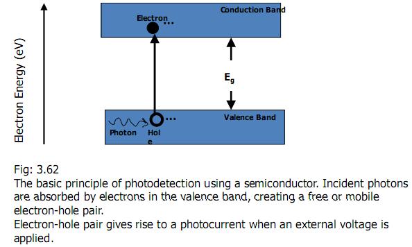
107 Principles of Photo detection
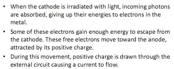
108 Vacuum Photodiode
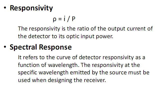
109 Detector Properties
110 Detector Properties
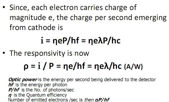
111 Detector Properties
112
113 Detector Properties
114 Semiconductor PD
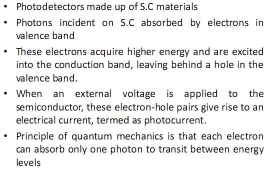
115 PD principles
116 PD Materials

117 PD principles
118 PD principles
119 PD principles
120
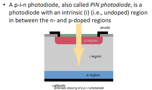
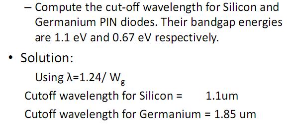
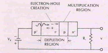
121 PIN Photodiode
122 PIN Photodiode
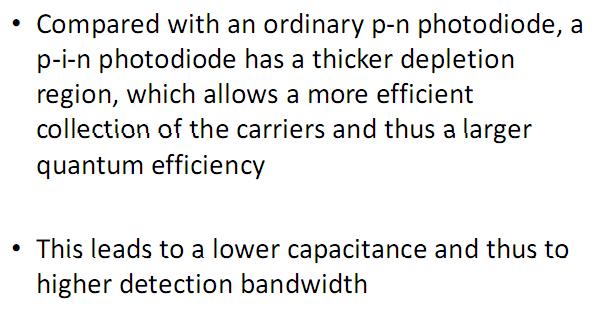
123 PIN Photodiode
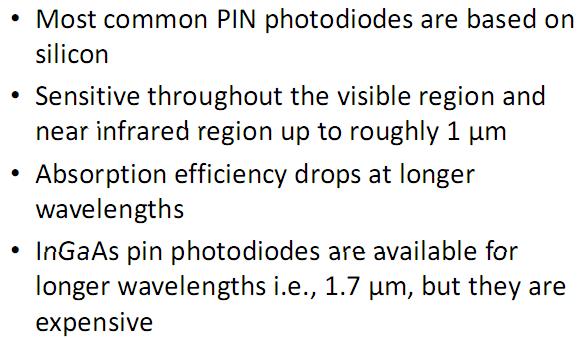
124 PIN Photodiode
125 PIN Photodiode
126
127 Avalanche Photodiode
128 Avalanche Photodiode

129 Avalanche Photodiode
130 Avalanche Photodiode
131 Avalanche Photodiode
132 Avalanche Photodiode
133 Avalanche Photodiode
134 Avalanche Photodiode
135 Avalanche Photodiode
136 Thank You
is a method of transmitting information from one place to another by sending light through an optical fiber. The light forms an electromagnetic
 is a method of transmitting information from one place to another by sending light through an optical fiber. The light forms an electromagnetic carrier wave that is modulated to carry information. The
Basic concepts. Optical Sources (b) Optical Sources (a) Requirements for light sources (b) Requirements for light sources (a)
 Optical Sources (a) Requirements for light sources (b) Requirements for light sources (a)") Optical Sources (a) Optical Sources (b) The main light sources used with fibre optic systems are: Light-emitting diodes (LEDs) Semiconductor lasers (diode lasers) Fibre laser and other compact solid-state
Optical Sources (a) Optical Sources (b) The main light sources used with fibre optic systems are: Light-emitting diodes (LEDs) Semiconductor lasers (diode lasers) Fibre laser and other compact solid-state
Optodevice Data Book ODE I. Rev.9 Mar Opnext Japan, Inc.
 Optodevice Data Book ODE-408-001I Rev.9 Mar. 2003 Opnext Japan, Inc. Section 1 Operating Principles 1.1 Operating Principles of Laser Diodes (LDs) and Infrared Emitting Diodes (IREDs) 1.1.1 Emitting Principles
Optical Amplifiers Photonics and Integrated Optics (ELEC-E3240) Zhipei Sun Photonics Group Department of Micro- and Nanosciences Aalto University
 Zhipei Sun Photonics Group Department of Micro- and Nanosciences Aalto University") Photonics Group Department of Micro- and Nanosciences Aalto University Optical Amplifiers Photonics and Integrated Optics (ELEC-E3240) Zhipei Sun Last Lecture Topics Course introduction Ray optics & optical
Photonics Group Department of Micro- and Nanosciences Aalto University Optical Amplifiers Photonics and Integrated Optics (ELEC-E3240) Zhipei Sun Last Lecture Topics Course introduction Ray optics & optical
Absorption: in an OF, the loss of Optical power, resulting from conversion of that power into heat.
 Absorption: in an OF, the loss of Optical power, resulting from conversion of that power into heat. Scattering: The changes in direction of light confined within an OF, occurring due to imperfection in
Optical Communications and Networks - Review and Evolution (OPTI 500) Massoud Karbassian
 Massoud Karbassian") Optical Communications and Networks - Review and Evolution (OPTI 500) Massoud Karbassian m.karbassian@arizona.edu Contents Optical Communications: Review Optical Communications and Photonics Why Photonics?
Optical Communications and Networks - Review and Evolution (OPTI 500) Massoud Karbassian m.karbassian@arizona.edu Contents Optical Communications: Review Optical Communications and Photonics Why Photonics?
Lecture 6 Fiber Optical Communication Lecture 6, Slide 1
 Lecture 6 Optical transmitters Photon processes in light matter interaction Lasers Lasing conditions The rate equations CW operation Modulation response Noise Light emitting diodes (LED) Power Modulation
Optical Communications and Networks - Review and Evolution (OPTI 500) Massoud Karbassian
 Massoud Karbassian") Optical Communications and Networks - Review and Evolution (OPTI 500) Massoud Karbassian m.karbassian@arizona.edu Contents Optical Communications: Review Optical Communications and Photonics Why Photonics?
Optical Communications and Networks - Review and Evolution (OPTI 500) Massoud Karbassian m.karbassian@arizona.edu Contents Optical Communications: Review Optical Communications and Photonics Why Photonics?
Elements of Optical Networking
 Bruckner Elements of Optical Networking Basics and practice of optical data communication With 217 Figures, 13 Tables and 93 Exercises Translated by Patricia Joliet VIEWEG+ TEUBNER VII Content Preface
SYLLABUS Optical Fiber Communication
 SYLLABUS Optical Fiber Communication Subject Code : IA Marks : 25 No. of Lecture Hrs/Week : 04 Exam Hours : 03 Total no. of Lecture Hrs. : 52 Exam Marks : 100 UNIT - 1 PART - A OVERVIEW OF OPTICAL FIBER
Chapter 3 OPTICAL SOURCES AND DETECTORS
 Chapter 3 OPTICAL SOURCES AND DETECTORS 3. Optical sources and Detectors 3.1 Introduction: The success of light wave communications and optical fiber sensors is due to the result of two technological breakthroughs.
Introduction Fundamentals of laser Types of lasers Semiconductor lasers
 ECE 5368 Introduction Fundamentals of laser Types of lasers Semiconductor lasers Introduction Fundamentals of laser Types of lasers Semiconductor lasers How many types of lasers? Many many depending on
Optical fibre. Principle and applications
 Optical fibre Principle and applications Circa 2500 B.C. Earliest known glass Roman times-glass drawn into fibers Venice Decorative Flowers made of glass fibers 1609-Galileo uses optical telescope 1626-Snell
ECE 340 Lecture 29 : LEDs and Lasers Class Outline:
 ECE 340 Lecture 29 : LEDs and Lasers Class Outline: Light Emitting Diodes Lasers Semiconductor Lasers Things you should know when you leave Key Questions What is an LED and how does it work? How does a
Key Questions. What is an LED and how does it work? How does a laser work? How does a semiconductor laser work? ECE 340 Lecture 29 : LEDs and Lasers
 Things you should know when you leave Key Questions ECE 340 Lecture 29 : LEDs and Class Outline: What is an LED and how does it How does a laser How does a semiconductor laser How do light emitting diodes
Optical Amplifiers. Continued. Photonic Network By Dr. M H Zaidi
 Optical Amplifiers Continued EDFA Multi Stage Designs 1st Active Stage Co-pumped 2nd Active Stage Counter-pumped Input Signal Er 3+ Doped Fiber Er 3+ Doped Fiber Output Signal Optical Isolator Optical
Chapter 12: Optical Amplifiers: Erbium Doped Fiber Amplifiers (EDFAs)
") Chapter 12: Optical Amplifiers: Erbium Doped Fiber Amplifiers (EDFAs) Prof. Dr. Yaocheng SHI ( 时尧成 ) yaocheng@zju.edu.cn http://mypage.zju.edu.cn/yaocheng 1 Traditional Optical Communication System Loss
Chapter 12: Optical Amplifiers: Erbium Doped Fiber Amplifiers (EDFAs) Prof. Dr. Yaocheng SHI ( 时尧成 ) yaocheng@zju.edu.cn http://mypage.zju.edu.cn/yaocheng 1 Traditional Optical Communication System Loss
CONTENTS. Chapter 1 Wave Nature of Light 19
 CONTENTS Chapter 1 Wave Nature of Light 19 1.1 Light Waves in a Homogeneous Medium 19 A. Plane Electromagnetic Wave 19 B. Maxwell's Wave Equation and Diverging Waves 22 Example 1.1.1 A diverging laser
Introduction to Fiber Optics
 Introduction to Fiber Optics Dr. Anurag Srivastava Atal Bihari Vajpayee Indian Institute of Information Technology and Manegement, Gwalior Milestones in Electrical Communication 1838 Samuel F.B. Morse
Lecture 9 External Modulators and Detectors
 Optical Fibres and Telecommunications Lecture 9 External Modulators and Detectors Introduction Where are we? A look at some real laser diodes. External modulators Mach-Zender Electro-absorption modulators
Optical Fibers p. 1 Basic Concepts p. 1 Step-Index Fibers p. 2 Graded-Index Fibers p. 4 Design and Fabrication p. 6 Silica Fibers p.
 Preface p. xiii Optical Fibers p. 1 Basic Concepts p. 1 Step-Index Fibers p. 2 Graded-Index Fibers p. 4 Design and Fabrication p. 6 Silica Fibers p. 6 Plastic Optical Fibers p. 9 Microstructure Optical
Photonics and Fiber Optics
 1 UNIT V Photonics and Fiber Optics Part-A 1. What is laser? LASER is the acronym for Light Amplification by Stimulated Emission of Radiation. The absorption and emission of light by materials has been
Examination Optoelectronic Communication Technology. April 11, Name: Student ID number: OCT1 1: OCT 2: OCT 3: OCT 4: Total: Grade:
 Examination Optoelectronic Communication Technology April, 26 Name: Student ID number: OCT : OCT 2: OCT 3: OCT 4: Total: Grade: Declaration of Consent I hereby agree to have my exam results published on
The absorption of the light may be intrinsic or extrinsic
 Attenuation Fiber Attenuation Types 1- Material Absorption losses 2- Intrinsic Absorption 3- Extrinsic Absorption 4- Scattering losses (Linear and nonlinear) 5- Bending Losses (Micro & Macro) Material
Ph 77 ADVANCED PHYSICS LABORATORY ATOMIC AND OPTICAL PHYSICS
 Ph 77 ADVANCED PHYSICS LABORATORY ATOMIC AND OPTICAL PHYSICS Diode Laser Characteristics I. BACKGROUND Beginning in the mid 1960 s, before the development of semiconductor diode lasers, physicists mostly
S Optical Networks Course Lecture 2: Essential Building Blocks
 S-72.3340 Optical Networks Course Lecture 2: Essential Building Blocks Edward Mutafungwa Communications Laboratory, Helsinki University of Technology, P. O. Box 2300, FIN-02015 TKK, Finland Tel: +358 9
Optical behavior. Reading assignment. Topic 10
 Reading assignment Optical behavior Topic 10 Askeland and Phule, The Science and Engineering of Materials, 4 th Ed.,Ch. 0. Shackelford, Materials Science for Engineers, 6 th Ed., Ch. 16. Chung, Composite
COM 46: ADVANCED COMMUNICATIONS jfm 07 FIBER OPTICS
 FIBER OPTICS Fiber optics is a unique transmission medium. It has some unique advantages over conventional communication media, such as copper wire, microwave or coaxial cables. The major advantage is
Contents for this Presentation. Multi-Service Transport
 Contents for this Presentation SDH/DWDM based Multi-Service Transport Platform by Khurram Shahzad ad Brief Contents Description for this of Presentation the Project Development of a Unified Transport Platform
MAHALAKSHMI ENGINEERING COLLEGE TIRUCHIRAPALLI
 MAHALAKSHMI ENGINEERING COLLEGE TIRUCHIRAPALLI - 621213 DEPARTMENT : ECE SUBJECT NAME : OPTICAL COMMUNICATION & NETWORKS SUBJECT CODE : EC 2402 UNIT III: SOURCES AND DETECTORS PART -A (2 Marks) 1. What
Functional Materials. Optoelectronic devices
 Functional Materials Lecture 2: Optoelectronic materials and devices (inorganic). Photonic materials Optoelectronic devices Light-emitting diode (LED) displays Photodiode and Solar cell Photoconductive
Fiber-Optic Communication Systems
 Fiber-Optic Communication Systems Second Edition GOVIND P. AGRAWAL The Institute of Optics University of Rochester Rochester, NY A WILEY-iNTERSCIENCE PUBLICATION JOHN WILEY & SONS, INC. NEW YORK / CHICHESTER
Optical communications
 Optical communications Components and enabling technologies Optical networking Evolution of optical networking: road map SDH = Synchronous Digital Hierarchy SONET = Synchronous Optical Network SDH SONET
Review of Semiconductor Physics
 Review of Semiconductor Physics k B 1.38 u 10 23 JK -1 a) Energy level diagrams showing the excitation of an electron from the valence band to the conduction band. The resultant free electron can freely
Fiberoptic Communication Systems By Dr. M H Zaidi. Optical Amplifiers
 Optical Amplifiers Optical Amplifiers Optical signal propagating in fiber suffers attenuation Optical power level of a signal must be periodically conditioned Optical amplifiers are a key component in
Optical Fiber Communication
 A Seminar report On Optical Fiber Communication Submitted in partial fulfillment of the requirement for the award of degree Of Mechanical SUBMITTED TO: www.studymafia.org SUBMITTED BY: www.studymafia.org
Fiber Optic Communications Communication Systems
 INTRODUCTION TO FIBER-OPTIC COMMUNICATIONS A fiber-optic system is similar to the copper wire system in many respects. The difference is that fiber-optics use light pulses to transmit information down
Figure 1. Schematic diagram of a Fabry-Perot laser.
 Figure 1. Schematic diagram of a Fabry-Perot laser. Figure 1. Shows the structure of a typical edge-emitting laser. The dimensions of the active region are 200 m m in length, 2-10 m m lateral width and
Optical Communications and Networking 朱祖勍. Oct. 9, 2017
 Optical Communications and Networking Oct. 9, 2017 1 Optical Amplifiers In optical communication systems, the optical signal from the transmitter are attenuated by the fiber and other passive components
OPTICAL NETWORKS. Building Blocks. A. Gençata İTÜ, Dept. Computer Engineering 2005
 OPTICAL NETWORKS Building Blocks A. Gençata İTÜ, Dept. Computer Engineering 2005 Introduction An introduction to WDM devices. optical fiber optical couplers optical receivers optical filters optical amplifiers
Lecture 4 INTEGRATED PHOTONICS
 Lecture 4 INTEGRATED PHOTONICS What is photonics? Photonic applications use the photon in the same way that electronic applications use the electron. Devices that run on light have a number of advantages
Optical Transmission Fundamentals
 Optical Transmission Fundamentals F. Vasey, CERN-EP-ESE Context Technology HEP Specifics 12 Nov 2018 0 Context: Bandwidth Demand Internet traffic is growing at ~Moore s law Global interconnection bandwidth
Modulation of light. Direct modulation of sources Electro-absorption (EA) modulators
 modulators") Modulation of light Direct modulation of sources Electro-absorption (EA) modulators Why Modulation A communication link is established by transmission of information reliably Optical modulation is embedding
Modulation of light Direct modulation of sources Electro-absorption (EA) modulators Why Modulation A communication link is established by transmission of information reliably Optical modulation is embedding
Introduction Fundamental of optical amplifiers Types of optical amplifiers
 ECE 6323 Introduction Fundamental of optical amplifiers Types of optical amplifiers Erbium-doped fiber amplifiers Semiconductor optical amplifier Others: stimulated Raman, optical parametric Advanced application:
2 in the multipath dispersion of the optical fibre. (b) Discuss the merits and drawbacks of cut bouls method of measurement of alternation.
 Discuss the merits and drawbacks of cut bouls method of measurement of alternation.") B.TECH IV Year I Semester (R09) Regular Examinations, November 2012 1 (a) Derive an expression for multiple time difference tt 2 in the multipath dispersion of the optical fibre. (b) Discuss the merits
B.TECH IV Year I Semester (R09) Regular Examinations, November 2012 1 (a) Derive an expression for multiple time difference tt 2 in the multipath dispersion of the optical fibre. (b) Discuss the merits
UNIT - 7 WDM CONCEPTS AND COMPONENTS
 UNIT - 7 WDM CONCEPTS AND COMPONENTS WDM concepts, overview of WDM operation principles, WDM standards, Mach-Zehender interferometer, multiplexer, Isolators and circulators, direct thin film filters, active
Semiconductor Optical Communication Components and Devices Lecture 18: Introduction to Diode Lasers - I
 Semiconductor Optical Communication Components and Devices Lecture 18: Introduction to Diode Lasers - I Prof. Utpal Das Professor, Department of lectrical ngineering, Laser Technology Program, Indian Institute
Laser Diode. Photonic Network By Dr. M H Zaidi
 Laser Diode Light emitters are a key element in any fiber optic system. This component converts the electrical signal into a corresponding light signal that can be injected into the fiber. The light emitter
Optical switches. Switching Technology S Optical switches
 Optical switches Switching Technology S38.165 http://www.netlab.hut.fi/opetus/s38165 13-1 Optical switches Components and enabling technologies Contention resolution Optical switching schemes 13-2 1 Components
FIBER OPTICS. Prof. R.K. Shevgaonkar. Department of Electrical Engineering. Indian Institute of Technology, Bombay. Lecture: 18.
 FIBER OPTICS Prof. R.K. Shevgaonkar Department of Electrical Engineering Indian Institute of Technology, Bombay Lecture: 18 Optical Sources- Introduction to LASER Diodes Fiber Optics, Prof. R.K. Shevgaonkar,
Photonics and Optical Communication
 Photonics and Optical Communication (Course Number 300352) Spring 2007 Dr. Dietmar Knipp Assistant Professor of Electrical Engineering http://www.faculty.iu-bremen.de/dknipp/ 1 Photonics and Optical Communication
LEDs, Photodetectors and Solar Cells
 LEDs, Photodetectors and Solar Cells Chapter 7 (Parker) ELEC 424 John Peeples Why the Interest in Photons? Answer: Momentum and Radiation High electrical current density destroys minute polysilicon and
Optical Fiber. n 2. n 1. θ 2. θ 1. Critical Angle According to Snell s Law
 ECE 271 Week 10 Critical Angle According to Snell s Law n 1 sin θ 1 = n 1 sin θ 2 θ 1 and θ 2 are angle of incidences The angle of incidence is measured with respect to the normal at the refractive boundary
UNIT What is splicing? Explain about fusion splicing? Ans: Splicing
 UNIT 4 1. What is splicing? Explain about fusion splicing? Ans: Splicing A permanent joint formed between two individual optical fibers in the field is known as splicing. The fiber splicing is used to
Chapter 18: Fiber Optic and Laser Technology
 Chapter 18: Fiber Optic and Laser Technology Chapter 18 Objectives At the conclusion of this chapter, the reader will be able to: Describe the construction of fiber optic cable. Describe the propagation
White Paper Laser Sources For Optical Transceivers. Giacomo Losio ProLabs Head of Technology
 White Paper Laser Sources For Optical Transceivers Giacomo Losio ProLabs Head of Technology September 2014 Laser Sources For Optical Transceivers Optical transceivers use different semiconductor laser
Optical Fibre Amplifiers Continued
 1 Optical Fibre Amplifiers Continued Stavros Iezekiel Department of Electrical and Computer Engineering University of Cyprus ECE 445 Lecture 09 Fall Semester 2016 2 ERBIUM-DOPED FIBRE AMPLIFIERS BASIC
Luminous Equivalent of Radiation
 Intensity vs λ Luminous Equivalent of Radiation When the spectral power (p(λ) for GaP-ZnO diode has a peak at 0.69µm) is combined with the eye-sensitivity curve a peak response at 0.65µm is obtained with
Optical Communication and Networks M.N. Bandyopadhyay
 Optical Communication and Networks M.N. Bandyopadhyay Director National Institute of Technology (NIT) Calicut Delhi-110092 2014 OPTICAL COMMUNICATION AND NETWORKS M.N. Bandyopadhyay 2014 by PHI Learning
Optical Communications and Networking 朱祖勍. Sept. 25, 2017
 Optical Communications and Networking Sept. 25, 2017 Lecture 4: Signal Propagation in Fiber 1 Nonlinear Effects The assumption of linearity may not always be valid. Nonlinear effects are all related to
Vertical External Cavity Surface Emitting Laser
 Chapter 4 Optical-pumped Vertical External Cavity Surface Emitting Laser The booming laser techniques named VECSEL combine the flexibility of semiconductor band structure and advantages of solid-state
Optical Sources and Detectors
 Optical Sources and Detectors 1. Optical Sources Optical transmitter coverts electrical input signal into corresponding optical signal. The optical signal is then launched into the fiber. Optical source
Robert G. Hunsperger. Integrated Optics. Theory and Technology. Sixth Edition. 4ü Spri rineer g<
 Robert G. Hunsperger Integrated Optics Theory and Technology Sixth Edition 4ü Spri rineer g< 1 Introduction 1 1.1 Advantages of Integrated Optics 2 1.1.1 Comparison of Optical Fibers with Other Interconnectors
CHAPTER 4 RESULTS. 4.1 Introduction
 CHAPTER 4 RESULTS 4.1 Introduction In this chapter focus are given more on WDM system. The results which are obtained mainly from the simulation work are presented. In simulation analysis, the study will
The electric field for the wave sketched in Fig. 3-1 can be written as
 ELECTROMAGNETIC WAVES Light consists of an electric field and a magnetic field that oscillate at very high rates, of the order of 10 14 Hz. These fields travel in wavelike fashion at very high speeds.
OFC SYSTEM: Design Considerations. BC Choudhary, Professor NITTTR, Sector 26, Chandigarh.
 OFC SYSTEM: Design Considerations BC Choudhary, Professor NITTTR, Sector 26, Chandigarh. OFC point-to-point Link Transmitter Electrical to Optical Conversion Coupler Optical Fiber Coupler Optical to Electrical
InP-based Waveguide Photodetector with Integrated Photon Multiplication
 InP-based Waveguide Photodetector with Integrated Photon Multiplication D.Pasquariello,J.Piprek,D.Lasaosa,andJ.E.Bowers Electrical and Computer Engineering Department University of California, Santa Barbara,
Optical Digital Transmission Systems. Xavier Fernando ADROIT Lab Ryerson University
 Optical Digital Transmission Systems Xavier Fernando ADROIT Lab Ryerson University Overview In this section we cover point-to-point digital transmission link design issues (Ch8): Link power budget calculations
Guided Propagation Along the Optical Fiber. Xavier Fernando Ryerson Comm. Lab
 Guided Propagation Along the Optical Fiber Xavier Fernando Ryerson Comm. Lab The Nature of Light Quantum Theory Light consists of small particles (photons) Wave Theory Light travels as a transverse electromagnetic
UNIT-II : SIGNAL DEGRADATION IN OPTICAL FIBERS
 UNIT-II : SIGNAL DEGRADATION IN OPTICAL FIBERS The Signal Transmitting through the fiber is degraded by two mechanisms. i) Attenuation ii) Dispersion Both are important to determine the transmission characteristics
Lecture 4 Fiber Optical Communication Lecture 4, Slide 1
 Lecture 4 Optical transmitters Photon processes in light matter interaction Lasers Lasing conditions The rate equations CW operation Modulation response Noise Light emitting diodes (LED) Power Modulation
Industrial Automation
 OPTICAL FIBER. SINGLEMODE OR MULTIMODE It is important to understand the differences between singlemode and multimode fiber optics before selecting one or the other at the start of a project. Its different
OPTICAL COMMUNICATIONS S
 OPTICAL COMMUNICATIONS S-108.3110 1 Course program 1. Introduction and Optical Fibers 2. Nonlinear Effects in Optical Fibers 3. Fiber-Optic Components 4. Transmitters and Receivers 5. Fiber-Optic Measurements
Optical Fiber Technology. Photonic Network By Dr. M H Zaidi
 Optical Fiber Technology Numerical Aperture (NA) What is numerical aperture (NA)? Numerical aperture is the measure of the light gathering ability of optical fiber The higher the NA, the larger the core
Light Sources, Modulation, Transmitters and Receivers
 Optical Fibres and Telecommunications Light Sources, Modulation, Transmitters and Receivers Introduction Previous section looked at Fibres. How is light generated in the first place? How is light modulated?
UNIT-III SOURCES AND DETECTORS. According to the shape of the band gap as a function of the momentum, semiconductors are classified as
 UNIT-III SOURCES AND DETECTORS DIRECT AND INDIRECT BAND GAP SEMICONDUCTORS: According to the shape of the band gap as a function of the momentum, semiconductors are classified as 1. Direct band gap semiconductors
Optical MEMS in Compound Semiconductors Advanced Engineering Materials, Cal Poly, SLO November 16, 2007
 Optical MEMS in Compound Semiconductors Advanced Engineering Materials, Cal Poly, SLO November 16, 2007 Outline Brief Motivation Optical Processes in Semiconductors Reflectors and Optical Cavities Diode
Photonics and Optical Communication Spring 2005
 Photonics and Optical Communication Spring 2005 Final Exam Instructor: Dr. Dietmar Knipp, Assistant Professor of Electrical Engineering Name: Mat. -Nr.: Guidelines: Duration of the Final Exam: 2 hour You
Chapter 8. Wavelength-Division Multiplexing (WDM) Part II: Amplifiers
 Part II: Amplifiers") Chapter 8 Wavelength-Division Multiplexing (WDM) Part II: Amplifiers Introduction Traditionally, when setting up an optical link, one formulates a power budget and adds repeaters when the path loss exceeds
Chapter 8 Wavelength-Division Multiplexing (WDM) Part II: Amplifiers Introduction Traditionally, when setting up an optical link, one formulates a power budget and adds repeaters when the path loss exceeds
Fundamentals of Laser
 SMR 1826-3 Preparatory School to the Winter College on Fibre 5-9 February 2007 Fundamentals of Laser Imrana Ashraf Zahid Quaid-i-Azam University Islamabad Pakistan Fundamentals of Laser Dr. Imrana Ashraf
R. J. Jones Optical Sciences OPTI 511L Fall 2017
 R. J. Jones Optical Sciences OPTI 511L Fall 2017 Semiconductor Lasers (2 weeks) Semiconductor (diode) lasers are by far the most widely used lasers today. Their small size and properties of the light output
Performance Evaluation of 32 Channel DWDM System Using Dispersion Compensation Unit at Different Bit Rates
 Performance Evaluation of 32 Channel DWDM System Using Dispersion Compensation Unit at Different Bit Rates Simarpreet Kaur Gill 1, Gurinder Kaur 2 1Mtech Student, ECE Department, Rayat- Bahra University,
Optical systems have carrier frequencies of ~100 THz. This corresponds to wavelengths from µm.
 Introduction A communication system transmits information form one place to another. This could be from one building to another or across the ocean(s). Many systems use an EM carrier wave to transmit information.
Fiber Optic Principles. Oct-09 1
 Fiber Optic Principles Oct-09 1 Fiber Optic Basics Optical fiber Active components Attenuation Power budget Bandwidth Oct-09 2 Reference www.flukenetworks.com/fiber Handbook Fiber Optic Technologies (Vivec
Introduction and concepts Types of devices
 ECE 6323 Introduction and concepts Types of devices Passive splitters, combiners, couplers Wavelength-based devices for DWDM Modulator/demodulator (amplitude and phase), compensator (dispersion) Others:
Trends in Optical Transceivers:
 Trends in Optical Transceivers: Light sources for premises networks Peter Ronco Corning Optical Fiber Asst. Product Line Manager Premises Fibers January 24, 2006 Outline: Introduction: Transceivers and
ECEN689: Special Topics in Optical Interconnects Circuits and Systems Spring 2016
 ECEN689: Special Topics in Optical Interconnects Circuits and Systems Spring 016 Lecture 7: Transmitter Analysis Sam Palermo Analog & Mixed-Signal Center Texas A&M University Optical Modulation Techniques
Optoelectronics ELEC-E3210
 Optoelectronics ELEC-E3210 Lecture 4 Spring 2016 Outline 1 Lateral confinement: index and gain guiding 2 Surface emitting lasers 3 DFB, DBR, and C3 lasers 4 Quantum well lasers 5 Mode locking P. Bhattacharya:
Ph.D. Course Spring Wireless Communications. Wirebound Communications
 Ph.D. Course Spring 2005 Danyo Danev associate professor Div. Data Transmission, Dept. Electrical Engineering Linköping University SWEDEN Wireless Communications Radio transmissions Mobile telephony Satellite
Chapter 9 GUIDED WAVE OPTICS
 [Reading Assignment, Hecht 5.6] Chapter 9 GUIDED WAVE OPTICS Optical fibers The step index circular waveguide is the most common fiber design for optical communications plastic coating (sheath) core cladding
Guided Propagation Along the Optical Fiber. Xavier Fernando Ryerson University
 Guided Propagation Along the Optical Fiber Xavier Fernando Ryerson University The Nature of Light Quantum Theory Light consists of small particles (photons) Wave Theory Light travels as a transverse electromagnetic
Transmitting Light: Fiber-optic and Free-space Communications Holography
 1 Lecture 9 Transmitting Light: Fiber-optic and Free-space Communications Holography 2 Wireless Phone Calls http://havilandtelconews.com/2011/10/the-reality-behind-wireless-networks/ 3 Undersea Cable and
Lecture 5 Transmission. Physical and Datalink Layers: 3 Lectures
 Lecture 5 Transmission Peter Steenkiste School of Computer Science Department of Electrical and Computer Engineering Carnegie Mellon University 15-441 Networking, Spring 2004 http://www.cs.cmu.edu/~prs/15-441
Comparative Study of an Optical Link with PIN and APD as Photo-Detector Preetam Jain 1, Dr Lochan Jolly 2
 Comparative Study of an Optical Link with PIN and APD as Photo-Detector Preetam Jain 1, Dr Lochan Jolly 2 1 ME EXTC Student Thakur College of Engineering and Technology 2 Professor Thakur College of Engineering
WDM Concept and Components. EE 8114 Course Notes
 WDM Concept and Components EE 8114 Course Notes Part 1: WDM Concept Evolution of the Technology Why WDM? Capacity upgrade of existing fiber networks (without adding fibers) Transparency:Each optical channel
Module 16 : Integrated Optics I
 Module 16 : Integrated Optics I Lecture : Integrated Optics I Objectives In this lecture you will learn the following Introduction Electro-Optic Effect Optical Phase Modulator Optical Amplitude Modulator
Optical Receivers Theory and Operation
 Optical Receivers Theory and Operation Photo Detectors Optical receivers convert optical signal (light) to electrical signal (current/voltage) Hence referred O/E Converter Photodetector is the fundamental
Lecture 18: Photodetectors
 Lecture 18: Photodetectors Contents 1 Introduction 1 2 Photodetector principle 2 3 Photoconductor 4 4 Photodiodes 6 4.1 Heterojunction photodiode.................... 8 4.2 Metal-semiconductor photodiode................
William Stallings Data and Computer Communications 7 th Edition. Chapter 4 Transmission Media
 William Stallings Data and Computer Communications 7 th Edition Chapter 4 Transmission Media Overview Guided - wire Unguided - wireless Characteristics and quality determined by medium and signal For guided,
DWDM FILTERS; DESIGN AND IMPLEMENTATION
 DWDM FILTERS; DESIGN AND IMPLEMENTATION 1 OSI REFERENCE MODEL PHYSICAL OPTICAL FILTERS FOR DWDM SYSTEMS 2 AGENDA POINTS NEED CHARACTERISTICS CHARACTERISTICS CLASSIFICATION TYPES PRINCIPLES BRAGG GRATINGS