Chapter 12: Optical Amplifiers: Erbium Doped Fiber Amplifiers (EDFAs)
|
|
|
- Vivien Robertson
- 5 years ago
- Views:
Transcription
 yaocheng@zju.edu.cn http://mypage.zju.edu.cn/yaocheng 1")
1 Chapter 12: Optical Amplifiers: Erbium Doped Fiber Amplifiers (EDFAs) Prof. Dr. Yaocheng SHI ( 时尧成 ) yaocheng@zju.edu.cn 1

2 Traditional Optical Communication System Loss compensation: Repeaters at every km 2
3 Repeaters 3R (regeneration with retiming and reshaping) produces a fresh copy of received signal 2R (regeneration with reshaping) 1R (regeneration) Repeaters and amplifiers Repeaters do not work for fiber-optic networks, where many transmitters send signals to many receivers at different bit rates and in different formats Optical amplifier Support any bit rate and signal format (transparent) Support the entire region of wavelengths Increase the capacity of fiberoptic links by using WDM Provide the capability of alloptical networks, not just point-to-point links 3

4 Optically Amplified Systems EDFA = Erbium Doped fiber Amplifier 4
5 Amplifier types and applications The main types of optical amplifiers: Doped fiber amplifier (eg. EDFA) Semiconductor optical amplifier (SOA) Fiber Raman amplifier Fiber Brillouin amplifer Fiber optical parametric amplifier (FOPA) For overcoming or compensating for the optical loss Important properties to consider: Gain and gain bandwidth Gain flatness and saturation Noise 5

6 Common characteristics of all amplifiers 6

7 Comparison of real and ideal amplifiers 7

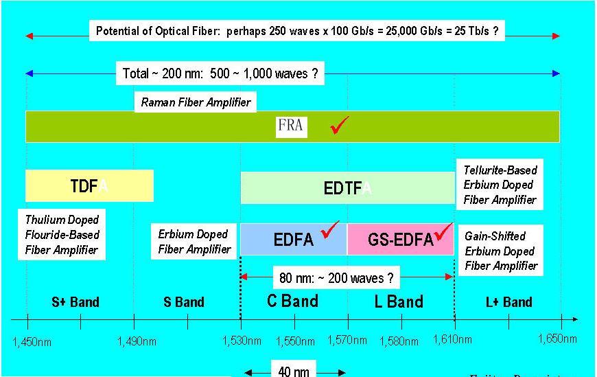
8 Operating band of rare-earth doped fiber amplifiers 8

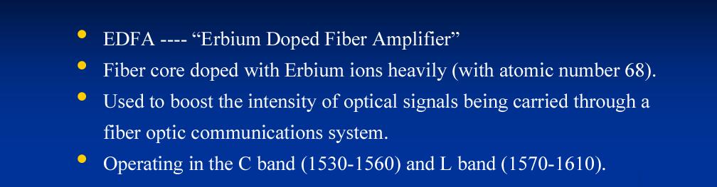
9 What is EDFA? Why EDFA? 9
10 Basic EDF Amplifier Design Erbium-doped fiber amplifier (EDFA) most common Commercially available since the early 1990 s Works best in the range 1530 to 1565 nm Gain up to 30 db (1000 photons out per photon in!) Optically transparent Unlimited RF bandwidth Wavelength transparent 10

11 Erbium Doped Fiber Amplifier A pump optical signal is added to an input signal by a WDM coupler Within a length of doped fiber part of the pump energy is transferred to the input signal by stimulated emission For operation circa 1550 nm the fiber dopant is Erbium Pump wavelength is 980 nm or 1480 nm, pump power circa 50 mw Gains of db possible 11

12 Interior of an Erbium Doped fiber Amplifier (EDFA) WDM fiber coupler Pump laser Erbium doped fiber loop fiber input/output 12

13 Operation of an EDFA 13

14 Erbium energy levels and pump sources 14
 980 or 1480 nm Pump")

15 Er +3 Energy Levels Pump: (Optical) 980 or 1480 nm Pump power >5 mw Emission: m Long living upper state (10 ms) Gain 30 db 15
16 EDFA Operation A (relatively) high-powered beam of light is mixed with the input signal using a wavelength selective coupler. The mixed light is guided into a section of fiber with erbium ions included in the core. This high-powered light beam excites the erbium ions to their higher-energy state. When the photons belonging to the signal (at a different wavelength from the pump light) meet the excited erbium atoms, the erbium atoms give up some of their energy to the signal and return to their lower-energy state. A significant point is that the erbium gives up its energy in the form of additional photons which are exactly in the same phase and direction as the signal being amplified. There is usually an isolator placed at the output. Why? 16

17 Structures of EDFAs Components: Er-doped fiber Pump laser WDM coupler Isolator Filter 17

18 Output Spectra If the input signal is turned off then you measure a big ASE. If it is turned on then you measure a big signal. Why? 18
19 Amplified Spontaneous Emission Erbium randomly emits photons between 1520 and 1570 nm Spontaneous emission (SE) is not polarized or coherent Like any photon, SE stimulates emission of other photons With no input signal, eventually all optical energy is consumed into amplified spontaneous emission Input signal(s) consume metastable electrons much less ASE Random spontaneous emission (SE) Amplification along fiber Amplified spontaneous emission (ASE) 19
20 Gain in EDFAs The amplification achieved in a EDFA is due to the Er-ions returning to the ground state and then emitting the excessive energy as coherent light when stimulated by the incoming light. Definition: Gain is the ratio of output to input light power Gain P / P out in 10 Gain( db) 10log ( P / P ) Gain ( P P ) / P Gain( db) 10log 10[( P P ) / P ] out ASE in Gain coefficient: db/m Gain bandwidth: From about 1500 nm to 1600 nm C-band ( nm): most EDFA L-band ( nm): depress four-wave mixing out in out ASE in 20
21 Flattening of the Gain Curve Techniques Operating the device at 77 K. This produces a much better (flatter) gain curve but it's not all that practical. Introducing other dopant materials (such as aluminium or ytterbium) along with the erbium into the fiber core. Amplifier length is another factor influencing the flatness of the gain curve. Controlling the pump power (through a feedback loop) is routine to reduce amplified spontaneous emission. Adding an extra WDM channel locally at the amplifier ( gain clamping ). Manipulating the shape of the fiber waveguide within the amplifier. At the systems level there are other things that can be done to compensate: Using blazed fiber Bragg gratings as filters to reduce the peaks in the response curve. To transmit different WDM channels at different power levels to compensate for later amplifier gain characteristics. 21
22 Gain in EDFAs Gain flatness (for multiple channel systems) Equalization filter (eg. long-period fiber grating) 22
 The higher the pump power, the more excited Er-ions and the higher saturation power. Gain vs. fiber length The typical length of an active fiber is from 20 to 50 meters.")
23 Gain saturation Gain in EDFAs Gain is decreased because of the depletion of the population of intermediate level with a high-power input signal Gain saturation determines the maximum output power (saturated output power) The higher the pump power, the more excited Er-ions and the higher saturation power. Gain vs. fiber length The typical length of an active fiber is from 20 to 50 meters. An active fiber has an optimal length (doping concentration, gain bandwidth and shape). 23
24 EDFA Behaviour at Gain Saturation There are two main differences between the behaviour of electronic amplifiers and of EDFAs in gain saturation: 1) As input power is increased on the EDFA the total gain of the amplifier increases slowly. An electronic amplifier operates relatively linearly until its gain saturates and then it just produces all it can. This means that an electronic amplifier operated near saturation introduces significant distortions into the signal (it just clips the peaks off). 2) An erbium amplifier at saturation simply applies less gain to all of its input regardless of the instantaneous signal level. Thus it does not distort the signal. There is little or no crosstalk between WDM channels even in saturation. 24
25 Gain Compression Total output power: Amplified signal + ASE EDFA is in saturation if almost all Erbium ions are consumed for amplification Total output power remains almost constant Lowest noise figure Preferred operating point Power levels in link stabilize automatically 25
26 Optical Gain (G) G = S Output / S Input S Output : output signal (without noise from amplifier) S Input : input signal Input signal dependent Operating point (saturation) of EDFA strongly depends on power and wavelength of incoming signal Gain (db) P Input: -30 dbm -20 dbm -10 dbm -5 dbm Wavelength (nm) 26


27 Pumping power The saturation power depends on the pumping power 980nm, 165mW and 1480nm, 140mW, enough to 8 channels and 16 channels, but not enough to 32 even 40 channels Double-pumping configurations 27
28 Pumping Length The optimal length of the active fiber depends on the pumping power Why there are drops? 28
: n N /( N N ) sp 2 2 1 n sp 1, ideal amplifier (1.")
29 Noise in EDFAs An optical amplifier generates its own noise. EDFA noise is caused by amplified spontaneous emission (ASE). Population inversion factor (spontaneous emission factor): n N /( N N ) sp n sp 1, ideal amplifier (1.4 ~ 4) Noise Figure: F ( SNR) /( SNR) n in out ASE average total power: P ASE 2 n hf G BW sp In EDFA, noise figure based on signal-noise beating: F P ( ) /[ hf G BW ( )] 2n 2 n ASE s s sp In an ideal EDFA, F n = 3 db, and F n = 4 ~ 7 db in a normal EDFA. 29
30 Gain and noise vs. EDFA parameters Length of active fiber Input power Signal wavelength 30
 Co-propagating Pumping Low Noise (2)")
31 Gain and noise vs. Pumping Direction (1) Co-propagating Pumping Low Noise (2) Counter-propagation Pumping High Gain (3) Bi-directional Pumping 31
 Amplifiers also introduce noise, as each amplifier reduces the Optical SNR by a small amount (noise")
32 Optical Amplifier Chains Optical amplifiers allow one to extend link distance between a transmitter and receiver Amplifier can compensate for attenuation Cannot compensate for dispersion (and crosstalk in DWDM systems) Amplifiers also introduce noise, as each amplifier reduces the Optical SNR by a small amount (noise figure) 32
33 Amplifiers Chains and Signal Level Sample system uses 0.25 atten fiber, 80 km fiber sections, 19 db amplifiers with a noise figure of 5 db 10 Signal level (dbm) Location (km) Each amplifier restores the signal level to a value almost equivalent to the level at the start of the section - in principle reach is extended to 700 km + 33
34 Amplifiers Chains and Optical SNR Same sample system: Transmitter SNR is 50 db, amplifier noise figure of 5 db Optical SNR (db) Location (km) Optical SNR drops with distance, so that if we take 30 db as a reasonable limit, the max distance between T/X and R/X is only 300 km 34

 Small mode-field diameter (MED): 3~6 m (regular fiber: 9~11 m) Concentrate")
35 Components of an EDFA module Components of an EDFA: Er-doped fiber Pump laser diodes WDM Coupler Isolator Filter Er-doped fiber Small core diameter: 2.8~5.2 m (SMF: 8.3 m, MMF: 50, 62.5 m) Small mode-field diameter (MED): 3~6 m (regular fiber: 9~11 m) Concentrate most erbium ions in the center region of the small core 35

36 Coupling loss and polarization fiber modes. Er-doped fiber modes and the transmission 36

37 Splicing an Erbium doped fiber 37

38 Several passive components for EDFAs 38

39 Advantages and disadvantages of EDFAs 39

40 Optical Amplifier Applications 40
41 EDFA Categories Power boosters Up to +17 dbm power, amplifies transmitter output Also used in cable TV systems before a star coupler In-line amplifiers Installed every 30 to 70 km along a link Good noise figure, medium output power Pre-amplifiers Low noise amplifier in front of receiver Type Gain Maximum Output power Noise figure Power Amplifier High gain High output power Not very important In-line Medium gain Medium output power Good noise figure Preamplifier Low gain Low output power Low value < 5 db essential 41
42 Requirement of EDFA applications Booster amplifier High saturation power: to provide maximum output power 16 dbm (39.8 mw) ~ 19 dbm (79.4 mw) In-line amplifier Moderate gain, noise, and saturation output characteristics (14 ~ 18 dbm) High gain flatness Gain tilt: Tilt( db / db) G( ) / G( ) 0 Pre-amplifier Low noise: Fn = 4.0 db High gain High sensitivity: -40 dbm (0.1 W) 42
43 Raman Amplifiers Raman Fiber Amplifiers (RFAs) rely on an intrinsic non-linearity in silica fiber Variable wavelength amplification: Depends on pump wavelength For example pumping at 1500 nm produces gain at about nm RFAs can be used as a standalone amplifier or as a distributed amplifier in conjunction with an EDFA
44 Fiber Raman Amplifier Principle: Stimulated Raman Scattering (SRS) An incident photon excites an electron to the virtual state and the stimulated emission occurs when the electron de-excites down to the vibrational state of glass molecule. The Stokes shift corresponding to the eigen-energy of a phonon is approximately 13.2 THz for all optical fibers.
45 Stimulated Raman Scattering (SRS) Gain Spectrum 13.2THZ 1. The Raman gain spectrum of optical fiber exhibits a broad continuum shape due to amorphous nature of the material. 2. The peak value of Raman gain coefficient is inversely proportional to pump wavelength. In other word, Raman gain shape is wavelength/frequency dependent. 3. Exists in all fiber. 4. Ultra-fast response.
46 power(db) Power(dB) Fiber Raman Amplifier 1550nm Fiber λ (a) Without Pump 1550nm The input signal will be attenuated in the fiber. 1450nm 1550nm λ Fiber 1450nm 1550nm When the signal and a high-power pump are injected into a fiber together, and the signal is within the Raman gain region of the pump, the signal will be amplified. (b) With Pump
47 Backward and Forward Pump
 and powers, a 100 nm-broadband of gain is achieved.")
48 Gain Flatting At 1550 nm window, the peak wavelength of Raman gain profile is 100 nm larger than the pump wavelength. Using several pump lights of different wavelengths (15 nm difference) and powers, a 100 nm-broadband of gain is achieved. SMF
49 Fiber Raman Amplifier
50 Raman Effect Amplifiers Stimulated Raman Scattering (SRS) causes a new signal (a Stokes wave) to be generated in the same direction as the pump wave down-shifted in frequency by 13.2 THz (due to molecular vibrations) provided that the pump signal is of sufficient strength. In addition SRS causes the amplification of a signal if it's lower in frequency than the pump. Optimal amplification occurs when the difference in wavelengths is around 13.2 THz. The signal to be amplified must be lower in frequency (longer in wavelength) than the pump. It is easy to build a Raman amplifier, but there is a big problem: we just can't build very high power (around half a watt or more) pump lasers at any wavelength we desire! Laser wavelengths are very specific and high power lasers are quite hard to build.
51 Distributed Raman Amplification With only an EDFA at the transmit end the optical power level decreases over the fiber length With an EDFA and Raman the minimum optical power level occurs toward the middle, not the end, of the fiber.
52 Advantages and Disadvantages of Raman Amplification Advantages Variable wavelength amplification possible Compatible with installed SM fiber Can be used to "extend" EDFAs Can result in a lower average power over a span, good for lower crosstalk Very broadband operation may be possible Disadvantages High pump power requirements, high pump power lasers have only recently arrived Sophisticated gain control needed Noise is also an issue

53 53


54 Semiconductor optical amplifier (SOA) Principle Stimulated emission to amplify an optical signal. Active region of the semiconductor. Injection current to pump electrons at the conduction band. The input signal stimulates the transition of electrons down to the valence band to acquire an amplification.
55 Fabry-Perot and Traveling-Wave Amplifiers Gain of FPA Gain ripple: An FPA exhibits peaks of gain at resonant wavelengths. The gain can be increased by optical feedback. Increasing the reflectance beyond a certain point can turn the amplifier to a laser. The smaller the reflectance, the less pronounced the gain peaks. R=0 TWA Gain of TWA The input signal is amplified by a single passage through the active region.
56 Traveling-Wave Amplifiers Covering the facets with an antireflection coating Tilting the active region with respect to the facets Using buffer material between the active region and the facets
57 Gain Saturation and Polarization Dependence The gain coefficient depends on the frequency and power of the signal being amplified. max P sat G s Gs 1 ln Ps, in Gs The saturation output power for an SOA range from 10 to 15 mw. The gain of SOA depends on the state of polarization of the signal.
58 Bandwidth Bandwidth: The frequency range at which the gain drops 3 db from its maximum value. Bandwidth difference between FPA and TWA FPA: large gain, small bandwidth TWA: small gain, large bandwidth
59 Limitations/Advantages/Applications SOAs have severe limitations: Insufficient power (only a few mw). This is usually sufficient for single channel operation but in a WDM system you usually want up to a few mw per channel. Coupling the input fiber into the chip tends to be very lossy. The amplifier must have additional gain to overcome the loss on the input facet. SOAs tend to be noisy. They are highly polarisation sensitive. They can produce severe crosstalk when multiple optical channels are amplified. This latter characteristic makes them unusable as amplifiers in WDM systems but gives them the ability to act as wavelength changers and as simple logic gates in optical network systems. A major advantage of SOAs is that they can be integrated with other components on a single planar substrate. For example, a WDM transmitter device may be constructed including perhaps 10 lasers and a coupler all on the same substrate. In this case an SOA could be integrated into the output to overcome some of the coupling losses.

60 Miniature Optical Amp Erbium doped aluminum oxide spiral waveguide 1 mm square waveguide Pumped at 1480 nm Low pump power of 10 mw Gain only 2.3 db at present 20 db gain possible
61 Homework 12.70, Think:
Chapter 8. Wavelength-Division Multiplexing (WDM) Part II: Amplifiers
 Part II: Amplifiers") Chapter 8 Wavelength-Division Multiplexing (WDM) Part II: Amplifiers Introduction Traditionally, when setting up an optical link, one formulates a power budget and adds repeaters when the path loss exceeds
Chapter 8 Wavelength-Division Multiplexing (WDM) Part II: Amplifiers Introduction Traditionally, when setting up an optical link, one formulates a power budget and adds repeaters when the path loss exceeds
Optical Fibre Amplifiers Continued
 1 Optical Fibre Amplifiers Continued Stavros Iezekiel Department of Electrical and Computer Engineering University of Cyprus ECE 445 Lecture 09 Fall Semester 2016 2 ERBIUM-DOPED FIBRE AMPLIFIERS BASIC
Introduction Fundamental of optical amplifiers Types of optical amplifiers
 ECE 6323 Introduction Fundamental of optical amplifiers Types of optical amplifiers Erbium-doped fiber amplifiers Semiconductor optical amplifier Others: stimulated Raman, optical parametric Advanced application:
Optical Amplifiers Photonics and Integrated Optics (ELEC-E3240) Zhipei Sun Photonics Group Department of Micro- and Nanosciences Aalto University
 Zhipei Sun Photonics Group Department of Micro- and Nanosciences Aalto University") Photonics Group Department of Micro- and Nanosciences Aalto University Optical Amplifiers Photonics and Integrated Optics (ELEC-E3240) Zhipei Sun Last Lecture Topics Course introduction Ray optics & optical
Photonics Group Department of Micro- and Nanosciences Aalto University Optical Amplifiers Photonics and Integrated Optics (ELEC-E3240) Zhipei Sun Last Lecture Topics Course introduction Ray optics & optical
Fiberoptic Communication Systems By Dr. M H Zaidi. Optical Amplifiers
 Optical Amplifiers Optical Amplifiers Optical signal propagating in fiber suffers attenuation Optical power level of a signal must be periodically conditioned Optical amplifiers are a key component in
Performance Analysis of Designing a Hybrid Optical Amplifier (HOA) for 32 DWDM Channels in L-band by using EDFA and Raman Amplifier
 for 32 DWDM Channels in L-band by using EDFA and Raman Amplifier") Performance Analysis of Designing a Hybrid Optical Amplifier (HOA) for 32 DWDM Channels in L-band by using EDFA and Raman Amplifier Aied K. Mohammed, PhD Department of Electrical Engineering, University
Performance Analysis of Designing a Hybrid Optical Amplifier (HOA) for 32 DWDM Channels in L-band by using EDFA and Raman Amplifier Aied K. Mohammed, PhD Department of Electrical Engineering, University
Lecture 15 Semiconductor Optical Amplifiers and OTDR
 Lecture 15 Semiconductor Optical Amplifiers and OTDR Introduction Where are we? Using semiconductors as amplifiers. Amplifier geometry Cross talk Polarisation dependence Gain clamping Real amplifier performance
Practical Aspects of Raman Amplifier
 Practical Aspects of Raman Amplifier Contents Introduction Background Information Common Types of Raman Amplifiers Principle Theory of Raman Gain Noise Sources Related Information Introduction This document
Advanced Optical Communications Prof. R. K. Shevgaonkar Department of Electrical Engineering Indian Institute of Technology, Bombay
 Advanced Optical Communications Prof. R. K. Shevgaonkar Department of Electrical Engineering Indian Institute of Technology, Bombay Lecture No. # 27 EDFA In the last lecture, we talked about wavelength
Optical Amplifiers. Continued. Photonic Network By Dr. M H Zaidi
 Optical Amplifiers Continued EDFA Multi Stage Designs 1st Active Stage Co-pumped 2nd Active Stage Counter-pumped Input Signal Er 3+ Doped Fiber Er 3+ Doped Fiber Output Signal Optical Isolator Optical
OPTI510R: Photonics. Khanh Kieu College of Optical Sciences, University of Arizona Meinel building R.626
 OPTI510R: Photonics Khanh Kieu College of Optical Sciences, University of Arizona kkieu@optics.arizona.edu Meinel building R.626 Announcements HW #5 is assigned (due April 9) April 9 th class will be in
Optical Fiber Amplifiers
 Optical Fiber Amplifiers Yousif Ahmed Omer 1 and Dr. Hala Eldaw Idris 2 1,2 Department of communication Faculty of Engineering, AL-Neelain University, Khartoum, Sudan Publishing Date: June 15, 2016 Abstract
Elements of Optical Networking
 Bruckner Elements of Optical Networking Basics and practice of optical data communication With 217 Figures, 13 Tables and 93 Exercises Translated by Patricia Joliet VIEWEG+ TEUBNER VII Content Preface
S Optical Networks Course Lecture 2: Essential Building Blocks
 S-72.3340 Optical Networks Course Lecture 2: Essential Building Blocks Edward Mutafungwa Communications Laboratory, Helsinki University of Technology, P. O. Box 2300, FIN-02015 TKK, Finland Tel: +358 9
Optical Amplifiers (Chapter 6)
") Optical Amplifiers (Chapter 6) General optical amplifier theory Semiconductor Optical Amplifier (SOA) Raman Amplifiers Erbium-doped Fiber Amplifiers (EDFA) Read Chapter 6, pp. 226-266 Loss & dispersion
Optical Amplifiers (Chapter 6) General optical amplifier theory Semiconductor Optical Amplifier (SOA) Raman Amplifiers Erbium-doped Fiber Amplifiers (EDFA) Read Chapter 6, pp. 226-266 Loss & dispersion
Optical Communications and Networking 朱祖勍. Oct. 9, 2017
 Optical Communications and Networking Oct. 9, 2017 1 Optical Amplifiers In optical communication systems, the optical signal from the transmitter are attenuated by the fiber and other passive components
Erbium-Doper Fiber Amplifiers
 Seminar presentation Erbium-Doper Fiber Amplifiers 27.11.2009 Ville Pale Presentation Outline History of EDFA EDFA operating principle Stimulated Emission Stark Splitting Gain Gain flatness Gain Saturation
Gain Flattened L-Band EDFA -Raman Hybrid Amplifier by Bidirectional Pumping technique
 Gain Flattened L-Band EDFA -Raman Hybrid Amplifier by Bidirectional Pumping technique Avneet Kour 1, Neena Gupta 2 1,2 Electronics and Communication Department, PEC University of Technology, Chandigarh
The Report of Gain Performance Characteristics of the Erbium Doped Fiber Amplifier (EDFA)
") The Report of Gain Performance Characteristics of the Erbium Doped Fiber Amplifier (EDFA) Masruri Masruri (186520) 22/05/2008 1 Laboratory Setup The laboratory setup using in this laboratory experiment
The Report of Gain Performance Characteristics of the Erbium Doped Fiber Amplifier (EDFA) Masruri Masruri (186520) 22/05/2008 1 Laboratory Setup The laboratory setup using in this laboratory experiment
DESIGN TEMPLATE ISSUES ANALYSIS FOR ROBUST DESIGN OUTPUT. performance, yield, reliability
 DESIGN TEMPLATE ISSUES performance, yield, reliability ANALYSIS FOR ROBUST DESIGN properties, figure-of-merit thermodynamics, kinetics, process margins process control OUTPUT models, options Optical Amplification
LW Technology. Passive Components. LW Technology (Passive Components).PPT - 1 Copyright 1999, Agilent Technologies
.PPT - 1 Copyright 1999, Agilent Technologies") LW Technology Passive Components LW Technology (Passive Components).PPT - 1 Patchcords Jumper cables to connect devices and instruments Adapter cables to connect interfaces using different connector styles
LW Technology Passive Components LW Technology (Passive Components).PPT - 1 Patchcords Jumper cables to connect devices and instruments Adapter cables to connect interfaces using different connector styles
FIBER OPTICS. Prof. R.K. Shevgaonkar. Department of Electrical Engineering. Indian Institute of Technology, Bombay. Lecture: 26
 FIBER OPTICS Prof. R.K. Shevgaonkar Department of Electrical Engineering Indian Institute of Technology, Bombay Lecture: 26 Wavelength Division Multiplexed (WDM) Systems Fiber Optics, Prof. R.K. Shevgaonkar,
Notes on Optical Amplifiers
 Notes on Optical Amplifiers Optical amplifiers typically use energy transitions such as those in atomic media or electron/hole recombination in semiconductors. In optical amplifiers that use semiconductor
FIBER OPTICS. Prof. R.K. Shevgaonkar. Department of Electrical Engineering. Indian Institute of Technology, Bombay. Lecture: 37
 FIBER OPTICS Prof. R.K. Shevgaonkar Department of Electrical Engineering Indian Institute of Technology, Bombay Lecture: 37 Introduction to Raman Amplifiers Fiber Optics, Prof. R.K. Shevgaonkar, Dept.
Performance analysis of Erbium Doped Fiber Amplifier at different pumping configurations
 Performance analysis of Erbium Doped Fiber Amplifier at different pumping configurations Mayur Date M.E. Scholar Department of Electronics and Communication Ujjain Engineering College, Ujjain (M.P.) datemayur3@gmail.com
EDFA WDM Optical Network using GFF
 EDFA WDM Optical Network using GFF Shweta Bharti M. Tech, Digital Communication, (Govt. Women Engg. College, Ajmer), Rajasthan, India ABSTRACT This paper describes the model and simulation of EDFA WDM
Photonics and Optical Communication Spring 2005
 Photonics and Optical Communication Spring 2005 Final Exam Instructor: Dr. Dietmar Knipp, Assistant Professor of Electrical Engineering Name: Mat. -Nr.: Guidelines: Duration of the Final Exam: 2 hour You
OPTICAL COMMUNICATIONS S
 OPTICAL COMMUNICATIONS S-108.3110 1 Course program 1. Introduction and Optical Fibers 2. Nonlinear Effects in Optical Fibers 3. Fiber-Optic Components 4. Transmitters and Receivers 5. Fiber-Optic Measurements
Optical Fiber Amplifiers. Scott Freese. Physics May 2008
 Optical Fiber Amplifiers Scott Freese Physics 262 2 May 2008 Partner: Jared Maxson Abstract The primary goal of this experiment was to gain an understanding of the basic components of an Erbium doped fiber
Performance Analysis of EDFA for Different Pumping Configurations at High Data Rate
 Global Journal of Researches in Engineering Electrical and Electronics Engineering Volume 13 Issue 9 Version 1.0 Year 2013 Type: Double Blind Peer Reviewed International Research Journal Publisher: Global
OPTICAL NETWORKS. Building Blocks. A. Gençata İTÜ, Dept. Computer Engineering 2005
 OPTICAL NETWORKS Building Blocks A. Gençata İTÜ, Dept. Computer Engineering 2005 Introduction An introduction to WDM devices. optical fiber optical couplers optical receivers optical filters optical amplifiers
Progress In Electromagnetics Research C, Vol. 15, 37 48, 2010 TEMPERATURE INSENSITIVE BROAD AND FLAT GAIN C-BAND EDFA BASED ON MACRO-BENDING
 Progress In Electromagnetics Research C, Vol. 15, 37 48, 2010 TEMPERATURE INSENSITIVE BROAD AND FLAT GAIN C-BAND EDFA BASED ON MACRO-BENDING P. Hajireza Optical Fiber Devices Group Multimedia University
ANALYSIS OF THE CROSSTALK IN OPTICAL AMPLIFIERS
 MANDEEP SINGH AND S K RAGHUWANSHI: ANALYSIS OF THE CROSSTALK IN OPTICAL AMPLIFIERS DOI: 10.1917/ijct.013.0106 ANALYSIS OF THE CROSSTALK IN OPTICAL AMPLIFIERS Mandeep Singh 1 and S. K. Raghuwanshi 1 Department
Module 19 : WDM Components
 Module 19 : WDM Components Lecture : WDM Components - I Part - I Objectives In this lecture you will learn the following WDM Components Optical Couplers Optical Amplifiers Multiplexers (MUX) Insertion
EE 233. LIGHTWAVE. Chapter 2. Optical Fibers. Instructor: Ivan P. Kaminow
 EE 233. LIGHTWAVE SYSTEMS Chapter 2. Optical Fibers Instructor: Ivan P. Kaminow PLANAR WAVEGUIDE (RAY PICTURE) Agrawal (2004) Kogelnik PLANAR WAVEGUIDE a = (n s 2 - n c2 )/ (n f 2 - n s2 ) = asymmetry;
Multi-wavelength laser generation with Bismuthbased Erbium-doped fiber
 Multi-wavelength laser generation with Bismuthbased Erbium-doped fiber H. Ahmad 1, S. Shahi 1 and S. W. Harun 1,2* 1 Photonics Research Center, University of Malaya, 50603 Kuala Lumpur, Malaysia 2 Department
Gain Flattening Improvements With Two Cascade Erbium Doped Fiber Amplifier In WDM Systems
 International Academic Institute for Science and Technology International Academic Journal of Science and Engineering Vol. 3, No. 1, 2016, pp. 36-42. ISSN 2454-3896 International Academic Journal of Science
Fiber Amplifiers. Fiber Lasers. 1*5 World Scientific. Niloy K nulla. University ofconnecticut, USA HONG KONG NEW JERSEY LONDON
 LONDON Fiber Amplifiers Fiber Lasers Niloy K nulla University ofconnecticut, USA 1*5 World Scientific NEW JERSEY SINGAPORE BEIJING SHANGHAI HONG KONG TAIPEI CHENNAI Contents Preface v 1. Introduction 1
Dr. Monir Hossen ECE, KUET
 Dr. Monir Hossen ECE, KUET 1 Outlines of the Class Principles of WDM DWDM, CWDM, Bidirectional WDM Components of WDM AWG, filter Problems with WDM Four-wave mixing Stimulated Brillouin scattering WDM Network
International Association of Scientific Innovation and Research (IASIR) (An Association Unifying the Sciences, Engineering, and Applied Research)
 (An Association Unifying the Sciences, Engineering, and Applied Research)") International Association of Scientific Innovation and Research (IASIR) (An Association Unifying the Sciences, Engineering, and Applied Research) International Journal of Emerging Technologies in Computational
International Association of Scientific Innovation and Research (IASIR) (An Association Unifying the Sciences, Engineering, and Applied Research) International Journal of Emerging Technologies in Computational
AN EFFICIENT L-BAND ERBIUM-DOPED FIBER AMPLIFIER WITH ZIRCONIA-YTTRIA-ALUMINUM CO-DOPED SILICA FIBER
 Journal of Non - Oxide Glasses Vol. 10, No. 3, July - September 2018, p. 65-70 AN EFFICIENT L-BAND ERBIUM-DOPED FIBER AMPLIFIER WITH ZIRCONIA-YTTRIA-ALUMINUM CO-DOPED SILICA FIBER A. A. ALMUKHTAR a, A.
EDFA SIMULINK MODEL FOR ANALYZING GAIN SPECTRUM AND ASE. Stephen Z. Pinter
 EDFA SIMULINK MODEL FOR ANALYZING GAIN SPECTRUM AND ASE Stephen Z. Pinter Ryerson University Department of Electrical and Computer Engineering spinter@ee.ryerson.ca December, 2003 ABSTRACT A Simulink model
ESTIMATION OF NOISE FIGURE USING GFF WITH HYBRID QUAD PUMPING
 IJCRR Vol 05 issue 13 Section: Technology Category: Research Received on: 19/12/12 Revised on: 16/01/13 Accepted on: 09/02/13 ESTIMATION OF NOISE FIGURE USING GFF WITH HYBRID QUAD PUMPING V.R. Prakash,
Optical Communications and Networking 朱祖勍. Sept. 25, 2017
 Optical Communications and Networking Sept. 25, 2017 Lecture 4: Signal Propagation in Fiber 1 Nonlinear Effects The assumption of linearity may not always be valid. Nonlinear effects are all related to
CSO/CTB PERFORMANCE IMPROVEMENT BY USING FABRY-PEROT ETALON AT THE RECEIVING SITE
 Progress In Electromagnetics Research Letters, Vol. 6, 107 113, 2009 CSO/CTB PERFORMANCE IMPROVEMENT BY USING FABRY-PEROT ETALON AT THE RECEIVING SITE S.-J. Tzeng, H.-H. Lu, C.-Y. Li, K.-H. Chang,and C.-H.
CONTROLLABLE WAVELENGTH CHANNELS FOR MULTIWAVELENGTH BRILLOUIN BISMUTH/ERBIUM BAS-ED FIBER LASER
 Progress In Electromagnetics Research Letters, Vol. 9, 9 18, 29 CONTROLLABLE WAVELENGTH CHANNELS FOR MULTIWAVELENGTH BRILLOUIN BISMUTH/ERBIUM BAS-ED FIBER LASER H. Ahmad, M. Z. Zulkifli, S. F. Norizan,
Analysis and Review of EDFA
 918 Analysis and Review of EDFA 1 Dipika Pradhan, 2 Vivekanand Mishra 1, 2 Department of Electronics and Communication Engineering, S. V. National Institute of Technology Surat, India Abstract - Optical
PERFORMANCE ANALYSIS OF WDM AND EDFA IN C-BAND FOR OPTICAL COMMUNICATION SYSTEM
 www.arpapress.com/volumes/vol13issue1/ijrras_13_1_26.pdf PERFORMANCE ANALYSIS OF WDM AND EDFA IN C-BAND FOR OPTICAL COMMUNICATION SYSTEM M.M. Ismail, M.A. Othman, H.A. Sulaiman, M.H. Misran & M.A. Meor
S-band gain-clamped grating-based erbiumdoped fiber amplifier by forward optical feedback technique
 S-band gain-clamped grating-based erbiumdoped fiber amplifier by forward optical feedback technique Chien-Hung Yeh 1, *, Ming-Ching Lin 3, Ting-Tsan Huang 2, Kuei-Chu Hsu 2 Cheng-Hao Ko 2, and Sien Chi
EDFA-WDM Optical Network Analysis
 EDFA-WDM Optical Network Analysis Narruvala Lokesh, kranthi Kumar Katam,Prof. Jabeena A Vellore Institute of Technology VIT University, Vellore, India Abstract : Optical network that apply wavelength division
Current Trends in Unrepeatered Systems
 Current Trends in Unrepeatered Systems Wayne Pelouch (Xtera, Inc.) Email: wayne.pelouch@xtera.com Xtera, Inc. 500 W. Bethany Drive, suite 100, Allen, TX 75013, USA. Abstract: The current trends in unrepeatered
Contents for this Presentation. Multi-Service Transport
 Contents for this Presentation SDH/DWDM based Multi-Service Transport Platform by Khurram Shahzad ad Brief Contents Description for this of Presentation the Project Development of a Unified Transport Platform
Technical Feasibility of 4x25 Gb/s PMD for 40km at 1310nm using SOAs
 Technical Feasibility of 4x25 Gb/s PMD for 40km at 1310nm using SOAs Ramón Gutiérrez-Castrejón RGutierrezC@ii.unam.mx Tel. +52 55 5623 3600 x8824 Universidad Nacional Autonoma de Mexico Introduction A
Comparative Analysis of Various Optimization Methodologies for WDM System using OptiSystem
 Comparative Analysis of Various Optimization Methodologies for WDM System using OptiSystem Koushik Mukherjee * Department of Electronics and Communication, Dublin Institute of Technology, Ireland E-mail:
Gain-clamping techniques in two-stage double-pass L-band EDFA
 PRAMANA c Indian Academy of Sciences Vol. 66, No. 3 journal of March 2006 physics pp. 539 545 Gain-clamping techniques in two-stage double-pass L-band EDFA S W HARUN 1, N Md SAMSURI 2 and H AHMAD 2 1 Faculty
OFC SYSTEMS Performance & Simulations. BC Choudhary NITTTR, Sector 26, Chandigarh
 OFC SYSTEMS Performance & Simulations BC Choudhary NITTTR, Sector 26, Chandigarh High Capacity DWDM OFC Link Capacity of carrying enormous rates of information in THz 1.1 Tb/s over 150 km ; 55 wavelengths
Study of Multiwavelength Fiber Laser in a Highly Nonlinear Fiber
 Study of Multiwavelength Fiber Laser in a Highly Nonlinear Fiber I. H. M. Nadzar 1 and N. A.Awang 1* 1 Faculty of Science, Technology and Human Development, Universiti Tun Hussein Onn Malaysia, Johor,
CHAPTER 5 SPECTRAL EFFICIENCY IN DWDM
 61 CHAPTER 5 SPECTRAL EFFICIENCY IN DWDM 5.1 SPECTRAL EFFICIENCY IN DWDM Due to the ever-expanding Internet data traffic, telecommunication networks are witnessing a demand for high-speed data transfer.
Performance Analysis of WDM Network Based On EDFA Amplifier with Different Pumping Techniques
 Performance Analysis of WDM Network Based On EDFA Amplifier with Different Pumping Techniques Varsha Honde* varshahonde@gmail.com* Anuja Mhatre anujamhatre93@yahoo.com Sourabh Tonde sourabhtonde2511@gmail.com
Optical Fibers p. 1 Basic Concepts p. 1 Step-Index Fibers p. 2 Graded-Index Fibers p. 4 Design and Fabrication p. 6 Silica Fibers p.
 Preface p. xiii Optical Fibers p. 1 Basic Concepts p. 1 Step-Index Fibers p. 2 Graded-Index Fibers p. 4 Design and Fabrication p. 6 Silica Fibers p. 6 Plastic Optical Fibers p. 9 Microstructure Optical
SIMULATION OF PHOTONIC DEVICES L-BAND AMPLIFIER
 Journal of Optoelectronics and Advanced Materials Vol. 3, No. 1, March 2001, p. 51-58 SIMULATION OF PHOTONIC DEVICES L-BAND AMPLIFIER Nortel Networks Montigny Le Bretonneux 6, rue de Viel Etang 78928 Yvelines
Wideband Rare-earth-doped Fiber Amplification Technologies Gain Bandwidth Expansion in the C and L bands
 Wideband Rare-earth-doped Fiber Amplification Technologies Gain Bandwidth Expansion in the C and L bands Tadashi Sakamoto, Atsushi Mori, Hiroji Masuda, and Hirotaka Ono Abstract We are expanding the gain
DESIGN AND CHARACTERIZATION OF HIGH PERFORMANCE C AND L BAND ERBIUM DOPED FIBER AMPLIFIERS (C,L-EDFAs)
") DESIGN AND CHARACTERIZATION OF HIGH PERFORMANCE C AND L BAND ERBIUM DOPED FIBER AMPLIFIERS (C,L-EDFAs) Ahmet Altuncu Arif Başgümüş Burçin Uzunca Ekim Haznedaroğlu e-mail: altuncu@dumlupinar.edu.tr e-mail:
DESIGN AND CHARACTERIZATION OF HIGH PERFORMANCE C AND L BAND ERBIUM DOPED FIBER AMPLIFIERS (C,L-EDFAs) Ahmet Altuncu Arif Başgümüş Burçin Uzunca Ekim Haznedaroğlu e-mail: altuncu@dumlupinar.edu.tr e-mail:
Performance Analysis of Hybrid Optical Amplifiers for multichannel WDM systems
 Performance Analysis of Hybrid Optical Amplifiers for multichannel WDM systems A thesis submitted in partial fulfillment of the Requirements for the award of degree of Master of Engineering in Electronics
ECE 340 Lecture 29 : LEDs and Lasers Class Outline:
 ECE 340 Lecture 29 : LEDs and Lasers Class Outline: Light Emitting Diodes Lasers Semiconductor Lasers Things you should know when you leave Key Questions What is an LED and how does it work? How does a
Optical Transport Tutorial
 Optical Transport Tutorial 4 February 2015 2015 OpticalCloudInfra Proprietary 1 Content Optical Transport Basics Assessment of Optical Communication Quality Bit Error Rate and Q Factor Wavelength Division
Recent Advances of Distributed Optical Fiber Raman Amplifiers in Ultra Wide Wavelength Division Multiplexing Telecommunication Networks
 IJCST Vo l. 3, Is s u e 1, Ja n. - Ma r c h 2012 ISSN : 0976-8491 (Online) ISSN : 2229-4333 (Print) Recent Advances of Distributed Optical Fiber Raman Amplifiers in Ultra Wide Wavelength Division Multiplexing
Key Questions. What is an LED and how does it work? How does a laser work? How does a semiconductor laser work? ECE 340 Lecture 29 : LEDs and Lasers
 Things you should know when you leave Key Questions ECE 340 Lecture 29 : LEDs and Class Outline: What is an LED and how does it How does a laser How does a semiconductor laser How do light emitting diodes
Optical Fiber Technology. Photonic Network By Dr. M H Zaidi
 Optical Fiber Technology Numerical Aperture (NA) What is numerical aperture (NA)? Numerical aperture is the measure of the light gathering ability of optical fiber The higher the NA, the larger the core
Emerging Highly Compact Amplification Solutions for Coherent Transmission
 Emerging Highly Compact Amplification Solutions for Coherent Transmission Market Focus ECOC 2017 Sep 20, 2017 Dr. Sanjai Parthasarathi Vice President, Product Marketing & Strategy II-VI Photonics Outline
Performance of Digital Optical Communication Link: Effect of In-Line EDFA Parameters
 PCS-7 766 CSDSP 00 Performance of Digital Optical Communication Link: Effect of n-line EDFA Parameters Ahmed A. Elkomy, Moustafa H. Aly, Member of SOA, W. P. g 3, Senior Member, EEE, Z. Ghassemlooy 3,
Optical fiber-fault surveillance for passive optical networks in S-band operation window
 Optical fiber-fault surveillance for passive optical networks in S-band operation window Chien-Hung Yeh 1 and Sien Chi 2,3 1 Transmission System Department, Computer and Communications Research Laboratories,
EDFA Applications in Test & Measurement
 EDFA Applications in Test & Measurement White Paper PN 200-0600-00 Revision 1.1 September 2003 Calmar Optcom, Inc www.calamropt.com Overview Erbium doped fiber amplifiers (EDFAs) amplify optical pulses
Study of All-Optical Wavelength Conversion and Regeneration Subsystems for use in Wavelength Division Multiplexing (WDM) Telecommunication Networks.
 Telecommunication Networks.") Study of All-Optical Wavelength Conversion and Regeneration Subsystems for use in Wavelength Division Multiplexing (WDM) Telecommunication Networks. Hercules Simos * National and Kapodistrian University
Study of All-Optical Wavelength Conversion and Regeneration Subsystems for use in Wavelength Division Multiplexing (WDM) Telecommunication Networks. Hercules Simos * National and Kapodistrian University
An EDFA based Optical Communication System Compensating the Effects of Jitter and Transients with maximum Gain flattening
 An EDFA based Optical Communication System Compensating the Effects of Jitter and Transients with maximum Gain flattening SHAFEENA P. K. 1,HARSHA THOMAS 2, MAHESH KUMAR 3, SINDHU N 4 Abstract This paper
Design Coordination of Pre-amp EDFAs and PIN Photon Detectors For Use in Telecommunications Optical Receivers
 Paper 010, ENT 201 Design Coordination of Pre-amp EDFAs and PIN Photon Detectors For Use in Telecommunications Optical Receivers Akram Abu-aisheh, Hisham Alnajjar University of Hartford abuaisheh@hartford.edu,
Photonics (OPTI 510R 2017) - Final exam. (May 8, 10:30am-12:30pm, R307)
 - Final exam. (May 8, 10:30am-12:30pm, R307)") Photonics (OPTI 510R 2017) - Final exam (May 8, 10:30am-12:30pm, R307) Problem 1: (30pts) You are tasked with building a high speed fiber communication link between San Francisco and Tokyo (Japan) which
Photonics (OPTI 510R 2017) - Final exam (May 8, 10:30am-12:30pm, R307) Problem 1: (30pts) You are tasked with building a high speed fiber communication link between San Francisco and Tokyo (Japan) which
Laser Diode. Photonic Network By Dr. M H Zaidi
 Laser Diode Light emitters are a key element in any fiber optic system. This component converts the electrical signal into a corresponding light signal that can be injected into the fiber. The light emitter
Photonics and Optical Communication
 Photonics and Optical Communication (Course Number 300352) Spring 2007 Dr. Dietmar Knipp Assistant Professor of Electrical Engineering http://www.faculty.iu-bremen.de/dknipp/ 1 Photonics and Optical Communication
PERFORMANCE ANALYSIS OF 4 CHANNEL WDM_EDFA SYSTEM WITH GAIN EQUALISATION
 PERFORMANCE ANALYSIS OF 4 CHANNEL WDM_EDFA SYSTEM WITH GAIN EQUALISATION S.Hemalatha 1, M.Methini 2 M.E.Student, Department Of ECE, Sri Sairam Engineering College,Chennai,India1 Assistant professsor,department
Ultra-long Span Repeaterless Transmission System Technologies
 Ultra-long Span Repeaterless Transmission System Technologies INADA Yoshihisa Abstract The recent increased traffic accompanying the rapid dissemination of broadband communications has been increasing
Application Instruction 001. The Enhanced Functionalities of Semiconductor Optical Amplifiers and their Role in Advanced Optical Networking
 The Enhanced Functionalities of Semiconductor Optical Amplifiers and their Role in Advanced Optical Networking I. Introduction II. III. IV. SOA Fundamentals Wavelength Conversion based on SOAs The Role
LINEAR MICROWAVE FIBER OPTIC LINK SYSTEM DESIGN
 LINEAR MICROWAVE FIBER OPTIC LINK SYSTEM DESIGN John A. MacDonald and Allen Katz Linear Photonics, LLC Nami Lane, Suite 7C, Hamilton, NJ 869 69-584-5747 macdonald@linphotonics.com LINEAR PHOTONICS, LLC
Performance Evaluation of Different Hybrid Optical Amplifiers for 64 10, and Gbps DWDM transmission system
 Performance Evaluation of Different Hybrid Optical Amplifiers for 64 10, 96 10 and 128 10 Gbps DWDM transmission system Rashmi a, Anurag Sharma b, Vikrant Sharma c a Deptt. of Electronics & Communication
CHAPTER 3 IMPACT OF EDFA GAIN SATURATION ON DYNAMIC RWA
 97 CHAPTER 3 IMPACT OF EDFA GAIN SATURATION ON DYNAMIC RWA 3.1 INTRODUCTION In an optical communication system, the optical signals from the transmitter are attenuated by the optical fiber as they propagate
International Journal Of Scientific Research And Education Volume 3 Issue 4 Pages April-2015 ISSN (e): Website:
: Website:") International Journal Of Scientific Research And Education Volume 3 Issue 4 Pages-3183-3188 April-2015 ISSN (e): 2321-7545 Website: http://ijsae.in Effects of Four Wave Mixing (FWM) on Optical Fiber in
International Journal Of Scientific Research And Education Volume 3 Issue 4 Pages-3183-3188 April-2015 ISSN (e): 2321-7545 Website: http://ijsae.in Effects of Four Wave Mixing (FWM) on Optical Fiber in
Optical switches. Switching Technology S Optical switches
 Optical switches Switching Technology S38.165 http://www.netlab.hut.fi/opetus/s38165 13-1 Optical switches Components and enabling technologies Contention resolution Optical switching schemes 13-2 1 Components
Emerging Subsea Networks
 Highly efficient submarine C+L EDFA with serial architecture Douglas O. M. de Aguiar, Reginaldo Silva (Padtec S/A) Giorgio Grasso, Aldo Righetti, Fausto Meli (Fondazione Cife) Email: douglas.aguiar@padtec.com.br
Research Article Output Signal Power Analysis in Erbium-Doped Fiber Amplifier with Pump Power and Length Variation Using Various Pumping Techniques
 ISRN Electronics Volume 213, Article ID 31277, 6 pages http://dx.doi.org/1.1155/213/31277 Research Article Output Signal Power Analysis in Erbium-Doped Fiber Amplifier with Power and Length Variation Using
LABORATORY INSTRUCTION NOTES ERBIUM-DOPED FIBER AMPLIFIER
 ECE1640H Advanced Labs for Special Topics in Photonics LABORATORY INSTRUCTION NOTES ERBIUM-DOPED FIBER AMPLIFIER Fictitious moving pill box in a fiber amplifier Faculty of Applied Science and Engineering
Chapter 9 GUIDED WAVE OPTICS
 [Reading Assignment, Hecht 5.6] Chapter 9 GUIDED WAVE OPTICS Optical fibers The step index circular waveguide is the most common fiber design for optical communications plastic coating (sheath) core cladding
Introduction Fundamentals of laser Types of lasers Semiconductor lasers
 ECE 5368 Introduction Fundamentals of laser Types of lasers Semiconductor lasers Introduction Fundamentals of laser Types of lasers Semiconductor lasers How many types of lasers? Many many depending on
Module 10 - Optical Amplifiers
 Module 10 - Optical Amplifiers Dr. Alan Kost Associate Research Professor Of Optical Sciences, University Of Arizona Dr. Alan Kost is an Associate Research Professor of Optical Sciences in the University
Types of losses in optical fiber cable are: Due to attenuation, the power of light wave decreases exponentially with distance.
 UNIT-II TRANSMISSION CHARACTERISTICS OF OPTICAL FIBERS SIGNAL ATTENUATION: Signal attenuation in an optical fiber is defined as the decrease in light power during light propagation along an optical fiber.
Basic concepts. Optical Sources (b) Optical Sources (a) Requirements for light sources (b) Requirements for light sources (a)
 Optical Sources (a) Requirements for light sources (b) Requirements for light sources (a)") Optical Sources (a) Optical Sources (b) The main light sources used with fibre optic systems are: Light-emitting diodes (LEDs) Semiconductor lasers (diode lasers) Fibre laser and other compact solid-state
Optical Sources (a) Optical Sources (b) The main light sources used with fibre optic systems are: Light-emitting diodes (LEDs) Semiconductor lasers (diode lasers) Fibre laser and other compact solid-state
Development of Nano Second Pulsed Lasers Using Polarization Maintaining Fibers
 Development of Nano Second Pulsed Lasers Using Polarization Maintaining Fibers Shun-ichi Matsushita*, * 2, Taizo Miyato*, * 2, Hiroshi Hashimoto*, * 2, Eisuke Otani* 2, Tatsuji Uchino* 2, Akira Fujisaki*,
Overview Of EDFA for the Efficient Performance Analysis
 IOSR Journal of Engineering (IOSRJEN) ISSN (e): 2250-3021, ISSN (p): 2278-8719 Vol. 04, Issue 03 (March. 2014), V4 PP 01-08 www.iosrjen.org Overview Of EDFA for the Efficient Performance Analysis Anuja
Optimisation of DSF and SOA based Phase Conjugators. by Incorporating Noise-Suppressing Fibre Gratings
 Optimisation of DSF and SOA based Phase Conjugators by Incorporating Noise-Suppressing Fibre Gratings Paper no: 1471 S. Y. Set, H. Geiger, R. I. Laming, M. J. Cole and L. Reekie Optoelectronics Research
IJEETC. InternationalJournalof. ElectricalandElectronicEngineering& Telecommunications.
 IJEETC www.ijeetc.com InternationalJournalof ElectricalandElectronicEngineering& Telecommunications editorijeetc@gmail.com oreditor@ijeetc.com Int. J. Elec&Electr.Eng&Telecoms. 2015 Sunil K Panjeta, 2015
Optical Transport Technologies and Trends
 Optical Transport Technologies and Trends A Network Planning Perspective Sept 1, 2014 Dion Leung, Director of Solutions and Sales Engineering dleung@btisystem.com About BTI Customers 380+ worldwide in