Harger Lightning & Grounding. *Grounding and Bonding* The Foundation For Effective Electrical Protection
|
|
|
- Toby Cook
- 5 years ago
- Views:
Transcription
1 Harger Lightning & Grounding *Grounding and Bonding* The Foundation For Effective Electrical Protection
2 Objectives 1. Define the difference between grounding & bonding and to describe the roles they play in providing protection for personnel and equipment. 2. Define the role of grounding & bonding as the key element for an effective electrical protection or power quality system. 3. Present the different types of equipment/products used to implement an effective grounding and bonding system.
3 Outline I. Grounding I. What is Grounding II. Why Ground? I. Personnel Safety II. Equipment Protection III. Lightning Dissipation IV. Electrostatic Discharge V. Signal Reference Grounding III.How to Ground I. Products Used
4 Outline II. Bonding i. What is Bonding? ii. Why Bond? iii. How to Bond i. Products used III. Total Systems Protection Approach IV. Soils Resistivity/Ground Testing
5 Outline V. Grounding and Bonding Applications i. Lightning Protection ii. Computer Installations iii. Telecommunications
6 I. What is Grounding? Definition: (IEEE 100) A conducting connection, whether intentional or accidental, by which an electric circuit or equipment is connected to the Earth, or to some conducting body of relatively large extent that serves in place of the Earth. Purpose: For establishing and maintaining the potential of the Earth or approximately that potential, on conductors connected to it, and for conducting ground current to and from the Earth.


7 II. Why Ground? Required by CODE (NFPA 70 - NEC Article 250) The National Electrical Code, NFPA-70, addresses proper electrical systems and equipment installation to protect people and property from hazards arising from the use of electricity in buildings and structures.

 and between")
8 II. Why Ground? Personnel Safety Reduce potential differences between non- current carrying parts (enclosures) and between non-current carrying parts and Earth.
9 Personnel Safety Current Ranges 1 6 ma,, (often referred to as let-go currents) though unpleasant to sustain generally does not impair control of muscles ma currents may be painful difficult or impossible to release energized objects rasped by the hand ma ventricular fibrillation stoppage of the heart inhibition of respiration might occur

10 Equipment Grounding (Personnel Safety)

11 Personnel Safety ANSI/IEEE Std Step Potential: Difference in surface potential experienced by a person s s feet bridging a distance of 1m without contacting any other grounded surface. Touch Potential: Potential difference between GPR and the surface potential at the point where a person is standing, while at the same time having hands in contact with a grounded structure. MOST DANGEROUS
 or the use of wire mesh.")

12 Personnel Safety Step Potential: Controlled by properly designed ground electrode system (grid) or the use of wire mesh. Flexible Braid Switch Handle Bond Touch Potential: Controlled by proper bonding and protective systems such as personnel safety mats. Bonding Conductor Safety Mat
13 II. Why Ground? Equipment Protection Operate over-current devices during a ground fault. Provide over-voltage voltage control.

14 System Grounding (Equipment Protection)

15 Earth as Equipment Grounding Electrode UNACCEPTABLE / CODE VIOLATION

16 II. Why Ground? Lightning Dissipation

17 II. Why Ground? ESD (Electrostatic Discharge)

18 II. Why Ground? Signal Reference Grounding - Noise Control


19 Summary: Why Ground? Human Safety Protect Equipment Lightning Protection Electrostatic Discharge Signal Reference Grounding
20 III. How to Ground Establish a ground Electrode sufficient enough to clear fault currents and provide effective dissipation of a lightning strike.
21 Grounding Electrode System NEC to to 54 Formed by bonding all of the following: Metal underground water pipe (soil contact at least 10 ) Building steel Concrete encased electrode (Ufer Ground) Ground ring Made and other electrodes Local underground systems or structures Rod & Pipe electrodes Plates electrodes
22 Resistance of Made Electrodes Single Electrode NEC : R R = 25 ohms or less R R > 25 ohm, a second electrode is installed Electrodes at least 6 feet apart


23 Components: Ground Electrode System Soil Ground Electrode Conductors Connectors Electrodes
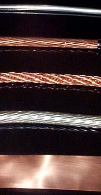
24 Ground Conductor Considerations Sizing - Sufficient to withstand maximum fault current for the maximum clearing time. Inductance - Flat strap conductors have less inductance than their similarly sized round conductor counterparts. Strength/Durability - Round conductors whether solid or stranded are much stronger than a 24 or 26 gauge flat strap conductor. This should be a consideration when backfilling trenches. Exothermic Connections - The preferred type of connection for underground uses. Availability as well as ease of connection is better for the round conductors than the flat strap conductors. Cost Effectiveness - Although the inductance may be less for the flat strap conductors, their cost is much higher. It may be more cost effective to use multiple round conductors, thus lowering overall ground system impedance than single flat strap conductors.
25 Effect of Lead Inductance For 1 meter of conductor, Typically R=0.005 Ohm L=1.5µH V=L di + IR dt For typical strike Imax = 30,000 A in 1µsec V = (1.5 x 10⁻⁶ ) (30,000) + (30,000 x 0.005) (1 x 10⁻⁶ ) V = 45, Volts/meter of conductor Inductive Term Greatly Dominates Resistive Term R L Conductor Model
26 Ground Electrodes Electrodes must be of proper material and cross section to provide a low impedance path to fault current without fusing. Many Types of Electrodes are Available Driven Ground Rods Pole Butt Plates (Distribution Poles) Ground Plates Counterpoise Wires Foundations (UFER GROUNDS) Electrolytic (Enhanced) Ground Rods
27 Ground Electrode Considerations Soil Restivity - Some soils, (such as sandy soils), have such high resistivities that conventional ground rods or ground electrode systems may be unable to attain the desired ground resistance requirement. Enhanced ground electrodes or ground enhancement materials may be required to meet the grounding specification. Soil PH/type - PH a factor in choosing. Some ground rod types work better in different soils. Soil Characteristics - Some sites may have only a few inches of soil (or none) sitting on top of bedrock. In this case, ground mesh is the preferred electrode. (Never drill into bedrock).
28 Electrode Considerations Cont.. Ground Rod Diameter - Doubling diameter of ground rod reduces resistance only 10%. Using larger diameter ground rods is mainly a strength issue (ie. In rocky conditions, a larger diameter ground rod might be advantgageous). RESISTANCE, % 120% 100% 80% 60% 40% 20% 0% ROD DIAMETER, INCHES Ground Rod Length - Doubling length theoretically reduces resistance 40%, actual reduction depends on soil resistivities encountered in multilayered soils. Ground Rod Spacing - Approximately twice the length. (in good soil). RESISTANCE, OHMS ½ 1/2 1" ROD DEPTH, FT
 R := ln 4Lr 2 πlr r R = 32 Ω")

29 Ground Rod Spacing ¾ x 10 Rod ρ = 100 Ω m One Ground Rod ( ρ ) R := ln 4Lr 2 πlr r R = 32 Ω Two Ground Rods Spacing = 20 K := n BB = 2 1 BB 1 R := 1 n ρ 2 π Lr ln 4 Lr r R = 17.4 Ω 1 + ρ π S K ( )

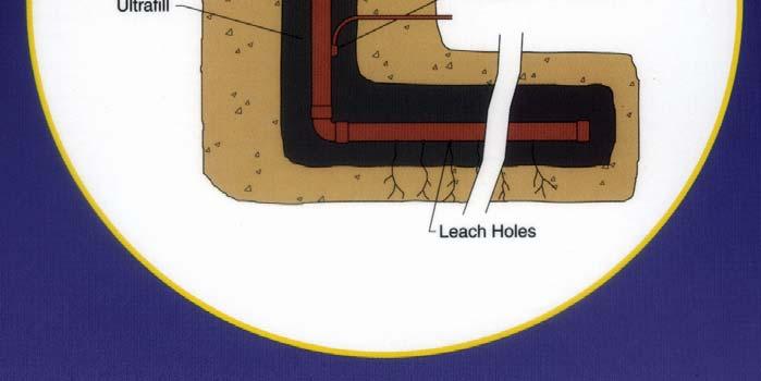
30 Special Electrodes Ufer Grounds - Concrete encased electrode. For example, tying into the tower footing rebar or building pad rebar provides a Ufer ground. Ufer grounds should never be used as the sole ground electrode. Copper Ground Mesh - Used to augment the grounding system. The mesh can be strategically placed to protect personnel against step and touch potentials.

31 Enhanced Grounding Material Should be > 95% pure carbon Should not contain concrete or bentonite fillers


32 Applications Vertical Application Horizontal Application


33 Enhanced Ground Rods Contains electrolytic salts that lower ground resistivity over time


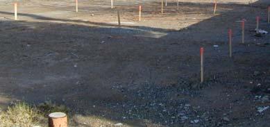
34 Galvanized Ground Rod NFPA - NEGRP Pawnee Site 5/8 x 10 after 10 years in the ground


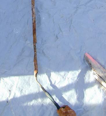
35 Copper Clad Steel Ground Rod NFPA - NEGRP Pawnee Site 5/8 x 8 after 10 years in the ground
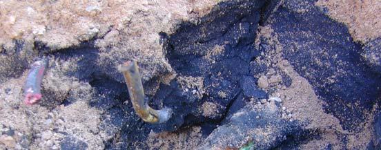


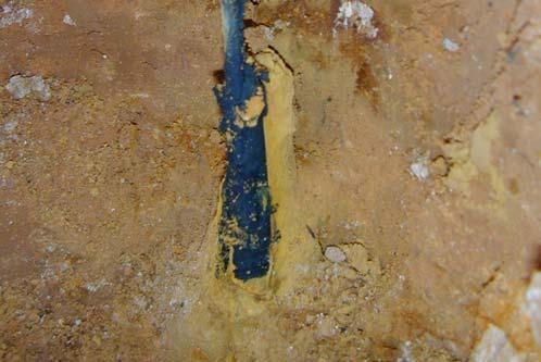
36 Horizontal Cu-Clad Steel Ground Rod in GEM NFPA - NEGRP Pawnee Site Rod corroded away at Cadweld connection 8 of top of rod gone 10 years in the ground
37 II. Bonding i. What is Bonding Definition: (NEC 250) The permanent joining of metallic parts to form an electrically conductive path that will assure electrical continuity and the capacity to conduct safely any current likely to be imposed.
38 ii. Why Bond? No or Poor bonding is often the principle cause of many hazardous and noise- producing situations. Leading to: Unacceptable Voltage Drops Heat Generation Intermittent Operation Electrical Noise High Resistance Grounds Bonding provides near zero voltage difference during ground potential rise
39 iii. How to Bond Interconnect ALL Ground Electrode Systems Electrical Grounding System Lightning Grounding System Telecommunications Grounding System Cable Grounding System Connect all conductive objects together both internal and external to the facility


40 Connectors Connections must be of proper material and mass, and be able to resist corrosion to maintain original low resistance for the life of the system. Types Exothermic Mechanical Compression


41 Ultraweld What is an exothermic reaction? An exothermic reaction is a chemical reaction that liberates heat (thermal energy). The molten copper melts the objects being connected together forming the molecular bond.

42 Exothermic Connections Provides a Molecular Bond Ampacity exceeds that of conductors Connections will not loosen Connections never increase in resistance Does not deteriorate with age Maintenance free
43 Mechanical Connections Used when compression or exothermic connections are not practical/feasible Surface preparation essential Tighten to 75 Inch Pounds Example - Lug to Ground Bar


44 Mechanical Connections 1 2 Surface Preparation Antioxidant Applied 3 Mechanical Connection


45 Compression Connections More reliable than mechanical, less effective than exothermic (Not recommended for underground use) Examples - conductor to compression lug, C-taps


46 Connection Process 2 Crimp Minimum Make sure end of conductor remains at end of barrel; Make first crimp then repeat crimping process


47 Bonding Products Used Ground Bars Equipment Ground Plates Fence and Gate Jumpers Equipotential Mesh and Mats Signal Reference Grids Coaxial Ground Kits

48 III. Total Systems Approach Lightning Protection Surge Suppression Bonding Grounding
49 Why a Systems Approach? These subsystems are not independent. Lightning and Electrical Transient Protection Systems rely on a good grounding & proper bonding for effective performance. Grounding & Bonding, Surge and Lightning Protection are not always well understood in their application in industry. Improper Grounding & Bonding are commonly the root cause of Power Quality Problems.
50 Risks of Not Providing Protecting Human safety Equipment damage Downtime and loss of operations Customer dissatisfaction about reliability Loss of revenue and service


51 IV. Soils Resistivity & Ground Testing
52 How do we create an effective ground electrode system (GES)? What type of facility? Residence, Cellular Tower, Hospital What is the application? Power system, lightning protection, ESD, etc What are the ohmic requirements of the GES? <25 Ω,, <5 Ω, <1 Ω How much area is available? What are the soil conditions? Dry, wet, sandy, rocky, etc.
53 Resistivities of Different Soils
54 Soil Conditions Soil Resistivity Must Be Carefully Considered, Including Moisture Content and Temperature.


55 Soil Resistivity: Wenner Method Soil Resistivity ρ E = 2*π * a * R E
56 Ground Electrode Testing 62% Method (IEEE Std 81) C = Current Probe P = Potential Probe X = Electrode under test Uses Ohms Law to Determine Resistance: R = E/I Resistance = Voltage/Current
57 Probe Spacing P too close to X = False low P too close to C = False high C too close to X = inaccurate reading
58 Site Testing 1. Determine size of ground grid system and calculate length of test leads required. (Pythagorean theorem). Lead Length Critical. 2. Starting at 50, record readings every 50 to obtain a ground resistance curve 3. The point where curve flattens out is the system s ground resistance. (62%)
59 Test Format Distance in Feet Readings in Ohms, Easterly Direction Readings in Ohms, Northerly Direction East Direction North Direction

60 Clamp - On Ground Tester Check ground resistance without auxiliary stakes Resistance without disconnecting from other grounds Ideal for multigrounded systems Rapid continuity check Ground rod or leakage current measurements
61 Clamp-On Method Can be used on both single grounding electrode and multi-bonded/multi bonded/multi- grounding electrode systems. Can only be used on sites supplied by commercial power. Will not work in the case of a 3-phase 3 delta ungrounded system.
62 Clamp-On Method There cannot be any current on the neutral wire, (Less than 5 amps), or the results will be unreliable Proper location of the clamp-on meter is mandatory

63 Clamp-on Ground Tester

64 Clamp-on Ground Tester
65 V. Grounding & Bonding Applications I. Lightning Protection I. What is Lightning? Damaged Caused.. II. What is Lightning Protection? III. Risks of Direct/Indirect Strikes IV. Basic Components II. III. Computer Room Installations I. Ground Subsystems II. Sources of Transients III. Signal Reference Grids Telecomm Installations I. Premise Wiring II. Central Office III. Wireless

66 What is Lightning? Consider Lightning a Gigantic Electrical Spark traveling between Cloud to Cloud or Cloud to Earth containing an average Charge of 30 to 50 Million Volts and a Current of 30,000 Amps.
67 Lightning Characteristics Lightning - High frequency (approx. 1 megahertz) electrical discharge carrying on average 18,000 amps and 30 million volts. Time duration of event is measured in microseconds. Lightning Conductors - Multiple, parallel low impedance paths sufficient enough to carry lightning currents safely to ground terminal system. (IE Master labeled lightning protection system or structural steel). Minimum standard requirements set by UL96A & NFPA 780. * Due to its high frequency & voltage, lightning does not like to stay on one conductor. Therefore, multiple parallel paths are critical!!!
68 Electricity Characteristics Electricity - low frequency (60 Hz) low voltage (<600) and low amperage (<2000). Time duration of an electrical fault is approximately 1 second, possibly longer. (Electrical) Ground Conductor - Sufficient enough in size to provide a safe path for fault currents. Sizing set forth by NEC. Properly size, one conductor is enough. In fact parallel paths are against NEC code.


69 In other words A lightning ground does not equal a green wire ground!!!!!


70 What is Lightning Protection? NFPA 780 A Complete System of Air Terminals, Conductors, Ground Terminals, Interconnecting Conductors, Surge Suppression Devices, and other Connectors or Fittings required to complete the System. UL96A - Installation Standard Master Label Independent Third Party Testing UL96 - Manufacturing Standard
71 Lightning Damage Can Be Traced To: Inadequate direct strike protection Incorrect grounding which allows lightning to flow near sensitive electronics Insufficient transient protection & filtering of power lines Lack of protection on telephone, data and signaling circuits
72 Basic Principles of Lightning Protection Intercept the Lightning Discharge Safely Conduct the Lightning Currents Minimize the Effects of Lightning Currents Dissipate the Lightning Currents in the Earth

73 NFPA 780 Lightning Protection Standard Scope - This document shall cover traditional lightning protection system installation requirements for ordinary structures, misc. structures, special occupancies, etc.

74 Risks Posed from a Direct Strike

75 Risks Posed from an Indirect Strike


76 Basic LP Components Air Terminals Lightning Conductors Ground Terminals Connectors/Fittings Surge Suppression Devices


77 II. Computer Room Installations Grounding System Four Distinct Subsystems NEC Compliant Fault/Personnel Protection Power System Ground (including surge suppression) Lightning Protection subsystem (per NFPA 780) Telecom, data transmission, and signaling circuit surge protection grounding subsystem. Signal Reference Structure
78 Sources of Transient Over-voltages voltages Lightning Induced Surges Power Systems Operations Power System Faults Reactive Load Switching Harmonics Earth Potential Rise Nuclear Electromagnetic Pulse & Solar Flares
79 Transients May be Induced onto: Power Lines Telephone Lines Data Signaling Lines RF Feeders Building Structural Members (lightning) Differential Grounds


80 SIGNAL REFERENCE GRID (SRG) Function: Minimize voltage differences between interconnected equipment by providing a low impedance equipotential ground plane for high frequency low voltage noise. Function:

81 SIGNAL REFERENCE GRID (SRG) SRG Bonded to Building Steel PDU Processors Low Impedance Riser Pedestal Bond Prefabricated SRG


82 III. Telecom Installations
83 Telecom Bonding The sensitivity of the electronic equipment requires that the telecomm cabling and power be effectively equalized to prevent loops or transients that can damage the equipment. To ensure effective equalization, the telecomm ground should be directly attached to the electrical service ground
84 Premise Wiring Applications Applicable Codes/Standards NEC 70 Articles 250, 800 & 830 ANSI J-STDJ STD-607-A
85 NEC Article 800 Communications Circuits Scope - Covers telephone, telegraph (except radio),etc, and telephone systems not connected to a central station system but using similar types of equipment, methods of installation, and maintenance.
86 NEC Article 830 Network Powered Broadband Communications Systems Scope - Covers network-powered broadband communications systems that provide any combination of voice, audio, video, data, and interactive services through a network interface unit.
87 ANSI J-STD-607-A This standards specifies the requirements for a uniform telecommunications grounding and bonding infrastructure that shall be followed within commercial buildings where telecommunications equipment will be installed.
88 Main Elements of Telecomm Grounding and Bonding Structures Telecomm Bonding Conductor Telecomm Main Grounding Busbar (TMGB) Telecomm Bonding Backbone (TBB) Telecomm Grounding Busbar (TGB) Grounding Equalizer, (Formerly TBBIC)

89 Telecommunications Grounding Infrastructure
90 Telecomm Bonding Conductor (Bond to Electrical Service Ground)

91 Telecomm Main Grounding Busbar (TMGB)
92 Telecommunications Bonding Backbone (TBB) Is a conductor that connects all Telecomm Grounding Busbars with the Telecomm Main Ground Busbar. Equalize potential differences between the telecomm system to which it is bonded

93 Telecomm Grounding Busbar (TGB)
94 Grounding Equalizer Conductor that connects elements of the telecommunications grounding infrastructure. (Formerly TBBIBC). Interconnects multiple TGB s s on the top floor and every 3 rd floor in between

95 Conductor Sizing Applies to TBB, GE & TBC
96 Summary For over the past hour, we have presented a tremendous amount of information concerning grounding and bonding, hopefully some of it was informative. If there are other issues you would like addressed, please contact us.

97 Thank You
Attendee Announcements
 Attendee Announcements Seminar Raffle Be sure to drop your raffle ticket in the drum at today s Keynote located in the Mile High Ballroom. You have a chance to win a $250 American Express Gift Card. One
Industrial and Commercial Power Systems Topic 7 EARTHING
 The University of New South Wales School of Electrical Engineering and Telecommunications Industrial and Commercial Power Systems Topic 7 EARTHING 1 INTRODUCTION Advantages of earthing (grounding): Limitation
Outdoor Installation 2: Lightning Protection and Grounding
 Outdoor Installation 2: Lightning Protection and Grounding Training materials for wireless trainers This one hour talk covers lightning protection, grounding techniques and problems, and electrolytic incompatibility.
CONTINUING EDUC ATION
 3 CONTINUING EDUC ATION FOR WISCONSIN ELECTRICIANS 2017 NEC Article 250 2 Hours WISCONSIN CONTRACTORS INSTITUTE N16 W23217 Stone Ridge Drive Suite 290 Waukesha, WI 53188 262-409-4282 www.wcitraining.com
High Voltage Pylon earth Measurements. Tycom (Pty) Ltd Frank Barnes Comtest (Pty) Ltd Presented by Gavin van Rooy
 Ltd Frank Barnes Comtest (Pty) Ltd Presented by Gavin van Rooy") High Voltage Pylon earth Measurements Tycom (Pty) Ltd Frank Barnes Comtest (Pty) Ltd Presented by Gavin van Rooy Abstract The earth connection of high voltage electrical power line pylons is obviously
High Voltage Pylon earth Measurements Tycom (Pty) Ltd Frank Barnes Comtest (Pty) Ltd Presented by Gavin van Rooy Abstract The earth connection of high voltage electrical power line pylons is obviously
Overview of Grounding for Industrial and Commercial Power Systems Presented By Robert Schuerger, P.E.
 Overview of Grounding for Industrial and Commercial Power Systems Presented By Robert Schuerger, P.E. HP Critical Facility Services delivered by EYP MCF What is VOLTAGE? Difference of Electric Potential
Article 250 Grounding & Bonding
 Article 250 Grounding & Bonding AMERICAN ELECTRICAL INSTITUTE N16 W23217 Stone Ridge Dr. Waukesha, WI 53188 855-780-5046 www.aeitraining.com DISCLAIMER NOTE: This course is APPROVED for continuing education
EPG. by Chris C. Kleronomos
 April 1994 EFFECTIVE EQUIPMENT GROUNDING ECOS Electronics Corporation by Chris C. Kleronomos The quality of the electrical wiring and grounding in a facility containing sensitive electronic equipment is
High Voltage Pylon Earth Measurements
 High Voltage Pylon Earth Measurements Speaker: Gavin van Rooy Authors: Frank Barnes and Gavin van Rooy Tycom (Pty) Ltd PO Box 3546, Randburg, 2125, South Africa E-mail: frank@tycom.co.za Phone: 011 787
2/15/2015. Current will always try to return to its source. In order for there to be current, there must be a complete circuit
 Current will always try to return to its source In order for there to be current, there must be a complete circuit Current will take as many paths or circuits available to it to return to the source The
Safety Issues Caused by High Earth Resistance and Identifying Them Using Instruments
 Safety Issues Caused by High Earth Resistance and Identifying Them Using Instruments Thomas Szollossy Senior Technical Support Engineer Power Quality Thailand PQSynergy 2017, Chiang Mai, Thailand Introduction
American Electrical Institute
 American Electrical Institute Oregon Electricians Continuing Education Grounding & Bonding (Article 250) 4 Hours American Electrical Institute PO Box 31131 Spokane, WA 99223 www.aeitraining.com Article
Grounding for Power Quality
 Presents Grounding for Power Quality Grounding for Power Quality NEC 250.53 states that ground resistance should be less than 25 ohms. Is this true? Grounding for Power Quality No! NEC 250.53 states
Wisconsin Contractors Institute Continuing Education
 IMPORTANT NOTE: You should have received an email from us with a link and password to take your final exam online. Please check your email for this link. Be sure to check your spam folder as well. If you
CHAPTER 15 GROUNDING REQUIREMENTS FOR ELECTRICAL EQUIPMENT
 CHAPTER 15 GROUNDING REQUIREMENTS FOR ELECTRICAL EQUIPMENT A. General In a hazardous location grounding of an electrical power system and bonding of enclosures of circuits and electrical equipment in the
SDCS-03 DISTRIBUTION NETWORK GROUNDING CONSTRUCTION STANDARD (PART-I) UNDERGROUND NETWORK GROUNDING. Rev. 01
 UNDERGROUND NETWORK GROUNDING. Rev. 01") SDCS-03 DISTRIBUTION NETWORK GROUNDING CONSTRUCTION STANDARD (PART-I) UNDERGROUND NETWORK GROUNDING Rev. 01 This specification is property of SEC and subject to change or modification without any notice
SDCS-03 DISTRIBUTION NETWORK GROUNDING CONSTRUCTION STANDARD (PART-I) UNDERGROUND NETWORK GROUNDING Rev. 01 This specification is property of SEC and subject to change or modification without any notice
UNDERSTANDING. Ground Resistance Testing. Soil Resistivity. Ground Resistance. 3-Point Measurements. 4-Point Measurements. Clamp-On Measurements
 UNDERSTANDING Ground Resistance Testing Current supply E Ammeter (I) I Voltmeter (E) Ground electrode under test X Auxiliary potential electrode Y Auxiliary current electrode Z R Rx R1 R2 Rn-1 Rn EARTH
GROUNDING. What is it? Al Lewey K7ABL. Disclaimer
 GROUNDING What is it? Al Lewey K7ABL Disclaimer Disclamier Mechanical Engineer with some electrical background My primary reference is References UP THE TOWER The Complete Guide to Tower Construction By
RADIO AND TELEVISION SATELLITE EQUIPMENT
 ARTICLE 810 RADIO AND TELEVISION SATELLITE EQUIPMENT Introduction to Article 810 Radio and Television Satellite Equipment This article covers transmitter and receiver (antenna) equipment and the wiring
Earth Grounding Resistance
 Earth Grounding Resistance Principles, testing methods and applications DIAGSE intermittent electrical problems AVOID unnecessary downtime LEARN earth ground safety principles Why ground, why test? Why
Grounding and Lightning arrestors
 CHAPTER - Four Grounding and Lightning arrestors 4.1. Introduction Electrical connection of neutral point of a supply system or the non current carrying part of electrical equipments to the general mass
White Paper Security Cameras, CATV, GPS and Satellite Protection
 White Paper Security Cameras, CATV, GPS and Satellite Protection 1485-042 White Paper Security Cameras, CATV, GPS and Satellite Protection Security Cameras, CATV, GPS & Satellite Protection Outdoor Closed
Stake-less earth / ground testing
 APPLICATION NOTE Stake-less earth / ground testing NEW DET14C and DET24C CLAMPS GETTING-AROUND ANY CHALLENGE What is stake-less testing? How does it work? Where and how can it be used? What are the potential
SDCS-03 DISTRIBUTION NETWORK GROUNDING CONSTRUCTION STANDARD (PART-II) OVERHEAD NETWORK GROUNDING. Rev. 01
 OVERHEAD NETWORK GROUNDING. Rev. 01") SEC DISTRIBUTION GROUNDING STANDARD SDCS-03 Part-II Rev.01 SDCS-03 DISTRIBUTION NETWORK GROUNDING CONSTRUCTION STANDARD (PART-II) OVERHEAD NETWORK GROUNDING Rev. 01 This specification is property of SEC
SEC DISTRIBUTION GROUNDING STANDARD SDCS-03 Part-II Rev.01 SDCS-03 DISTRIBUTION NETWORK GROUNDING CONSTRUCTION STANDARD (PART-II) OVERHEAD NETWORK GROUNDING Rev. 01 This specification is property of SEC
LIGHTNING EARTHING SYSTEM : A PRACTICAL GUIDE
 International Lightning Protection Association 1 st Symposium Valencia Spain 24th 25th of November, 2011 LIGHTNING EARTHING SYSTEM : A PRACTICAL GUIDE Alain Rousseau SEFTIM (France) ABSTRACT To make a
Need for grounding Codes and Standards for grounding Wind Turbine Generator grounding design Foundation + Horizontal Electrode grounding design
 IEEE PES Transmission and Distribution Conference 2008 Panel Session Large Wind Plant Collector Design Wind Farm Collector System Grounding by Steven W. Saylors, P.E. Chief Electrical Engineer Vestas Americas
Grounding and Bonding
 Grounding and Bonding 2017 Communications Academy Joe Blaschka Jr., PE Grounding/Bonding What is it? Why do we do it? What does the National Electrical Code say? What about fixed locations? What about
Safety earthing. Sector Energy PTI NC. Copyright Siemens AG All rights reserved. Theodor Connor
 Safety earthing Sector Energy PTI NC Theodor Connor Copyright Siemens AG 2008. All rights reserved. Content Introduction Theoretical background Soil Analysis Design of earthing system Measurements on earthing
National Radio Astronomy Observatory Socorro, NM EVLA Memorandum 41 Lightning Protection for Fiber Optic Cable. T. Baldwin June 05, 2002
 National Radio Astronomy Observatory Socorro, NM 87801 EVLA Memorandum 41 Lightning Protection for Fiber Optic Cable T. Baldwin June 05, 2002 Summary Double-armor triple-sheath fiber optic cable will be
SDCS-03 DISTRIBUTION NETWORK GROUNDING CONSTRUCTION STANDARD GROUNDING RESISTANCE MEASUREMENTS AND IMPROVEMENT
 SEC DISTRIBUTION GROUNDING STANDARD SDCS-03 DISTRIBUTION NETWORK GROUNDING CONSTRUCTION STANDARD (PART-III) REV-01 GROUNDING RESISTANCE MEASUREMENTS AND IMPROVEMENT This specification is property of SEC
Earthing of Electrical Devices and Safety
 Earthing of Electrical Devices and Safety JOŽE PIHLER Faculty of Electrical Engineering and Computer Sciences University of Maribor Smetanova 17, 2000 Maribor SLOVENIA joze.pihler@um.si Abstract: - This
MECKLENBURG COUNTY. Land Use and Environmental Service Agency Code Enforcement 2/9/11 ELECTRICAL CONSISTENCY MEETING. Code Consistency Questions
 MECKLENBURG COUNTY Land Use and Environmental Service Agency Code Enforcement 2/9/11 ELECTRICAL CONSISTENCY MEETING Code Consistency Questions 1. I have a 500 KVA generator, with no overcurrent protection
Field Instruction. Induced voltages can occur in overhead lines, underground cables, or in switchyards.
 8.3 Induced Voltage Purpose The purpose of this instruction is to provide awareness of Electrostatic and Electromagnetic induced voltages and the method required to reduce or eliminate it. An induced voltage
SPECIAL SPECIFICATION LIGHTNING PROTECTION SYSTEM
 2004 Specifications CSJ 3622-01-001, ETC. SPECIAL SPECIFICATION 8398 LIGHTNING PROTECTION SYSTEM 1. Description. This Special Specification governs the design and installation of Lightning Protection System
Grounding Recommendations for On Site Power Systems
 Grounding Recommendations for On Site Power Systems Revised: February 23, 2017 2017 Cummins All Rights Reserved Course Objectives Participants will be able to: Explain grounding best practices and code
Chapter 1. Applied Grounding and Bonding. Applied Grounding and Bonding 9/18/2011. Introduction. Introduction. Paul Dobrowsky Member NEC Panel 5
 Applied Grounding and Bonding Paul Dobrowsky Member NEC Panel 5 1 Introduction This presentation is a representative sample from the following Chapters of Applied Grounding and Bonding. Chapter 1, Introduction
Tower Grounding Training For Telecommunications Networks
 Tower Grounding Training For Telecommunications Networks Contact us Today for a FREE quotation to deliver this course at your company?s location. https://www.electricityforum.com/onsite-training-rfq The
GOOD GROUNDING PRACTICES. A Brief Introduction to the Basics of Electrical Grounding for Power Systems
 GOOD GROUNDING PRACTICES A Brief Introduction to the Basics of Electrical Grounding for Power Systems Introduction to Grounding TABLE OF CONTENTS 1.0 Introduction to Grounding 2.0 Standard Industrial Grounding
GROUNDED ELECTRICAL POWER DISTRIBUTION. Excerpt from Inverter Charger Series Manual BY: VIJAY SHARMA ENGINEER
 GROUNDED ELECTRICAL POWER DISTRIBUTION Excerpt from Inverter Charger Series Manual BY: VIJAY SHARMA ENGINEER .0 Conductors for Electrical Power Distribution For single-phase transmission of AC power or
UNDERSTANDING. Ground Resistance Testing. I Voltmeter (E) Grounding. electrode. under test. Ground rod and clamp
 Grounding. electrode. under test. Ground rod and clamp") UNDERSTANDING Ground Resistance Testing Current supply E Ammeter (I) I Voltmeter (E) Grounding electrode under test X Auxiliary potential electrode Y Auxiliary current electrode Z R Rx R1 R2 Rn-1 Rn EARTH
UNDERSTANDING Ground Resistance Testing Current supply E Ammeter (I) I Voltmeter (E) Grounding electrode under test X Auxiliary potential electrode Y Auxiliary current electrode Z R Rx R1 R2 Rn-1 Rn EARTH
Minimizing Lightning and Static Discharge in Broadcasting
 Minimizing Lightning and Static Discharge in Broadcasting Lightning and static discharge represent two of the most damaging and unpredictable events faced by broadcasters. Together or separately they are
6B.6 Substation Grounding
 1 No v 1 6 1 No v 1 6 Iu d a Mo r a r a n d ma n a g e r R a c h e le Ha n n o n Vo l.6 -S u b s ta tio n a n d Hig h Vo lta g e E q u ip me n t;p a r tb -S u b s ta tio n Co n fig u r a tio n s 1. Scope
Lightning Strikes. Presented to the Greater Norwalk Amateur Radio Corporation Inc. February 8, 2017 Steven M. Simons W1SMS
 Lightning Strikes Presented to the Greater Norwalk Amateur Radio Corporation Inc. February 8, 2017 Steven M. Simons W1SMS ARRL CT State Technical Coordinator The Power of Lightning What is a Ground? Design
The Variable Threshold Neutral Isolator (VTNI)
") The Variable Threshold Isolator (VTNI) Installation Instructions INTRODUCTION The is designed specifically for installation between the primary neutral of a power utility distribution system and the secondary
The Variable Threshold Isolator (VTNI) Installation Instructions INTRODUCTION The is designed specifically for installation between the primary neutral of a power utility distribution system and the secondary
Control Cable installation: Best Practice
 Control Cable installation: Best Practice Years of experience has taught Irri-Gator Product s technical personnel that it is virtually impossible to predict an installation s sensitivity to surges (whether
Grounding Essentials for the Shack
 Grounding Essentials for the Shack Lightning Protection AC Power Safety RF Grounding (RF feedback - Tx) RF Noise (RFI - Rcvr) 2014/2015 * What is Lightning? 30-50 million volts 18,000 Amps Xenon lights
Single Earthed Neutral and Multi Earthed Neutral. Single Earthed Neutral and Multi Earthed Neutral: Multi Grounded Neutral System (MEN):
:") Single Earthed Neutral and Multi Earthed Neutral. SEPTEMBER 6, 2011 5 COMMENTS Single Earthed Neutral and Multi Earthed Neutral: In Distribution System Three Phase load is unbalance and non linear so The
Single Earthed Neutral and Multi Earthed Neutral. SEPTEMBER 6, 2011 5 COMMENTS Single Earthed Neutral and Multi Earthed Neutral: In Distribution System Three Phase load is unbalance and non linear so The
Surge Protection and Grounding Issues
 Surge Protection and Grounding Issues Presented to SCTE Chicago Chapter January 21, 2004 By: Nisar Chaudhry VP Electrical Engineering, CTO Introduction Transients caused by disturbances on the power lines
Status Date Prepared Reviewed Endorsed Approved
 Discipline Engineering Standard NSW Category Electrical Title Reference Number PDS 05 (RIC Standard: EP 12 10 00 11 SP) Document Control Status Date Prepared Reviewed Endorsed Approved Mar 05 Standards
GROUND TESTERS For all of your Ground Testing needs...
 GROUND TESTERS For all of your Ground Testing needs... An array of Ground Testers to choose from Whether you are doing a simplified 2-Point, a more complete 3- or 4-Point Fall-of-Potential test, a soil
Stray Voltage and Swimming Pools
 Stray Voltage and Swimming Pools Marty L. Page, P.E. Southern Company malpage@southernco.com October 19 th 2009 2009 Jodie Lane National Conference for Stray Voltage Detection, Mitigation & Prevention
Agenda. Earthing of Telecom Installations using Single Point Earthing. Reference Documents. How many earths? Earthing Issue...
 Earthing of Telecom Installations using Single Point Earthing R. Saji Kumar DGM (IT) O/o The Chief General Manager Trivandrum Agenda Reference Documents Earthing Issue & the Problems Earthing Principle
Importance of Grounding in Power System. Presented by Mr. H Jayakumar Ex- Joint Director CPRI
 Importance of Grounding in Power System Presented by Mr. H Jayakumar Ex- Joint Director CPRI OBJECT OF EARTHING Prime Object of Earthing is to Provide a Zero Potential Surface in and around and under the
Understand the importance of Ground Resistance Testing & much more! (800) (508)
 (508)") Soil Resistivity Ground Resistance 3-Point Measurements 4-Point Measurements Clamp-On Measurements Understand the importance of Ground Resistance Testing & much more! (800) 343-1391 (508) 698-2115 www.aemc.com
Soil Resistivity Ground Resistance 3-Point Measurements 4-Point Measurements Clamp-On Measurements Understand the importance of Ground Resistance Testing & much more! (800) 343-1391 (508) 698-2115 www.aemc.com
Table of Contents. 1 Introduction. 2 System-Level Electrostatic Discharge (ESD) and Electrical Fast Transient (EFT) 3 Electromagnetic Interference
 and Electrical Fast Transient (EFT) 3 Electromagnetic Interference") Electromagnetic Compatibility and Electrical Safety GR-1089-CORE Table of Contents Table of Contents 1 Introduction 1.1 Purpose and Scope.................................. 1 1 1.2 Items Not Covered in
Electromagnetic Compatibility and Electrical Safety GR-1089-CORE Table of Contents Table of Contents 1 Introduction 1.1 Purpose and Scope.................................. 1 1 1.2 Items Not Covered in
Current Probes. User Manual
 Current Probes User Manual ETS-Lindgren Inc. reserves the right to make changes to any product described herein in order to improve function, design, or for any other reason. Nothing contained herein shall
Best Practices for Power and Transient Protection on Rosemount Radar Transmitters
 Technical Note Rosemount Radar Transmitters Best Practices for Power and Transient Protection on Rosemount Radar Transmitters BACKGROUND INTRODUCTION This document describes best practices for power and
Mesh Bonded vs Isolated Bonded Earthing Network for Indoor Grounding
 Mesh Bonded vs Isolated Bonded Earthing Network for Indoor Grounding Rohit Narayan Global Telecom, ERICO PENTAIR Melbourne, Australia Rohit.narayan@pentair.com Mesh Bonded vs Isolated Bonded Earthing Network
K e e l i n g C o m p a n y
 e e l i n g C o m p a n y GOLF IRRIGATION WIRE Page 87 GOLF IRRIGATION WIRE e e l i n g C o m p a n y Page 88 e e l i n g C o m p a n y It is the responsibility of the installer to connect all electronic
Grounding Complications
 Grounding Complications Sensitive Equipment Isolated grounding Supplemental grounds Sensitive Electronic Equipment NEC 647 [2002-2005] Originally intended for audio studios -- now Industrial/commercial
Lightning Protection. Wisconsin Broadcasters Association Broadcasters Clinic. 14 th October 2009 Jeff Welton Regional Sales Manager, Central U.S.
 Lightning Protection Wisconsin Broadcasters Association Broadcasters Clinic 14 th October 2009 Jeff Welton Regional Sales Manager, Central U.S. Nautel Limited 2009 This presentation has been produced for
EMC Philosophy applied to Design the Grounding Systems for Gas Insulation Switchgear (GIS) Indoor Substation
 Indoor Substation") EMC Philosophy applied to Design the Grounding Systems for Gas Insulation Switchgear (GIS) Indoor Substation Marcos Telló Department of Electrical Engineering Pontifical Catholic University of Rio Grande
EMC Philosophy applied to Design the Grounding Systems for Gas Insulation Switchgear (GIS) Indoor Substation Marcos Telló Department of Electrical Engineering Pontifical Catholic University of Rio Grande
The Lightning Event. White Paper
 The Lightning Event White Paper The Lightning Event Surge Protection Solutions for PTC 1 The Lightning Event There are volumes of information available on what we believe lightning is and how we think
SAFETY AND HEALTH STANDARD ELECTRICAL GROUNDING Effective Date: 07/17/10 Standard: Document Number: KUCSH0039 Rev: 4
 SAFETY AND HEALTH STANDARD ELECTRICAL GROUNDING Effective Date: 07/17/10 Standard: 16.10 Document Number: KUCSH0039 Rev: 4 16.10.1 INTRODUCTION 16.10.1.1 The intent of this standard is to ensure that continuity
Equipment Rack Grounding. Technical Note
 Equipment Rack Grounding Technical Note Equipment Rack Grounding Surge Protection Solutions for PTC 1 Equipment Rack Grounding Equipment racks and cabinets can provide an unwanted path for lightning surge
ECE 528 Understanding Power Quality
 ECE 528 Understanding Power Quality http://www.ece.uidaho.edu/ee/power/ece528/ Paul Ortmann portmann@uidaho.edu 208-316-1520 (voice) 1 Today Wiring and grounding Why it s important References Terms and
Electrical Wiring: Commercial, Seventh Canadian Edition
 Electrical Wiring Commercial Canadian 7th Edition Mullin SOLUTIONS MANUAL Full download at: https://testbankreal.com/download/electrical-wiring-commercialcanadian-7th-edition-mullin-solutions-manual/ Unit
PRACTICAL PROBLEMS WITH SUBSTATION EARTHING
 1 PRACTICAL PROBLEMS WITH SUBSTATION EARTHING Dr Hendri Geldenhuys Craig Clark Eskom Distribution Technology This paper considers the issues around substation sites where the soil resistivity is of particularly
Continued from Part 1 Rules 1 25.
 Continued from Part 1 Rules 1 25. 26 225.32 Disconnect Location The disconnecting means for a building or structure must be installed at a readily accessible location, either outside the building or structure
FTTH ENGINEERING AND INSTALLATION INTRODUCTION
 1 FTTH ENGINEERING AND INSTALLATION INTRODUCTION GROUNDING FTTH SYSTEMS AT THE HOME. By Dean Mischke, P.E., V.P. Grounding and bonding. Why are we worried about such an old school concept in the modern
Grounding and Bonding of Service Equipment
 Grounding and Bonding of Service Equipment 1. Grounding means: attached to an earth ground. 2. Bonding means: physically connected to insure electrical continuity. NEC 250.4 1. Grounding: Electrical Systems
Device Interconnection
 Device Interconnection An important, if less than glamorous, aspect of audio signal handling is the connection of one device to another. Of course, a primary concern is the matching of signal levels and
Education & Training
 Distribution System Operator Certificate This program provides you with a proficient working knowledge in modern electric power distribution systems. These four classes are designed to walk students through
7P Series - Surge Protection Device (SPD) Features 7P P P
 Features 7P P P") Features 7P.09.1.255.0100 7P.01.8.260.1025 7P.02.8.260.1025 SPD Type 1+2 Surge arrester range - single phase system / three phase system Surge arresters suitable in low-voltage applications in order to
Features 7P.09.1.255.0100 7P.01.8.260.1025 7P.02.8.260.1025 SPD Type 1+2 Surge arrester range - single phase system / three phase system Surge arresters suitable in low-voltage applications in order to
FAQ ON EARTHING STANDARDS 16/08/2018
 FAQ ON EARTHING STANDARDS 16/08/2018 This document has been updated to include changes made to substation earthing layouts that have been made necessary due to copper theft. The main changes to be aware
AC Voltage- Pipeline Safety and Corrosion MEA 2015
 AC Voltage- Pipeline Safety and Corrosion MEA 2015 WHAT ARE THE CONCERNS ASSOCIATED WITH AC VOLTAGES ON PIPELINES? AC concerns Induced AC Faults Lightning Capacitive coupling Safety Code Induced AC Corrosion
Understanding Ground Resistance Testing
 Understanding Ground Resistance Testing CURRENT SUPPLY E I AMMETER (I) VOLTMETER (E) X AUXILIARY POTENTIAL ELECTRODE Y AUXILIARY CURRENT ELECTRODE Z Rx R1 R2 Rn-1 Rn Ground Rod and Clamp Resistance in
Tower and Station Grounding
 Tower and Station Grounding Southwest Dallas County Amateur Radio Club 1/17/2017 Presented By Maurice Martin KM5RF Why Ground? What You Don't Want! During lightning, the surrounding air is immediately
Section 6: System Grounding Bill Brown, P.E., Square D Engineering Services
 Section 6: System Grounding Bill Brown, P.E., Square D Engineering Services Introduction The topic of system grounding is extremely important, as it affects the susceptibility of the system to voltage
The Isolator/Surge Protector (ISP)
") The Isolator/Surge Protector (ISP) Technical Literature INTRODUCTION The Isolator/Surge Protector (ISP) is a solid-state device with logic-controlled circuitry which simultaneously provides DC isolation
The Isolator/Surge Protector (ISP) Technical Literature INTRODUCTION The Isolator/Surge Protector (ISP) is a solid-state device with logic-controlled circuitry which simultaneously provides DC isolation
The Isolator/Surge Protector (ISP)
") The Isolator/Surge Protector (ISP) Technical Literature INTRODUCTION The Isolator/Surge Protector (ISP) is a solid-state device with logic-controlled circuitry which simultaneously provides isolation and
The Isolator/Surge Protector (ISP) Technical Literature INTRODUCTION The Isolator/Surge Protector (ISP) is a solid-state device with logic-controlled circuitry which simultaneously provides isolation and
EARTH GROUNDING RESISTANCE
 ART GROUNDING RITANC Principles, testing methods and applications DIAG intermittent electrical problems AVOID unnecessary downtime LARN earth ground safety principles Why ground, why test? Why ground?
TD1016: An overview of Lightning Protection for Ham Radio Stations.
 TD1016: An overview of Lightning Protection for Ham Radio Stations. PolyPhaser 2225 Park Place Minden, NV 89423, USA TF: 800.325.7170 T: +1.775.782.2511 F: +1.775.782.2551 www.polyphaser.com TD1016: An
DEVAR Inc. 706 Bostwick Ave., Bridgeport CT Tel , Fax
 DEVAR Inc. 706 Bostwick Ave., Bridgeport CT 06605 Tel 203 368 6751, Fax 203 368 3747 http://www.devarinc.com, e-mail: info@devarinc.com INSTRUCTION MANUAL PLUG & SEND TRANSMITTER MODEL PS-1-B PS-1-B Rev
Options to Improve the MEN System into the 21 st Century
 Options to Improve the MEN System into the 21 st Century Chris Halliday Electrical Consulting and Training Pty Ltd, Gladstone NSW, Australia. Email: chris@elect.com.au Web: www.elect.com.au Abstract Network
EVALUATION OF THE EARTH RESISTANCE VALUE FOR ESE LIGHTNING ARRESTOR TECHNIQUE FOR THE SOLAR PLANTS IN INDIA
 EVALUATION OF THE EARTH RESISTANCE VALUE FOR ESE LIGHTNING ARRESTOR TECHNIQUE FOR THE SOLAR PLANTS IN INDIA Rajat Verma Project Engineer BHEL EDN, BANGALURU, MYSORE ROAD, KARNATAKA 560024, India ABSTRACT
6. Internal lightning protection
 6. Internal lightning protection 6.1 Equipotential bonding for metal installations Equipotential bonding according to IEC 60364-4- 41 and IEC 60364-5-54 Equipotential bonding is required for all newly
60Hz Ratings. Typical Applications. Features & Characteristics. Ratings
 The PCR is a solid-state device designed to simultaneously provide DC isolation and AC continuity/grounding when used with cathodically protected structures, such as pipelines, tanks, grounding systems,
Jake Leahy s Electrical Code Connection. A look at Grounding and Bonding of Electrical Services Article Florida Building Code 5 th Edition
 Jake Leahy s Electrical Code Connection A look at Grounding and Bonding of Electrical Services Article 250 2014 Florida Building Code 5 th Edition Wiring Integrity. Completed wiring installations shall
METAL GROUNDING AND BONDING
 METAL GROUNDING AND BONDING Hubbell's full line of grounding and bonding products will protect and secure active equipment from harmful electrical interference. These products provide the best performance
UNITED STATES OF DEPARTMENT OF AGRICULTURE Rural Utilities Service BULLETIN 1751F-815. Electrical Protection of Outside Plant
 UNITED STATES OF DEPARTMENT OF AGRICULTURE Rural Utilities Service BULLETIN 1751F-815 SUBJECT: TO: Electrical Protection of Outside Plant All Telecommunications Borrowers RUS Telecommunications Staff EFFECTIVE
Standard Recommended Practice. Mitigation of Alternating Current and Lightning Effects on Metallic Structures and Corrosion Control Systems
 NACE Standard RP0177-2000 Item No. 21021 Standard Recommended Practice Mitigation of Alternating Current and Lightning Effects on Metallic Structures and Corrosion Control Systems This NACE International
Stray Electricity. Occurs as small voltage differences between
 Stray Electricity Occurs as small voltage differences between structure and the floor structure and installed equipment floor and equipment or through liquids Voltage difference - current will flow Generally
Contents. 1 Introduction. 2 System-Level Electrostatic Discharge (ESD) and Electrical Fast Transient. 3 Electromagnetic Interference
 and Electrical Fast Transient. 3 Electromagnetic Interference") Issue 3, October 2002 Electromagnetic Compatibility and Electrical Safety Contents Telcordia GR-1089 - Documentation Information Generic Requirements Notice Of Disclaimer................. iii Contents.......................................
Issue 3, October 2002 Electromagnetic Compatibility and Electrical Safety Contents Telcordia GR-1089 - Documentation Information Generic Requirements Notice Of Disclaimer................. iii Contents.......................................
UNIVERSITY OF MISSOURI Liquid-Filled Utility Transformers 2016 Q1
 GENERAL: The scope of this document is to provide instruction for the installation and testing of Medium Voltage, 3 Phase, Pad Mounted Transformers installed at the University of Missouri. Preferred transformers
Telephone Cable Locating Techniques
 Chapter 2 Telephone Cable Locating Techniques Introduction Read Chapter One of this manual to learn more general information about each of the following signal application methods. The following paragraphs
Overvoltage Protection
 Overvoltage Protection S T U D E N T M A N U A L March 31, 2005 2 STUDENT TRAINING MANUAL Prerequisites: Single-Phase Transformer Load Checks Objectives: From memory, you will be able to describe the electrical
Instruction Manual for Digital Grounding Resistance Meter
 Instruction Manual for Digital Grounding Resistance Meter Instruction Manual for Digital Grounding Resistance Meter Table of Contents I. Overview...2 II. Open-case Inspection...3 III. Safety Precautions...4
IP Transport Communications for Power Stations and Other High-Reliability Locations- Challenges and Protection
 IP Transport Communications for Power Stations and Other High-Reliability Locations- Challenges and Protection Presented by: John Fuller Principal Network Design Engineer AT&T Technology Planning and Engineering
Tech Talk (12) Down to Earth: A Discussion of the General Requirements for the Earthing of Control and Instrumentation Systems
 Down to Earth: A Discussion of the General Requirements for the Earthing of Control and Instrumentation Systems") 701880MAC0010.1177/0020294017701880 research-article2017 Contributed Paper Tech Talk (12) Down to Earth: A Discussion of the General Requirements for the Earthing of Control and Instrumentation Systems
701880MAC0010.1177/0020294017701880 research-article2017 Contributed Paper Tech Talk (12) Down to Earth: A Discussion of the General Requirements for the Earthing of Control and Instrumentation Systems