High Voltage Pylon earth Measurements. Tycom (Pty) Ltd Frank Barnes Comtest (Pty) Ltd Presented by Gavin van Rooy
|
|
|
- Mervin Bryan
- 5 years ago
- Views:
Transcription


1 High Voltage Pylon earth Measurements Tycom (Pty) Ltd Frank Barnes Comtest (Pty) Ltd Presented by Gavin van Rooy

2 Abstract The earth connection of high voltage electrical power line pylons is obviously very important. The different design of pylons can change the earth bond task drastically. This paper will give feedback from an actual experiment conducted with a new design Pylon in South Africa and discusses the difficulty of getting repeatable measurements and knowing that the Pylon is properly earthed.
3 Introduction Electric-power transmission is the bulk transfer of electrical energy, from generating power plants to electrical substations located near demand centres. This is distinct from the local wiring between high-voltage substations and customers, which is typically referred to as electric power distribution. Transmission lines, when interconnected with each other, become transmission networks.
4 Why Ground? Poor grounding not only contributes to unnecessary downtime, but a lack of good grounding is also dangerous and increases the risk of equipment failure. Without an effective grounding system, we could be exposed to the risk of electric shock, not to mention instrumentation errors, harmonic distortion issues, power factor problems and a host of possible intermittent dilemmas. If fault currents have no path to the ground through a properly designed and maintained grounding system, they will find unintended paths that could include people.
5 Why Test grounding systems Over time, corrosive soils with high moisture content, high salt content, and high temperatures can degrade ground rods and their connections. So although the ground system when initially installed, had low earth ground resistance values, the resistance of the grounding system can increase if the ground rods are eaten away. That is why it is highly recommended that all grounds and ground connections are checked at least annually as a part of your normal Predictive Maintenance plan. During these periodic checks, if an increase in resistance of more than 20 % is measured, the technician should investigate the source of the problem, and make the correction to lower the resistance
6 What is a good ground? There is a good deal of confusion as to what constitutes a good ground and what the ground resistance value needs to be. Ideally a ground should be of zero ohms resistance.
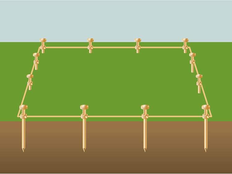
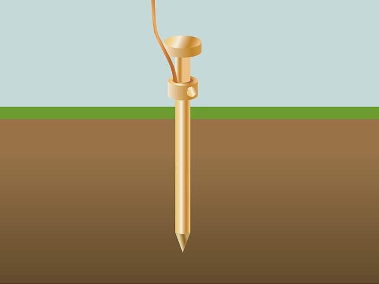
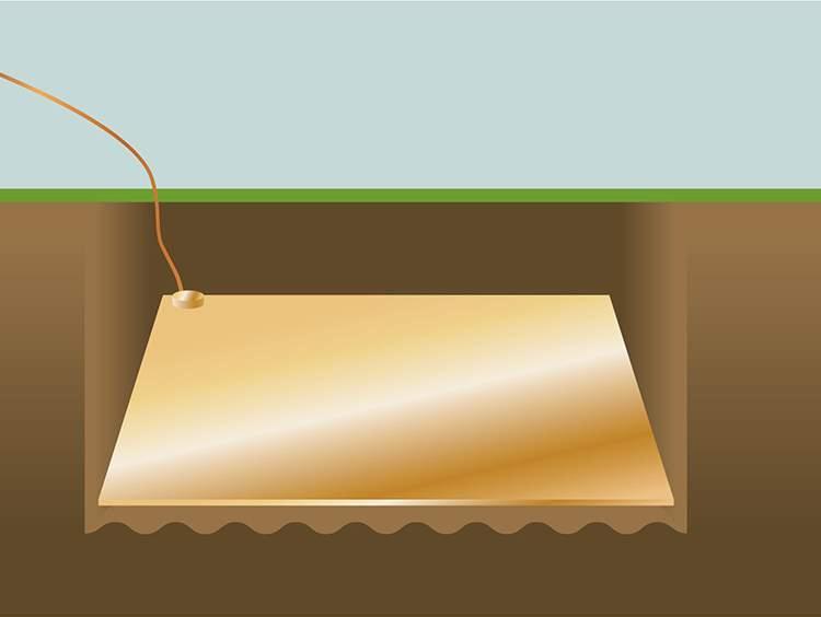
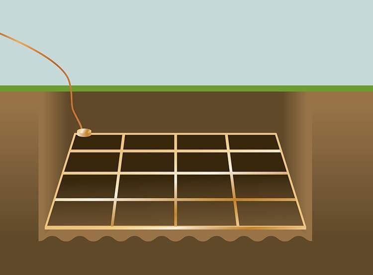
7 What is Earthing? Simple definition of an earth is to connect the electric circuit/equipment to the earth s conductive surface. The reason first and foremost is for personal safety and protection of equipment in case of fault currents and lightning strikes. In studies done by power quality experts, they will relate that poor grounding/earthing is second only to improper wiring as the leading cause of equipment malfunction. There are various methods and systems to do this, starting with simple stakes driven into the ground to multiple grounds rod s, mesh or grids systems.
8 Earthing
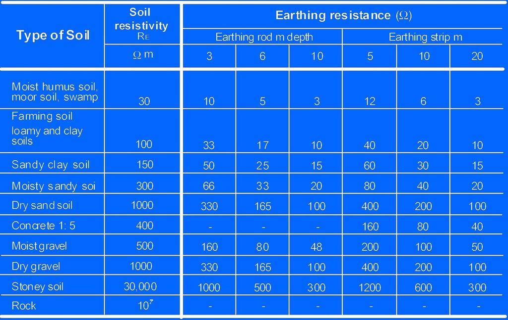
9 Earthing One of the systems is then chosen taking into consideration of the type of installation. For example a substation, electrical pylon and anything in between. Another consideration would be the soil resistivity which is dependent on may factors i.e. Sandy/semi desert and rocky areas, which would be much less conductive(1000 ohms per meter) than say loamy and clay soil(100 ohms per meter). These factors are not always constant and can be affected by the climate, rainfall and temperature. Changes in the site can also result in the soils resistivity changing- paving, development.

10 Earthing Lightning strikes on equipment with poorly maintained protection systems destroy millions of Rands of equipment and equate to lost production every year. Using Earthing/ground testing in a PDM protocol will help prevent possible dangerous situations and loss of downtime (= money)
11 Soil Resistivity Soil resistivity measurements have a threefold purpose 1. The data is used to make a subsurface geophysical survey of the area- identify ore location, depth to bedrock and any geological phenomena. 2. Soil resistivity has a direct impact on the degree of corrosion on underground pipes or any metallic structure. A decrease in resistivity relates to an increase in corrosion activity. 3. The resistivity directly affects the design of the grounding system.
12 Soil Resistivity Here are some factors that we should take into account which will have an effect on the measurements taken. First of these is the physical dimensions & depth of a typical earth electrode assuming all connections to the electrode are in perfect condition and present a very low resistance. This is because the earth is made up of various layers and not all have the same constant resistivity, it follows that the deeper the electrode is driven into the earth the better the resistance will be. If the electrode length is doubled the resistance level can be reduced by 40%. The diameter of the rod/spike does not have a big influence
13 Soil Resistivity

14 Soil resistivity Second is the sphere of influence. When using multiple earth electrodes it does not necessary follow that the more electrodes used the lower the resistance will be.
15 Soil Resistivity & Sphere of influence Definition of a ground electrode is a conductor or group of conductors in intimate contact with the earth for the purpose of providing a connection with the soil. This definition does not refer to an actual ohm resistance value of the electrode. The resistance is determined by the resistivity of soil which the electrode or earthing systems are in contact with. When an object is grounded it is then forced to assume the same potential as the earth. If the potential of the grounded object is higher or lower, current will pass through the grounding connection until the potential of the object and earth are the same. The earth electrode is that connection path.
16 Sphere of Influence The effect of the concentric shell is that it takes a finite amount of earth for the ground rod to fully realise its resistance value. This finite amount of earth is known as the ground rod s sphere of influence. The sphere of influence of a ground rod is commonly thought to be a radius around the ground rod equal to its length; the ground rod achieves approximately 94% of its resistance value at this radius. (100% is achieved at approximately 2.5 times the rod length). Hence, grounding is necessary to maintain an object s potential equal to that of the earth s.
17 Sphere of influence The volume formula is: V=(5 x x L cubed)/3 We can simplify this by rounding PI down to 3 to cancel the 3 below the line. This will leave us with: V=5 x L cubed Using this formula we can calculate that a single 10 foot driven rod would utilize 5000 cubic feet. An 8 foot rod would only utilize 2560 cubic feet. Thus for additional electrodes to be effective they must be spaced so that their spheres of influence do not intersect. The minimum distance is roughly the depth of the electrode for the second electrode to be effective.

18 Ground potential Rise In the case of extremely large fault currents induced into the ground by a phase to earth fault, or by lightning. The ground can not immediately reduce the potential to zero. This condition is called Ground Potential Rise. In these conditions not only will the grounding system rise in electrical potential but will radiate into the soil from the centre of the grounding point.
19 Ground potential rise This phenomenon is demonstrated by cows in field after a lightning strike, not all of the cows are affected, some are killed and some close by are unaffected. This is because the potential differences radiates outwards from the point of the strike. The cows facing the strike are more likely to be killed as the potential difference between the front and rear legs and across the animal s heart is greater than the cows standing with their sides towards the strike- their potential difference between the two front legs is much lower.
20 Ground Potential rise Step potential Voltage between the feet of a person standing near an energised grounded object. Equal to the difference in voltage, given by the voltage distribution curve and a point some distance away. Should you be standing in a storm close to a pylon best you stand on one foot- side on to the pylon. The lowest potential difference would be from you left small toe to your big toe in theory.

21 Ground potential Rise Touch Potential For example, a crane that was not grounded because it was on rubber tyres and that contacted an energized line would expose any person in contact with any metallic part of the crane. The full fault current would then pass directly through that person to ground.
22 Measuring earth Resistance Earth resistance is measured in ohms per meter or ohms per centimetre and represents the resistance of a cubic meter of earth. There are a number of methods of measuring soil resistivity of which the Wenner is most popular. Wenner simplified formula: Rho = 2 x PI x A x R Where Rho is the average soil resistivity at depth A PI is A is the distance between the electrodes in cm R is the measured resistance value in ohms.
23 Measuring Earth resistance Using the Wenner 4-pole method the depth of the electrodes is typically 6 inches, the distance between the electrodes is also the depth at which the earth resistivity is calculated(a). As results as sometimes distorted by geological anomalies and spurious induced currents, Various readings should be take to form a profile. Instruments nowadays compensate for harmonics, currents using automatic frequency control.

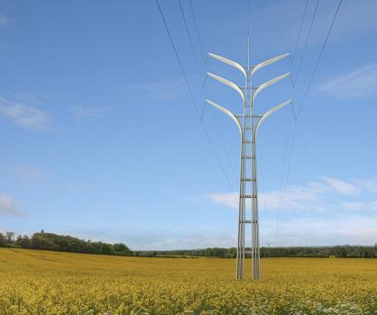
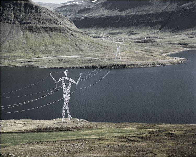
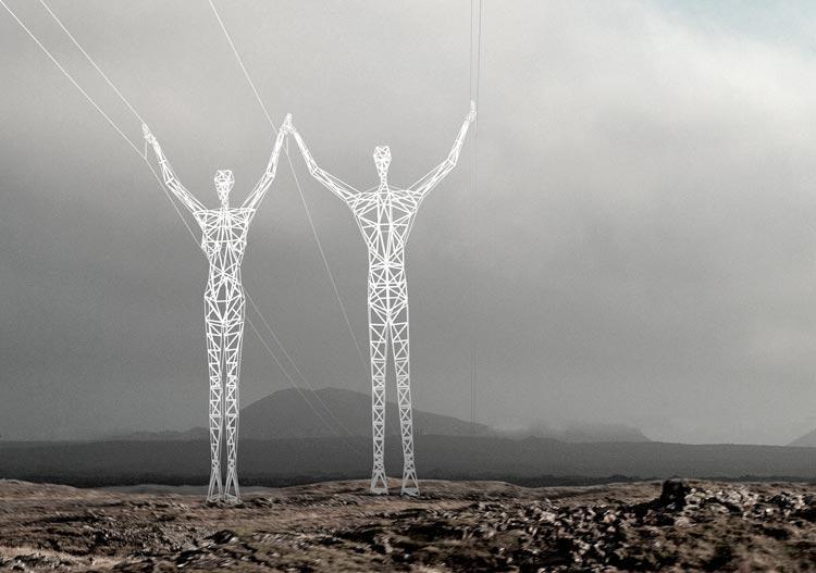
24 Transmission Towers 765KV & 400KV transmission lines- One operational with overhead earth connected. 765KV - Guyed unconnected new tower. One centre point with four guy ropes. Earth connections cast in concrete. No removable earth straps. Reason why there is not a removable earth straps it that the rebar is connected to the stub on which the tower is constructed. Overhead earth connections Using the fall of potential method when measuring the earth resistance on one pylon foot, all the earthing points together including the adjacent pylons will be measured.
25 Transmission Towers Counterpoise Earth When an acceptable connection cannot be achieved a Counterpoise earth is used. This provides a high capacitance and therefore a relatively low impendence path to earth. The reduction in Impedence will reduce insulator flash over due to lightning strikes. The energy from the lightning strike travels down the counterpoise and is reflected at the terminal end. The counterpoise will act as a series resistance with a distributed leakage to ground. A counterpoise would be in excess of a grounding electrode system, not in lieu of.

26 Transmission Towers Fall of Potential Method This method requires that the earth under test must be disconnected from the system and other earthing points. In this case of a 765KV pylon, if it were possible, this would be a dangerous exercise substantial currents may exist in the earth conductor.

27 Transmission Towers Selective Method Up and until the 1990 s the established method for measuring earth resistance was the fall of potential method. With the Selective method the major significance of this would be that pylon testing can now be carried out on each individually foot separately, without disconnecting any other earthing points.
28 Transmission towers Selective Earth Method Two earth stakes are placed in the soil in a direct line away from the earth stake of interest. Spacing of 20 metres is usually sufficient. A know current is generated between the outer stake and earth stake, while the drop in voltage potential is measure between inner and earth stake. Only the current flowing through the earth stake of interest is of interest and is measured with the clamp and then calculates the resistance. By this method we can measure the earth resistance of any foot of the pylon without disconnecting any other earth parts.
29 Beaufort West Two separate pylons were measured- one Guyed tower and one Four base tower. One with the overhead earth disconnected. Both with rebar earthing system. Five measurements taken on the Guyed tower. Terrain semi desert with sandy soil. The setup of the stakes was as follows- 60m and 100m form the measuring point. Resistance of both pylons was found to be similar and very low (3.4Ω). Multiple measurements were done in various directions and results were similar.
30 References Fluke: earth ground Resistance LEM: earth grounding principles AEMC: Understanding soil resistivity testing Lightning Engineers: earth Ground Systems-Testing & Importance The Internet: About Electrical Grounding Wikipedia

31 Thank you
High Voltage Pylon Earth Measurements
 High Voltage Pylon Earth Measurements Speaker: Gavin van Rooy Authors: Frank Barnes and Gavin van Rooy Tycom (Pty) Ltd PO Box 3546, Randburg, 2125, South Africa E-mail: frank@tycom.co.za Phone: 011 787
Earth Grounding Resistance
 Earth Grounding Resistance Principles, testing methods and applications DIAGSE intermittent electrical problems AVOID unnecessary downtime LEARN earth ground safety principles Why ground, why test? Why
Understanding Soil Resistivity Testing
 Technical Hotline: (0) -9 Technical Hotline: (0) -9 www.aemc.com www.aemc.com Understanding Testing Effects of on Ground Electrode Resistance Factors Affecting APPLICATION NOTES OCTOBER Understanding Testing
EARTH GROUNDING RESISTANCE
 ART GROUNDING RITANC Principles, testing methods and applications DIAG intermittent electrical problems AVOID unnecessary downtime LARN earth ground safety principles Why ground, why test? Why ground?
Industrial and Commercial Power Systems Topic 7 EARTHING
 The University of New South Wales School of Electrical Engineering and Telecommunications Industrial and Commercial Power Systems Topic 7 EARTHING 1 INTRODUCTION Advantages of earthing (grounding): Limitation
Grounding and Lightning arrestors
 CHAPTER - Four Grounding and Lightning arrestors 4.1. Introduction Electrical connection of neutral point of a supply system or the non current carrying part of electrical equipments to the general mass
PERFORMANCE ASSESSMENT OF SUBSTATION SITE EARTHING USING FLUKE 1625 GROUND TESTER
 Nigerian Journal of Technology (NIJOTECH) Vol. 32, No. 1, March, 2013, pp. 49 53. Copyright 2013 Faculty of Engineering, University of Nigeria. ISSN 1115-8443 PERFORMANCE ASSESSMENT OF SUBSTATION SITE
Safety Issues Caused by High Earth Resistance and Identifying Them Using Instruments
 Safety Issues Caused by High Earth Resistance and Identifying Them Using Instruments Thomas Szollossy Senior Technical Support Engineer Power Quality Thailand PQSynergy 2017, Chiang Mai, Thailand Introduction
Field Instruction. Induced voltages can occur in overhead lines, underground cables, or in switchyards.
 8.3 Induced Voltage Purpose The purpose of this instruction is to provide awareness of Electrostatic and Electromagnetic induced voltages and the method required to reduce or eliminate it. An induced voltage
GROUNDED ELECTRICAL POWER DISTRIBUTION. Excerpt from Inverter Charger Series Manual BY: VIJAY SHARMA ENGINEER
 GROUNDED ELECTRICAL POWER DISTRIBUTION Excerpt from Inverter Charger Series Manual BY: VIJAY SHARMA ENGINEER .0 Conductors for Electrical Power Distribution For single-phase transmission of AC power or
Attendee Announcements
 Attendee Announcements Seminar Raffle Be sure to drop your raffle ticket in the drum at today s Keynote located in the Mile High Ballroom. You have a chance to win a $250 American Express Gift Card. One
UNDERSTANDING. Ground Resistance Testing. Soil Resistivity. Ground Resistance. 3-Point Measurements. 4-Point Measurements. Clamp-On Measurements
 UNDERSTANDING Ground Resistance Testing Current supply E Ammeter (I) I Voltmeter (E) Ground electrode under test X Auxiliary potential electrode Y Auxiliary current electrode Z R Rx R1 R2 Rn-1 Rn EARTH
Earthing of Electrical Devices and Safety
 Earthing of Electrical Devices and Safety JOŽE PIHLER Faculty of Electrical Engineering and Computer Sciences University of Maribor Smetanova 17, 2000 Maribor SLOVENIA joze.pihler@um.si Abstract: - This
Outdoor Installation 2: Lightning Protection and Grounding
 Outdoor Installation 2: Lightning Protection and Grounding Training materials for wireless trainers This one hour talk covers lightning protection, grounding techniques and problems, and electrolytic incompatibility.
Overvoltage Protection
 Overvoltage Protection S T U D E N T M A N U A L March 31, 2005 2 STUDENT TRAINING MANUAL Prerequisites: Single-Phase Transformer Load Checks Objectives: From memory, you will be able to describe the electrical
EPG. by Chris C. Kleronomos
 April 1994 EFFECTIVE EQUIPMENT GROUNDING ECOS Electronics Corporation by Chris C. Kleronomos The quality of the electrical wiring and grounding in a facility containing sensitive electronic equipment is
SDCS-03 DISTRIBUTION NETWORK GROUNDING CONSTRUCTION STANDARD (PART-II) OVERHEAD NETWORK GROUNDING. Rev. 01
 OVERHEAD NETWORK GROUNDING. Rev. 01") SEC DISTRIBUTION GROUNDING STANDARD SDCS-03 Part-II Rev.01 SDCS-03 DISTRIBUTION NETWORK GROUNDING CONSTRUCTION STANDARD (PART-II) OVERHEAD NETWORK GROUNDING Rev. 01 This specification is property of SEC
SEC DISTRIBUTION GROUNDING STANDARD SDCS-03 Part-II Rev.01 SDCS-03 DISTRIBUTION NETWORK GROUNDING CONSTRUCTION STANDARD (PART-II) OVERHEAD NETWORK GROUNDING Rev. 01 This specification is property of SEC
HV Substation Earthing Design for Mines
 International Journal of Engineering Research and Development e-issn: 2278-067X, p-issn: 2278-800X, www.ijerd.com Volume 4, Issue 6 (October 2012), PP. 100-107 HV Substation Earthing Design for Mines M.
SDCS-03 DISTRIBUTION NETWORK GROUNDING CONSTRUCTION STANDARD (PART-I) UNDERGROUND NETWORK GROUNDING. Rev. 01
 UNDERGROUND NETWORK GROUNDING. Rev. 01") SDCS-03 DISTRIBUTION NETWORK GROUNDING CONSTRUCTION STANDARD (PART-I) UNDERGROUND NETWORK GROUNDING Rev. 01 This specification is property of SEC and subject to change or modification without any notice
SDCS-03 DISTRIBUTION NETWORK GROUNDING CONSTRUCTION STANDARD (PART-I) UNDERGROUND NETWORK GROUNDING Rev. 01 This specification is property of SEC and subject to change or modification without any notice
Evaluation of Soil Resistivity Characteristics forsubstation Grounding: a Case Study of a University Campus in South-West Zone, Nigeria
 Evaluation of Soil Resistivity Characteristics forsubstation Grounding: a Case Study of a University Campus in South-West Zone, Nigeria Adegboyega Gabriel A Bells University of Technology, Ota, Nigeria
PRACTICAL PROBLEMS WITH SUBSTATION EARTHING
 1 PRACTICAL PROBLEMS WITH SUBSTATION EARTHING Dr Hendri Geldenhuys Craig Clark Eskom Distribution Technology This paper considers the issues around substation sites where the soil resistivity is of particularly
There are a wide variety of ground resistance testers available on the
 Featured Products: Choosing the Right Ground Resistance Tester There are a wide variety of ground resistance testers available on the market today. These vary in design, features, and complexity, and include
GROUND TESTERS For all of your Ground Testing needs...
 GROUND TESTERS For all of your Ground Testing needs... An array of Ground Testers to choose from Whether you are doing a simplified 2-Point, a more complete 3- or 4-Point Fall-of-Potential test, a soil
Cable Protection against Earth Potential Rise due to Lightning on a Nearby Tall Object
 Cable Protection against Earth Potential Rise due to Lightning on a Nearby Tall Object U. S. Gudmundsdottir, C. F. Mieritz Abstract-- When a lightning discharge strikes a tall object, the lightning current
Grounding for Power Quality
 Presents Grounding for Power Quality Grounding for Power Quality NEC 250.53 states that ground resistance should be less than 25 ohms. Is this true? Grounding for Power Quality No! NEC 250.53 states
Asset Protection Cathodic Protection Soil Resistivity Measurement. Work Instruction No.:
 Asset Protection Cathodic Protection Soil Resistivity Measurement Approved by: Manager Pipeline Standards 1 PURPOSE This work instruction describes the processes to be followed when measuring soil resistivity.
Safety earthing. Sector Energy PTI NC. Copyright Siemens AG All rights reserved. Theodor Connor
 Safety earthing Sector Energy PTI NC Theodor Connor Copyright Siemens AG 2008. All rights reserved. Content Introduction Theoretical background Soil Analysis Design of earthing system Measurements on earthing
Stray Voltage and Swimming Pools
 Stray Voltage and Swimming Pools Marty L. Page, P.E. Southern Company malpage@southernco.com October 19 th 2009 2009 Jodie Lane National Conference for Stray Voltage Detection, Mitigation & Prevention
Understanding Ground Resistance Testing
 Understanding Ground Resistance Testing CURRENT SUPPLY E I AMMETER (I) VOLTMETER (E) X AUXILIARY POTENTIAL ELECTRODE Y AUXILIARY CURRENT ELECTRODE Z Rx R1 R2 Rn-1 Rn Ground Rod and Clamp Resistance in
Understand the importance of Ground Resistance Testing & much more! (800) (508)
 (508)") Soil Resistivity Ground Resistance 3-Point Measurements 4-Point Measurements Clamp-On Measurements Understand the importance of Ground Resistance Testing & much more! (800) 343-1391 (508) 698-2115 www.aemc.com
Soil Resistivity Ground Resistance 3-Point Measurements 4-Point Measurements Clamp-On Measurements Understand the importance of Ground Resistance Testing & much more! (800) 343-1391 (508) 698-2115 www.aemc.com
Need for grounding Codes and Standards for grounding Wind Turbine Generator grounding design Foundation + Horizontal Electrode grounding design
 IEEE PES Transmission and Distribution Conference 2008 Panel Session Large Wind Plant Collector Design Wind Farm Collector System Grounding by Steven W. Saylors, P.E. Chief Electrical Engineer Vestas Americas
The Lightning Event. White Paper
 The Lightning Event White Paper The Lightning Event Surge Protection Solutions for PTC 1 The Lightning Event There are volumes of information available on what we believe lightning is and how we think
SAFETY ISSUES RELATED TO THE CONNECTION OF MV AND HV GROUNDING
 SAFETY ISSUES RELATED TO THE CONNECTION OF MV AND HV GROUNDING Y. Rajotte J. Fortin G. Lessard Hydro-Québec, Canada Hydro-Québec, Canada Hydro-Québec, Canada e-mails: rajotte.yves@ireq.ca fortin.jacques@ireq.ca
A Case Study on Selection and Application of Lightning Arrester and Designing its Suitable Grounding Grid
 A Case Study on Selection and Application of Lightning Arrester and Designing its Suitable Grounding Grid 1 Arpan K. Rathod, 2 Chaitanya H. Madhekar Students Electrical Engineering, VJTI, Mumbai, India
Stake-less earth / ground testing
 APPLICATION NOTE Stake-less earth / ground testing NEW DET14C and DET24C CLAMPS GETTING-AROUND ANY CHALLENGE What is stake-less testing? How does it work? Where and how can it be used? What are the potential
Single Earthed Neutral and Multi Earthed Neutral. Single Earthed Neutral and Multi Earthed Neutral: Multi Grounded Neutral System (MEN):
:") Single Earthed Neutral and Multi Earthed Neutral. SEPTEMBER 6, 2011 5 COMMENTS Single Earthed Neutral and Multi Earthed Neutral: In Distribution System Three Phase load is unbalance and non linear so The
Single Earthed Neutral and Multi Earthed Neutral. SEPTEMBER 6, 2011 5 COMMENTS Single Earthed Neutral and Multi Earthed Neutral: In Distribution System Three Phase load is unbalance and non linear so The
AC Voltage- Pipeline Safety and Corrosion MEA 2015
 AC Voltage- Pipeline Safety and Corrosion MEA 2015 WHAT ARE THE CONCERNS ASSOCIATED WITH AC VOLTAGES ON PIPELINES? AC concerns Induced AC Faults Lightning Capacitive coupling Safety Code Induced AC Corrosion
UNDERSTANDING. Ground Resistance Testing. I Voltmeter (E) Grounding. electrode. under test. Ground rod and clamp
 Grounding. electrode. under test. Ground rod and clamp") UNDERSTANDING Ground Resistance Testing Current supply E Ammeter (I) I Voltmeter (E) Grounding electrode under test X Auxiliary potential electrode Y Auxiliary current electrode Z R Rx R1 R2 Rn-1 Rn EARTH
UNDERSTANDING Ground Resistance Testing Current supply E Ammeter (I) I Voltmeter (E) Grounding electrode under test X Auxiliary potential electrode Y Auxiliary current electrode Z R Rx R1 R2 Rn-1 Rn EARTH
Importance of Grounding in Power System. Presented by Mr. H Jayakumar Ex- Joint Director CPRI
 Importance of Grounding in Power System Presented by Mr. H Jayakumar Ex- Joint Director CPRI OBJECT OF EARTHING Prime Object of Earthing is to Provide a Zero Potential Surface in and around and under the
Earth/ground measurement guide
 ARA CO.,LTD. 1694, 1694/1 Prachasongkhro Road, Dindaeng, Dindaeng, Bangkok 10400 Tel. 02-692-3980, Fax. 02-692-3978 -mail: sales@asras.com www.asras.com; www.asras.co.th arth/ground resistance an soil
Harger Lightning & Grounding. *Grounding and Bonding* The Foundation For Effective Electrical Protection
 Harger Lightning & Grounding *Grounding and Bonding* The Foundation For Effective Electrical Protection Objectives 1. Define the difference between grounding & bonding and to describe the roles they play
CONTINUING EDUC ATION
 3 CONTINUING EDUC ATION FOR WISCONSIN ELECTRICIANS 2017 NEC Article 250 2 Hours WISCONSIN CONTRACTORS INSTITUTE N16 W23217 Stone Ridge Drive Suite 290 Waukesha, WI 53188 262-409-4282 www.wcitraining.com
Electricity Supply to Africa and Developing Economies. Challenges and opportunities. Technology solutions and innovations for developing economies
 Electricity Supply to Africa and Developing Economies. Challenges and opportunities. Technology solutions and innovations for developing economies Magnetic induced currents and voltages on earthed lines
Power Cables and their Application
 Power Cables and their Application Parti Materials Construction Criteria for Selection Project Planning Laying and Installation Accessories Measuring and Testing Editor: Lothar Heinhold 3rd revised edition,
Power Quality. Case Study. Conrad Bottu Laborelec January 2008
 Case Study Electromagnetic compatibility (EMC) study Breakdown of low voltage electronic equipment in a 25 kv substation Conrad Bottu Laborelec January 2008 Power Quality Power Quality 1 Introduction Description
American Electrical Institute
 American Electrical Institute Oregon Electricians Continuing Education Grounding & Bonding (Article 250) 4 Hours American Electrical Institute PO Box 31131 Spokane, WA 99223 www.aeitraining.com Article
White Paper Security Cameras, CATV, GPS and Satellite Protection
 White Paper Security Cameras, CATV, GPS and Satellite Protection 1485-042 White Paper Security Cameras, CATV, GPS and Satellite Protection Security Cameras, CATV, GPS & Satellite Protection Outdoor Closed
Appendix. Appendix. Getting Down to Earth. AVO, International NJATC 07
 IBEW NECA Appendix ATTITUDE SKILL KNOWLEDGE FOR APPRENTICESHIP & TRAINING THE ELECTRICAL INDUSTRY Appendix Getting Down to Earth AVO, International Appendix IBEW NECA ATTITUDE SKILL KNOWLEDGE FOR APPRENTICESHIP
Instruction Manual for Digital Grounding Resistance Meter
 Instruction Manual for Digital Grounding Resistance Meter Instruction Manual for Digital Grounding Resistance Meter Table of Contents I. Overview...2 II. Open-case Inspection...3 III. Safety Precautions...4
Analysis of lightning performance of 132KV transmission line by application of surge arresters
 Analysis of lightning performance of 132KV transmission line by application of surge arresters S. Mohajer yami *, A. Shayegani akmal, A.Mohseni, A.Majzoobi High Voltage Institute,Tehran University,Iran
INTEGRATED METHOD IN ELECTROMAGNETIC INTERFERENCE STUDIES
 INTEGRATED METHOD IN ELECTROMAGNETIC INTERFERENCE STUDIES Jinxi Ma and Farid P. Dawalibi Safe Engineering Services & technologies ltd. 1544 Viel, Montreal, Quebec, Canada, H3M 1G4 Tel.: (514) 336-2511
Power System Neutral/Ground Voltages Causes, Safety Concerns and Mitigation
 Power System Neutral/Ground Voltages Causes, Safety Concerns and Mitigation A. P. Sakis Meliopoulos Georgia Institute of Technology September 7, 2004 Tele-Seminar 2004 A. P. Sakis Meliopoulos 1 Power System
Earth/ground measurement guide. Earth/ground resistance and soil resistivity testers
 Earth/ground measurement guide Earth/ground resistance and soil resistivity testers About the Chauvin Arnoux Group Founded in Paris, France in 1893, CHAUVIN ARNOUX has spent the centuries since then developing
Article 250 Grounding & Bonding
 Article 250 Grounding & Bonding AMERICAN ELECTRICAL INSTITUTE N16 W23217 Stone Ridge Dr. Waukesha, WI 53188 855-780-5046 www.aeitraining.com DISCLAIMER NOTE: This course is APPROVED for continuing education
Table of Contents. MFJ-1778 G5RV Multiband Antenna
 Table of Contents MFJ-1778 G5RV Multiband Antenna Introduction... 1 Theory Of Operation... 1 80 meter band:... 1 40 meter band:... 1 30 meter band:... 2 20 meter band:... 2 17 meter band:... 2 15 meter
Options to Improve the MEN System into the 21 st Century
 Options to Improve the MEN System into the 21 st Century Chris Halliday Electrical Consulting and Training Pty Ltd, Gladstone NSW, Australia. Email: chris@elect.com.au Web: www.elect.com.au Abstract Network
APPLICATION OF THE ELECTROMAGNETIC FIELD METHOD TO STUDY A COMMUNICATION SATELLITE SITE DAMAGED BY LIGHTNING
 APPLICATION OF THE ELECTROMAGNETIC FIELD METHOD TO STUDY A COMMUNICATION SATELLITE SITE DAMAGED BY LIGHTNING W. Ruan, R. Southey, F. P. Dawalibi Safe Engineering Services & technologies ltd. 1544 Viel,
GOOD GROUNDING PRACTICES. A Brief Introduction to the Basics of Electrical Grounding for Power Systems
 GOOD GROUNDING PRACTICES A Brief Introduction to the Basics of Electrical Grounding for Power Systems Introduction to Grounding TABLE OF CONTENTS 1.0 Introduction to Grounding 2.0 Standard Industrial Grounding
Device Interconnection
 Device Interconnection An important, if less than glamorous, aspect of audio signal handling is the connection of one device to another. Of course, a primary concern is the matching of signal levels and
Practical Lightning Mitigation
 Practical Lightning Mitigation Jerry Hogan MBA, BSEE Director of Engineering, Solara Technical Sales Jerry Hogan, MBA, BSEE Director of Eng. Solara Technical Sales BSEE, University of Colorado MBA, University
SDCS-03 DISTRIBUTION NETWORK GROUNDING CONSTRUCTION STANDARD GROUNDING RESISTANCE MEASUREMENTS AND IMPROVEMENT
 SEC DISTRIBUTION GROUNDING STANDARD SDCS-03 DISTRIBUTION NETWORK GROUNDING CONSTRUCTION STANDARD (PART-III) REV-01 GROUNDING RESISTANCE MEASUREMENTS AND IMPROVEMENT This specification is property of SEC
ACCURATE SIMULATION OF AC INTERFERENCE CAUSED BY ELECTRICAL POWER LINES: A PARAMETRIC ANALYSIS
 ACCURATE SIMULATION OF AC INTERFERENCE CAUSED BY ELECTRICAL POWER LINES: A PARAMETRIC ANALYSIS J. Liu and F. P. Dawalibi Safe Engineering Services & technologies ltd. 1544 Viel, Montreal, Quebec, Canada
LIGHTNING EARTHING SYSTEM : A PRACTICAL GUIDE
 International Lightning Protection Association 1 st Symposium Valencia Spain 24th 25th of November, 2011 LIGHTNING EARTHING SYSTEM : A PRACTICAL GUIDE Alain Rousseau SEFTIM (France) ABSTRACT To make a
CHAPTER 15 GROUNDING REQUIREMENTS FOR ELECTRICAL EQUIPMENT
 CHAPTER 15 GROUNDING REQUIREMENTS FOR ELECTRICAL EQUIPMENT A. General In a hazardous location grounding of an electrical power system and bonding of enclosures of circuits and electrical equipment in the
SAFETY AND HEALTH STANDARD ELECTRICAL GROUNDING Effective Date: 07/17/10 Standard: Document Number: KUCSH0039 Rev: 4
 SAFETY AND HEALTH STANDARD ELECTRICAL GROUNDING Effective Date: 07/17/10 Standard: 16.10 Document Number: KUCSH0039 Rev: 4 16.10.1 INTRODUCTION 16.10.1.1 The intent of this standard is to ensure that continuity
A New Technology. for Measuring Overhead Line and Cable Impedance Values and the Ground Impedance of Large Substations. Feature
 Feature A New Technology for Measuring Overhead Line and Cable Impedance Values and the Ground Impedance of Large Substations Introduction The knowledge of overhead line and cable impedances is very important
Installation Instructions Hustler 6-BTV Trap Vertical
 Installation Instructions Hustler 6-BTV Trap Vertical ASSEMBLY 1. Check the package contents against the parts list on page 2. 2. WARNING. Installation of this product near power lines is dangerous. For
ABSTRACTS of SESSION 6
 ABSTRACTS of SESSION 6 Paper n 1 Lightning protection of overhead 35 kv lines by antenna-module long flashover arresters Abstract: A long-flashover arrester (LFA) of a new antenna-module type is suggested
GROUND RESISTANCE TESTERS
 GROUND RESISTANCE TESTERS For all of your Ground Integrity Testing needs... An array of Ground Resistance Testers to choose from... Whether you are doing a simplified 2-Point, a more complete - or 4-Point
GROUNDING. What is it? Al Lewey K7ABL. Disclaimer
 GROUNDING What is it? Al Lewey K7ABL Disclaimer Disclamier Mechanical Engineer with some electrical background My primary reference is References UP THE TOWER The Complete Guide to Tower Construction By
Distribution Network Capacitor Resonance A Case Study
 Distribution Network Capacitor Resonance A Case Study Authors: Chris Halliday Frank Iannelli Dr Robert Barr Director of Technical Services Power Quality Technician Director and Training Electrical Consulting
DIGITAL GROUND RESISTANCE TESTERS
 DIGITAL GROUND RESISTANCE TESTERS 3640 4610 X Y Z C1 P2 C2 GROUND RESISTANCE TESTER MODEL 3640 Press To Measure! X-Z Fault Xv-Y Hi Resistance Xv-Y Hi Noise REFER TO USER MANUAL FOR FAULT WARNING LIGHT
National Radio Astronomy Observatory Socorro, NM EVLA Memorandum 41 Lightning Protection for Fiber Optic Cable. T. Baldwin June 05, 2002
 National Radio Astronomy Observatory Socorro, NM 87801 EVLA Memorandum 41 Lightning Protection for Fiber Optic Cable T. Baldwin June 05, 2002 Summary Double-armor triple-sheath fiber optic cable will be
Lightning Strikes. Presented to the Greater Norwalk Amateur Radio Corporation Inc. February 8, 2017 Steven M. Simons W1SMS
 Lightning Strikes Presented to the Greater Norwalk Amateur Radio Corporation Inc. February 8, 2017 Steven M. Simons W1SMS ARRL CT State Technical Coordinator The Power of Lightning What is a Ground? Design
MODERN COMPUTATIONAL METHODS FOR THE DESIGN AND ANALYSIS OF POWER SYSTEM GROUNDING
 MODERN COMPUTATIONAL METHODS FOR THE DESIGN AND ANALYSIS OF POWER SYSTEM GROUNDING J. Ma and F. P. Dawalibi Safe Engineering Services & technologies ltd. 1544 Viel, Montreal, Quebec, Canada, H3M 1G4 Tel.:
Agenda. Earthing of Telecom Installations using Single Point Earthing. Reference Documents. How many earths? Earthing Issue...
 Earthing of Telecom Installations using Single Point Earthing R. Saji Kumar DGM (IT) O/o The Chief General Manager Trivandrum Agenda Reference Documents Earthing Issue & the Problems Earthing Principle
Examples of Design for Cathodic Protection Systems
 Examples of Design for Cathodic Protection Systems CURRENT REQUIREMENTS From Estimated Exposed Surface Area Estimating current requirements from expected exposed surface is always subject to error. There
ABSTRACT 1 INTRODUCTION
 ELECTROMAGNETIC ANALYSIS OF WIND TURBINE GROUNDING SYSTEMS Maria Lorentzou*, Ian Cotton**, Nikos Hatziargyriou*, Nick Jenkins** * National Technical University of Athens, 42 Patission Street, 1682 Athens,
ET 40 - Electrician Theory Examination Marking Schedule
 ET 40 - Electrician Theory Examination Marking Schedule Notes:1. means that the preceding statement/answer earns 1 mark. 2. This schedule sets out the accepted answers to the examination questions. A marker
2kVA EARTH TESTING CURRENT INJECTION SYSTEM 4046 / 4047 DATASHEET REDPHASE INSTRUMENTS
 2kVA EARTH TESTING CURRENT INJECTION SYSTEM 4046 / 4047 DATASHEET REDPHASE INSTRUMENTS Contents Section Brief Description... 1 Where and why it is used... 1.1 Induced Measureable Parameters... 1.2 Hardware
Electrical TP-18 February 2017 ELECTRICAL TECHNICAL PAPER 18 FREQUENTLY ASKED QUESTIONS ABOUT CATHODIC PROTECTION SYSTEM EQUIPMENT TESTING
 ELECTRICAL TECHNICAL PAPER 18 FREQUENTLY ASKED QUESTIONS ABOUT CATHODIC PROTECTION SYSTEM EQUIPMENT TESTING CATHODIC PROTECTION SYSTEM EQUIPMENT TESTING Question No. 1 What should I (the contractor) check
Instruction Manual for Digital Grounding Resistance Meter. Table of Contents
 I. Overview...2 II. Open-case Inspection...3 III. Safety Precautions...4 IV. Work Principle...7 V. Appearance Description...9 VI. Technical Characteristics 10 VII. Resistance Measurement Method..12 VIII.Battery
Grounding and Bonding
 Grounding and Bonding 2017 Communications Academy Joe Blaschka Jr., PE Grounding/Bonding What is it? Why do we do it? What does the National Electrical Code say? What about fixed locations? What about
WHY YOU NEED A CURRENT BALUN
 HF OPERATORS WHY YOU NEED A CURRENT BALUN by John White VA7JW NSARC HF Operators 1 What is a Balun? A BALUN is a device typically inserted at the feed point of a dipole-like antenna wire dipoles, Yagi
AC INTERFERENCE OF TRANSMISSION LINES ON RAILWAYS: INFLUENCE OF TRACK-CONNECTED EQUIPMENT I. ABSTRACT
 AC INTERFERENCE OF TRANSMISSION LINES ON RAILWAYS: INFLUENCE OF TRACK-CONNECTED EQUIPMENT R. D. Southey, J. Liu, F. P. Dawalibi, Y. Li Safe Engineering Services & technologies ltd. 1544 Viel, Montreal,
A PARAMETRIC ANALYSIS OF AC INTERFERENCE CAUSED BY HIGH VOLTAGE POWER LINES ON NEIGHBORING RAILROAD TRACKS
 A PARAMETRIC ANALYSIS OF AC INTERFERENCE CAUSED BY HIGH VOLTAGE POWER LINES ON NEIGHBORING RAILROAD TRACKS Yexu Li and Farid Paul Dawalibi Safe Engineering Services & technologies ltd. 1544 Viel, Montreal,
ENGINEERING REPORT PHASES I & II MITIGATOR PERFORMANCE TESTS
 ENGINEERING REPORT PHASES I & II MITIGATOR PERFORMANCE TESTS INDUCED AC MITIGATION PERFORMANCE ON A STEEL GAS TRANSMISSION PIPELINE REPORT OF JANUARY 29, 2014 Copyright MATCOR, Inc. 2014 MITIGATOR TM VS.
Status Date Prepared Reviewed Endorsed Approved
 Discipline Engineering Standard NSW Category Electrical Title Reference Number PDS 05 (RIC Standard: EP 12 10 00 11 SP) Document Control Status Date Prepared Reviewed Endorsed Approved Mar 05 Standards
The influence of environment on condition of location damage in screen of the coaxial cable. 1. Introduction
 Computer Applications in Electrical Engineering The influence of environment on condition of location damage in screen of the coaxial cable Wiesław Tarczyński Opole University of Technology 45-233 Opole,
SECTION 3 BASIC AUTOMATIC CONTROLS UNIT 12 BASIC ELECTRICITY AND MAGNETISM. Unit Objectives. Unit Objectives 2/29/2012
 SECTION 3 BASIC AUTOMATIC CONTROLS UNIT 12 BASIC ELECTRICITY AND MAGNETISM Unit Objectives Describe the structure of an atom. Identify atoms with a positive charge and atoms with a negative charge. Explain
2/15/2015. Current will always try to return to its source. In order for there to be current, there must be a complete circuit
 Current will always try to return to its source In order for there to be current, there must be a complete circuit Current will take as many paths or circuits available to it to return to the source The
Application Note (Revision NEW) Original Instructions. EMI Control in Electronic Governing Systems
 Original Instructions. EMI Control in Electronic Governing Systems") Application Note 50532 (Revision NEW) Original Instructions EMI Control in Electronic Governing Systems General Precautions Read this entire manual and all other publications pertaining to the work to
Application Note 50532 (Revision NEW) Original Instructions EMI Control in Electronic Governing Systems General Precautions Read this entire manual and all other publications pertaining to the work to
COAXIAL TRANSMISSION LINE COMMON-MODE CURRENT
 COAXIAL TRANSMISSION LINE COMMON-MODE CURRENT Introduction Coaxial transmission lines are popular for their wide frequency bandwidth and high resistance to electromagnetic interference (EMI). Coax cables
Back-flashover Investigation of HV Transmission Lines Using Transient Modeling of the Grounding Systems
 Back-flashover Investigation of HV Transmission Lines Using Transient Modeling of the Grounding Systems F. Amanifard* and N. Ramezani** Abstract: The article presents the transients analysis of the substation
Signs of End of Life FM Antennas and Transmission Line Systems
 Signs of End of Life FM Antennas and Transmission Line Systems Thomas B. Silliman, PE Copyright 2017 Electronics Research, Inc. All rights reserved. Introduction Factors that influence the life of antennas
What Are We Protecting? Over-Voltage Protection for CP Systems. Personnel (primary) Equipment (secondary)
 Equipment (secondary)") What Are We Protecting? Personnel (primary) Equipment (secondary) Over-Voltage Protection for CP Systems Personnel Protection: Touch Potential Personnel Protection: Step Potential Equipment Protection
What Are We Protecting? Personnel (primary) Equipment (secondary) Over-Voltage Protection for CP Systems Personnel Protection: Touch Potential Personnel Protection: Step Potential Equipment Protection
THE EFFECTS OF INCREASED FAULT CURRENT ON THE EXISTING SUBSTATION GROUNDING SYSTEM a Case Study
 THE EFFECTS OF INCREASED FAULT CURRENT ON THE EXISTING SUBSTATION GROUNDING SYSTEM a Case Study Research Project By MOHAU MAPANE 689839 Submitted for the partial fulfilment of the requirements for the
CONTINUOUS COUNTERPOISE ON POLES
 Project Procedure CONTINUOUS COUNTERPOISE ON POLES 07/25/2011 PAGE 1 OF 5 1.0 PURPOSE The purpose of this procedure is to provide guidance and direction for the installation of continuous counterpoise
FALL-OF-POTENTIAL GROUND RESISTANCE TESTER
 FALL-OF-POTENTIAL GROUND RESISTANCE TESTER Models 3620, 3640 & 4610 Call toll free (800) 537-0351 or visit www.allspec.com Measures soil resistivity (4-Point) (Model 4610) Measures ground resistance (2-
Instruction Manual. TT1000 Tower Earth Tester. Rev 01
 Instruction Manual TT1000 Tower Earth Tester Rev 01 Contents 1 Introduction... 3 2 Features... 3 3 Operation... 4 3.1 Test Lead Configuration... 5 3.2 Probe Integrity Test... 6 3.3 Impedance measurement...