Grounding and Bonding of Service Equipment
|
|
|
- Noah Lloyd
- 6 years ago
- Views:
Transcription
1 Grounding and Bonding of Service Equipment 1. Grounding means: attached to an earth ground. 2. Bonding means: physically connected to insure electrical continuity. NEC Grounding: Electrical Systems that are grounded shall be connected to earth in a m anner that w ill lim it the voltage im posed by lightning, line surges, or unintentional contact w ith highervoltage lines and that w ill stabilize the voltage to earth during normal operation. 2. Grounding: Noncurrent carrying conductive m aterials enclosing electrical conductors or equipment, or forming part of such equipment shall be connected to earth so as to limit the voltage to ground on these materials. 3. Bonding: Noncurrent carrying conductive materials enclosing electrical conductors or equipment, or forming part of such equipment, shall be connected together and to the electrical supply source in a manner that establishes an effective groundfault current path. 4. Bonding: Electrical conductive materials that are likely to becom e energized shall be connected together and to the electrical supply in a manner that establishes an effective groundfault path. 5. Effective Path: Electrical equipment and wiring and other electrically conductive material likely to become energized shall be installed in a manner that creates a permanent, lowimpedance circuit capable of safely carrying the maximum groundfault current likely to be im posed on it from any point on the w iring system w here a ground fault may occur to the electrical supply source. The earth shall not be used as the sole equipment grounding conductor or effective groundfault current path. 6. Objectionable Currents: The grounding of electrical systems, circuit conductors, surge arresters, and conductive noncurrent carrying materials and equipment shall be installed and arranged in a m anner that w ill prevent objectionable current over the grounding conductors or grounding paths. 1
2 1. Alterations to stop objectionable current: If the use of multiple grounding connections results in objectionable current, one or m ore of the follow ing alterations shall be perm itted to be m ade, provided that the other requirem ents are m et: A. Discontinue one or more, but not all of such grounding connections B. Change the locations of the grounding connections C. Interrupt the continuity of the conductor or conductive path interconnecting the grounding connections D. Take other suitable remedial and approved action 2. L im itations: The provisions of this section shall not be considered as perm itting equipment from being operated on systems or branch circuits that are not grounded as required by this section. Currents that introduce noise or data error in electronic equipment shall not be considered the objectionable currents addressed in this section. NEC System Grounding Connections: A premise wiring system supplied by a grounded AC service shall have a grounding electrode conductor connected to the grounded service conductor, at each service. 2. General: The connection shall be made at any accessible point from the load end of the service drop or lateral to and including the term inal or bus to w hich the grounded service conductor is connected at the service disconnecting means. 3. Bus: W here the main bonding jumper is a wire or busbar and is installed from the neutral bar or bus to the equipment grounding terminal bar or bus in the service equipment, the grounding electrode conductor shall be permitted to be connected to the equipm ent grounding term inal or bus to w hich the m ain bonding jum per is connected 4. Load Side Grounding Connections: A grounding connection shall not be made to any grounded circuit conductor on the load side of the service disconnecting means. 5. Grounded Conductor Brought to Service Equipment: W here an AC system operating at less than 1000 volts is grounded at any point, the grounded conductor shall be run to each service disconnecting means and shall be bonded to each disconnecting means enclosure. Bonding 1. General: Bonding shall be provided where necessary to ensure electrical continuity and the capacity to conduct safely any fault current likely to be imposed. 2. Bonding of Services: The noncurrent carrying metal parts of equipment shall be effectively bonded together. A. The service raceways, cable trays, cable bus framework, auxiliary gutters or service cable armor or sheath. B. All service enclosures containing service conductors, including meter fittings and boxes interposed in the service raceway or armor. C Any metallic raceway of armor enclosing a grounding electrode conductor. Bonding shall apply at each end and to all intervening raceways, boxes, and enclosures between the service equipment and the grounding electrode. NE Instrument Transformer Circuits: Secondary circuits of current and potential instrument transformers shall be grounded where the primary windings are connected to circuits of 300 volts or more to ground and where on switchboards shall be grounded irrespective of voltage. 2. Instrument Transformer Cases: Cases of frames of instrument transformers shall be grounded where accessible to other than qualified persons. 3. Cases of Instruments, Meters, and Relays operating at less than 1000 volts: Instruments, meters, and relays operating with winding or working parts at less than 1000 volts shall be grounded. 4. Instrument Grounding Conductor: The grounding conductor for secondary circuits of instrument transformers and for instrument cases shall not be smaller than #12 copper or #10 aluminum. Cases of instrument transformers, instruments, meters, and relays that are mounted directly on grounded metal surfaces of enclosures or grounded metal switchboard panels shall be considered to be grounded and no additional grounding conductor shall be required. 2
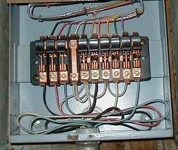
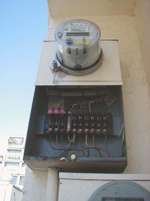
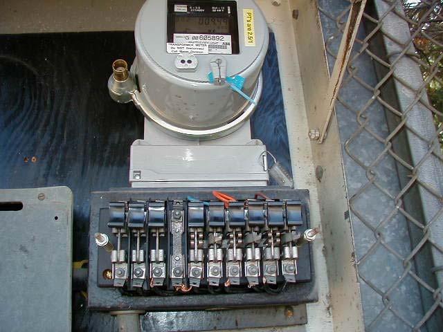
3 Typical Self Contained Installation W 1 L1 L2 W 2 N W 3 MAIN Bonding Jumper Bond Typical CT Installation Grounding and Bonding Points W 1 CT CT L1 L2 W 2 N W 3 W 4 W 5 G L1 L2 N W 6 G W 7 3
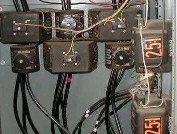
4 W 12 W 5 W 6 CT 1 CT2 CT 3 W 1 W 2 W 3 W 4 W 10 N W 7 W 9 G W 11 W 8 Typical Switchboard Installation 4
5 Ground Loops 6/13/2011 What is the name of the grounded conductor in an electrical circuit? What color is it? What is it s function? 5
6 What is the name of the ground conductor in an electrical circuit? What color is it? What is it s function? A B N G 6
7 A ground loop exists when an electrical system is connected with multiple paths to ground When two or more devices are connected to a common ground through different paths a ground loop occurs A Designed Ground Loop A B N G VM 7
8 A Problem Ground Loop A B N G VM VM Currents flow through these multiple paths and develop voltages that can damage sensitive equipment, cause noise, and affect meter readings which offset from actual values 8
9 They can cause indicating meters to peg up or peg down and/or lock up They can cause sensitive electronic equipment to be inaccurate or even fail NEC defines a ground as a conducting connection between an electrical circuit and earth A ground loop can be defined as objectionable current flowing in that ground or return path 9
10 The simplest ground loop involves a connection between two different earth grounds Panel L1 N G Water Pipe VM Lower Higher VM 10
11 Even though NEC requires grounding electrodes and metal parts to be bonded together, there will still be differences in ground potentials in most systems One common cause of ground loops is double bonding of the grounded conductor NEC requires the neutral to be bonded to ground at only one place, at the source entrance or first disconnect 11
12 When the neutral is double bonded, returning neutral current will split per Kirtchoff's law and flow in the ground circuit This current can cause varying voltage references to equipment in the circuit such as metering Panel L1 N G VM VM 12
13 The addition of another ground compounds the problem Panel L1 N G VM Water Pipe VM Lower Higher VM 13
14 Solving ground loop problems is a twofold process #1 Remove multiple paths to ground 14
15 #2 Remove multiple neutral to ground bonds With these two easy steps, ground loops will be eliminated 15
16 Panel L1 N G Water Pipe Lower Higher Panel L1 N G VM VM 16
17 Metering circuits that contain ground loops can have measurement errors The measurement errors will be proportional to the voltage drop in the metering potential circuit caused by current in the neutral conductor The measurement error will always be a net loss for the utility AC Calculation for Ground Loop Loss Voltage: 120 V Load: 1200 Amps (300/5 CT s) Load Circuit: 3PH, 4W Wye Power Factor: 1 (for this example) Insulation Temp: 75 C/167 F Conductor: Copper Conductors per Phase: 1 Conduit: Aluminum Cable Length: 75 Feet Conductor Gauge: 12 Observed in field: 1.20 Volts LinetoNeutral voltage drop = Volts 17
18 With this ground loop, the voltage at the bus is 120 volts, but the voltage at the meter is The correct metering would be: E x I x 3 x PF(1) or 120 x 1200 x 3 x 1 = Kw The metering with the ground loop is: x 1200 x 3 x 1 = Kw The difference is 4.3 Kw or 1% If this building has a duty cycle of 432 Kw for 12 hours, and 216 Kw for nights and weekends, the lost revenue could be calculated as below for a 30 day billing period: 4.3 Kwh s for 12 x 5 x 4 = 1032 Kwh s MF Day 2.2 Kwh s for 12 x 5 x 4 = 528 Kwh s MF Night 2.2 Kwh s for 24 x 2 x 4 = 422 Kwh s Sat Sun Total: 1982 Kwh s Assuming $0.06 per Kwh: For the month = 1982 x $0.06 = $119 For the year = x $0.06 = $1,427 18
19 Our Utility has 420,000 accounts with 43,000 CT services Each CT service is undergoing an electrical Audit to insure the integrity of our metering systems Our Utility has instituted steps to eliminate all ground loops from new and existing service installations 19
20 20
21 21
22 22
23 1 2 3 N 23
24 24
25 25
26 26
27 27
28 28
29 29
30 30
31 31
32 32
33 33
34 34
35 CT CT CT A B C N GROUND CURRENT NEUTRAL CURRENT ABC N TS = Bonded to Ground = Neutral How can you determine if you have a ground loop condition on your metering system? 1. Measure for current on the neutral at the test switch 2. Measure for a difference in potential between the bus and the test switch If either of these conditions is true, you probably have a ground loop 35
36 CT CT CT A B C N GROUND CURRENT NEUTRAL CURRENT VM1 and VM2 are unequal VM1 ABC N TS VM2 = Bonded to Ground JUMPER AT TEST SWITCH CAUSING A GROUND LOOP = Neutral CT CT CT A B C N GROUND CURRENT NEUTRAL CURRENT JUMPER AT TEST SWITCH CAUSING A GROUND LOOP 25 High reading using Clamp on Ammeter ABC N TS = Bonded to Ground = Neutral 36

37 If you find either of these conditions, you will find a ground loop Clear your ground loop and retake your measurements Once your ground loop is cleared, your measurements will return to normal levels ( very small current and bus voltage will match test switch voltage) 37
38 38
39 39
Jake Leahy s Electrical Code Connection. A look at Grounding and Bonding of Electrical Services Article Florida Building Code 5 th Edition
 Jake Leahy s Electrical Code Connection A look at Grounding and Bonding of Electrical Services Article 250 2014 Florida Building Code 5 th Edition Wiring Integrity. Completed wiring installations shall
Wisconsin Contractors Institute Continuing Education
 IMPORTANT NOTE: You should have received an email from us with a link and password to take your final exam online. Please check your email for this link. Be sure to check your spam folder as well. If you
American Electrical Institute
 American Electrical Institute Oregon Electricians Continuing Education Grounding & Bonding (Article 250) 4 Hours American Electrical Institute PO Box 31131 Spokane, WA 99223 www.aeitraining.com Article
2/15/2015. Current will always try to return to its source. In order for there to be current, there must be a complete circuit
 Current will always try to return to its source In order for there to be current, there must be a complete circuit Current will take as many paths or circuits available to it to return to the source The
CONTINUING EDUC ATION
 3 CONTINUING EDUC ATION FOR WISCONSIN ELECTRICIANS 2017 NEC Article 250 2 Hours WISCONSIN CONTRACTORS INSTITUTE N16 W23217 Stone Ridge Drive Suite 290 Waukesha, WI 53188 262-409-4282 www.wcitraining.com
Article 250 Grounding & Bonding
 Article 250 Grounding & Bonding AMERICAN ELECTRICAL INSTITUTE N16 W23217 Stone Ridge Dr. Waukesha, WI 53188 855-780-5046 www.aeitraining.com DISCLAIMER NOTE: This course is APPROVED for continuing education
Chapter 1. Applied Grounding and Bonding. Applied Grounding and Bonding 9/18/2011. Introduction. Introduction. Paul Dobrowsky Member NEC Panel 5
 Applied Grounding and Bonding Paul Dobrowsky Member NEC Panel 5 1 Introduction This presentation is a representative sample from the following Chapters of Applied Grounding and Bonding. Chapter 1, Introduction
MECKLENBURG COUNTY. Land Use and Environmental Service Agency Code Enforcement 9/8/10 ELECTRICAL CONSISTENCY MEETING. Code Consistency Questions
 conduit? 9/8/10 ELECTRICAL CONSISTENCY MEETING Code Consistency Questions 1. Can branch circuits of different services be installed in the same Yes, see 300.3(C)(1) for conductors of different systems
Electrical Wiring: Commercial, Seventh Canadian Edition
 Electrical Wiring Commercial Canadian 7th Edition Mullin SOLUTIONS MANUAL Full download at: https://testbankreal.com/download/electrical-wiring-commercialcanadian-7th-edition-mullin-solutions-manual/ Unit
SECTION LOW-VOLTAGE ELECT. DIST. DESIGN AND CONSTRUCTION STANDARDS _ February 2015 PART I: GENERAL
 PART I: GENERAL 1.01 Wiring Devices A. This section of the standard includes design requirements for wiring connections, including receptacles and switches to equipment specified in other sections. a.
MECKLENBURG COUNTY. Land Use and Environmental Service Agency Code Enforcement 2/9/11 ELECTRICAL CONSISTENCY MEETING. Code Consistency Questions
 MECKLENBURG COUNTY Land Use and Environmental Service Agency Code Enforcement 2/9/11 ELECTRICAL CONSISTENCY MEETING Code Consistency Questions 1. I have a 500 KVA generator, with no overcurrent protection
CHAPTER 15 GROUNDING REQUIREMENTS FOR ELECTRICAL EQUIPMENT
 CHAPTER 15 GROUNDING REQUIREMENTS FOR ELECTRICAL EQUIPMENT A. General In a hazardous location grounding of an electrical power system and bonding of enclosures of circuits and electrical equipment in the
Continued from Part 1 Rules 1 25.
 Continued from Part 1 Rules 1 25. 26 225.32 Disconnect Location The disconnecting means for a building or structure must be installed at a readily accessible location, either outside the building or structure
National Marine Manufacturers Association Compliance Specialist Examination A.C. Electrical (2018 Model Year) ABYC E-11 Supplement 56
 ABYC E-11 Supplement 56") 1. Two Electrical Technicians are discussing markings that are required for AC wiring. Tech A says that AC conductors must be rated for 600 volts and must have their jackets and individual conductors marked
1. Two Electrical Technicians are discussing markings that are required for AC wiring. Tech A says that AC conductors must be rated for 600 volts and must have their jackets and individual conductors marked
SAFETY AND HEALTH STANDARD ELECTRICAL GROUNDING Effective Date: 07/17/10 Standard: Document Number: KUCSH0039 Rev: 4
 SAFETY AND HEALTH STANDARD ELECTRICAL GROUNDING Effective Date: 07/17/10 Standard: 16.10 Document Number: KUCSH0039 Rev: 4 16.10.1 INTRODUCTION 16.10.1.1 The intent of this standard is to ensure that continuity
NOTICE OF RULE MAKING PROCEEDINGS AND PUBLIC HEARING
 1 1 1 1 1 NOTICE OF RULE MAKING PROCEEDINGS AND PUBLIC HEARING NORTH CAROLINA BUILDING CODE COUNCIL Notice of Rule-making Proceedings is hereby given by NC Building Code Council in accordance with G.S.
2014 NEC Changes Part 1
 www.garyklinka.com Page 1 of 8 Instructions: Fee $20 1. Print these pages. 2. Circle the correct answers and transfer them to the answer sheet. 3. Page down to the last page for the verification forms
Grounding and Bonding
 Grounding and Bonding 2017 Communications Academy Joe Blaschka Jr., PE Grounding/Bonding What is it? Why do we do it? What does the National Electrical Code say? What about fixed locations? What about
Grounding Recommendations for On Site Power Systems
 Grounding Recommendations for On Site Power Systems Revised: February 23, 2017 2017 Cummins All Rights Reserved Course Objectives Participants will be able to: Explain grounding best practices and code
GROUNDED ELECTRICAL POWER DISTRIBUTION. Excerpt from Inverter Charger Series Manual BY: VIJAY SHARMA ENGINEER
 GROUNDED ELECTRICAL POWER DISTRIBUTION Excerpt from Inverter Charger Series Manual BY: VIJAY SHARMA ENGINEER .0 Conductors for Electrical Power Distribution For single-phase transmission of AC power or
1. All electrical switches and outlets used shall be equal to Hubbell heavy duty, specification grade or equivalent quality.
 PART 1: GENERAL 1.01 Wiring Devices A. This section of the standard includes design requirements for wiring connections, including receptacles and switches to equipment specified in other sections. 1.02
Grounding for Power Quality
 Presents Grounding for Power Quality Grounding for Power Quality NEC 250.53 states that ground resistance should be less than 25 ohms. Is this true? Grounding for Power Quality No! NEC 250.53 states
EPG. by Chris C. Kleronomos
 April 1994 EFFECTIVE EQUIPMENT GROUNDING ECOS Electronics Corporation by Chris C. Kleronomos The quality of the electrical wiring and grounding in a facility containing sensitive electronic equipment is
Section 6: System Grounding Bill Brown, P.E., Square D Engineering Services
 Section 6: System Grounding Bill Brown, P.E., Square D Engineering Services Introduction The topic of system grounding is extremely important, as it affects the susceptibility of the system to voltage
Licensed Electricians Practical Assessment (LEP)
") Licensed Electricians Practical Assessment (LEP) Surname: Date: Given Names: Time: Assessment Time (includes 10 minutes reading time): At the end of this time you will be asked to stop. 4 hours Have you
Licensed Electricians Practical Assessment (LEP) Surname: Date: Given Names: Time: Assessment Time (includes 10 minutes reading time): At the end of this time you will be asked to stop. 4 hours Have you
6B.6 Substation Grounding
 1 No v 1 6 1 No v 1 6 Iu d a Mo r a r a n d ma n a g e r R a c h e le Ha n n o n Vo l.6 -S u b s ta tio n a n d Hig h Vo lta g e E q u ip me n t;p a r tb -S u b s ta tio n Co n fig u r a tio n s 1. Scope
Ground Fault Location. Turbo Sleuth. Instruction Manual
 Ground Fault Location Turbo Sleuth Instruction Manual 7615 Kimbel Street, Mississauga, Ontario Canada L5S 1A8 Tel: (905)673-1553 Fax: (905)673-8472 Toll Free: 1-888-RESISTR 737-4787 www.ipc-resistors.com
Overview of Grounding for Industrial and Commercial Power Systems Presented By Robert Schuerger, P.E.
 Overview of Grounding for Industrial and Commercial Power Systems Presented By Robert Schuerger, P.E. HP Critical Facility Services delivered by EYP MCF What is VOLTAGE? Difference of Electric Potential
ELECTRIC GROUNDING AND WIRING REQUIREMENTS BOOTHS-METAL
 BELL SYSTEM PRACTICES Plant Series SECTION 508-100-100 Issue 3, October 1970 AT&TCo Standard ELECTRIC GROUNDING AND WIRING REQUIREMENTS BOOTHS-METAL I. GENERAL 1.01 This section is reissued to: Revise
Licensed Electricians Practical Assessment (LEP)
") Licensed Electricians Practical Assessment (LEP) Surname: Given Names: Date: Time: Location: Assessment Time (includes reading and preparation time): At the end of this time you will be asked to stop.
Licensed Electricians Practical Assessment (LEP) Surname: Given Names: Date: Time: Location: Assessment Time (includes reading and preparation time): At the end of this time you will be asked to stop.
FTTH ENGINEERING AND INSTALLATION INTRODUCTION
 1 FTTH ENGINEERING AND INSTALLATION INTRODUCTION GROUNDING FTTH SYSTEMS AT THE HOME. By Dean Mischke, P.E., V.P. Grounding and bonding. Why are we worried about such an old school concept in the modern
high RESISTANCE GROUNDING SYSTEM the power to protect SLEUTH Instruction Manual C-408EM
 SLEUTH high RESISTANCE GROUNDING SYSTEM SLEUTH the power to protect Instruction Manual C-408EM HIGH RESISTANCE GROUNDING Sleuth Protecting your equipment and processes from damaging ground faults, a resistor
Wiring of the Main Distribution Panelboard
 Job Sheet 4 Wiring of the Main Distribution Panelboard OBJECTIVE To connect the service-entrance conductors. To ground the main distribution panelboard (MDP). To wire a branch circuit supplying a three-phase
SOLAR PV MICROINVERTER/ACM STANDARD PLAN - COMPREHENSIVE Microinverter and ACM Systems for One- and Two- Family Dwellings
 SOLAR MICROINVERTER/M STANDARD PLAN - COMPREHENSIVE Microinverter and M Systems for One- and Two- Family Dwellings SCOPE: Use this plan ONLY for systems using utility-interactive Microinverters or Modules
The Variable Threshold Neutral Isolator (VTNI)
") The Variable Threshold Isolator (VTNI) Installation Instructions INTRODUCTION The is designed specifically for installation between the primary neutral of a power utility distribution system and the secondary
The Variable Threshold Isolator (VTNI) Installation Instructions INTRODUCTION The is designed specifically for installation between the primary neutral of a power utility distribution system and the secondary
Power Processor - Series 700F 10KVA to 150KVA
 Power Processor - Series 700F 10KVA to 150KVA Power Conditioning and Regulation for Commercial & Industrial Equipment General Specifications PART 1 - GENERAL 1.1 DESCRIPTION This specification defines
University of Central Florida Main Campus. Electric. Service and Meter Installations Requirements. Issued January 26 th, 2017.
 University of Central Florida Main Campus Electric Service and Meter Installations Requirements Issued January 26 th, 2017 1 P a g e Table of Contents 1. GENERAL INFORMATION... 3 2. DEFINITIONS... 3 3.
Busbars and lines are important elements
 CHAPTER CHAPTER 23 Protection of Busbars and Lines 23.1 Busbar Protection 23.2 Protection of Lines 23.3 Time-Graded Overcurrent Protection 23.4 Differential Pilot-Wire Protection 23.5 Distance Protection
Electrical Occupations
 Job Ready Assessment Blueprint Electrical Occupations Test Code: 3029 / Version: 01 Copyright 2011. All Rights Reserved. General Assessment Information Blueprint Contents General Assessment Information
Three Phase Transformers
 Three Phase Transformers Theory and Calculations 8/29/2016 Copyright 2016 Dan Dudley & Associates Page 1 DELTA Transformer 8/29/2016 Copyright 2016 Dan Dudley & Associates Page 2 WYE Transformer 8/29/2016
MV ELECTRICAL TRANSMISSION DESIGN AND CONSTRUCTION STANDARD. PART 1: GENERAL 1.01 Transformer
 PART 1: GENERAL 1.01 Transformer A. This section includes liquid filled, pad mounted distribution transformers with primary voltage of 12kV or 4.16kV (The University will determine primary voltage), with
MV network design & devices selection EXERCISE BOOK
 MV network design & devices selection EXERCISE BOOK EXERCISES 01 - MV substation architectures 02 - MV substation architectures 03 - Industrial C13-200 MV substation 04 - Max. distance between surge arrester
WAVEFORM CORRECTOR (WAVEFORM CORRECTORS) REPLACES SURGE PROTECTION DEVICES (SPD) PREVIOUSLY KNOWN AS (TVSS)
 REPLACES SURGE PROTECTION DEVICES (SPD) PREVIOUSLY KNOWN AS (TVSS)") WAVEFORM CORRECTOR (WAVEFORM CORRECTORS) REPLACES SURGE PROTECTION DEVICES (SPD) PREVIOUSLY KNOWN AS (TVSS) 1 PART 1: GENERAL This section describes materials and installation requirements for low voltage
WAVEFORM CORRECTOR (WAVEFORM CORRECTORS) REPLACES SURGE PROTECTION DEVICES (SPD) PREVIOUSLY KNOWN AS (TVSS) 1 PART 1: GENERAL This section describes materials and installation requirements for low voltage
RADIO AND TELEVISION SATELLITE EQUIPMENT
 ARTICLE 810 RADIO AND TELEVISION SATELLITE EQUIPMENT Introduction to Article 810 Radio and Television Satellite Equipment This article covers transmitter and receiver (antenna) equipment and the wiring
Article 225: Outside Branch Circuits And Feeders
 Part C: Code Book Questions Article 225: Outside Branch Circuits And Feeders 1.! Open (individual) aerial overhead conductors shall be insulated or covered when within! feet of a building.! (a) 10! (c)
2017 NEC TABLE OF CONTENTS
 Article 90 Introduction 90.1 Purpose (A) Practical Safeguarding (B) Adequacy (C) Relation to Other International Standards 90.2 Scope (A Covered (B) Not Covered (C) Special Permission 90.3 Code Arrangement
6. Internal lightning protection
 6. Internal lightning protection 6.1 Equipotential bonding for metal installations Equipotential bonding according to IEC 60364-4- 41 and IEC 60364-5-54 Equipotential bonding is required for all newly
a) Determine the smallest, standard-sized circuit breaker that should be used to protect this branch circuit.
 Determine the smallest, standard-sized circuit breaker that should be used to protect this branch circuit.") ECET4520 Exam II Sample Exam Problems Instructions: This exam is closed book, except for the reference booklet provided by your instructor and one (8.5 x11 ) sheet of handwritten notes that may not contain
ECET4520 Exam II Sample Exam Problems Instructions: This exam is closed book, except for the reference booklet provided by your instructor and one (8.5 x11 ) sheet of handwritten notes that may not contain
high RESISTANCE GROUNDING SYSTEM the power to protect www. ElectricalPartManuals. com Instruction Manual C-102
 G e m i n i high RESISTANCE GROUNDING SYSTEM the power to protect Instruction Manual C-102 HIGH RESISTANCE GROUNDING SYSTEM Gemini is a unique, fail safe, all-in-one neutral grounding system, combining
Michigan State University Construction Standards SWITCHBOARDS, PANELBOARDS, AND CONTROL CENTERS PAGE
 PAGE 262400-1 SECTION 262400 PART 1 - GENERAL 1.1 RELATED DOCUMENTS A. Drawings and general provisions of the Contract, including General and Supplementary Conditions and Division 01 Specification Sections,
Unit 3 Magnetism...21 Introduction The Natural Magnet Magnetic Polarities Magnetic Compass...21
 Chapter 1 Electrical Fundamentals Unit 1 Matter...3 Introduction...3 1.1 Matter...3 1.2 Atomic Theory...3 1.3 Law of Electrical Charges...4 1.4 Law of Atomic Charges...4 Negative Atomic Charge...4 Positive
Preface...x Chapter 1 Electrical Fundamentals
 Preface...x Chapter 1 Electrical Fundamentals Unit 1 Matter...3 Introduction...3 1.1 Matter...3 1.2 Atomic Theory...3 1.3 Law of Electrical Charges...4 1.4 Law of Atomic Charges...5 Negative Atomic Charge...5
Grounding Systems and Their Implementation By: Charles Atkinson Canadian Broadcasting Corporation Toronto, Canada
 Grounding Systems and Their Implementation By: Charles Atkinson Canadian Broadcasting Corporation Toronto, Canada and Philip Giddings Engineering Harmonics Toronto, Canada The original document and figures
POWER SERVICE DETAILS
 POWER SOURCE # POLE MOUNTED SERVICE TRANSFORMER BY POWER HANDHOLE 0/0V, -PHASE, SERVICE CONDUCTORS; -# AWG SERVICE CONDUCTOR AND -# AWG GROUNDED SERVICE CONDUCTOR (NEUTRAL) SERVICE XFMR SECONDARY. A 0V
SDCS-03 DISTRIBUTION NETWORK GROUNDING CONSTRUCTION STANDARD (PART-II) OVERHEAD NETWORK GROUNDING. Rev. 01
 OVERHEAD NETWORK GROUNDING. Rev. 01") SEC DISTRIBUTION GROUNDING STANDARD SDCS-03 Part-II Rev.01 SDCS-03 DISTRIBUTION NETWORK GROUNDING CONSTRUCTION STANDARD (PART-II) OVERHEAD NETWORK GROUNDING Rev. 01 This specification is property of SEC
SEC DISTRIBUTION GROUNDING STANDARD SDCS-03 Part-II Rev.01 SDCS-03 DISTRIBUTION NETWORK GROUNDING CONSTRUCTION STANDARD (PART-II) OVERHEAD NETWORK GROUNDING Rev. 01 This specification is property of SEC
ECE 528 Understanding Power Quality
 ECE 528 Understanding Power Quality http://www.ece.uidaho.edu/ee/power/ece528/ Paul Ortmann portmann@uidaho.edu 208-316-1520 (voice) 1 Today Wiring and grounding Why it s important References Terms and
This document covers common questions concerning the design of an effectively grounded system.
 This document covers common questions concerning the design of an effectively grounded system. To prevent against temporary overvoltage conditions when a line-to-ground fault occurs on the power grid.
PREFACE ********************************************************** IT IS NOT INTENDED THAT THESE STANDARDS BE COPIED AND USED AS A SPECIFICATION!
 PREFACE This publication has been prepared as a guide for Architectural and Engineering (A&E) firms in the preparation of documents for the design and construction of new structures and the remodeling
A. Product Description: Stranded conductor insulated wire.
 SECTION 16120CPPR CONDUCTORS AND CABLE PART 1 - GENERAL 1.1 SYSTEM DESCRIPTION A. Product Requirements: Provide products as follows: 1. All building wire shall be stranded copper (no aluminum wire). 2.
Department of Labor and Industry Electrical Licensing
 Department of Labor and Industry Electrical Licensing License Examination Guide The information in this guide is provided by the Licensing Unit of the Department of Labor and Industry to ensure that applicants
SDCS-03 DISTRIBUTION NETWORK GROUNDING CONSTRUCTION STANDARD (PART-I) UNDERGROUND NETWORK GROUNDING. Rev. 01
 UNDERGROUND NETWORK GROUNDING. Rev. 01") SDCS-03 DISTRIBUTION NETWORK GROUNDING CONSTRUCTION STANDARD (PART-I) UNDERGROUND NETWORK GROUNDING Rev. 01 This specification is property of SEC and subject to change or modification without any notice
SDCS-03 DISTRIBUTION NETWORK GROUNDING CONSTRUCTION STANDARD (PART-I) UNDERGROUND NETWORK GROUNDING Rev. 01 This specification is property of SEC and subject to change or modification without any notice
NEC 2014 Code Changes
 NEC 2014 Code Changes Articles 200-215.3 CHANGES FROM 2011 CODE ARE IN RED Chapter 2 - Wiring and Protection ARTICLE 200 Use and Identification of Grounded Conductors 200.2 General Grounded Conductors
Reference Number PDS 04 (RIC Standard: EP SP)
") Discipline Engineering Standard NSW Category Electrical Title Reference Number PDS 04 (RIC Standard: EP 12 10 00 10 SP) Document Control Status Date Prepared Reviewed Endorsed Approved Mar 05 Standards
Discipline Engineering Standard NSW Category Electrical Title Reference Number PDS 04 (RIC Standard: EP 12 10 00 10 SP) Document Control Status Date Prepared Reviewed Endorsed Approved Mar 05 Standards
SECTION TRANSFORMERS
 SECTION 16460 - TRANSFORMERS PART 1 - GENERAL 1.01 RELATED DOCUMENTS A. General: Drawings and general provisions of the Contract, including General and Supplementary Conditions and Specification Section
SERVICING & METERING SERVICING AND METERING SECTION 5 SEC5:
 SECTION SERVICING AND METERING SECTION 1. SERVICING.... NST IMPEDANCE TESTING.... METERING... General Requirements.... CT METERING... 8 CT Metering General Requirements... 8 Existing Installation Alterations
Table of Contents. Introduction... 1
 Table of Contents Introduction... 1 1 Connection Impact Assessment Initial Review... 2 1.1 Facility Design Overview... 2 1.1.1 Single Line Diagram ( SLD )... 2 1.1.2 Point of Disconnection - Safety...
Single Earthed Neutral and Multi Earthed Neutral. Single Earthed Neutral and Multi Earthed Neutral: Multi Grounded Neutral System (MEN):
:") Single Earthed Neutral and Multi Earthed Neutral. SEPTEMBER 6, 2011 5 COMMENTS Single Earthed Neutral and Multi Earthed Neutral: In Distribution System Three Phase load is unbalance and non linear so The
Single Earthed Neutral and Multi Earthed Neutral. SEPTEMBER 6, 2011 5 COMMENTS Single Earthed Neutral and Multi Earthed Neutral: In Distribution System Three Phase load is unbalance and non linear so The
Grounding Complications
 Grounding Complications Sensitive Equipment Isolated grounding Supplemental grounds Sensitive Electronic Equipment NEC 647 [2002-2005] Originally intended for audio studios -- now Industrial/commercial
Capstone Turbine Corporation Nordhoff Street Chatsworth CA USA Phone: (818) Fax: (818) Web:
 Fax: (818) Web:") Phone: (818) 734-5300 Fax: (818) 734-5320 Web: www.capstoneturbine.com Technical Reference Capstone MicroTurbine Electrical Installation 410009 Rev F (October 2013) Page 1 of 31 Capstone Turbine Corporation
Phone: (818) 734-5300 Fax: (818) 734-5320 Web: www.capstoneturbine.com Technical Reference Capstone MicroTurbine Electrical Installation 410009 Rev F (October 2013) Page 1 of 31 Capstone Turbine Corporation
SECTION DISTRIBUTION SWITCHBOARDS
 PART 1 - GENERAL 1.1 DESCRIPTION SECTION 26 24 13 DISTRIBUTION SWITCHBOARDS SPEC WRITER NOTE: Delete between // -- // if not applicable to project. Also delete any other item or paragraph not applicable
1 Exam Prep NFPA 70: National Electric Code 2011 Tabs and Highlights
 1 Exam Prep NFPA 70: National Electric Code 2011 Tabs and Highlights These 1 Exam Prep Tabs are based on NFPA 70: National Electrical Code, 2011. Each 1 Exam Prep Tabs sheet has five rows of Tabs. Start
ECET 211 Electric Machines & Controls Lecture 3-1 (Part 1 of 2) Motor Transformers and Distribution Systems
 Motor Transformers and Distribution Systems") ECET 211 Electric Machines & Controls Lecture 3-1 (Part 1 of 2) Motor Transformers and Distribution Systems Text Book: Electric Motors and Control Systems, by Frank D. Petruzella, published by McGraw Hill,
ECET 211 Electric Machines & Controls Lecture 3-1 (Part 1 of 2) Motor Transformers and Distribution Systems Text Book: Electric Motors and Control Systems, by Frank D. Petruzella, published by McGraw Hill,
Page Electric Utility Service Specifications
 T Y P I C A L U N D E R G R O U N D S E R V I C E R E Q U I R E M E N T S 200 Amps Maximum - UG-1 Sheet 1 of 3 87 T Y P I C A L U N D E R G R O U N D S E R V I C E R E Q U I R E M E N T S 200 Amps Maximum
Module 2 Unit 6, 7, 8
 Module 2 Unit 6, 7, 8 1. What is the definition of an ideal conductor? Material that will carry the greatest current with the lowest temperature rise 2. How much does copper weigh compared to aluminum?
Education & Training
 Distribution System Operator Certificate This program provides you with a proficient working knowledge in modern electric power distribution systems. These four classes are designed to walk students through
POWER DELEGATOR SERIES 7200A POWER DISTRIBUTION UNIT WITH POWER CONDITIONING GENERAL SPECIFICATIONS
 POWER DELEGATOR SERIES 7200A POWER DISTRIBUTION UNIT WITH POWER CONDITIONING GENERAL SPECIFICATIONS 1.0 SCOPE The following specification describes the features, design, and application of the Series 7200A
Distributed Generation Application Form (Generation of Greater than 20 kw to 15 MW)
") Distributed Generation Application Form (Generation of Greater than 20 kw to 15 MW) PSC-6028 R(03-04-04) Name & Address Distributed By Name & Address Supplied By Public Service Commission of Wisconsin
Distributed Generation Application Form (Generation of Greater than 20 kw to 15 MW) PSC-6028 R(03-04-04) Name & Address Distributed By Name & Address Supplied By Public Service Commission of Wisconsin
2 Grounding of power supply system neutral
 2 Grounding of power supply system neutral 2.1 Introduction As we had seen in the previous chapter, grounding of supply system neutral fulfills two important functions. 1. It provides a reference for the
A DUMMIES GUIDE TO GROUND FAULT PROTECTION
 A DUMMIES GUIDE TO GROUND FAULT PROTECTION A DUMMIES GUIDE TO GROUND FAULT PROTECTION What is Grounding? The term grounding is commonly used in the electrical industry to mean both equipment grounding
ER 87 Electrician Regulations Answer Schedule. Question 1 Marks Reference Marking notes. (1 mark) ESR 27(2) (2 marks) ESR 74A(1AA)
 ESR 27(2) (2 marks) ESR 74A(1AA)") ER 87 Electrician Regulations Answer Schedule Notes:1. (1 mark) means that the preceding statement/answer earns 1 mark. 2. This schedule sets out the expected answers to the examination questions. The
ER 87 Electrician Regulations Answer Schedule Notes:1. (1 mark) means that the preceding statement/answer earns 1 mark. 2. This schedule sets out the expected answers to the examination questions. The
GENERAL SUBSCRIBER SERVICES TARIFF Pembroke Telephone Company, Inc. Third Revised Contents Sheet 1 Cancels Second Revised Contents Sheet 1
 GENERAL SUBSCRIBER SERVICES TARIFF Pembroke Telephone Company, Inc. Section N Third Revised Contents Sheet 1 Cancels Second Revised Contents Sheet 1 N. CONNECTION WITH CERTAIN FACILITIES AND/OR EQUIPMENT
GROUNDING. What is it? Al Lewey K7ABL. Disclaimer
 GROUNDING What is it? Al Lewey K7ABL Disclaimer Disclamier Mechanical Engineer with some electrical background My primary reference is References UP THE TOWER The Complete Guide to Tower Construction By
Need for grounding Codes and Standards for grounding Wind Turbine Generator grounding design Foundation + Horizontal Electrode grounding design
 IEEE PES Transmission and Distribution Conference 2008 Panel Session Large Wind Plant Collector Design Wind Farm Collector System Grounding by Steven W. Saylors, P.E. Chief Electrical Engineer Vestas Americas
Basic Information Required for Photovoltaic Plan Check Submittal *Informational Purposes Only*
 1444 West Garvey Avenue West Covina, CA 91793 Phone: 626-939-8425 Basic Information Required for Photovoltaic Plan Check Submittal *Informational Purposes Only* ADMINISTRATIVE 1. The following clearances
Article 700: Emergency Systems. 2.! Audible and visual signal devices shall be provided, where practicable to indicate.
 Part N: Code Book Questions Article 700: Emergency Systems 1.! For emergency systems, the authority having jurisdiction shall conduct or witness a test on the! complete system upon installation and periodically
SECTION COMMUNICATIONS ELECTRICAL POWER DISTRIBUTION
 SECTION 16715 COMMUNICATIONS ELECTRICAL POWER DISTRIBUTION PART 1 - GENERAL 1.01 SECTION DESCRIPTION AND BASIC REQUIREMENTS A. The Electrical Power Distribution System provides power distribution from
UBC Technical Guidelines Section Edition Medium-Voltage Transformers Page 1 of 5
 Page 1 of 5 1.0 GENERAL 1.1 Coordination Requirements.1 UBC Energy & Water Services.2 UBC Building Operations 1.2 Description.1 UBC requirements for Substation Transformers. 2.0 MATERIAL AND DESIGN REQUIREMENTS
MODEL 421 Over/Under Motor Load Monitor
 MODEL 421 Over/Under Motor Load Monitor Monitors True Motor Power (volts x current x power factor) Detects Motor Overload or Underload Operates on 120 or, Single-phase or 3-phase Built-in Trip and Restart
SECTION DISTRIBUTION SWITCHBOARDS
 PART 1 - GENERAL 1.1 DESCRIPTION SECTION 26 24 11 SPEC WRITER NOTES: Use this section only for NCA projects. Delete between // -- // if not applicable to project. Also delete any other item or paragraph
Boat Dock Exposure Voltage Mitigation
 Jodie Lane National Conference Boat Dock Exposure Voltage Mitigation Frank C. Lambert December 9, 2013 Problem Statement Swimming or working in the water around docks with customer owned electrical circuits
CONSULTANT PROCEDURES & DESIGN GUIDELINES Liquid-Filled Utility Transformers UNIVERSITY OF MISSOURI
 GENERAL: The scope of this document is to provide instruction for the installation and testing of Medium Voltage, 3 Phase, Pad Mounted Transformers installed at the University of Missouri. Preferred transformers
S&C Series 2000 Circuit-Switchers Outdoor Transmission (69 kv through 230 kv)
") Outdoor Transmission (69 kv through 230 kv) Detailed Functional Specification Guide 1.0 GENERAL 1.01 The circuit-switcher shall conform to the following specification. 1.02 The circuit-switcher shall be
Outdoor Transmission (69 kv through 230 kv) Detailed Functional Specification Guide 1.0 GENERAL 1.01 The circuit-switcher shall conform to the following specification. 1.02 The circuit-switcher shall be
Agenda. Earthing of Telecom Installations using Single Point Earthing. Reference Documents. How many earths? Earthing Issue...
 Earthing of Telecom Installations using Single Point Earthing R. Saji Kumar DGM (IT) O/o The Chief General Manager Trivandrum Agenda Reference Documents Earthing Issue & the Problems Earthing Principle
Upgrading Your Electrical Distribution System To Resistance Grounding
 Upgrading Your Electrical Distribution System To Resistance Grounding The term grounding is commonly used in the electrical industry to mean both equipment grounding and system grounding. Equipment grounding
Back to the Basics Current Transformer (CT) Testing
 Testing") Back to the Basics Current Transformer (CT) Testing As test equipment becomes more sophisticated with better features and accuracy, we risk turning our field personnel into test set operators instead of
Back to the Basics Current Transformer (CT) Testing As test equipment becomes more sophisticated with better features and accuracy, we risk turning our field personnel into test set operators instead of
Digital Lighting Systems, Inc.
 PD408-AN0-277 ANALOG 0-0 V 0-0V analog control 4 Channel x 2250 W Dimmer & Switch Packs 220/240/277 Volts operation PD408-AN0-277 4 circuit Analog -0V 4 x 8 A. Dimmer pack Serial Number Digital Lighting
CP /240-MC4 User Manual
 CP-250-60-208/240-MC4 User Manual Chilicon Power LLC Jan 2014 1 CONTENTS Important Safety Instructions... 3 Safety Instructions... 3 CP-250 Microinverter System Introduction... 4 Inverter Label Information...
Phase-phase/phase-neutral: 24/13.8 kv star, 13.8 kv delta, 12/6.9 kv star.
 Summary Of Interconnection Technical Guidelines for Renewable Energy Systems 0-100 kw under Standard Offer Contract (Extract from JPS Guide to Interconnection of Distributed Generation) This document is
Impact Assessment Generator Form
 Impact Assessment Generator Form This connection impact assessment form provides information for the Connection Assessment and Connection Cost Estimate. Date: (dd/mm/yyyy) Consultant/Developer Name: Project
FINAL - ER 70 Electrician Regulations Answer Schedule. Question 1 Marks Reference Marking notes
 FINAL - ER 70 Electrician Regulations Answer Schedule Notes:1. (1 mark) means that the preceding statement/answer earns 1 mark. 2. This schedule sets out the expected answers to the examination questions.