EARTH GROUNDING RESISTANCE
|
|
|
- Helena Austin
- 5 years ago
- Views:
Transcription


1 ART GROUNDING RITANC Principles, testing methods and applications DIAG intermittent electrical problems AVOID unnecessary downtime LARN earth ground safety principles

 NFPA (National Fire Protection Association) ANI/IA")
 I (Institute of lectrical and lectronics ngineers) owever, good grounding isn t only for safety; it is also used to prevent damage to industrial plants and equipment.")


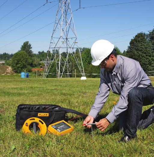
2 Why ground, why test? Why ground? Poor grounding not only contributes to unnecessary downtime, but a lack of good grounding is also dangerous and increases the risk of equipment failure. Without an effective grounding system, we could be exposed to the risk of electric shock, not to mention instrumentation errors, harmonic distortion issues, power factor problems and a host of possible intermittent dilemmas. If fault currents have no path to the ground through a properly designed and maintained grounding system, they will find unintended paths that could include people. The following organizations have recommendations and/or standards for grounding to ensure safety: OA (Occupational afety ealth Administration) NFPA (National Fire Protection Association) ANI/IA (American National tandards Institute and Instrument ociety of America) TIA (Telecommunications Industry Association) IC (International lectrotechnical Commission) CNLC (uropean Committee for lectrotechnical tandardization) I (Institute of lectrical and lectronics ngineers) owever, good grounding isn t only for safety; it is also used to prevent damage to industrial plants and equipment. A good grounding system will improve the reliability of equipment and reduce the likelihood of damage due to lightning or fault currents. Billions are lost each year in the workplace due to electrical fires. This does not account for related litigation costs and loss of personal and corporate productivity. Why test grounding systems? What is a good ground resistance value? Over time, corrosive soils with high moisture content, high salt content, and high temperatures can degrade ground rods and their connections. o although the ground system, when initially installed, had low earth ground resistance values, the resistance of the grounding system can increase if the ground rods are eaten away. Grounding testers, like the Fluke 16- and 165-, are indispensable troubleshooting tools to help you maintain uptime. With frustrating, intermittent electrical problems, the problem could be related to poor grounding or poor power quality. That is why it is highly recommended that all grounds and ground connections are checked at least annually as a part of your normal Predictive Maintenance plan. During these periodic checks, if an increase in resistance of more than 0 % is measured, the technician should investigate the source of the problem, and make the correction to lower the resistance, by replacing or adding ground rods to the ground system. There is a good deal of confusion as to what constitutes a good ground and what the ground resistance value needs to be. Ideally a ground should be of zero ohms resistance. There is not one standard ground resistance threshold that is recognized by all agencies. owever, the NFPA and I have recommended a ground resistance value of 5.0 ohms or less. The NC has stated to Make sure that system impedance to ground is less than 5 ohms specified in NC In facilities with sensitive equipment it should be 5.0 ohms or less. The Telecommunications industry has often used 5.0 ohms or less as their value for grounding and bonding. The goal in ground resistance is to achieve the lowest ground resistance value possible that makes sense economically and physically. Table of contents Why ground? Why test? Why test? Corrosive soils. Grounding basics 6 Methods of earth ground testing Why ground? Lightning strikes. 1 Measuring ground resistance What is a ground and what does it do? The NC, National lectrical Code, Article 100 defines a ground as: a conducting connection, whether intentional or accidental between an electrical circuit or equipment and the earth, or to some conducting body that serves in place of the earth. When talking about grounding, it is actually two different subjects: earth grounding and equipment grounding. arth grounding is an intentional connection from a circuit conductor, usually the neutral, to a ground electrode placed in the earth. quipment grounding ensures that operating equipment within a structure is properly grounded. These two grounding systems are required to be kept separate except for a connection between the two systems. This prevents differences in voltage potential from a possible flashover from lightning strikes. The purpose of a ground besides the protection of people, plants and equipment is to provide a safe path for the dissipation of fault currents, lightning strikes, static discharges, MI and RFI signals and interference. Use the Fluke 165- to determine the health of your earth ground systems.
3 Grounding basics Components of a ground electrode Ground conductor Connection between the ground conductor and the ground electrode Ground electrode Locations of resistances (a) The ground electrode and its connection The resistance of the ground electrode and its connection is generally very low. Ground rods are generally made of highly conductive/low resistance material such as steel or copper. (b) The contact resistance of the surrounding earth to the electrode The National Institute of tandards (a governmental agency within the U Dept. of Commerce) has shown this resistance to be almost negligible provided that the ground electrode is free of paint, grease, etc. and that the ground electrode is in firm contact with the earth. (c) The resistance of the surrounding body of earth The ground electrode is surrounded by earth which conceptually is made up of concentric shells all having the same thickness. Those shells closest to the ground electrode have the smallest amount of area resulting in the greatest degree of resistance. ach subsequent shell incorporates a greater area resulting in lower resistance. This finally reaches a point where the additional shells offer little resistance to the ground surrounding the ground electrode. o based on this information, we should focus on ways to reduce the ground resistance when installing grounding systems. What affects the grounding resistance? First, the NC code (1987, 50-8-) requires a minimum ground electrode length of.5 meters (8.0 feet) to be in contact with soil. But, there are four variables that affect the ground resistance of a ground system: 1. Length/depth of the ground electrode. Diameter of the ground electrode. Number of ground electrodes. Ground system design Length/depth of the ground electrode One very effective way of lowering ground resistance is to drive ground electrodes deeper. oil is not consistent in its resistivity and can be highly unpredictable. It is critical when installing the ground electrode that it is below the frost line. This is done so that the resistance to ground will not be greatly influenced by the freezing of the surrounding soil. Generally, by doubling the length of the ground electrode you can reduce the resistance level by an additional 0 %. There are occasions where it is physically impossible to drive ground rods deeper areas that are composed of rock, granite, etc. In these instances, alternative methods including grounding cement are viable. Diameter of the ground electrode Increasing the diameter of the ground electrode has very little effect in lowering the resistance. For example, you could double the diameter of a ground electrode and your resistance would only decrease by 10 %. Number of ground electrodes Another way to lower ground resistance is to use multiple ground electrodes. In this design, more than one electrode is driven into the ground and connected in parallel to lower the resistance. For additional electrodes to be effective, the spacing of additional rods need to be at least equal to the depth of the driven rod. Without proper spacing of the ground electrodes, their spheres of influence will intersect and the resistance will not be lowered. To assist you in installing a ground rod that will meet your specific resistance requirements, you can use the table of ground resistances, below. Remember, this is to only be used as a rule of thumb, because soil is in layers and is rarely homogenous. The resistance values will vary greatly. Ground system design imple grounding systems consist of a single ground electrode driven into the ground. The use of a single ground electrode is the most common form of grounding and can be found outside your home or place of business. Complex grounding systems consist of multiple ground rods, connected, mesh or grid networks, ground plates, and ground loops. These systems are typically installed at power generating substations, central offices, and cell tower sites. Complex networks dramatically increase the amount of contact with the surrounding earth and lower ground resistances. Type of soil Very moist soil, swamplike Farming soil, loamy and clay soils oil resistivity R Ground electrode depth (meters) ach ground electrode has its own sphere of influence. arthing resistance arthing strip (meters) ΩM Ground systems ingle ground electrode Multiple ground electrodes connected Mesh network andy clay soil Moist sandy soil Concrete 1: Moist gravel Dry sandy soil Dry gravel toney soil 0, Rock Ground plate 5
4 What are the methods of earth ground testing? There are four types of earth ground testing methods available: oil Resistivity (using stakes) Fall-of-Potential (using stakes) elective (using 1 clamp and stakes) takeless (using clamps only) oil resistivity measurement Why determine the soil resistivity? oil Resistivity is most necessary when determining the design of the grounding system for new installations (green field applications) to meet your ground resistance requirements. Ideally, you would find a location with the lowest possible resistance. But as we discussed before, poor soil conditions can be overcome with more elaborate grounding systems. The soil composition, moisture content, and temperature all impact the soil resistivity. oil is rarely homogenous and the resistivity of the soil will vary geographically and at different soil depths. Moisture content changes seasonally, varies according to the nature of the sub layers of earth, and the depth of the permanent water table. ince soil and water are generally more stable at deeper strata, it is recommended that the ground rods be placed as deep as possible into the earth, at the water table if possible. Also, ground rods should be installed where there is a stable temperature, i.e. below the frost line. For a grounding system to be effective, it should be designed to withstand the worst possible conditions. ow do I calculate soil resistivity? ow do I measure soil resistance? The measuring procedure described below uses the universally accepted Wenner method developed by Dr. Frank Wenner of the U Bureau of tandards in (F. Wenner, A Method of Measuring arth Resistivity; Bull, National Bureau of tandards, Bull 1() 58, p. 7896; 1915/16.) To test soil resistivity, connect the ground tester as shown below. As you can see, four earth ground stakes are positioned in the soil in a straight line, equidistant from one another. The distance between earth ground stakes should be at least three times greater than the stake depth. o if the depth of each ground stake is one foot (0 centimeters), make sure the distance between stakes is greater than three feet (91 centimeters). The Fluke 165- generates a known current through the two outer ground stakes and the drop in voltage potential is measured between the two inner ground stakes. Using Ohm s Law (V = IR), the Fluke tester automatically calculates the soil resistance. Because measurement results are often distorted and invalidated by underground pieces of metal, underground aquifers, etc. additional measurements where the stake s axis are turned 90 degrees is always recommended. By changing the depth and distance several times, a profile is produced that can determine a suitable ground resistance system. oil resistivity measurements are often corrupted by the existence of ground currents and their harmonics. To prevent this from occurring, the Fluke 165- uses an Automatic Frequency Control (AFC) ystem. This automatically selects the testing frequency with the least amount of noise enabling you to get a clear reading. The formula is as follows: r = π A R (r = the average soil resistivity to depth A in ohm cm) π =.116 A = the distance between the electrodes in cm R = t he measured resistance value in ohms from the test instrument Note: Divide ohm centimeters by 100 to convert to ohm meters. Just watch your units. xample: You have decided to install one meter long ground rods as part of your grounding system. To measure the soil resistivity at a depth of one meter, we discussed a spacing between the test electrodes of three meters ADVANCD ART / GROUND R GO /C arth/ground Resistance 00kΩ CANG ITM POL POL POL POL 00kΩ /P Resistance kω POL POL POL POL /P1 /C1 LCT To measure the soil resistivity start the Fluke 165- and read the resistance value in ohms. In this case assume the resistance reading is 100 ohms. o, in this case we know: A = 1 meter, and R = 100 ohms Then the soil resistivity would equal: r= xπxaxr r = x.116 x 1 meter x 100 ohms r = 1885 Ωm etup for soil resistivity testing using the Fluke 16- or / a a 6 a a 7
 value. This is the actual value of the ground electrode under test.")
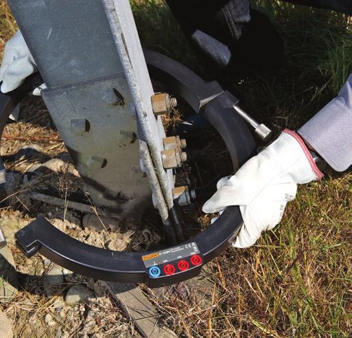
5 What are the methods of earth ground testing? Law (V = IR), the tester automatically calculates the resistance of the earth electrode. Connect the ground tester as shown in the picture. Press and read out the R (resistance) value. This is the actual value of the ground electrode under test. If this ground electrode is in parallel or series with other ground rods, the R value is the total value of all resistances ADVANCD ART / GROUND R GO /C arth/ground Resistance 00kΩ CANG ITM POL POL POL POL 00kΩ /P Resistance kω POL POL POL POL /P1 LCT /C1 ow do you place the stakes? arth electrode >0 m (65 ft) Inner stake Outer stake >0 m (65 ft) Fall-of-Potential measurement The Fall-of-Potential test method is used to measure the ability of an earth ground system or an individual electrode to dissipate energy from a site. ow does the Fall-of-Potential test work? First, the earth electrode of interest must be disconnected from its connection to the site. econd, the tester is connected to the earth electrode. Then, for the -pole Fall-of-Potential test, two earth stakes are placed in the soil in a direct line away from the earth electrode. Normally, spacing of 0 meters (65 feet) is sufficient. For more detail on placing the stakes, see the next section. A known current is generated by the Fluke 165- between the outer stake (auxiliary earth stake) and the earth electrode, while the drop in voltage potential is measured between the inner earth stake and the earth electrode. Using Ohm s 8 To achieve the highest degree of accuracy when performing a pole ground resistance test, it is essential that the probe is placed outside the sphere of influence of the ground electrode under test and the auxiliary earth. If you do not get outside the sphere of influence, the effective areas of resistance will overlap and invalidate any measurements that you are taking. The table is a guide for appropriately setting the probe (inner stake) and auxiliary ground (outer stake). To test the accuracy of the results and to ensure that the ground stakes are outside the spheres of influence, reposition the inner stake (probe) 1 meter ( feet) in either direction and take a fresh measurement. If there is a significant change in the reading (0 %), you need to increase the distance between the ground rod under test, the inner stake (probe) and the outer stake (auxiliary ground) until the measured values remain fairly constant when repositioning the inner stake (probe). Depth of the ground electrode Distance to the inner stake Distance to the outer stake m 15 m 5 m m 0 m 0 m 6m 5 m 0 m 10 m 0 m 50 m elective measurement elective testing is very similar to the Fall-of-Potential testing, providing all the same measurements, but in a much safer and easier way. This is because with elective testing, the earth electrode of interest does not need to be disconnected from its connection to the site! The technician does not have to endanger himself by disconnecting ground, nor endanger other personnel or electrical equipment inside a nongrounded structure. Just as with the Fall-of-Potential test, two earth stakes are placed in the soil in a direct line, away from the earth electrode. Normally, spacing of 0 meters (65 feet) is sufficient. The tester is then connected to the earth electrode of interest, with the advantage that the connection to the site doesn t need to be disconnected. Instead, a special clamp is placed around the earth electrode, which eliminates the effects of parallel resistances in a grounded system, so only the earth electrode of interest is measured. Just as before, a known current is generated by the Fluke 165- between the outer stake (auxiliary earth stake) and the earth electrode, while the drop in voltage potential is measured between the inner earth stake and the earth electrode. Only the current flowing through the earth electrode of interest is measured using the clamp. The generated current will also flow through other parallel resistances, but only the current through the clamp (i.e. the current through the earth electrode of interest) is used to calculate resistance (V = IR). If the total resistance of the ground system should be measured, then each earth electrode resistance must be measured by placing the clamp around each individual earth electrode. Then the total resistance of the ground system can be determined by calculation. Testing individual ground electrode resistances of high voltage transmission towers with overhead ground or static wire, requires that these wires be disconnected. If a tower has more than one ground at its base, these must also be disconnected one by one and tested. owever, the Fluke 165- has an optional accessory, a 0 mm (1.7 in) diameter clamp-on current transformer, which can measure the individual resistances of each leg, without disconnecting any ground leads or overhead static/ground wires. Connect the ground tester as shown. Press and read out the R value. This is the actual resistance value of the ground electrode under test. 9
6 What are the methods of earth ground testing? ource TNFORMR I-16 CURRNT Measure I-16 NIN TNF X G CURR ORMR NT 165- ADVANCD ART / GROUND R GO /C arth/ground Resistance 00kΩ CANG ITM POL POL POL POL POL 00kΩ /P Resistance kω POL POL POL /P1 /C1 LCT Test current paths in the stakeless method ADVANCD ART / GROUND R GO /C arth/ground Resistance 00kΩ CANG ITM POL POL POL POL POL 00kΩ /P Resistance kω POL POL POL /P1 LCT /C1 I-16 IND T UCING NF CUR OR M RNT R takeless measurement Ground impedance measurements The Fluke 165- earth ground tester is able to measure earth ground loop resistances for multigrounded systems using only current clamps. This test technique eliminates the dangerous and time consuming activity of disconnecting parallel grounds, as well as the process of finding suitable locations for auxiliary ground stakes. You can also perform earth ground tests in places you have not considered before: inside buildings, on power pylons or anywhere you don t have access to soil. With this test method, two clamps are placed around the earth ground rod or the connecting cable and each are connected to the tester. arth ground stakes are not used at all. A known voltage is induced by one clamp, and the current is measured using the second clamp. The tester automatically determines the ground loop resistance at this ground rod. If there is only one path to ground, like at many residential situations, the takeless method will not provide an acceptable value and the Fall-of-Potential test method must be used. The Fluke 165- works on the principle that in parallel/multi-grounded systems, the net resistance of all ground paths will be extremely low as compared to any single path (the one under test). o, the net resistance of all the parallel return path resistances is effectively zero. takeless measurement only measures individual ground rod resistances in parallel to earth grounding systems. If the ground system is not parallel to earth then you will either have an open circuit, or be measuring ground loop resistance. When attempting to calculate possible short circuit currents in power plants and other high voltage/current situations, determining the complex grounding impedance is important since the impedance will be made up of inductive and capacitive elements. Because inductivity and resistivity are known in most cases, actual impedance can be determined using a complex computation. ince impedance is frequency dependent, the Fluke 165- uses a 55 z signal for this calculation to be as close to voltage operating frequency as possible. This ensures that the measurement is close to the value at the true operating frequency. Using this feature of the Fluke 165-, accurate direct measurement of grounding impedance is possible. Power utilities technicians, testing high voltage transmission lines, are interested in two things: the ground resistance in case of a lightning strike, and the impedance of the entire system in case of a short circuit on a specific point in the line. hort circuit, in this case, means an active wire breaks loose and touches the metal grid of a tower. Two-pole ground resistance In situations where the driving of ground stakes is neither practical nor possible, the Fluke 16- and 165- testers give you the ability to do two-pole ground resistance/ continuity measurements, as shown below. To perform this test, the technician must have access to a good, known ground such as an all metal water pipe. The water pipe should be extensive enough and be metallic throughout without any insulating couplings or flanges. Unlike many testers, the Fluke 16- and 165- perform the test with a relatively high current (short circuit current > 50 ma) ensuring stable results ADVANCD ART / GROUND R GO /C T arth/ground Resistance 00kΩ CANG ITM POL POL POL POL POL /P 00kΩ Resistance kω POL POL POL /P1 LCT /C1 I-16X N ING CURR TN NT FOR MR etup for the stakeless method using the >10 cm ( in) quivalent circuit for two-point measurement
 within the central office to determine the type of grounding system that exists.")
7 The layout of a typical central office. At central offices When conducting a grounding audit of a central office there are three different measurements required. Before testing, locate the B (Master Ground Bar) within the central office to determine the type of grounding system that exists. As shown on this page, the B will have ground leads connecting to the: N (Multi-Grounded Neutral) or incoming service, ground field, water pipe, and structural or building steel R NING TNFORM CANG ITM POL POL POL POL 00kΩ /P Resistance kω POL POL POL POL /P1 /C1 LCT CURRNT RMR Building steel arth/ground Resistance 00kΩ I-16 Water pipe TNFO Ground field /C B CURRN RMR T N 165- ADVANCD ART / GROUND R GO I-16 X B To prove this, you need to perform a few additional tests on individual resistances. First, perform the -pole Fall-of-Potential test on each leg off the B and record each measurement. Using Ohm s Law again, these measurements should be equal to the resistance of the entire system. From the calculations you will see that you are from 0 % to 0 % off the total R value. Finally, measure the resistances of the various legs of the B using the elective takeless method. It works like the takeless method, but it differs in the way we use the two separate clamps. We place the inducing voltage clamp around the cable going to the B, and since the B is connected to the incoming power, which is parallel to the earth system, we have achieved that requirement. Take the sensing clamp and place it around the ground cable leading out to the ground field. When we measure the resistance, this is the actual resistance of the ground field, plus the parallel path of the B. And because it should be very low ohmically, it should have no real effect on the measured reading. This process can be repeated for the other legs of the ground bar i.e. water pipe and structural steel. To measure the B via the takeless elective method, place the inducing voltage clamp around the line to the water pipe (since the copper water pipe should have very low resistance) and your reading will be the resistance for only the N. NING TNFO First, perform the takeless test on all the individual grounds coming off of the B. The purpose is to ensure that all the grounds are connected, especially the N. It is important to note that you are not measuring the individual resistance, rather the loop resistance of what you are clamped around. As shown in Figure 1, connect the Fluke 165- or 16- and both the inducing and sensing clamps, which are placed around each connection to measure the loop resistance of the N, the ground field, the water pipe, and the building steel. econd, perform the -pole Fall-of-Potential test of the entire ground system, connecting to the B as illustrated in Figure. To get to remote earth, many phone companies utilize unused cable pairs going out as much as a mile. Record the measurement and repeat this test at least annually. Third, measure the individual resistances of the ground system using the elective test of the Fluke 165- or 16-. Connect the Fluke tester, as shown in Figure. Measure the resistance of the N; the value is the resistance of that particular leg of the B. Then measure the ground field. This reading is the actual resistance value of the central office ground field. Now move on to the water pipe, and then repeat for the resistance of the building steel. You can easily verify the accuracy of these measurements through Ohm s Law. The resistance of the individual legs, when calculated, should equal the resistance of the entire system given (allow for reasonable error since all ground elements may not be measured). These test methods provide the most accurate measure of a central office, because it gives you the individual resistances and their actual behavior in a ground system. Although accurate, the measurements would not show how the system behaves as a network, because in the event of a lightning strike or fault current, everything is connected. I-16XCURRNT Measuring ground resistance GN M Figure 1: takeless testing of a central office. Figure : Perform the -Pole Fall-of-Potential test of the entire ground system ADVANCD ART / GROUND R GO /C arth/ground Resistance 00kΩ POL POL POL 00kΩ Resistance kω POL POL POL POL POL CANG ITM /P /P1 /C1 LCT B N Figure : Measure the individual resistances of the ground system using the elective test ADVANCD ART / GROUND R GO /C arth/ground Resistance 00kΩ POL POL POL POL CANG ITM POL 00kΩ /P Resistance kω POL POL POL /P1 /C1 LCT I-16 CURRNT TNFORMR B N TNFORMR CURRNT I-16 I-16 TNFORMR CURRNT I-16 TNFORMR CURRNT 1 1


8 I-16X CANG ITM LCT I-16 CANG ITM LCT 165- ADVANCD ART / GROUND R GO arth/ground Resistance 00kΩ 00kΩ Resistance kω POL POL POL POL POL POL POL POL 165- ADVANCD ART / GROUND R GO arth/ground Resistance 00kΩ 00kΩ Resistance kω POL POL POL POL POL POL POL POL I-16X /C /P /P1 /C1 /C /P /P1 /C1 More ground resistance applications A typical setup at a cellular tower installation. Application sites There are four other particular applications where you can use the Fluke 165- to measure the capability of the earth ground system. Cellular sites/microwave and radio towers At most locations there is a -legged tower with each leg individually grounded. These grounds are then connected with a copper cable. Next to the tower is the Cell site building, housing all the transmission equipment. Inside the building there is a halo ground and a B, with the halo ground connected to the B. The cell site building is grounded at all corners connected to the B via a copper cable and the corners are also interconnected via copper wire. There is also a connection between the building ground ring and the tower ground ring. lectrical substations A substation is a subsidiary station on a transmission and distribution system where voltage is normally transformed from a high value to low value. A typical substation will contain line termination structures, high-voltage switchgear, one or more power transformers, low-voltage switchgear, surge protection, controls, and metering. Remote switching sites Remote switching sites are also known as slick sites, where digital line concentrators and other telecommunications equipment is operating. The remote site is typically grounded at either end of the cabinet and then will have a series of ground stakes around the cabinet connected by copper wire. Lightning protection at commercial/ industrial sites Most lightning fault current protection systems follow the design of having all four corners of the building grounded and these are usually connected via a copper cable. Depending on the size of the building and the resistance value that it was designed to achieve, the number of ground rods will vary. Recommended tests nd users are required to perform the same three tests at each application: takeless measurement, -pole Fall-of-Potential measurement and elective measurement. takeless measurement First, perform a takeless measurement on: The individual legs of the tower and the four corners of the building (cell sites/towers) All grounding connections (electrical substations) The lines running to the remote site (remote switching) The ground stakes of the building (lightning protection) For all applications, this is not a true ground resistance measurement because of the network ground. This is mainly a continuity test to verify that the site is grounded, that we have an electrical connection, and that the system can pass current. -pole Fall-of-Potential measurement econd, we measure the resistance of the entire system via the -pole Fall-of-Potential method. Keep in mind the rules for stake setting. This measurement should be recorded and measurements should take place at least twice per year. This measurement is the resistance value for the entire site. elective measurement Lastly, we measure the individual grounds with the elective test. This will verify the integrity of the individual grounds, their connections, and determine whether the grounding potential is fairly uniform throughout. If any of the measurements show a greater degree of variability than the other ones, the reason for this should be determined. The resistances should be measured on: ach leg of the tower and all four corners of the building (cell sites/towers) Individual ground rods and their connections (electrical substations) Both ends of the remote site (remote switching) All four corners of the building (lightning protection) NING CURRNT TNFORMR CURRNT TNFORMR NING CURRNT TNFORMR A typical setup at an electrical substation. Using takeless testing at a remote switching site. Using elective testing on a lightning protection system. 1 15

 takeless testing (using clamps only) The complete model kit comes with the Fluke 16- or 165-")


 -585 or Fax (5) 6-5116 In urope/m-ast/africa +1 (0) 0 675 00 or Fax +1 (0) 0 675 In Canada (800)-6-FLUK or Fax (905)")
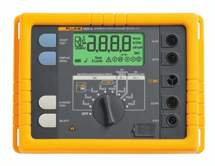
9 arth ground products Fluke 165- Advanced GO arth Ground Tester Fluke 16- Basic GO arth Ground Tester The most complete tester The Fluke 16- and 165- are distinctive earth ground testers that can perform all four types of earth ground measurement: -and -pole Fall-of-Potential (using stakes) -pole soil resistivity testing (using stakes) elective testing (using 1 clamp and stakes) takeless testing (using clamps only) The complete model kit comes with the Fluke 16- or 165- tester, a set of two leads, earth ground stakes, cable reels with wire, clamps, batteries and manual all inside a rugged Fluke carrying case. Fluke 165- advanced features Advanced features of the Fluke 165- include: Automatic Frequency Control (AFC) identifies existing interference and chooses a measurement frequency to minimize its effect, providing more accurate earth ground values R* Measurement calculates earth ground impedance with 55 z to more accurately reflect the earth ground resistance that a fault-to-earth ground would see Adjustable Limits for quicker testing Optional accessories 0 mm (1.7 in) plit Core Transformer for performing selective testing on individual legs of towers. Comparing earth ground testers Product Fall of Potential elective takeless -Pole method -Pole -Pole/oil 1 Clamp Clamp Pole Fluke 161 Fluke 16- Fluke 165- Fluke 160 Product The complete kit Fluke 160 kit Fluke. The Most Trusted Tools in the World. Fluke Corporation PO Box 9090, verett, WA 9806 U..A. Fluke urope B.V. PO Box 1186, 560 BD indhoven, The Netherlands For more information call: In the U..A. (800) -585 or Fax (5) In urope/m-ast/africa +1 (0) or Fax +1 (0) In Canada (800)-6-FLUK or Fax (905) From other countries +1 (5) or Fax +1 (5) Web access: 01 Fluke Corporation. pecifications subject to change without notice. Printed in U..A. 1/01 668A_N Modification of this document is not permitted without written permission from Fluke Corporation.
Earth Grounding Resistance
 Earth Grounding Resistance Principles, testing methods and applications DIAGSE intermittent electrical problems AVOID unnecessary downtime LEARN earth ground safety principles Why ground, why test? Why
High Voltage Pylon earth Measurements. Tycom (Pty) Ltd Frank Barnes Comtest (Pty) Ltd Presented by Gavin van Rooy
 Ltd Frank Barnes Comtest (Pty) Ltd Presented by Gavin van Rooy") High Voltage Pylon earth Measurements Tycom (Pty) Ltd Frank Barnes Comtest (Pty) Ltd Presented by Gavin van Rooy Abstract The earth connection of high voltage electrical power line pylons is obviously
High Voltage Pylon earth Measurements Tycom (Pty) Ltd Frank Barnes Comtest (Pty) Ltd Presented by Gavin van Rooy Abstract The earth connection of high voltage electrical power line pylons is obviously
High Voltage Pylon Earth Measurements
 High Voltage Pylon Earth Measurements Speaker: Gavin van Rooy Authors: Frank Barnes and Gavin van Rooy Tycom (Pty) Ltd PO Box 3546, Randburg, 2125, South Africa E-mail: frank@tycom.co.za Phone: 011 787
PERFORMANCE ASSESSMENT OF SUBSTATION SITE EARTHING USING FLUKE 1625 GROUND TESTER
 Nigerian Journal of Technology (NIJOTECH) Vol. 32, No. 1, March, 2013, pp. 49 53. Copyright 2013 Faculty of Engineering, University of Nigeria. ISSN 1115-8443 PERFORMANCE ASSESSMENT OF SUBSTATION SITE
Stake-less earth / ground testing
 APPLICATION NOTE Stake-less earth / ground testing NEW DET14C and DET24C CLAMPS GETTING-AROUND ANY CHALLENGE What is stake-less testing? How does it work? Where and how can it be used? What are the potential
Safety Issues Caused by High Earth Resistance and Identifying Them Using Instruments
 Safety Issues Caused by High Earth Resistance and Identifying Them Using Instruments Thomas Szollossy Senior Technical Support Engineer Power Quality Thailand PQSynergy 2017, Chiang Mai, Thailand Introduction
Industrial and Commercial Power Systems Topic 7 EARTHING
 The University of New South Wales School of Electrical Engineering and Telecommunications Industrial and Commercial Power Systems Topic 7 EARTHING 1 INTRODUCTION Advantages of earthing (grounding): Limitation
Fluke and
 Fluke 1623-2 and 1625-2 GEO Earth Ground Testers Technical Data The new Fluke 1623-2 and 1625-2 GEO Earth Ground Testers offer data storage and download capabilities via USB port. World class accessories
EPG. by Chris C. Kleronomos
 April 1994 EFFECTIVE EQUIPMENT GROUNDING ECOS Electronics Corporation by Chris C. Kleronomos The quality of the electrical wiring and grounding in a facility containing sensitive electronic equipment is
Safety earthing. Sector Energy PTI NC. Copyright Siemens AG All rights reserved. Theodor Connor
 Safety earthing Sector Energy PTI NC Theodor Connor Copyright Siemens AG 2008. All rights reserved. Content Introduction Theoretical background Soil Analysis Design of earthing system Measurements on earthing
Grounding and Lightning arrestors
 CHAPTER - Four Grounding and Lightning arrestors 4.1. Introduction Electrical connection of neutral point of a supply system or the non current carrying part of electrical equipments to the general mass
Outdoor Installation 2: Lightning Protection and Grounding
 Outdoor Installation 2: Lightning Protection and Grounding Training materials for wireless trainers This one hour talk covers lightning protection, grounding techniques and problems, and electrolytic incompatibility.
UNDERSTANDING. Ground Resistance Testing. I Voltmeter (E) Grounding. electrode. under test. Ground rod and clamp
 Grounding. electrode. under test. Ground rod and clamp") UNDERSTANDING Ground Resistance Testing Current supply E Ammeter (I) I Voltmeter (E) Grounding electrode under test X Auxiliary potential electrode Y Auxiliary current electrode Z R Rx R1 R2 Rn-1 Rn EARTH
UNDERSTANDING Ground Resistance Testing Current supply E Ammeter (I) I Voltmeter (E) Grounding electrode under test X Auxiliary potential electrode Y Auxiliary current electrode Z R Rx R1 R2 Rn-1 Rn EARTH
Fluke 1623 and GEO Earth Ground Testers. Technical Data. Stakeless testing
 Fluke 1623 and 1625 GEO Earth Ground Testers Technical Data The new Fluke 1623 and 1625 GEO Earth Ground Testers offer an innovative solution, called Stakeless testing, to make your earth ground loop resistance
Earthing of Electrical Devices and Safety
 Earthing of Electrical Devices and Safety JOŽE PIHLER Faculty of Electrical Engineering and Computer Sciences University of Maribor Smetanova 17, 2000 Maribor SLOVENIA joze.pihler@um.si Abstract: - This
Grounding for Power Quality
 Presents Grounding for Power Quality Grounding for Power Quality NEC 250.53 states that ground resistance should be less than 25 ohms. Is this true? Grounding for Power Quality No! NEC 250.53 states
UNDERSTANDING. Ground Resistance Testing. Soil Resistivity. Ground Resistance. 3-Point Measurements. 4-Point Measurements. Clamp-On Measurements
 UNDERSTANDING Ground Resistance Testing Current supply E Ammeter (I) I Voltmeter (E) Ground electrode under test X Auxiliary potential electrode Y Auxiliary current electrode Z R Rx R1 R2 Rn-1 Rn EARTH
Field Instruction. Induced voltages can occur in overhead lines, underground cables, or in switchyards.
 8.3 Induced Voltage Purpose The purpose of this instruction is to provide awareness of Electrostatic and Electromagnetic induced voltages and the method required to reduce or eliminate it. An induced voltage
Power Quality. Case Study. Conrad Bottu Laborelec January 2008
 Case Study Electromagnetic compatibility (EMC) study Breakdown of low voltage electronic equipment in a 25 kv substation Conrad Bottu Laborelec January 2008 Power Quality Power Quality 1 Introduction Description
There are a wide variety of ground resistance testers available on the
 Featured Products: Choosing the Right Ground Resistance Tester There are a wide variety of ground resistance testers available on the market today. These vary in design, features, and complexity, and include
GROUND TESTERS For all of your Ground Testing needs...
 GROUND TESTERS For all of your Ground Testing needs... An array of Ground Testers to choose from Whether you are doing a simplified 2-Point, a more complete 3- or 4-Point Fall-of-Potential test, a soil
Cable Protection against Earth Potential Rise due to Lightning on a Nearby Tall Object
 Cable Protection against Earth Potential Rise due to Lightning on a Nearby Tall Object U. S. Gudmundsdottir, C. F. Mieritz Abstract-- When a lightning discharge strikes a tall object, the lightning current
AC Voltage- Pipeline Safety and Corrosion MEA 2015
 AC Voltage- Pipeline Safety and Corrosion MEA 2015 WHAT ARE THE CONCERNS ASSOCIATED WITH AC VOLTAGES ON PIPELINES? AC concerns Induced AC Faults Lightning Capacitive coupling Safety Code Induced AC Corrosion
Evaluation of Soil Resistivity Characteristics forsubstation Grounding: a Case Study of a University Campus in South-West Zone, Nigeria
 Evaluation of Soil Resistivity Characteristics forsubstation Grounding: a Case Study of a University Campus in South-West Zone, Nigeria Adegboyega Gabriel A Bells University of Technology, Ota, Nigeria
RADIO AND TELEVISION SATELLITE EQUIPMENT
 ARTICLE 810 RADIO AND TELEVISION SATELLITE EQUIPMENT Introduction to Article 810 Radio and Television Satellite Equipment This article covers transmitter and receiver (antenna) equipment and the wiring
Understand the importance of Ground Resistance Testing & much more! (800) (508)
 (508)") Soil Resistivity Ground Resistance 3-Point Measurements 4-Point Measurements Clamp-On Measurements Understand the importance of Ground Resistance Testing & much more! (800) 343-1391 (508) 698-2115 www.aemc.com
Soil Resistivity Ground Resistance 3-Point Measurements 4-Point Measurements Clamp-On Measurements Understand the importance of Ground Resistance Testing & much more! (800) 343-1391 (508) 698-2115 www.aemc.com
Earth/ground measurement guide
 ARA CO.,LTD. 1694, 1694/1 Prachasongkhro Road, Dindaeng, Dindaeng, Bangkok 10400 Tel. 02-692-3980, Fax. 02-692-3978 -mail: sales@asras.com www.asras.com; www.asras.co.th arth/ground resistance an soil
Attendee Announcements
 Attendee Announcements Seminar Raffle Be sure to drop your raffle ticket in the drum at today s Keynote located in the Mile High Ballroom. You have a chance to win a $250 American Express Gift Card. One
LIGHTNING EARTHING SYSTEM : A PRACTICAL GUIDE
 International Lightning Protection Association 1 st Symposium Valencia Spain 24th 25th of November, 2011 LIGHTNING EARTHING SYSTEM : A PRACTICAL GUIDE Alain Rousseau SEFTIM (France) ABSTRACT To make a
Device Interconnection
 Device Interconnection An important, if less than glamorous, aspect of audio signal handling is the connection of one device to another. Of course, a primary concern is the matching of signal levels and
Understanding Soil Resistivity Testing
 Technical Hotline: (0) -9 Technical Hotline: (0) -9 www.aemc.com www.aemc.com Understanding Testing Effects of on Ground Electrode Resistance Factors Affecting APPLICATION NOTES OCTOBER Understanding Testing
Overview of Grounding for Industrial and Commercial Power Systems Presented By Robert Schuerger, P.E.
 Overview of Grounding for Industrial and Commercial Power Systems Presented By Robert Schuerger, P.E. HP Critical Facility Services delivered by EYP MCF What is VOLTAGE? Difference of Electric Potential
CONTINUING EDUC ATION
 3 CONTINUING EDUC ATION FOR WISCONSIN ELECTRICIANS 2017 NEC Article 250 2 Hours WISCONSIN CONTRACTORS INSTITUTE N16 W23217 Stone Ridge Drive Suite 290 Waukesha, WI 53188 262-409-4282 www.wcitraining.com
SDCS-03 DISTRIBUTION NETWORK GROUNDING CONSTRUCTION STANDARD (PART-I) UNDERGROUND NETWORK GROUNDING. Rev. 01
 UNDERGROUND NETWORK GROUNDING. Rev. 01") SDCS-03 DISTRIBUTION NETWORK GROUNDING CONSTRUCTION STANDARD (PART-I) UNDERGROUND NETWORK GROUNDING Rev. 01 This specification is property of SEC and subject to change or modification without any notice
SDCS-03 DISTRIBUTION NETWORK GROUNDING CONSTRUCTION STANDARD (PART-I) UNDERGROUND NETWORK GROUNDING Rev. 01 This specification is property of SEC and subject to change or modification without any notice
SDCS-03 DISTRIBUTION NETWORK GROUNDING CONSTRUCTION STANDARD (PART-II) OVERHEAD NETWORK GROUNDING. Rev. 01
 OVERHEAD NETWORK GROUNDING. Rev. 01") SEC DISTRIBUTION GROUNDING STANDARD SDCS-03 Part-II Rev.01 SDCS-03 DISTRIBUTION NETWORK GROUNDING CONSTRUCTION STANDARD (PART-II) OVERHEAD NETWORK GROUNDING Rev. 01 This specification is property of SEC
SEC DISTRIBUTION GROUNDING STANDARD SDCS-03 Part-II Rev.01 SDCS-03 DISTRIBUTION NETWORK GROUNDING CONSTRUCTION STANDARD (PART-II) OVERHEAD NETWORK GROUNDING Rev. 01 This specification is property of SEC
FALL-OF-POTENTIAL GROUND RESISTANCE TESTER
 FALL-OF-POTENTIAL GROUND RESISTANCE TESTER Models 3620, 3640 & 4610 Call toll free (800) 537-0351 or visit www.allspec.com Measures soil resistivity (4-Point) (Model 4610) Measures ground resistance (2-
HV Substation Earthing Design for Mines
 International Journal of Engineering Research and Development e-issn: 2278-067X, p-issn: 2278-800X, www.ijerd.com Volume 4, Issue 6 (October 2012), PP. 100-107 HV Substation Earthing Design for Mines M.
Fluke Clamp Meters Solutions for every need
 Fluke Clamp Meters Solutions for every need 381 355 773 more solutions inside Clamp Meter selection chart Job functions Applications Recommended clamp Process Technician/ Automation Specialist Multiple
Soil Resistivity Ground Resistance 3-Point Measurements 4-Point Measurements Clamp-On Measurements
 Soil Resistivity Ground Resistance 3-Point Measurements 4-Point Measurements Clamp-On Measurements 200 Foxborough Blvd. Foxborough, MA 02035 (800) 343-1391 (508) 698-2115 FAX (508) 698-2118 sales@aemc.com
Instruction Manual. TT1000 Tower Earth Tester. Rev 01
 Instruction Manual TT1000 Tower Earth Tester Rev 01 Contents 1 Introduction... 3 2 Features... 3 3 Operation... 4 3.1 Test Lead Configuration... 5 3.2 Probe Integrity Test... 6 3.3 Impedance measurement...
Best Practices for Power and Transient Protection on Rosemount Radar Transmitters
 Technical Note Rosemount Radar Transmitters Best Practices for Power and Transient Protection on Rosemount Radar Transmitters BACKGROUND INTRODUCTION This document describes best practices for power and
INTEGRATED METHOD IN ELECTROMAGNETIC INTERFERENCE STUDIES
 INTEGRATED METHOD IN ELECTROMAGNETIC INTERFERENCE STUDIES Jinxi Ma and Farid P. Dawalibi Safe Engineering Services & technologies ltd. 1544 Viel, Montreal, Quebec, Canada, H3M 1G4 Tel.: (514) 336-2511
Insulation Testers and Earth Ground Testers
 Insulation Testers and Earth Ground Testers With a 5000 V MegOhmMeter for industrial-strength insulation testing and a range of compact hand-held instruments, we offer a solution for every troubleshooting
PRACTICAL PROBLEMS WITH SUBSTATION EARTHING
 1 PRACTICAL PROBLEMS WITH SUBSTATION EARTHING Dr Hendri Geldenhuys Craig Clark Eskom Distribution Technology This paper considers the issues around substation sites where the soil resistivity is of particularly
GROUND RESISTANCE TESTERS
 GROUND RESISTANCE TESTERS For all of your Ground Integrity Testing needs... An array of Ground Resistance Testers to choose from... Whether you are doing a simplified 2-Point, a more complete - or 4-Point
SDCS-03 DISTRIBUTION NETWORK GROUNDING CONSTRUCTION STANDARD GROUNDING RESISTANCE MEASUREMENTS AND IMPROVEMENT
 SEC DISTRIBUTION GROUNDING STANDARD SDCS-03 DISTRIBUTION NETWORK GROUNDING CONSTRUCTION STANDARD (PART-III) REV-01 GROUNDING RESISTANCE MEASUREMENTS AND IMPROVEMENT This specification is property of SEC
2/15/2015. Current will always try to return to its source. In order for there to be current, there must be a complete circuit
 Current will always try to return to its source In order for there to be current, there must be a complete circuit Current will take as many paths or circuits available to it to return to the source The
Stray Voltage and Swimming Pools
 Stray Voltage and Swimming Pools Marty L. Page, P.E. Southern Company malpage@southernco.com October 19 th 2009 2009 Jodie Lane National Conference for Stray Voltage Detection, Mitigation & Prevention
Diploma Seminar. DISEÑO DE SISTEMAS DE CONEXIÓN A TIERRA EN EDIFICIOS. UTILIZACIÓN DEL SOFTWARE Win-IGS
 ESCUELA TÉCNICA SUPERIOR DE INGENIEROS INDUSTRIALES Y DE TELECOMUNICACIÓN UNIVERSIDAD DE CANTABRIA MARIBOR UNIVERSITY Diploma Seminar DISEÑO DE SISTEMAS DE CONEXIÓN A TIERRA EN EDIFICIOS. UTILIZACIÓN DEL
The Lightning Event. White Paper
 The Lightning Event White Paper The Lightning Event Surge Protection Solutions for PTC 1 The Lightning Event There are volumes of information available on what we believe lightning is and how we think
Agenda. Earthing of Telecom Installations using Single Point Earthing. Reference Documents. How many earths? Earthing Issue...
 Earthing of Telecom Installations using Single Point Earthing R. Saji Kumar DGM (IT) O/o The Chief General Manager Trivandrum Agenda Reference Documents Earthing Issue & the Problems Earthing Principle
Practical Lightning Mitigation
 Practical Lightning Mitigation Jerry Hogan MBA, BSEE Director of Engineering, Solara Technical Sales Jerry Hogan, MBA, BSEE Director of Eng. Solara Technical Sales BSEE, University of Colorado MBA, University
Asset Protection Cathodic Protection Soil Resistivity Measurement. Work Instruction No.:
 Asset Protection Cathodic Protection Soil Resistivity Measurement Approved by: Manager Pipeline Standards 1 PURPOSE This work instruction describes the processes to be followed when measuring soil resistivity.
ANALOG RESISTANCE METER USER S MANUAL
 Page 1 of 14 MILLER 400A ANALOG RESISTANCE METER USER S MANUAL Page 2 of 14 CONTENTS Page Description.. 3 Operating Instructions 4 Applications 5 4-Electrode Applications.. 5 Earth Resistivity Measurement...
The future of installation testing is here. The Fluke 1650 Series Multifunction Testers
 The future of installation testing is here The Fluke 50 Series Multifunction Testers Fluke 50 Series Safer, easier installation testing. The 50 Series testers verify the safety of electrical installations
Appendix. Appendix. Getting Down to Earth. AVO, International NJATC 07
 IBEW NECA Appendix ATTITUDE SKILL KNOWLEDGE FOR APPRENTICESHIP & TRAINING THE ELECTRICAL INDUSTRY Appendix Getting Down to Earth AVO, International Appendix IBEW NECA ATTITUDE SKILL KNOWLEDGE FOR APPRENTICESHIP
SAFETY ISSUES RELATED TO THE CONNECTION OF MV AND HV GROUNDING
 SAFETY ISSUES RELATED TO THE CONNECTION OF MV AND HV GROUNDING Y. Rajotte J. Fortin G. Lessard Hydro-Québec, Canada Hydro-Québec, Canada Hydro-Québec, Canada e-mails: rajotte.yves@ireq.ca fortin.jacques@ireq.ca
GOOD GROUNDING PRACTICES. A Brief Introduction to the Basics of Electrical Grounding for Power Systems
 GOOD GROUNDING PRACTICES A Brief Introduction to the Basics of Electrical Grounding for Power Systems Introduction to Grounding TABLE OF CONTENTS 1.0 Introduction to Grounding 2.0 Standard Industrial Grounding
ANALOG RESISTANCE METER
 1 P a g e M A N 1 6 0 MILLER 400A ANALOG RESISTANCE METER USER S MANUAL Revised Aug 22, 2018 2 P a g e M A N 1 6 0 CONTENTS Page Description.. 3 Operating Instructions 4 Applications 5 4-Electrode Applications..
Single Earthed Neutral and Multi Earthed Neutral. Single Earthed Neutral and Multi Earthed Neutral: Multi Grounded Neutral System (MEN):
:") Single Earthed Neutral and Multi Earthed Neutral. SEPTEMBER 6, 2011 5 COMMENTS Single Earthed Neutral and Multi Earthed Neutral: In Distribution System Three Phase load is unbalance and non linear so The
Single Earthed Neutral and Multi Earthed Neutral. SEPTEMBER 6, 2011 5 COMMENTS Single Earthed Neutral and Multi Earthed Neutral: In Distribution System Three Phase load is unbalance and non linear so The
Insulation Testing. Distributor Training Program
 Testing Distributor Training Program Testing Leaking current can cause a range of problems. Find out if poor insulation is the cause. resistance testers can be used to determine the integrity of windings
GROUNDING. What is it? Al Lewey K7ABL. Disclaimer
 GROUNDING What is it? Al Lewey K7ABL Disclaimer Disclamier Mechanical Engineer with some electrical background My primary reference is References UP THE TOWER The Complete Guide to Tower Construction By
FAQ ON EARTHING STANDARDS 16/08/2018
 FAQ ON EARTHING STANDARDS 16/08/2018 This document has been updated to include changes made to substation earthing layouts that have been made necessary due to copper theft. The main changes to be aware
CHAPTER 15 GROUNDING REQUIREMENTS FOR ELECTRICAL EQUIPMENT
 CHAPTER 15 GROUNDING REQUIREMENTS FOR ELECTRICAL EQUIPMENT A. General In a hazardous location grounding of an electrical power system and bonding of enclosures of circuits and electrical equipment in the
Tech Talk (12) Down to Earth: A Discussion of the General Requirements for the Earthing of Control and Instrumentation Systems
 Down to Earth: A Discussion of the General Requirements for the Earthing of Control and Instrumentation Systems") 701880MAC0010.1177/0020294017701880 research-article2017 Contributed Paper Tech Talk (12) Down to Earth: A Discussion of the General Requirements for the Earthing of Control and Instrumentation Systems
701880MAC0010.1177/0020294017701880 research-article2017 Contributed Paper Tech Talk (12) Down to Earth: A Discussion of the General Requirements for the Earthing of Control and Instrumentation Systems
2kVA EARTH TESTING CURRENT INJECTION SYSTEM 4046 / 4047 DATASHEET REDPHASE INSTRUMENTS
 2kVA EARTH TESTING CURRENT INJECTION SYSTEM 4046 / 4047 DATASHEET REDPHASE INSTRUMENTS Contents Section Brief Description... 1 Where and why it is used... 1.1 Induced Measureable Parameters... 1.2 Hardware
Understanding Ground Resistance Testing
 Understanding Ground Resistance Testing CURRENT SUPPLY E I AMMETER (I) VOLTMETER (E) X AUXILIARY POTENTIAL ELECTRODE Y AUXILIARY CURRENT ELECTRODE Z Rx R1 R2 Rn-1 Rn Ground Rod and Clamp Resistance in
SAFETY AND HEALTH STANDARD ELECTRICAL GROUNDING Effective Date: 07/17/10 Standard: Document Number: KUCSH0039 Rev: 4
 SAFETY AND HEALTH STANDARD ELECTRICAL GROUNDING Effective Date: 07/17/10 Standard: 16.10 Document Number: KUCSH0039 Rev: 4 16.10.1 INTRODUCTION 16.10.1.1 The intent of this standard is to ensure that continuity
Importance of Grounding in Power System. Presented by Mr. H Jayakumar Ex- Joint Director CPRI
 Importance of Grounding in Power System Presented by Mr. H Jayakumar Ex- Joint Director CPRI OBJECT OF EARTHING Prime Object of Earthing is to Provide a Zero Potential Surface in and around and under the
EARTH RESISTANCE TESTER
 99 Washington Street Melrose, MA 02176 Phone 781-665-1400 Toll Free 1-800-517-8431 Visit us at www.testequipmentdepot.com DIGITAL BST-ET52 EARTH RESISTANCE TESTER INSTRUCTION MANUAL Index 1. Introduction...
Harger Lightning & Grounding. *Grounding and Bonding* The Foundation For Effective Electrical Protection
 Harger Lightning & Grounding *Grounding and Bonding* The Foundation For Effective Electrical Protection Objectives 1. Define the difference between grounding & bonding and to describe the roles they play
Grounding and Bonding
 Grounding and Bonding 2017 Communications Academy Joe Blaschka Jr., PE Grounding/Bonding What is it? Why do we do it? What does the National Electrical Code say? What about fixed locations? What about
Clamp Meter ABCs. Application Note. The transformer action
 Clamp Meter ABCs What is a clamp meter and what can it do? What measurements can be made with a clamp meter? How do you get the most out of a clamp meter? Which clamp meter is best suited to the environment
The influence of environment on condition of location damage in screen of the coaxial cable. 1. Introduction
 Computer Applications in Electrical Engineering The influence of environment on condition of location damage in screen of the coaxial cable Wiesław Tarczyński Opole University of Technology 45-233 Opole,
Need for grounding Codes and Standards for grounding Wind Turbine Generator grounding design Foundation + Horizontal Electrode grounding design
 IEEE PES Transmission and Distribution Conference 2008 Panel Session Large Wind Plant Collector Design Wind Farm Collector System Grounding by Steven W. Saylors, P.E. Chief Electrical Engineer Vestas Americas
MODERN COMPUTATIONAL METHODS FOR THE DESIGN AND ANALYSIS OF POWER SYSTEM GROUNDING
 MODERN COMPUTATIONAL METHODS FOR THE DESIGN AND ANALYSIS OF POWER SYSTEM GROUNDING J. Ma and F. P. Dawalibi Safe Engineering Services & technologies ltd. 1544 Viel, Montreal, Quebec, Canada, H3M 1G4 Tel.:
ABSTRACT 1 INTRODUCTION
 ELECTROMAGNETIC ANALYSIS OF WIND TURBINE GROUNDING SYSTEMS Maria Lorentzou*, Ian Cotton**, Nikos Hatziargyriou*, Nick Jenkins** * National Technical University of Athens, 42 Patission Street, 1682 Athens,
Overvoltage Protection
 Overvoltage Protection S T U D E N T M A N U A L March 31, 2005 2 STUDENT TRAINING MANUAL Prerequisites: Single-Phase Transformer Load Checks Objectives: From memory, you will be able to describe the electrical
IC System TM Design Guide v 2.3
 IC System TM Design Guide v 2.3 Updated August 2016 IC System TM Product Definitions... 3 Integrated Control Interface (ICI)... 4 Integrated Control Module (ICM)... 5 Integrated Control Surge Device (ICSD)...
Application Note (Revision NEW) Original Instructions. EMI Control in Electronic Governing Systems
 Original Instructions. EMI Control in Electronic Governing Systems") Application Note 50532 (Revision NEW) Original Instructions EMI Control in Electronic Governing Systems General Precautions Read this entire manual and all other publications pertaining to the work to
Application Note 50532 (Revision NEW) Original Instructions EMI Control in Electronic Governing Systems General Precautions Read this entire manual and all other publications pertaining to the work to
Tower Grounding Training For Telecommunications Networks
 Tower Grounding Training For Telecommunications Networks Contact us Today for a FREE quotation to deliver this course at your company?s location. https://www.electricityforum.com/onsite-training-rfq The
GROUNDED ELECTRICAL POWER DISTRIBUTION. Excerpt from Inverter Charger Series Manual BY: VIJAY SHARMA ENGINEER
 GROUNDED ELECTRICAL POWER DISTRIBUTION Excerpt from Inverter Charger Series Manual BY: VIJAY SHARMA ENGINEER .0 Conductors for Electrical Power Distribution For single-phase transmission of AC power or
Substation: From the Outside Looking In.
 1 Substation: From the Outside Looking In. Moderator n Ron Spataro AVO Training Institute Marketing Manager 2 Q&A n Send us your questions and comments during the presentation 3 Today s Presenter n Greg
American Electrical Institute
 American Electrical Institute Oregon Electricians Continuing Education Grounding & Bonding (Article 250) 4 Hours American Electrical Institute PO Box 31131 Spokane, WA 99223 www.aeitraining.com Article
Specialists in HV and MV test and diagnostics. Testing in Substations
 Specialists in HV and MV test and diagnostics Testing in Substations Testing in Substations Testing in Substations At 4fores we specialize in the diagnosis and measurement of all types of existing technologies
Wisconsin Contractors Institute Continuing Education
 IMPORTANT NOTE: You should have received an email from us with a link and password to take your final exam online. Please check your email for this link. Be sure to check your spam folder as well. If you
Article 250 Grounding & Bonding
 Article 250 Grounding & Bonding AMERICAN ELECTRICAL INSTITUTE N16 W23217 Stone Ridge Dr. Waukesha, WI 53188 855-780-5046 www.aeitraining.com DISCLAIMER NOTE: This course is APPROVED for continuing education
FTTH ENGINEERING AND INSTALLATION INTRODUCTION
 1 FTTH ENGINEERING AND INSTALLATION INTRODUCTION GROUNDING FTTH SYSTEMS AT THE HOME. By Dean Mischke, P.E., V.P. Grounding and bonding. Why are we worried about such an old school concept in the modern
8PK-ST1520 Digital Earth Resistance Tester
 8PK-ST1520 Digital Earth Resistance Tester Users Manual Index 1.INTRODUCTION... 2.SAFETY NOTES... 3.FATURES... 4.SPECIFICATIONS... 5.LAYOUT... 6.MEASURING METHODS... 7.MAINTENANCE... Page 1 2 3 4 5 6-7
3.7 Grounding Design for EAST Superconducting Tokamak
 3.7 Design for EAST Superconducting Tokamak LIU Zhengzhi 3.7.1 Introduction system is a relevant part of the layout of Tokamak. It is important and indispensable for the system reliability and safety on
GROUND RESISTANCE TEST EQUIPMENT
 GROUND RSISANC S QUIPMN Megger is the expert in ground resistance testing. From time saving clamp-on ground testers to specialty models for high sensitivity testing, we have the ground resistance tester
Minimizing Lightning and Static Discharge in Broadcasting
 Minimizing Lightning and Static Discharge in Broadcasting Lightning and static discharge represent two of the most damaging and unpredictable events faced by broadcasters. Together or separately they are
Lightning Strikes. Presented to the Greater Norwalk Amateur Radio Corporation Inc. February 8, 2017 Steven M. Simons W1SMS
 Lightning Strikes Presented to the Greater Norwalk Amateur Radio Corporation Inc. February 8, 2017 Steven M. Simons W1SMS ARRL CT State Technical Coordinator The Power of Lightning What is a Ground? Design
Fluke T5 Electrical Testers. Fluke T and T5-600 Voltage, Continuity and Current Testers
 Fluke T5 Fluke T5-1000 and T5-600 Voltage, Continuity and Current Testers Excellent front-line troubleshooting and measurement tool Available in 600 V and 1000 V models OpenJaw current measurement Rotary
Examples of Design for Cathodic Protection Systems
 Examples of Design for Cathodic Protection Systems CURRENT REQUIREMENTS From Estimated Exposed Surface Area Estimating current requirements from expected exposed surface is always subject to error. There
Modeling insulation in high-voltage substations
 38 ABB REVIEW DESIGNED FOR SAFETY DESIGNED FOR SAFETY Modeling insulation in high-voltage substations The goal of insulation coordination is to determine the dielectric strength of transformers and other
Neutral Earthing. For permanent or temporary neutral earthing in HV systems
 Neutral Earthing Resistors RESISTORS For permanent or temporary neutral earthing in HV systems For continuous or temporary low-resistance neutral grounding in medium voltage systems Neutral point connection
CROSS-CONNECT CABINET
 TELEPHONE EXCHANGE FEEDER CABLE CROSS-CONNECT CABINET DISTRIBUTION CABLE CUSTOMERS PREMISES 48Vdc 200 pairs 400 pairs 2000 pairs 50 pairs 15 pairs 7 pairs 1 } Chorus increasingly common roadside electronic
National Radio Astronomy Observatory Socorro, NM EVLA Memorandum 41 Lightning Protection for Fiber Optic Cable. T. Baldwin June 05, 2002
 National Radio Astronomy Observatory Socorro, NM 87801 EVLA Memorandum 41 Lightning Protection for Fiber Optic Cable T. Baldwin June 05, 2002 Summary Double-armor triple-sheath fiber optic cable will be
What Are We Protecting? Over-Voltage Protection for CP Systems. Personnel (primary) Equipment (secondary)
 Equipment (secondary)") What Are We Protecting? Personnel (primary) Equipment (secondary) Over-Voltage Protection for CP Systems Personnel Protection: Touch Potential Personnel Protection: Step Potential Equipment Protection
What Are We Protecting? Personnel (primary) Equipment (secondary) Over-Voltage Protection for CP Systems Personnel Protection: Touch Potential Personnel Protection: Step Potential Equipment Protection